JP4558233B2 - Halogen-containing exhaust gas treatment equipment - Google Patents
Halogen-containing exhaust gas treatment equipment Download PDFInfo
- Publication number
- JP4558233B2 JP4558233B2 JP2001092109A JP2001092109A JP4558233B2 JP 4558233 B2 JP4558233 B2 JP 4558233B2 JP 2001092109 A JP2001092109 A JP 2001092109A JP 2001092109 A JP2001092109 A JP 2001092109A JP 4558233 B2 JP4558233 B2 JP 4558233B2
- Authority
- JP
- Japan
- Prior art keywords
- gas
- halogen
- exhaust gas
- supply path
- containing exhaust
- Prior art date
- Legal status (The legal status is an assumption and is not a legal conclusion. Google has not performed a legal analysis and makes no representation as to the accuracy of the status listed.)
- Expired - Fee Related
Links
Images


Description
【0001】
【発明の属する技術分野】
この発明は、ハロゲン含有排ガス処理方法及び装置に関するもので、特に、半導体製造装置等から排出される排ガス中に含まれるハロゲン化合物を放電により分解処理するための排ガス処理装置に関するものである。
【0002】
【従来の技術】
半導体装置の製造工程において、ドライエッチングやCVD装置のクリーニングにCF4、C2F6、CHF3、SF6、NF3等のフッ素化合物ガスが用いられている。これらフッ素化合物ガスは半導体製造装置に導入され、エッチング工程等に使用された後に半導体製造装置から排出されるが、通常、これらフッ素化合物ガスはエッチング工程等にては完全に分解されることなく、排出ガス中に一部未分解のまま残留している。
【0003】
これらフッ素化合物ガスは大気中では活性が低いため、従来はNF3を除いては無処理で大気中に放出されていた。しかしながら、近年になってこれらフッ素化合物ガスはオゾン層の破壊に関連しているものと考えられるようになり、地球温暖化防止の観点よりこれらガスの排出量の削減が求められるようになってきている。
【0004】
そのため、これらフッ素化合物ガスを何等かの方法で分解もしくは除去し、環境負荷を軽減したガスに変えることが必要となるが、水素や天然ガス等の燃焼を利用した熱的な分解処理方法においては高濃度のNOxが生成するという欠点がある。また、吸着を利用した除去方法においては吸着剤の交換の問題や再生の問題があり、これらの方法に代わるフッ素化合物ガスの非熱的な処理方法として放電を利用した分解処理方法が提案されてきている。
【0005】
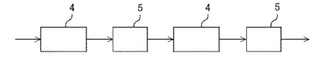
図6は、特開平10−235138号公報に開示された、従来の放電を用いたフッ素化合物ガスを含んだ排ガスの処理方法であり、4は放電分解装置、5は分解生成物除去装置を表わしている。かかる排ガスの処理方法は、上記のように構成され、放電分解装置4においてコロナ放電または無声放電によりCF4、C2F6、NF3又はSF6などの難分解性フッ素化合物を分解した後、分解生成物除去装置5を用いてこれら分解生成物を除去する工程を複数回繰り返す事により、放電による難分解性フッ素化合物の分解効率を低下させずに分解処理するものである。
【0006】
【発明が解決しようとする課題】
このような従来の排ガス処理方法においては、空気をキャリアガスとして用いており、この空気中に含まれる水素がフッ素化合物の分解促進剤として作用しているものと考えられるが、放電部と分解生成物除去装置を複数組み合わせ、放電により生成する分解生成物を除去した上で再度放電分解しないと、最終的に十分な分解効率が得られないという問題があった。また、この問題はフッ素化合物以外のハロゲン化合物においても同様の問題となっていた。
本発明者の知見によれば、かかる原因は、空気中に含まれる窒素のような2原子分子が振動準位を持ち、この振動準位の存在により放電のエネルギーが吸収され、ハロゲン化合物ガスの分解に有効に利用されないためであると考えられる。
【0007】
かかる状況下、本発明者らは、鋭意検討を行った結果、上記空気や窒素に変えてHe、Ne、Ar、Xe等の希ガスをキャリアガスとして用いると、フッ素化合物ガスを高効率で処理することができることを見出し、簡易かつランニングコストを抑制した高効率なハロゲン含有ガス処理方法及び装置を実現する本願発明に到達したものである。
【0008】
【課題を解決するための手段】
【0013】
この発明に係るハロゲン含有排ガス処理装置は、ハロゲン含有ガス排気設備に接続可能な排ガス導入部と、排ガス導入部に導入されたハロゲン含有排ガスを、ハロゲン化合物の分解処理を行う放電部へ供給するガス供給経路と、ガス供給経路に接続され、ガス供給経路に真空ポンプを保護するための希ガスを、ハロゲン含有排ガスを希釈するキャリアガスとして導入するキャリアガス供給手段並びに水素供与物質を導入する水素供給手段と、ガス供給経路に接続され、ガス供給経路に導入されたハロゲン含有排ガス中のハロゲン化水素を除去するハロゲン化水素前処理部とを備えたものである。
【0020】
【発明の実施の形態】
実施の形態1
本発明にかかるハロゲン含有排ガス処理装置の構成説明図の一例を図1に示す。かかるハロゲン含有排ガス処理装置は、ターボ分子ポンプ2とドライポンプ3と放電部4とハロゲン化水素除去手段5とポンプ保護ガスの発生源6と水素供給源9とガス排出口11にて構成されている。
【0021】
本発明にかかるハロゲン含有排ガス処理方法を図1に基づいて説明する。図1において、CVD装置1より排出されたフッ素化合物ガスはターボ分子ポンプ2にて排気されドライポンプ3を経由して放電部4へと導入される。また、CVD装置1から排出されるガス中にはフッ素化合物ガス以外にハロゲン化水素も存在するが、このハロゲン化水素は腐食性が強いため、CVD装置1から排出されるフッ素化合物ガスに対してポンプ保護ガスの発生源6からキャリアガスとして例えばHe、Ne、Ar、Xeなどの希ガスが供給される。これらキャリアガスはフッ素化合物ガスを希釈することにより、ハロゲン化水素等に起因するポンプ摺動部や配管内面の腐食を防止する効果を有する。また、CVD装置1から排出される固体有機物やSiO2等によるポンプのつまりを防止する効果も有する。本実施の形態においては、キャリアガスはCVD装置1への逆流防止を考慮してドライポンプ3に導入されているが、ポンプ保護の観点からは、キャリアガスのCVD装置1への逆流防止を考慮し適度なガス流量とすることで、これらキャリアガスをターボ分子ポンプに導入する事も可能である。次に、水素供給源9より水素もしくは水素化合物を含むガス、例えばH2Oガスが放電部4に供給される。すなわち、放電部4にはCVD装置1から排出されたフッ素化合物ガスとキャリアガスである希ガスとH2Oガスが導入されることになる。これらガスが導入されると、放電部4で放電によりフッ素化合物ガスが分解されると同時にH2Oガスと反応してハロゲン化水素を生成する。この時、例えば、フッ素化合物ガスがCF4の場合には次のような反応を生ずる。
CF4+2H2O→CO2+4HF
放電部4にて分解処理されたフッ素化合物ガスはキャリアガスやH2Oガスと一緒にハロゲン化水素除去手段5に導かれ、ハロゲン化水素(例えばHF)の除去後、一部のガスはガス排出口11より大気中に放出される。このハロゲン化水素除去手段5としては、水スクラバーや、バブリングタンクを通した後ドライヤで水分を除去するものや、ハロゲン化水素を除去するフィルター等が挙げられる。
【0022】
ハロゲン化水素除去後のガスには、キャリアガスである希ガスの他二酸化炭素等の不純物が含まれているが、ポンプの腐食対策やポンプが詰まらないために流すキャリアガスとして使用することには問題がないため、ハロゲン化水素除去手段5から大気中に放出されなかったガスはドライポンプ3に導入され、排気ガスのキャリアガスとして利用されることになる。このような構成にすることにより、ポンプの保護ガスの消費量が低減されるという効果がある。
【0023】
また、キャリアガスとして用いるHe、Ne、Ar、Xe等の希ガスは高価であるため、従来のように無毒化したガスとともに大気中に放出する装置においてはランニングコストが大幅に上昇するため、半導体製造装置の排ガスのキャリアガスとして実際の製造ラインに用いられることはなかった。しかしながら、これら希ガスを用いると、キャリアガスによる放電のエネルギー損失がなく、放電部と分解生成物の除去装置を複数組み合わせたような複雑な装置構成を用いる事なく、フッ素化合物ガスを高効率で処理することができるという効果があることが判明した。
【0024】
図4はキャリアガスとしてN2ガスを用いた場合とArガスを用いた場合において、放電部4における電力投入量を変化させ、フッ素化合物ガスの一種であるCF4の分解率の変化を調べたものである。縦軸にCF4の分解率(%)、横軸に投入電力量(W)を示している。図4よりArガスをキャリアガスとして用いた場合には500W以下の比較的少ない電力投入量においてもCF4が効率的に分解されることが分かる。なお、Arガスをキャリアガスに用いた場合の方がN2ガスをキャリアガスに用いた場合よりもCF4の分解効率が高い理由は、上述した振動準位の違いによるものと考えられている。
【0025】
また、本発明にかかるハロゲン含有排ガス処理装置においては、窒素ガスを使用しないため放電部4におけるフッ素化合物ガスの分解に伴う副生成物として毒性が高くかつ地球温暖化に対しても悪影響を及ぼす窒素酸化物が発生しないという利点も併せもつ。
【0026】
実施の形態2
本発明にかかるハロゲン含有排ガス処理装置の構成説明図の他の例を図2に示す。かかるハロゲン含有排ガス処理装置においては、CVD装置1から排気されたハロゲン化合物とキャリアガスを含む混合ガスを放電部4の前段で2つに分け一部のみを放電部4に導入し、残りはハロゲン化水素除去手段5にてハロゲン化水素を除去した後、ポンプもしくはガス配管等の保護ガスとして利用する。また、ターボ分子ポンプ2もしくはドライポンプ3の前段にハロゲン化水素除去手段5を設けておいてもよい。
【0027】
図2のような構成とし、放電部4に流入する処理ガス量を抑制することにより、放電部4における単位時間あたりのガス流量が減少するのでキャリアガスによる放電部における投入電力の吸収が抑制されるため、結果としてフッ素化合物ガスの処理効率が向上する効果が認められた。
【0028】
図5は放電部4において、ガス流量を変化させた場合のCF4の分解率を示したものである。横軸はガス流量(単位はSLM:standard liter per min.)、縦軸はCF4の分解率(%)を表している。キャリアガスとしてAr、N2を用いた場合を比較したが、処理ガスのガス流量が10SLM以下の場合はどちらのガスを用いても高いCF4の分解効率が得られていることが分かる。なお、Arガスを用いた場合にガス流量が大きくなってもCF4の分解効率が比較的高く保たれているのは、上述した振動準位の違いによるものと考えられている。
【0029】
実施の形態3
本発明にかかるハロゲン含有排ガス処理装置の構成説明図の他の例を図3に示す。かかるハロゲン含有排ガス処理装置においては、放電部4の前段にハロゲン化合物ガスとポンプの保護ガスとを分離するガス分離装置8を設置する。ガス分離装置8により分離されたハロゲン化合物ガスを放電部4に導入することにより、放電部5におけるハロゲン化合物ガスの濃度が高くなるとともに放電部4におけるガス量が減少するので処理効率が向上する。
【0030】
ガス分離装置8としては、分子の大きさの差を利用するフィルターや、質量の差を利用する遠心分離法、ノズル法、沸点の差を利用する蒸留等を利用した装置を用いることが可能である。
【0031】
【発明の効果】
【0033】
本発明にかかるハロゲン含有排ガス処理装置によれば、ハロゲン含有ガス排気設備に接続可能な排ガス導入部と、排ガス導入部に導入されたハロゲン含有排ガスを、ハロゲン化合物の分解処理を行う放電部へ供給するガス供給経路と、ガス供給経路に接続され、ガス供給経路に真空ポンプを保護するための希ガスを、ハロゲン含有排ガスを希釈するキャリアガスとして導入するキャリアガス供給手段並びに水素供与物質を導入する水素供給手段と、前記ガス供給経路に接続され、前記ガス供給経路に導入された前記ハロゲン含有排ガス中のハロゲン化水素を除去するハロゲン化水素前処理部とを備えており、特に、CVD装置やエッチング装置などの半導体製造装置から排出されるハロゲン化合物に対して、キャリアガスとしてHe、Ne、Ar、Xeなどの希ガスを用いて放電処理を行うことにより、効率的にハロゲン化合物を放電分解することができ、またハロゲン化水素が除去されたガスをキャリアガスとして利用することで、低ランニングコストでのシステムの運転が可能となるという効果がある。
【図面の簡単な説明】
【図1】 本発明にかかるハロゲン排含有ガス処理装置の構成の一例を示す図である。
【図2】 本発明にかかるハロゲン排含有ガス処理装置の構成の一例を示す図である。
【図3】 本発明にかかるハロゲン排含有ガス処理装置の構成の一例を示す図である。
【図4】 放電部における投入電力量を変化させた場合のCF4の分解率の変化を示す図である。
【図5】 処理ガスの流量を変化させた場合のCF4の分解率の変化を示す図である。
【図6】 従来のハロゲン含有排ガス処理装置の構成の一例を示す図である。
【符号の説明】
1 CVD装置、2 ターボ分子ポンプ、3 ドライポンプ、4 放電部、
5 ハロゲン化水素除去設備、6 ポンプ保護ガスの発生源、
8 ガス分離装置、9 水素供給源、11 ガス排出口。[0001]
BACKGROUND OF THE INVENTION
The present invention relates to a halogen-containing exhaust gas treatment method and apparatus, and more particularly to an exhaust gas treatment apparatus for decomposing a halogen compound contained in exhaust gas discharged from a semiconductor manufacturing apparatus or the like by discharge.
[0002]
[Prior art]
In semiconductor device manufacturing processes, fluorine compound gases such as CF 4 , C 2 F 6 , CHF 3 , SF 6 , and NF 3 are used for dry etching and CVD apparatus cleaning. These fluorine compound gases are introduced into a semiconductor manufacturing apparatus and discharged from a semiconductor manufacturing apparatus after being used for an etching process or the like. Usually, these fluorine compound gases are not completely decomposed in an etching process or the like, Part of the exhaust gas remains undecomposed.
[0003]
Since these fluorine compound gases have low activity in the air, they have been conventionally released into the air without any treatment except for NF 3 . However, in recent years, these fluorine compound gases have been considered to be related to the destruction of the ozone layer, and reduction of emissions of these gases has been demanded from the viewpoint of preventing global warming. Yes.
[0004]
Therefore, it is necessary to decompose or remove these fluorine compound gases by some method and change them to gases that reduce the environmental load. However, in the thermal decomposition method using combustion of hydrogen, natural gas, etc. There is a disadvantage that high concentration of NOx is generated. In addition, the removal method using adsorption has a problem of replacement of the adsorbent and a problem of regeneration, and a decomposition treatment method using electric discharge has been proposed as a non-thermal treatment method of the fluorine compound gas instead of these methods. ing.
[0005]
FIG. 6 shows a conventional method for treating exhaust gas containing a fluorine compound gas using discharge, disclosed in Japanese Patent Laid-Open No. 10-235138, wherein 4 is a discharge decomposition apparatus, and 5 is a decomposition product removal apparatus. ing. This exhaust gas treatment method is configured as described above, and after decomposing a hardly decomposable fluorine compound such as CF 4 , C 2 F 6 , NF 3 or SF 6 by corona discharge or silent discharge in the
[0006]
[Problems to be solved by the invention]
In such a conventional exhaust gas treatment method, air is used as a carrier gas, and hydrogen contained in this air is considered to act as a decomposition accelerator for fluorine compounds. If a plurality of object removal devices are combined and the decomposition products generated by the discharge are removed and then the discharge decomposition is not performed again, there is a problem that sufficient decomposition efficiency cannot be obtained finally. In addition, this problem is the same for halogen compounds other than fluorine compounds.
According to the knowledge of the present inventor, the cause is that a diatomic molecule such as nitrogen contained in the air has a vibration level, and the presence of this vibration level absorbs the energy of discharge, and the halogen compound gas This is considered to be because it is not used effectively for decomposition.
[0007]
Under such circumstances, as a result of intensive studies, the present inventors have processed fluorine compound gas with high efficiency when rare gases such as He, Ne, Ar, and Xe are used as a carrier gas instead of air or nitrogen. The present invention has been achieved to realize a highly efficient halogen-containing gas processing method and apparatus that is simple and suppresses running costs.
[0008]
[Means for Solving the Problems]
[0013]
The halogen-containing exhaust gas treatment apparatus according to the present invention includes an exhaust gas introduction unit connectable to a halogen-containing gas exhaust facility, and a gas that supplies the halogen-containing exhaust gas introduced into the exhaust gas introduction unit to a discharge unit that decomposes the halogen compound. A supply path, a carrier gas supply means connected to the gas supply path, for introducing a rare gas for protecting the vacuum pump into the gas supply path as a carrier gas for diluting the halogen-containing exhaust gas, and a hydrogen supply for introducing a hydrogen donating substance And a hydrogen halide pretreatment unit connected to the gas supply path and removing hydrogen halide in the halogen-containing exhaust gas introduced into the gas supply path.
[0020]
DETAILED DESCRIPTION OF THE INVENTION
Embodiment 1
An example of a configuration explanatory diagram of a halogen-containing exhaust gas treatment apparatus according to the present invention is shown in FIG. Such a halogen-containing exhaust gas treatment apparatus includes a turbo
[0021]
The halogen-containing exhaust gas treatment method according to the present invention will be described with reference to FIG. In FIG. 1, the fluorine compound gas discharged from the CVD apparatus 1 is exhausted by the turbo
CF 4 + 2H 2 O → CO 2 + 4HF
The fluorine compound gas decomposed in the
[0022]
The gas after removal of hydrogen halide contains impurities such as carbon dioxide in addition to the rare gas that is the carrier gas, but it should be used as a carrier gas to flow to prevent pump corrosion and clog the pump. Since there is no problem, the gas that has not been released into the atmosphere from the hydrogen
[0023]
In addition, since noble gases such as He, Ne, Ar, and Xe used as carrier gas are expensive, the running cost is greatly increased in a device that is released into the atmosphere together with a detoxified gas as in the prior art. It was not used in an actual production line as a carrier gas for exhaust gas from a production apparatus. However, when these rare gases are used, there is no energy loss of discharge due to the carrier gas, and the fluorine compound gas is highly efficient without using a complicated apparatus configuration in which a plurality of discharge units and decomposition product removal apparatuses are combined. It has been found that there is an effect that it can be processed.
[0024]
FIG. 4 shows changes in the decomposition rate of CF 4 , which is a kind of fluorine compound gas, by changing the power input amount in the
[0025]
Further, in the halogen-containing exhaust gas treatment apparatus according to the present invention, nitrogen gas is not used, so that nitrogen is highly toxic as a by-product accompanying the decomposition of the fluorine compound gas in the
[0026]
Another example of the configuration explanatory diagram of the halogen-containing exhaust gas treatment apparatus according to the present invention is shown in FIG. In such a halogen-containing exhaust gas treatment apparatus, the mixed gas containing the halogen compound and the carrier gas exhausted from the CVD apparatus 1 is divided into two parts at the front stage of the
[0027]
By adopting the configuration as shown in FIG. 2 and suppressing the amount of processing gas flowing into the
[0028]
FIG. 5 shows the decomposition rate of CF 4 in the
[0029]
FIG. 3 shows another example of the configuration explanatory diagram of the halogen-containing exhaust gas treatment apparatus according to the present invention. In such a halogen-containing exhaust gas treatment device, a
[0030]
As the
[0031]
【The invention's effect】
[0033]
According to the halogen-containing exhaust gas treatment apparatus according to the present invention, the exhaust gas introduction part connectable to the halogen-containing gas exhaust equipment and the halogen-containing exhaust gas introduced into the exhaust gas introduction part are supplied to the discharge part that decomposes the halogen compound. A gas supply path, a carrier gas supply means connected to the gas supply path, for introducing a rare gas for protecting the vacuum pump as a carrier gas for diluting the halogen-containing exhaust gas, and a hydrogen donor substance are introduced into the gas supply path A hydrogen supply means, and a hydrogen halide pretreatment unit that is connected to the gas supply path and removes hydrogen halide in the halogen-containing exhaust gas introduced into the gas supply path. For halogen compounds discharged from semiconductor manufacturing equipment such as etching equipment, carrier gases such as He, Ne, By performing the discharge treatment using a rare gas such as r or Xe, the halogen compound can be efficiently decomposed by discharge, and the gas from which the hydrogen halide has been removed is used as a carrier gas, resulting in low running. The system can be operated at a low cost.
[Brief description of the drawings]
FIG. 1 is a diagram showing an example of the configuration of a halogen exhaust gas processing apparatus according to the present invention.
FIG. 2 is a diagram showing an example of the configuration of a halogen exhaust gas processing apparatus according to the present invention.
FIG. 3 is a diagram showing an example of the configuration of a halogen exhaust gas processing apparatus according to the present invention.
FIG. 4 is a diagram showing a change in the decomposition rate of CF 4 when the input power amount in the discharge unit is changed.
FIG. 5 is a diagram showing a change in the decomposition rate of CF 4 when the flow rate of the processing gas is changed.
FIG. 6 is a diagram showing an example of the configuration of a conventional halogen-containing exhaust gas treatment apparatus.
[Explanation of symbols]
1 CVD equipment, 2 turbo molecular pump, 3 dry pump, 4 discharge section,
5 Hydrogen halide removal equipment, 6 Sources of pump protective gas,
8 Gas separator, 9 Hydrogen supply source, 11 Gas outlet.
Claims (4)
Priority Applications (1)
| Application Number | Priority Date | Filing Date | Title |
|---|---|---|---|
| JP2001092109A JP4558233B2 (en) | 2001-03-28 | 2001-03-28 | Halogen-containing exhaust gas treatment equipment |
Applications Claiming Priority (1)
| Application Number | Priority Date | Filing Date | Title |
|---|---|---|---|
| JP2001092109A JP4558233B2 (en) | 2001-03-28 | 2001-03-28 | Halogen-containing exhaust gas treatment equipment |
Publications (3)
| Publication Number | Publication Date |
|---|---|
| JP2002282651A JP2002282651A (en) | 2002-10-02 |
| JP2002282651A5 JP2002282651A5 (en) | 2007-01-11 |
| JP4558233B2 true JP4558233B2 (en) | 2010-10-06 |
Family
ID=18946626
Family Applications (1)
| Application Number | Title | Priority Date | Filing Date |
|---|---|---|---|
| JP2001092109A Expired - Fee Related JP4558233B2 (en) | 2001-03-28 | 2001-03-28 | Halogen-containing exhaust gas treatment equipment |
Country Status (1)
| Country | Link |
|---|---|
| JP (1) | JP4558233B2 (en) |
Families Citing this family (1)
| Publication number | Priority date | Publication date | Assignee | Title |
|---|---|---|---|---|
| KR102457227B1 (en) * | 2022-08-26 | 2022-10-20 | 주식회사 에코에이블 | Device for treating pollutant emitted from semiconductor production facility |
Citations (3)
| Publication number | Priority date | Publication date | Assignee | Title |
|---|---|---|---|---|
| JPH07299321A (en) * | 1994-05-09 | 1995-11-14 | Niigata Eng Co Ltd | Gas recovering and circulating apparatus |
| JPH11156156A (en) * | 1997-11-27 | 1999-06-15 | Seiko Epson Corp | Method and apparatus for treatment of halogen-based gas, reaction treater and semi-conductor device |
| JP2000009037A (en) * | 1998-06-18 | 2000-01-11 | Fujitsu Ltd | Exhaust device and exhaust method |
-
2001
- 2001-03-28 JP JP2001092109A patent/JP4558233B2/en not_active Expired - Fee Related
Patent Citations (3)
| Publication number | Priority date | Publication date | Assignee | Title |
|---|---|---|---|---|
| JPH07299321A (en) * | 1994-05-09 | 1995-11-14 | Niigata Eng Co Ltd | Gas recovering and circulating apparatus |
| JPH11156156A (en) * | 1997-11-27 | 1999-06-15 | Seiko Epson Corp | Method and apparatus for treatment of halogen-based gas, reaction treater and semi-conductor device |
| JP2000009037A (en) * | 1998-06-18 | 2000-01-11 | Fujitsu Ltd | Exhaust device and exhaust method |
Also Published As
| Publication number | Publication date |
|---|---|
| JP2002282651A (en) | 2002-10-02 |
Similar Documents
| Publication | Publication Date | Title |
|---|---|---|
| US6949225B1 (en) | Method and apparatus for treating a waste gas containing fluorine-containing compounds | |
| KR100309963B1 (en) | Exhaust System and Exhaust Method | |
| US7972582B2 (en) | Method and apparatus for treating exhaust gas | |
| US20060099123A1 (en) | Utilisation of waste gas streams | |
| JP2001185539A (en) | System and method for collecting gas | |
| KR102089599B1 (en) | Waste gas treatment device for semiconductor | |
| TWI400354B (en) | Method of treating a gas stream | |
| JPH11218318A (en) | Exhaust gas treating facility | |
| KR101957440B1 (en) | Piping apparatus with harmful gas treatment appratus using plasma reaction and facility for treating harmful gas having the same | |
| KR101960536B1 (en) | Semiconductor dry scrubber system | |
| JP4558233B2 (en) | Halogen-containing exhaust gas treatment equipment | |
| JP7284530B2 (en) | Hydrogen recovery regeneration system | |
| JP2008168169A (en) | Method for recovering neon | |
| TW571366B (en) | Cleaning gas for semiconductor production equipment and cleaning method using the gas | |
| JP4549563B2 (en) | Halogen-containing gas treatment equipment | |
| JPWO2018221021A1 (en) | Exhaust gas pressure reduction method and apparatus | |
| KR200267601Y1 (en) | Waste-gas cleaning device with Plazma | |
| JP2003245520A (en) | Pfc decomposition method, pfc decomposition apparatus and method for manufacturing semiconductor device | |
| KR20140139888A (en) | Sulphur hexafluoride treatment system | |
| JP2007216229A (en) | Apparatus for treating exhaust gas including fluorine-containing compound | |
| JP5986852B2 (en) | Electrothermal gas abatement system | |
| JP2001246221A (en) | Exhaust gas treatment apparatus | |
| JPH1147550A (en) | Exhaust gas treatment method | |
| JP2002324785A (en) | Method for recycling perfluorocompound | |
| JPH07328663A (en) | Device for treating ammoniacal nitrogen-containing waste water |
Legal Events
| Date | Code | Title | Description |
|---|---|---|---|
| RD01 | Notification of change of attorney |
Free format text: JAPANESE INTERMEDIATE CODE: A7421 Effective date: 20040708 |
|
| A521 | Written amendment |
Free format text: JAPANESE INTERMEDIATE CODE: A523 Effective date: 20061121 |
|
| A621 | Written request for application examination |
Free format text: JAPANESE INTERMEDIATE CODE: A621 Effective date: 20061121 |
|
| A977 | Report on retrieval |
Free format text: JAPANESE INTERMEDIATE CODE: A971007 Effective date: 20090907 |
|
| A131 | Notification of reasons for refusal |
Free format text: JAPANESE INTERMEDIATE CODE: A131 Effective date: 20091013 |
|
| RD01 | Notification of change of attorney |
Free format text: JAPANESE INTERMEDIATE CODE: A7421 Effective date: 20091118 |
|
| A521 | Written amendment |
Free format text: JAPANESE INTERMEDIATE CODE: A523 Effective date: 20091208 |
|
| A131 | Notification of reasons for refusal |
Free format text: JAPANESE INTERMEDIATE CODE: A131 Effective date: 20100323 |
|
| A521 | Written amendment |
Free format text: JAPANESE INTERMEDIATE CODE: A523 Effective date: 20100514 |
|
| TRDD | Decision of grant or rejection written | ||
| A01 | Written decision to grant a patent or to grant a registration (utility model) |
Free format text: JAPANESE INTERMEDIATE CODE: A01 Effective date: 20100713 |
|
| A01 | Written decision to grant a patent or to grant a registration (utility model) |
Free format text: JAPANESE INTERMEDIATE CODE: A01 |
|
| A61 | First payment of annual fees (during grant procedure) |
Free format text: JAPANESE INTERMEDIATE CODE: A61 Effective date: 20100721 |
|
| FPAY | Renewal fee payment (event date is renewal date of database) |
Free format text: PAYMENT UNTIL: 20130730 Year of fee payment: 3 |
|
| LAPS | Cancellation because of no payment of annual fees |