JP4558219B2 - Magnetic resonance imaging system - Google Patents
Magnetic resonance imaging system Download PDFInfo
- Publication number
- JP4558219B2 JP4558219B2 JP2001013321A JP2001013321A JP4558219B2 JP 4558219 B2 JP4558219 B2 JP 4558219B2 JP 2001013321 A JP2001013321 A JP 2001013321A JP 2001013321 A JP2001013321 A JP 2001013321A JP 4558219 B2 JP4558219 B2 JP 4558219B2
- Authority
- JP
- Japan
- Prior art keywords
- diffusion
- magnetic resonance
- resonance imaging
- imaging apparatus
- arrow
- Prior art date
- Legal status (The legal status is an assumption and is not a legal conclusion. Google has not performed a legal analysis and makes no representation as to the accuracy of the status listed.)
- Expired - Fee Related
Links
Images


Landscapes
- Magnetic Resonance Imaging Apparatus (AREA)
Description
【0001】
【発明の属する技術分野】
本発明は、磁気共鳴イメージング装置(以下、MRI装置と称する。)に係り、具体的には、拡散強調画像を取得する機能を備えたMRI装置に関する。
【0002】
【従来の技術】
MRI装置は、磁気共鳴現象を利用して生体などの被検体の対象部位の断層像を得る装置である。拡散強調画像は、対象部位における分子拡散の程度を示す画像であり、例えば、生体内の水の拡散の程度が低い部位を観察して、脳梗塞などの病変部位の診断等に用いられる。この拡散強調画像は、断層像の撮像時に特別な傾斜磁場(MPG:Motion Probing Gradient)を印加することにより取得する。そして、MPGを印加する物理的な軸及びMPG強度等のMPG条件を変化させることにより、拡散方向及び拡散強度を任意に設定することができる。そこで、所望の拡散強調画像を取得するために、撮像に先だってMRI装置に拡散方向及び拡散強度を設定するためのMPG条件を設定する必要がある。
【0003】
従来、MPG条件を設定する方法としては、
(1)操作卓に予め登録あるいは用意されている拡散方向及び拡散強度の選択肢の中から必要なものを選択すると、操作卓がMPG情報を計算してMRI装置に設定する方法、
(2)入力装置から操作者がMPG条件をMRI装置に入力することにより、拡散方向及び拡散強度を任意に設定する方法がある。
【0004】
【発明が解決しようとする課題】
しかしながら、拡散方向及び拡散強度を設定するにあたって、従来の設定方法(1)によれば、予め登録されているパラメータに制限されるため、操作者が自由にMPG情報を設定することができないという問題がある。一方、従来の設定方法(2)によると、操作者が任意に拡散方向及び拡散強度を設定することができるが、設定作業は手間のかかるものであることから、MR撮像による検査効率が低下するという問題がある。
【0005】
本発明は、拡散強調画像の拡散条件を任意にかつ容易に設定できるようにすることを課題とする。
【0006】
【課題を解決するための手段】
上記課題を解決するため、本発明の磁気共鳴イメージング装置は、静磁場発生手段と、傾斜磁場発生手段と、高周波磁場パルス照射手段と、被検体から発生する磁気共鳴信号を受信する受信手段と、前記磁気共鳴信号に基づいて画像を再構成する信号処理手段と、画像表示手段と、前記各手段を制御する制御手段と、入力手段とを備えた磁気共鳴イメージング装置において、前記画像表示手段は、拡散強調画像における拡散方向と拡散強度を示す情報を表示することを特徴とする。
【0007】
より詳しくは、制御手段は、入力手段から拡散強調画像撮像の選択信号が入力されたとき画像表示手段に拡散方向と拡散強度を示す図形を表示させ、入力手段の指令に応じて図形の形状を変形させ、この図形の形状に基づいて拡散方向及び拡散強度を設定するものである。
【0008】
また、この図形は矢印で表され、矢印の方向は拡散方向、矢印の長さは拡散強度を示すようにしてもよい。さらに、矢印に色を付け色調により拡散強度を示してよいし、矢印を3次元表示させてもよい。
【0009】
このように構成することにより、画面に表示された図形の形状、例えば矢印の向きと長さを、ポインティングデバイスなどの入力手段により操作者が操作することにより、拡散条件を簡単に設定することができることから、操作者は所望の拡散条件を任意にかつ容易に設定することができる。
【0010】
【実施の形態】
以下、本発明の実施の形態を図面に基づいて用いて説明する。図1は一実施形態の拡散条件設定手順の一例を示すフローチャート、図2は一実施形態のMRI装置の全体構成を示すブロック図、図3は拡散強調画像の一実施形態の撮像シーケンスを示している。
【0011】
図2に示すように、MRI装置は、静磁場発生磁気回路1、傾斜磁場発生系2、送信系3、受信系4、信号処理系5、シーケンサ6、中央処理装置(CPU)7、操作部8等を備えて構成される。静磁場発生磁気回路1は、被検体9が置かれる空間に均一な静磁場を発生させるものである。その静磁場の方向は、通常、被検体9の体軸方向又は体軸に直交する方向である。また、静磁場発生磁気回路1は、永久磁石方式、常電導電磁石方式又は超電導電磁石方式の磁場発生手段により形成されている。傾斜磁場発生系2は、直交3軸(X、Y、Z)方向の傾斜磁場を発生する傾斜磁場コイル10と、その傾斜磁場コイル10の駆動電流を供給する傾斜磁場電源11を有して構成されている。傾斜磁場電源11は、シーケンサ6の命令に従って直交3軸(X,Y,Z)方向の傾斜磁場Gs、Gp、Gfを被検体9に印加するようになっている。この傾斜磁場の与え方によって断層像のスライス面を設定することができるとともに、計測されるエコー信号に位置情報をエンコードすることができる。シーケンサ6はCPU7の制御により動作し、パルスシーケンスと称される撮像シーケンスに従って、傾斜磁場発生系2、送信系3、受信系4等に命令を送り、断層像を撮像するのに必要な制御を実行するものである。
【0012】
送信系3は、被検体9の生体組織を構成する原子核に核磁気共鳴を起こさせるための高周波磁場パルスを照射するもので、高周波発振器12、変調器13、高周波増幅器14及び高周波照射コイル15を有して構成されている。そして、送信系3は、シーケンサ6の命令に従って、高周波発振器12から出力される高周波パルスを変調器13で振幅変調し、さらに高周波増幅器14で増幅した後、高周波照射コイル15に供給して高周波パルス(RFパルス)を被検体9に照射するようになっている。
【0013】
受信系4は、被検体9の生体組織の原子核の核磁気共鳴により放出されるエコー信号(NMR信号)を検出するもので、受信側の高周波受信コイル16、増幅器17、直交位相検波器18及びA/D変換器19を有して構成される。高周波受信コイル16により受波されたNMR信号は増幅器17で増幅され、直交位相検波器18で検波された後、A/D変換器19でディジタル信号の計測データに変換される。なお、シーケンサ6の制御によるタイミングで直交位相検波器18により位相を90°ずらしてサンプリングされた二系列の計測データは、信号処理系5に送られる。
【0014】
信号処理系5は、CPU7、ROM20、RAM21、光磁気ディスク22、CRTなどのディスプレイ23及び磁気ディスク24を有して構成される。CPU7は、入力されるエコー信号についてフーリエ変換、補正係数計算、画像再構成処理等の処理、及びシーケンサ6の制御を行ない、任意断面の信号強度分布あるいは所定の処理をした画像を作成して、ディスプレイ23に断層像として表示するようになっている。ROM20は、経時的な画像解析処理及び計測を行なうプログラムや、その実行に用いる不変のパラメータなどを記憶する。RAM21は、前計測で用いた計測パラメータや、送信系4で検出したエコー信号、及び関心領域設定に用いる画像を一時保管すると共に、その関心領域を設定するためのパラメータなどを記憶する。光磁気ディスク22及び磁気ディスク24は、CPU7により再構成された画像データを記録する。ディスプレイ23は、光磁気ディスク22及び磁気ディスク24に格納されている画像データを映像化して断層像として表示する。操作部8は、信号処理系5で実行する処理の制御情報を入力する入力手段であり、例えば、トラックボール又はマウス25やキーボード26を備えて構成される。
【0015】
特に、本発明の特徴に係る拡散強調画像を撮像するため、シーケンサ6は拡散強調画像を撮像するパルスシーケンスを実行する機能を備えるとともに、CPU7は操作部8から入力される拡散強調画像の撮像指令、拡散条件等の入力指令に基づいて、ディスプレイ23及びシーケンサ6を制御するようになっている。
【0016】
ここで、拡散強調画像の撮像シーケンスの一実施形態を、図3に基づいて説明する。同図は、上から順に、高周波磁場パルス(RF)、スライス傾斜磁場パルス(Gs)、位相エンコード傾斜磁場パルス(Gp)、リードアウト傾斜磁場パルス又は周波数エンコード傾斜磁場パルス(Gf)、エコー信号(Signal)を示し、横軸はそれらの印加タイミング又は計測タイミング、縦軸はそれらの強度を示している。
【0017】
図3の撮像シーケンスはスピンエコー−エコプレーナイメージング(SE−EPI)法であり、スライス断面を選択するスライス傾斜磁場パルス(Gs)33と共にRF90度パルス31を印加して、被検体の所望のスライス部位を励起する。次いで、拡散強調画像を得るために用いる前側MPGパルス34を印加する。本例の場合は、3つの全ての軸方向にMPGパルスを印加しているが、所望の拡散画像に応じてMPGパルスを印加する軸は適宜選択される。次に、スピンエコーを発生させるため、RF180度パルス32をスライス傾斜磁場パルス35と共に印加した後、後側MPGパルス36を印加するした後、エコー信号を取得するシーケンスを実行する。
【0018】
まず、エコー信号に位相情報を付与するために位相エンコード傾斜磁場パルス41を印加した後、リードアウト傾斜磁場パルス39を繰り返し印加してエコー信号を計測する。本実施形態の場合は、4つのエコー信号42−1,…、42−4からなるエコートレインを取得する例を示している。なお、エコー信号42−1はRF90度パルスを印加してから所定のエコータイムTE後に計測する。位相エンコード傾斜磁場パルス43は、エコー信号42−1,…、42−4にそれぞれ個別の位相情報を付与するために印加するものである。このように、1回の励起で、4つのエコー信号を計測することにより、通常のスピンエコー法(SE法)の4倍の速さで計測を行う。このようなシーケンスを、位相エンコ−ド傾斜磁場パルス41の強度を変化させて、1枚の画像を構成するのに必要な磁気共鳴信号を得るまで繰り返し実行する。シーケンスを実行して得られるエコー信号は、受信系4により処理された後、CPU7において所定の画像再構成処理を行なって所望の拡散強調画像を再構成し、ディスプレイ23に表示する。
【0019】
このような拡散強調画像の撮像シーケンスは、例えば1つのスライスについて、拡散強度を表わす傾斜磁場因子であるb値を0として、拡散強調しない1枚の画像を撮像するとともに、b値を所望の値に設定して複数の拡散方向(例えば、6方向)について複数枚の画像を撮像する。ここで、b値は、図3に示したMPGパルス34,36の強度に相関する値であり、拡散の程度を調整する値である。また、拡散方向は、MPGパルス34,36の印加軸の方向(含む、合成方向)であり、例えば、狭窄している部位などを観察するためには、様々な方向の拡散強調画像が有用である。したがって、これらの拡散条件を、1つのスライス断面毎に、所望の拡散強調画像に応じて設定する必要がある。
【0020】
ここで、本発明の特徴に係る拡散条件の設定について、図1に示したフローチャート及び図4〜図9に基づいて説明する。同フローチャートはCPU7における処理を中心に表わしたものである。
【0021】
(ステップS1)
操作部8のトラックボール又はマウス25等のポインティングデバイス、あるいはキーボード26等の入力手段により拡散強調画像撮像モードの選択信号が入力されると、拡散条件の設定処理を開始する。
【0022】
(ステップS2)
拡散条件の設定処理は、ディスプレイ23に操作画面を表示するとともに、その操作画面上に拡散方向および強度設定用の図形を表示することにより開始する。操作画面は、例えば図4に示すように、被検体の撮像対象部位の図形51と、スライス部位の設定図形52と、拡散条件の設定図形53を含んで構成される。この操作画面は、通常の断層像を表示する画面と共にディスプレイ23に表示してもよい。拡散条件の設定図形53は、撮影断面であるスライス面に平行な座標面54と矢印55を有してなる。座標面54はスライス面の腹部側(A)と背中側(P)を結ぶ縦軸(AP軸)と、スライス面の左右を結ぶ横軸軸(RL軸)からなる。矢印55は座標面54の中心に表示される。
【0023】
(ステップS3)
拡散強調画像の各種条件は、操作画面の図形等をポインティングデバイスによって操作することにより設定できるようになっている。つまり、スライスの位置及び傾きなどは、従来から行なわれているように、設定図形52をポインティングデバイスで操作して設定する。また、拡散方向及び拡散強度は、図5に示すように、矢印55の向き及び長さに対応付けられており、トラックボールやマウスなどのポインティングデバイスを操作することによって、任意に設定可能に形成されている。例えば、マウスの左ボタンで矢印55の一端をクリックして一方向にドラッグすることによって、CPU7は矢印55の長さを変更するようになっている。また、同様にクリックして現在の方向とは異なる方向にドラッグすることによって、CPU7は矢印55の向きを変更するようになっている。
【0024】
(ステップS4)
このようにして画面上で設定された矢印55の向きと長さは、CPU7により読取られ拡散方向及び拡散強度の設定条件が計算される。なお、複数の拡散方向は一般に相対的に一定の関係にあることから、設定された1つの拡散方向に基づいて他の拡散方向は計算で求めるようにしている。
【0025】
(ステップS5)
設定された拡散強度に基づいてCPU7により計算されたb値(b−value)と、矢印55により設定された拡散方向(angle)が設定図形53に重ねて表示されるとともに、シーケンサ6にその拡散条件が設定される。すなわち、矢印55により設定された拡散方向及び拡散強度にに基づいて、直交3軸(X、Y、Z)にそれぞれ印加する傾斜磁場強度が求められ、これに従って拡散強調画像の撮像シーケンスが設定される。なお、傾斜磁場強度は、傾斜磁場発生電源など装置の能力により限界があることから、設定された矢印55の向き及び長さから求まる各軸の傾斜磁場強度をその限界値と比較し、限界を超える場合は矢印55の向きと長さに制限を設ける。これにより、傾斜磁場発生電源などの装置を保護できる。
【0026】
上述したように、本実施形態によれば、操作画面に表示された矢印55を、操作者がポインティングデバイスで操作することにより、拡散条件を簡単に設定することができることから、操作者は所望の拡散条件を任意にかつ容易に設定することができる。
【0027】
上記実施形態においては、矢印55の向きと長さを画面上で操作して、拡散方向と拡散強度を可変設定するようにしたが、矢印に限らず、要は設定画像の形態を画面上で可変することにより拡散方向と拡散強度を可変設定するものであれば、設定画像の形態はどのようなものでもよい。
【0028】
また、上記実施形態の操作画面は、1枚の矢状断面画像に対して横断面の拡散協調画像を撮像する場合を示したが、これに代えて図6に示すように、矢状断面画像と冠状断面画像の2枚の操作画面を一対として表示するようにしてもよい。
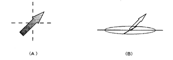
すなわち、図6(A)は図5と同じく矢状断面画像であるが、図6(B)は冠状断面画像であり、拡散条件の設定図形56は線57によって示した励起断面(スライス面)を横から見た状態で表示している。これにより、スライス面に対する拡散方向の傾斜を容易に認識できるとともに、所望の場合はポインティングデバイスを操作することにより、拡散方向をスライス面に対して非平行に直感的に設定できる。例えば、中央ボタンで矢印をクリックしながら操作する。この場合、矢印55のスライス面からの傾きに応じて、図7(A)に示すように、矢印55の色付けを段階的に変化させたり、図7(B)に示すように、3次元表示することにより、操作者にスライス面に対する拡散方向の傾きを容易に認識させることができる。
【0029】
また、図5及び図6の例は、被検体の撮像対象部位の図形51を表示するようにしたが、これに代えて、図8に示すように、撮影対象部位についてMPGを印加しないで取得した断層像58などの比較画像を操作画面に表示するようにしてもよい。
【0030】
更に、上述のようにして矢印55を操作して設定した拡散方向及び拡散強度に基づき、CPU7により計算した詳細な条件を図9に示す設定画面に出力表示する。これにより、操作者は設定した拡散条件に対応する各軸(X,Y,Z)の傾斜磁場強度mT/m、b-value、MPGパターン(MPG Pattern)などの詳細な条件を確認することができる。この場合、例えば、右ボタンで矢印をクリックすることにより、図9の設定画面を表示するようにすることができる。また、図9の設定画面を用いて、各軸(X,Y,Z)の傾斜磁場強度mT/m、b-value、MPGパターン(MPG Pattern)などの詳細な条件を操作者がキーボードなどを操作して入力するようにしてもよい。例えば、MPGの印加パターンが複数存在する場合は、この画面で印加パターンを選択することが可能である。
【0031】
また、撮影断面が複数ある場合は、拡散方向と拡散強度を断面ごとに変えて設定することも可能であり、撮影前に設定した矢印の方向および長さは、予め指示しておくことにより、再構成された画像に添付するようにすることも可能である。
【0032】
【発明の効果】
以上述べたように、本発明によれば、拡散強調画像の拡散条件を任意にかつ容易に設定できる。
【図面の簡単な説明】
【図1】本発明の特徴に係る拡散条件設定手順の一実施の形態を示すフローチャートである。
【図2】本発明の磁気共鳴イメージング装置の一実施の形態の全体構成図である。
【図3】拡散強調画像の撮像シーケンスの一例を示す図である。
【図4】拡散条件の設定画面の一例を示す図である。
【図5】図4の矢印の形態が有する特徴を説明する図である。
【図6】拡散条件の設定画面の他の例を示す図である。
【図7】図6の矢印の表示の変形例を示す図である。
【図8】拡散条件の設定画面の更に他の例を示す図である。
【図9】拡散条件の詳細な設定画面の1例を示す図である。
【符号の説明】
1 静磁場発生回路
2 傾斜磁場発生系
3 送信系
4 受信系
5 信号処理系
6 シーケンサ
7 CPU
8 操作部
10 傾斜磁場コイル
15 高周波照射コイル
16 高周波受信コイル[0001]
BACKGROUND OF THE INVENTION
The present invention relates to a magnetic resonance imaging apparatus (hereinafter referred to as an MRI apparatus), and more specifically, to an MRI apparatus having a function of acquiring a diffusion weighted image.
[0002]
[Prior art]
An MRI apparatus is an apparatus that obtains a tomographic image of a target region of a subject such as a living body using a magnetic resonance phenomenon. The diffusion weighted image is an image showing the degree of molecular diffusion in the target region, and is used for, for example, diagnosing a lesion site such as cerebral infarction by observing a site where the degree of water diffusion in the living body is low. This diffusion weighted image is acquired by applying a special gradient magnetic field (MPG: Motion Probing Gradient) when capturing a tomographic image. The diffusion direction and diffusion intensity can be arbitrarily set by changing the MPG conditions such as the physical axis to which MPG is applied and the MPG intensity. Therefore, in order to acquire a desired diffusion weighted image, it is necessary to set MPG conditions for setting the diffusion direction and the diffusion intensity in the MRI apparatus prior to imaging.
[0003]
Conventionally, as a method of setting the MPG condition,
(1) A method in which the console calculates MPG information and sets it in the MRI apparatus when a necessary one is selected from the diffusion direction and diffusion intensity options registered or prepared in advance on the console.
(2) There is a method of arbitrarily setting the diffusion direction and the diffusion intensity by inputting the MPG condition from the input device to the MRI apparatus.
[0004]
[Problems to be solved by the invention]
However, when setting the diffusion direction and the diffusion intensity, the conventional setting method (1) is limited to parameters registered in advance, so that the operator cannot freely set the MPG information. There is. On the other hand, according to the conventional setting method (2), the operator can arbitrarily set the diffusion direction and the diffusion intensity. However, since the setting work is time-consuming, the inspection efficiency by MR imaging decreases. There is a problem.
[0005]
An object of the present invention is to make it possible to arbitrarily and easily set a diffusion condition of a diffusion weighted image.
[0006]
[Means for Solving the Problems]
In order to solve the above problems, a magnetic resonance imaging apparatus of the present invention includes a static magnetic field generating means, a gradient magnetic field generating means, a high frequency magnetic field pulse irradiating means, a receiving means for receiving a magnetic resonance signal generated from a subject, In a magnetic resonance imaging apparatus comprising signal processing means for reconstructing an image based on the magnetic resonance signal, image display means, control means for controlling each means, and input means, the image display means comprises: the information indicating the spreading direction and spreading intensity in the diffusion weighted image, characterized in that the table Shimesuru.
[0007]
More specifically, the control means displays a figure indicating the diffusion direction and the diffusion intensity on the image display means when a selection signal for diffusion weighted imaging is input from the input means, and changes the shape of the figure in accordance with an instruction from the input means. The deformation direction and the diffusion intensity are set based on the shape of the figure.
[0008]
Moreover, this figure may be represented by an arrow, the direction of the arrow may indicate the diffusion direction, and the length of the arrow may indicate the diffusion intensity. Further, the arrow may be colored to indicate the diffusion intensity by the color tone, or the arrow may be displayed three-dimensionally.
[0009]
By configuring in this way, it is possible to easily set the diffusion condition by the operator operating the shape of the graphic displayed on the screen, for example, the direction and length of the arrow with an input means such as a pointing device. Therefore, the operator can arbitrarily and easily set desired diffusion conditions.
[0010]
Embodiment
Hereinafter, embodiments of the present invention will be described with reference to the drawings. FIG. 1 is a flowchart illustrating an example of a diffusion condition setting procedure according to an embodiment, FIG. 2 is a block diagram illustrating an overall configuration of the MRI apparatus according to the embodiment, and FIG. 3 illustrates an imaging sequence according to an embodiment of the diffusion weighted image. Yes.
[0011]
As shown in FIG. 2, the MRI apparatus includes a static magnetic field generation magnetic circuit 1, a gradient magnetic field generation system 2, a transmission system 3, a reception system 4, a signal processing system 5, a
[0012]
The transmission system 3 irradiates a high-frequency magnetic field pulse for causing nuclear magnetic resonance to nuclei constituting the living tissue of the
[0013]
The receiving system 4 detects an echo signal (NMR signal) emitted by nuclear magnetic resonance of the nucleus of the living tissue of the
[0014]
The signal processing system 5 includes a CPU 7, a
[0015]
In particular, the
[0016]
Here, an embodiment of a diffusion-weighted image capturing sequence will be described with reference to FIG. The figure shows, in order from the top, a high-frequency magnetic field pulse (RF), a slice gradient magnetic field pulse (Gs), a phase encoding gradient magnetic field pulse (Gp), a readout gradient magnetic field pulse or a frequency encoding gradient magnetic field pulse (Gf), and an echo signal ( Signal), the horizontal axis represents their application timing or measurement timing, and the vertical axis represents their intensity.
[0017]
The imaging sequence in FIG. 3 is a spin echo-ecoplanar imaging (SE-EPI) method, in which an RF 90
[0018]
First, a phase encoding gradient
[0019]
In such a sequence for capturing a diffusion weighted image, for example, for one slice, the b value that is a gradient magnetic field factor indicating the diffusion strength is set to 0, and one image that is not diffusion weighted is captured, and the b value is set to a desired value. And a plurality of images are captured in a plurality of diffusion directions (for example, six directions). Here, the b value is a value that correlates with the intensity of the
[0020]
Here, the setting of the diffusion condition according to the feature of the present invention will be described based on the flowchart shown in FIG. 1 and FIGS. This flowchart mainly shows processing in the CPU 7.
[0021]
(Step S1)
When a selection signal for the diffusion weighted image capturing mode is input by a trackball of the operation unit 8 or a pointing device such as the mouse 25 or an input means such as the
[0022]
(Step S2)
The diffusion condition setting process starts by displaying an operation screen on the
[0023]
(Step S3)
Various conditions of the diffusion weighted image can be set by operating a figure on the operation screen with a pointing device. That is, the position and inclination of the slice are set by operating the setting figure 52 with a pointing device, as is conventionally done. Further, as shown in FIG. 5, the diffusion direction and the diffusion intensity are associated with the direction and length of the
[0024]
(Step S4)
The direction and length of the
[0025]
(Step S5)
The b value (b-value) calculated by the CPU 7 based on the set diffusion intensity and the diffusion direction (angle) set by the
[0026]
As described above, according to the present embodiment, the operator can easily set the diffusion condition by operating the
[0027]
In the above embodiment, the direction and length of the
[0028]
Moreover, although the operation screen of the said embodiment showed the case where the spreading | diffusion cooperation image of a cross section was imaged with respect to one sagittal cross-section image, instead of this, as shown in FIG. And the two operation screens of the coronal slice image may be displayed as a pair.
That is, FIG. 6A is a sagittal cross-sectional image as in FIG. 5, but FIG. 6B is a coronal cross-sectional image, and the diffusion condition setting figure 56 is an excitation cross-section (slice plane) indicated by a
[0029]
In the example of FIGS. 5 and 6, the figure 51 of the imaging target part of the subject is displayed. Instead, as shown in FIG. 8, the imaging target part is acquired without applying MPG. A comparative image such as the
[0030]
Further, the detailed conditions calculated by the CPU 7 are output and displayed on the setting screen shown in FIG. 9 based on the diffusion direction and the diffusion intensity set by operating the
[0031]
In addition, when there are a plurality of imaging sections, it is also possible to set the diffusion direction and diffusion intensity for each section, and the direction and length of the arrows set before imaging are designated in advance, It is also possible to attach it to the reconstructed image.
[0032]
【The invention's effect】
As described above, according to the present invention, the diffusion condition of the diffusion weighted image can be set arbitrarily and easily.
[Brief description of the drawings]
FIG. 1 is a flowchart showing an embodiment of a diffusion condition setting procedure according to a feature of the present invention.
FIG. 2 is an overall configuration diagram of an embodiment of a magnetic resonance imaging apparatus of the present invention.
FIG. 3 is a diagram illustrating an example of an imaging sequence of a diffusion weighted image.
FIG. 4 is a diagram showing an example of a setting screen for diffusion conditions.
FIG. 5 is a diagram for explaining the characteristics of the arrow form in FIG. 4;
FIG. 6 is a diagram showing another example of a diffusion condition setting screen.
7 is a diagram showing a modification of the display of the arrow in FIG. 6. FIG.
FIG. 8 is a diagram showing still another example of a diffusion condition setting screen.
FIG. 9 is a diagram showing an example of a detailed setting screen for diffusion conditions;
[Explanation of symbols]
DESCRIPTION OF SYMBOLS 1 Static magnetic field generation circuit 2 Gradient magnetic field generation system 3 Transmission system 4 Reception system 5
8
Claims (6)
前記画像表示手段は、前記拡散強調撮影を行う際の、拡散方向を矢印の向きで、拡散強度を矢印の長さで、それぞれ表して表示し、
前記入力手段は、前記矢印を設定又は変更するための操作情報を受け付け、
前記制御手段は、前記矢印の設定又は変更に対応して、前記拡散方向と前記拡散強度を変更して前記拡散強調撮影を行うことを特徴とする磁気共鳴イメージング装置。A static magnetic field generating means, a gradient magnetic field generating means, a high frequency magnetic field pulse irradiating means, a receiving means for receiving a magnetic resonance signal generated from a subject, and a signal processing means for reconstructing an image based on the magnetic resonance signal; In the magnetic resonance imaging apparatus comprising the image display means, the control means for controlling the respective means to perform diffusion weighted imaging, and the input means,
The image display means displays the diffusion direction in the direction of the arrow and the diffusion intensity in the direction of the arrow when performing the diffusion weighted photographing.
The input means receives operation information for setting or changing the arrow;
The control means performs the diffusion weighted imaging by changing the diffusion direction and the diffusion intensity in response to the setting or changing of the arrow .
前記画像表示手段は、スライス部位の設定図形(52)と前記矢印(53)とを表示することを特徴とする磁気共鳴イメージング装置。The magnetic resonance imaging apparatus according to claim 1.
2. The magnetic resonance imaging apparatus according to claim 1, wherein the image display means displays a setting figure (52) of a slice part and the arrow (53) .
前記画像表示手段は、スライス面からの傾きに応じて、前記矢印の色調を変化させて表示することを特徴とする磁気共鳴イメージング装置。The magnetic resonance imaging apparatus according to claim 2 .
The magnetic resonance imaging apparatus characterized in that the image display means displays the arrow by changing the color tone according to the inclination from the slice plane .
前記画像表示手段は、スライス面からの傾きに応じて、前記矢印を3次元表示することを特徴とする磁気共鳴イメージング装置。The magnetic resonance imaging apparatus according to claim 2 .
The magnetic resonance imaging apparatus , wherein the image display means displays the arrow three-dimensionally according to an inclination from a slice plane .
前記画像表示手段は、複数の異なる断面画像を表示し、断面画像毎に前記情報表示を行うことを特徴とする磁気共鳴イメージング装置。The magnetic resonance imaging apparatus according to any one of claims 1 to 4 ,
The magnetic resonance imaging apparatus , wherein the image display means displays a plurality of different cross-sectional images and displays the information for each cross-sectional image .
前記制御手段は、前記情報表示の設定又は変更が行われた断面画像とは、異なる断面を撮影することを特徴とする磁気共鳴イメージング装置。The magnetic resonance imaging apparatus, wherein the control unit photographs a cross-section different from a cross-sectional image in which the information display is set or changed.
Priority Applications (1)
| Application Number | Priority Date | Filing Date | Title |
|---|---|---|---|
| JP2001013321A JP4558219B2 (en) | 2001-01-22 | 2001-01-22 | Magnetic resonance imaging system |
Applications Claiming Priority (1)
| Application Number | Priority Date | Filing Date | Title |
|---|---|---|---|
| JP2001013321A JP4558219B2 (en) | 2001-01-22 | 2001-01-22 | Magnetic resonance imaging system |
Publications (3)
| Publication Number | Publication Date |
|---|---|
| JP2002209871A JP2002209871A (en) | 2002-07-30 |
| JP2002209871A5 JP2002209871A5 (en) | 2008-01-31 |
| JP4558219B2 true JP4558219B2 (en) | 2010-10-06 |
Family
ID=18880193
Family Applications (1)
| Application Number | Title | Priority Date | Filing Date |
|---|---|---|---|
| JP2001013321A Expired - Fee Related JP4558219B2 (en) | 2001-01-22 | 2001-01-22 | Magnetic resonance imaging system |
Country Status (1)
| Country | Link |
|---|---|
| JP (1) | JP4558219B2 (en) |
Families Citing this family (1)
| Publication number | Priority date | Publication date | Assignee | Title |
|---|---|---|---|---|
| JP6317574B2 (en) * | 2013-11-29 | 2018-04-25 | ジーイー・メディカル・システムズ・グローバル・テクノロジー・カンパニー・エルエルシー | Magnetic resonance equipment |
Citations (5)
| Publication number | Priority date | Publication date | Assignee | Title |
|---|---|---|---|---|
| JPS63317144A (en) * | 1987-06-22 | 1988-12-26 | Hitachi Ltd | Magnetic resonance image synthesizing system |
| JPH0531099A (en) * | 1991-07-31 | 1993-02-09 | Toshiba Corp | Magnetic resonance imaging device |
| JPH06189935A (en) * | 1992-09-16 | 1994-07-12 | Toshiba Medical Eng Co Ltd | Positioning scan method and magnetic resonance imaging device |
| JPH07313487A (en) * | 1994-05-24 | 1995-12-05 | Hitachi Ltd | Inspecting method and inspecting system using nuclear magnetic resonance |
| JP2000300537A (en) * | 1999-04-23 | 2000-10-31 | Ge Yokogawa Medical Systems Ltd | Magnetic resonance imaging conditions-adjusting method and magnetic resonance imaging apparatus |
-
2001
- 2001-01-22 JP JP2001013321A patent/JP4558219B2/en not_active Expired - Fee Related
Patent Citations (5)
| Publication number | Priority date | Publication date | Assignee | Title |
|---|---|---|---|---|
| JPS63317144A (en) * | 1987-06-22 | 1988-12-26 | Hitachi Ltd | Magnetic resonance image synthesizing system |
| JPH0531099A (en) * | 1991-07-31 | 1993-02-09 | Toshiba Corp | Magnetic resonance imaging device |
| JPH06189935A (en) * | 1992-09-16 | 1994-07-12 | Toshiba Medical Eng Co Ltd | Positioning scan method and magnetic resonance imaging device |
| JPH07313487A (en) * | 1994-05-24 | 1995-12-05 | Hitachi Ltd | Inspecting method and inspecting system using nuclear magnetic resonance |
| JP2000300537A (en) * | 1999-04-23 | 2000-10-31 | Ge Yokogawa Medical Systems Ltd | Magnetic resonance imaging conditions-adjusting method and magnetic resonance imaging apparatus |
Also Published As
| Publication number | Publication date |
|---|---|
| JP2002209871A (en) | 2002-07-30 |
Similar Documents
| Publication | Publication Date | Title |
|---|---|---|
| US7768263B2 (en) | Magnetic resonance imaging apparatus and method | |
| US10145923B2 (en) | Resonance imaging apparatus and diffusion weighted image acquiring method thereof | |
| JP3878462B2 (en) | Diagnostic imaging support system | |
| JP2017113058A (en) | Magnetic resonance imaging device | |
| JP2010508054A (en) | MRIRF encoding using multiple transmit coils | |
| JP2003531710A (en) | Method and apparatus for rapid assessment of stenosis severity | |
| US20040027124A1 (en) | Measuring method in magnetic resonance imaging device and magnetic resonance imaging device | |
| JPH1133013A (en) | Transillumination imaging method using magnetic resonance imaging and its instrument | |
| JP5465565B2 (en) | Magnetic resonance imaging system | |
| JP2008221020A (en) | Method and device for imaging object by means of magnetic resonance | |
| JP5336731B2 (en) | Magnetic resonance imaging system | |
| JP4558219B2 (en) | Magnetic resonance imaging system | |
| JP7308097B2 (en) | METHOD OF SETTING EXCITATION AREA AND MAGNETIC RESONANCE IMAGING DEVICE | |
| JP3901448B2 (en) | Magnetic resonance imaging system | |
| JP6579908B2 (en) | Magnetic resonance imaging apparatus and diffusion weighted image calculation method | |
| JP2000005142A (en) | Method and device for magnetic resonance imaging | |
| JP3300895B2 (en) | Magnetic resonance imaging apparatus and table control method thereof | |
| JP2000316830A (en) | Magnetic resonance imaging method and magnetic resonance imaging device using the same | |
| JP4118119B2 (en) | Magnetic resonance imaging system | |
| JPS63109847A (en) | Nuclear magnetic resonance imaging apparatus | |
| JP2000237163A (en) | Magnetic resonance imaging device | |
| JP4219028B2 (en) | Magnetic resonance imaging system | |
| JP4047457B2 (en) | Magnetic resonance imaging system | |
| JP4343345B2 (en) | Magnetic resonance imaging system | |
| JP4371510B2 (en) | Magnetic resonance imaging system |
Legal Events
| Date | Code | Title | Description |
|---|---|---|---|
| A521 | Written amendment |
Free format text: JAPANESE INTERMEDIATE CODE: A523 Effective date: 20071211 |
|
| A621 | Written request for application examination |
Free format text: JAPANESE INTERMEDIATE CODE: A621 Effective date: 20071211 |
|
| A977 | Report on retrieval |
Free format text: JAPANESE INTERMEDIATE CODE: A971007 Effective date: 20100520 |
|
| A131 | Notification of reasons for refusal |
Free format text: JAPANESE INTERMEDIATE CODE: A131 Effective date: 20100526 |
|
| A521 | Written amendment |
Free format text: JAPANESE INTERMEDIATE CODE: A523 Effective date: 20100630 |
|
| TRDD | Decision of grant or rejection written | ||
| A01 | Written decision to grant a patent or to grant a registration (utility model) |
Free format text: JAPANESE INTERMEDIATE CODE: A01 Effective date: 20100720 |
|
| A01 | Written decision to grant a patent or to grant a registration (utility model) |
Free format text: JAPANESE INTERMEDIATE CODE: A01 |
|
| A61 | First payment of annual fees (during grant procedure) |
Free format text: JAPANESE INTERMEDIATE CODE: A61 Effective date: 20100721 |
|
| R150 | Certificate of patent or registration of utility model |
Free format text: JAPANESE INTERMEDIATE CODE: R150 |
|
| FPAY | Renewal fee payment (event date is renewal date of database) |
Free format text: PAYMENT UNTIL: 20130730 Year of fee payment: 3 |
|
| LAPS | Cancellation because of no payment of annual fees |