JP4557843B2 - Image processing apparatus and method - Google Patents
Image processing apparatus and method Download PDFInfo
- Publication number
- JP4557843B2 JP4557843B2 JP2005252466A JP2005252466A JP4557843B2 JP 4557843 B2 JP4557843 B2 JP 4557843B2 JP 2005252466 A JP2005252466 A JP 2005252466A JP 2005252466 A JP2005252466 A JP 2005252466A JP 4557843 B2 JP4557843 B2 JP 4557843B2
- Authority
- JP
- Japan
- Prior art keywords
- pixel
- signal
- value
- image
- pixels
- Prior art date
- Legal status (The legal status is an assumption and is not a legal conclusion. Google has not performed a legal analysis and makes no representation as to the accuracy of the status listed.)
- Expired - Fee Related
Links
- 238000012545 processing Methods 0.000 title claims description 146
- 238000000034 method Methods 0.000 title description 36
- 238000002955 isolation Methods 0.000 claims description 59
- 238000003672 processing method Methods 0.000 claims 4
- 230000010354 integration Effects 0.000 description 39
- 238000010586 diagram Methods 0.000 description 37
- 238000006243 chemical reaction Methods 0.000 description 21
- 230000008569 process Effects 0.000 description 18
- 238000000926 separation method Methods 0.000 description 18
- 238000000605 extraction Methods 0.000 description 15
- 238000001514 detection method Methods 0.000 description 9
- 230000008859 change Effects 0.000 description 7
- 238000012937 correction Methods 0.000 description 7
- 101001021281 Homo sapiens Protein HEXIM1 Proteins 0.000 description 6
- 101000693265 Homo sapiens Sphingosine 1-phosphate receptor 1 Proteins 0.000 description 6
- 102000004137 Lysophosphatidic Acid Receptors Human genes 0.000 description 6
- 108090000642 Lysophosphatidic Acid Receptors Proteins 0.000 description 6
- 102100025750 Sphingosine 1-phosphate receptor 1 Human genes 0.000 description 6
- 238000007906 compression Methods 0.000 description 6
- 230000006835 compression Effects 0.000 description 6
- 230000006870 function Effects 0.000 description 5
- 238000004891 communication Methods 0.000 description 3
- 238000013144 data compression Methods 0.000 description 3
- 230000007423 decrease Effects 0.000 description 3
- 238000009792 diffusion process Methods 0.000 description 3
- 239000000428 dust Substances 0.000 description 3
- 230000003044 adaptive effect Effects 0.000 description 2
- 238000003708 edge detection Methods 0.000 description 2
- 230000001965 increasing effect Effects 0.000 description 2
- 230000002194 synthesizing effect Effects 0.000 description 2
- 230000000007 visual effect Effects 0.000 description 2
- 238000003705 background correction Methods 0.000 description 1
- 230000006837 decompression Effects 0.000 description 1
- 230000006866 deterioration Effects 0.000 description 1
- 230000009977 dual effect Effects 0.000 description 1
- 230000000694 effects Effects 0.000 description 1
- 230000002708 enhancing effect Effects 0.000 description 1
- 239000000284 extract Substances 0.000 description 1
- 238000001914 filtration Methods 0.000 description 1
- 230000007274 generation of a signal involved in cell-cell signaling Effects 0.000 description 1
- 239000011521 glass Substances 0.000 description 1
- 238000009499 grossing Methods 0.000 description 1
- 230000012447 hatching Effects 0.000 description 1
- 238000013507 mapping Methods 0.000 description 1
- 230000000873 masking effect Effects 0.000 description 1
- 238000012986 modification Methods 0.000 description 1
- 230000004048 modification Effects 0.000 description 1
- 230000002093 peripheral effect Effects 0.000 description 1
- 238000009877 rendering Methods 0.000 description 1
- 239000004065 semiconductor Substances 0.000 description 1
- 239000007787 solid Substances 0.000 description 1
- 230000008719 thickening Effects 0.000 description 1
Images


Classifications
-
- H—ELECTRICITY
- H04—ELECTRIC COMMUNICATION TECHNIQUE
- H04N—PICTORIAL COMMUNICATION, e.g. TELEVISION
- H04N1/00—Scanning, transmission or reproduction of documents or the like, e.g. facsimile transmission; Details thereof
- H04N1/40—Picture signal circuits
- H04N1/40062—Discrimination between different image types, e.g. two-tone, continuous tone
Landscapes
- Engineering & Computer Science (AREA)
- Multimedia (AREA)
- Signal Processing (AREA)
- Facsimile Image Signal Circuits (AREA)
- Image Processing (AREA)
- Image Analysis (AREA)
Description
本発明は、異なる種類の像域が混在する画像から像域を抽出する画像処理に関する。 The present invention relates to image processing for extracting an image area from an image in which different types of image areas are mixed.
画像の特徴に応じて最適な画像処理を施す方法として、微分フィルタなどを用いて文字のエッジを抽出し、像域を文字領域とそれ以外の領域に分離した上で適応的な処理を施す方法が知られている。また、網点を孤立量としてとらえ、所定の領域内で孤立量を積算して網点領域を抽出し、像域を文字領域と網点領域に分離した上で適応的な処理を施す方法もある(例えば特許文献1参照)。 A method of performing adaptive processing after extracting the edge of a character using a differential filter, etc., and separating the image area into a character area and other areas as a method of performing optimal image processing according to the image characteristics It has been known. Also, there is a method of treating halftone dots as isolated amounts, extracting the halftone dot areas by integrating the isolated amounts within a predetermined area, and performing adaptive processing after separating the image area into character areas and halftone dot areas. Yes (see, for example, Patent Document 1).
上記の網点領域の抽出技術は、白の下地中の文字や写真などを表す網点領域に対しては高い抽出性能を示す。しかし、網点領域内に文字や線画がある場合の網点領域の抽出性能は高いとは言えない。とくに、文字や線画を含む低濃度の網点領域の抽出は非常に難しい。 The above-described halftone dot region extraction technique exhibits high extraction performance for a halftone dot region representing a character or photograph in a white background. However, it cannot be said that the extraction performance of a halftone dot region is high when there are characters or line drawings in the halftone dot region. In particular, it is very difficult to extract a low-density halftone dot region including characters and line drawings.
網点領域の抽出性能を改善するために、網点を抽出し易い方向に処理を変更すれば、誤抽出が増加する。また、孤立量を積算する領域を拡大して文字や線画の影響を回避する方法もあるが、白の下地に接する網点部の外縁において、網点領域の抽出結果が拡大する(抽出結果が太る)弊害がある。 If the processing is changed in a direction in which halftone dots are easily extracted in order to improve the extraction performance of the halftone area, erroneous extraction increases. There is also a method of avoiding the influence of characters and line drawings by expanding the region where the isolated amount is integrated, but the extraction result of the halftone dot region is enlarged at the outer edge of the halftone dot portion in contact with the white background (the extraction result is There is a bad effect.
本発明は、文字や線画など含む網点領域を正しく検出することを目的とする。 An object of the present invention is to correctly detect a halftone dot region including characters and line drawings.
さらに、網点領域の外縁で発生する抽出結果の太りを防ぐことを他の目的とする。 It is another object of the present invention to prevent the extraction result from becoming thicker at the outer edge of the halftone dot region.
本発明は、前記の目的を達成する一手段として、以下の構成を備える。 The present invention has the following configuration as one means for achieving the above object.
本発明にかかる画像処理は、異なる種類の像域が混在する画像から像域を抽出する際に、入力画像にエッジ強調処理を施してエッジ強調画像を生成し、前記エッジ強調画像の、正の第一の閾値を超える画素値をもつ画素に対して内エッジ信号を肯定値に設定し、負の第二の閾値を下回る画素値をもつ画素に対して外エッジ信号を肯定値に設定し、各画素の前記内エッジ信号および前記外エッジ信号に基づき、当該画素のOR処理信号を肯定値に設定するか否かを決定し、注目画素を含む第一の画素サイズの領域において、前記OR処理信号が肯定値である画素の数をカウントしたカウント値と第三の閾値を比較し、前記注目画素を含む、前記第一の画素サイズより大きい第二の画素サイズの領域において、前記OR処理信号が肯定値である画素の数をカウントしたカウント値と第四の閾値を比較し、前記第一および第二の比較ステップの比較結果に基づき、前記注目画素が網点領域に属するか否かを判定する。前記決定は、各画素の前記内エッジ信号と、当該画素の周囲の画素の前記内エッジ信号が示すパターンが第一の所定のパターンに合致する場合、当該画素の第一の孤立量判定信号を肯定値に設定し、各画素の前記外エッジ信号と、当該画素の周囲の画素の前記外エッジ信号が示すパターンが第二の所定のパターンに合致する場合、当該画素の第二の孤立量判定信号を肯定値に設定し、注目画素および前記注目画素の周囲の画素の前記第一および第二の孤立量判定信号の少なくとも一つが肯定値の場合は前記注目画素の前記OR処理信号を肯定値に決定することを特徴とする。 In the image processing according to the present invention, when an image area is extracted from an image in which different types of image areas are mixed, an edge enhancement process is performed on the input image to generate an edge enhanced image. Set the inner edge signal to an affirmative value for pixels having a pixel value that exceeds the first threshold, set the outer edge signal to an affirmative value for pixels having a pixel value that is less than the negative second threshold, Based on the inner edge signal and the outer edge signal of each pixel, it is determined whether or not to set the OR processing signal of the pixel to an affirmative value, and the OR processing is performed in the first pixel size region including the target pixel. A count value obtained by counting the number of pixels whose signal is an affirmative value is compared with a third threshold value, and the OR processing signal is included in a region having a second pixel size larger than the first pixel size, including the target pixel. The number of pixels where is a positive value Comparing the count with the count value and the fourth threshold value, based on the comparison result of the first and second comparison step, the pixel of interest is equal to or belongs to a halftone dot region. In the determination, when the pattern indicated by the inner edge signal of each pixel and the inner edge signal of pixels around the pixel matches the first predetermined pattern, the first isolation amount determination signal of the pixel is determined. When a positive value is set and the pattern indicated by the outer edge signal of each pixel and the outer edge signal of pixels around the pixel matches a second predetermined pattern, the second isolation amount determination of the pixel Signal is set to an affirmative value, and if at least one of the first and second isolation amount determination signals of the pixel of interest and the pixels around the pixel of interest is an affirmative value, the OR processing signal of the pixel of interest is an affirmative value It is characterized by determining to .
本発明によれば、文字や線画など含む網点領域を正しく検出することができる。 According to the present invention, it is possible to correctly detect a halftone dot region including characters and line drawings.
さらに、網点領域の外縁で発生する抽出結果の太りを防ぐことができる。 Furthermore, it is possible to prevent the extraction result from being thickened at the outer edge of the halftone dot region.
以下、本発明にかかる実施例の画像処理を図面を参照して詳細に説明する。 Hereinafter, image processing according to an embodiment of the present invention will be described in detail with reference to the drawings.
[処理の構成]
図1は実施例の画像処理の構成例を説明するブロック図である。
[Processing configuration]
FIG. 1 is a block diagram illustrating a configuration example of image processing according to the embodiment.
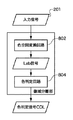
● スキャン画像の処理
スキャナ101は、原稿載置ガラス上に置かれた原稿の画像を読み取る。スキャナ101は、3ラインCCDにより原稿画像を画素ごとにディジタル的に読み取り、そのRGBカラー画像信号を出力する。入力画像処理部102は、スキャナ101が出力するカラー画像信号にシェーディング補正、CCDライン間補正、色補正など、周知の画像処理を行う。
Scanned Image Processing The
像域分離部103は、入力画像処理部102が出力する入力画像処理が施されたカラー画像信号に像域分離処理を行い、入力画像の画素ごとに、写真領域、文字領域、網点領域といった画像の特徴を検出し、像域ごとの属性を表すフラグデータを生成する。なお、詳細は後述する。
The image
入力画像処理部104は、像域分離部103が画素単位に出力する文字信号MOJIに基づき、入力画像処理部102が出力するカラー画像信号を画素単位に処理する。例えば文字領域(MOJI=‘1’)の高周波成分を強調して文字の鮮鋭度を強調したり、網点領域(MOJI=‘0’)に対しては所謂ローパスフィルタ処理を行ってディジタル画像に特有のモアレ成分を除去する、といった処理を画素単位に行う。
The input
入力画像処理部104で処理された画像データは画像メモリ105に、像域分離部103から出力されるフラグデータはフラグメモリ106に一時的に記憶される。このとき、画像メモリ105およびフラグメモリ106は、原稿画像の一頁分もしくは一頁のうちの予め決められたサイズ(バンド分)のデータを記憶する。
The image data processed by the input
データ圧縮部109は、画像メモリ105およびフラグメモリ106に一時記憶されたデータをデータ圧縮して記憶部110に格納する。記憶部110は、半導体メモリのような読み書きが高速なメモリであることが望ましい。データ圧縮部109は、画像データとフラグデータにそれぞれ異なるデータ圧縮を行う。すなわち、画像データは、JPEG圧縮のようなロッシー圧縮であるが、人間の視覚特性を考慮した画像の劣化が目立たない高能率の圧縮を施す。一方、フラグデータは、属性フラグ情報の欠落や変化が発生しないようにJBIG圧縮のようなロスレス圧縮を用いる。
The
このようにして、記憶部110には異なる圧縮が施された画像データおよびフラグデータが原稿画像の頁単位に記憶される。なお、記憶部110が記憶したデータまたはその一部を補助記憶部111に書き出す場合がある。補助記憶部111は、ハードディスクのような、読み書きの速度は若干遅いが大容量の記憶媒体が好ましい。補助記憶部111を用いることで、多数頁の原稿画像を効率的に記憶蓄積することができる。
In this way, the
記憶部110または補助記憶部111に記憶した画像をプリンタ117で印刷する場合、それら記憶部から画像データおよびフラグデータを読み出す。そして、それぞれデータ伸長部112で伸長し、伸長後の画像データおよびフラグデータをそれぞれ画像メモリ114およびフラグメモリ115に格納する。このとき、画素密度変換部113により、画像データの画素密度を変換する場合がある。例えば、記憶部110に蓄積した画像を拡大または縮小して印刷する場合、あるいは、蓄積した複数頁分の画像を合成して一枚の記録紙に印刷する場合などである。
When an image stored in the
図7は複数頁分の画像を合成して印刷する様子を示す図である。二つの画像501、502が記憶部110に記憶されていて、これらを合成して、原稿と同一サイズの記録紙503に印刷する。そのために、画像501の画像データを記憶部110から読み出して伸長し、画素密度変換部113により所定倍率に縮小する。さらに、回転処理部(不図示)で左に90度回転して、画像メモリ114の所定の領域(図7に符号504で示す領域に相当)に書き込む。次に、画像502の画像データを記憶部110から読み出し、同様に伸長、解像度変換、回転を行い画像メモリ114の所定の領域(図7に符号505で示す領域に相当)に書き込む。
FIG. 7 is a diagram illustrating a state in which images for a plurality of pages are combined and printed. Two
この際、画像501、502に対応するフラグデータも同様に、読み出し、伸長、解像度変換、回転してフラグメモリ115の対応する領域に書き込む。
At this time, the flag data corresponding to the
ここで、画像データの解像度変換とフラグデータの解像度変換はそれぞれ異なる手法を適用することが望ましい。例えば、画像データは線形補間法や双三次スプライン補間法などの周知の手法を適用する。また、フラグデータは最近傍処理法など二値データに適した解像度変換方法を用いることが望ましい。 Here, it is desirable to apply different methods to the resolution conversion of the image data and the resolution conversion of the flag data. For example, a known method such as a linear interpolation method or a bicubic spline interpolation method is applied to the image data. Further, it is desirable to use a resolution conversion method suitable for binary data such as nearest neighbor processing for the flag data.
出力画像処理部116は、詳細は後述するが、画像メモリ114およびフラグメモリ115に一時記憶された画像データおよびフラグデータが所定の記憶データ量に達すると、画像データおよびフラグデータを入力する。出力画像処理部116は、画像メモリ114から入力したRGB画像データを印刷用の画像信号に変換するための周知の画像処理、すなわちRGB→CMYK変換、ガンマ補正、二値化処理などを行い、処理後のCMYK画像信号を出力する。
Although details will be described later, the output
プリンタ117は、出力画像処理部116が出力するCMYK画像信号によって、レーザビームまたはインクジェットヘッドを駆動して記録紙に可視像を形成し、出力する。ここで、フラグメモリ115に記憶されたフラグデータは、出力画像処理部116の処理の切り替えに用いられる。
The
● 受信画像の処理
通信インタフェイス(I/F) 118は、ローカルエリアネットワーク(LAN)などの外部通信路119から印刷ジョブを受信する。当該印刷ジョブに付加される画像データとして代表的なものは、画像のレンダリングする画像を頁単位やバンド単位に記述する言語のデータである。以下では、このようなデータをPDL (Page Discription Language)データと呼ぶ。
Processing of Received Image A communication interface (I / F) 118 receives a print job from an
インタプリタ108は、通信I/F 118が受信したPDLデータをディスプレイリストと呼ばれる中間言語形式に変換する。
The
ラスタイメージプロセッサ(Raster Image Processor: RIP) 107は、ディスプレイリストに基づきレンダリングを行い、画像メモリ105にビットマップデータを形成する。そして、レンダリングしたビットマップデータの属性を表すフラグデータをフラグメモリ106に格納する。RIP 107は、PDLデータがその印刷単位(部品)ごとに保持する属性情報(写真、文字、グラフィックスなどの部品の属性を区別する情報)を参照して、レンダリングしたビットマップデータの各画素のフラグデータを生成する。つまり、文字部品の生成を示すPDLコマンドを入力すると、文字のビットマップデータを生成するとともに、文字画像に対応する領域(文字領域)のフラグデータとしてMOJI=‘1’をフラグメモリ106に格納する。なお、文字領域以外はMOJI=‘0’をフラグメモリ106に格納する。
A raster image processor (RIP) 107 performs rendering based on the display list and forms bitmap data in the
以降の処理は、スキャン画像の処理と同じであるから、説明を省略する。 Subsequent processing is the same as that of the scanned image, and thus description thereof is omitted.
[像域分離部]
以下では、像域分離処理について、その概念と一例を説明する。なお、下記の説明は像域属性の抽出方法の一例であり、像域分離処理は下記に限定されるものではない。
[Image separation part]
Hereinafter, the concept and an example of the image area separation processing will be described. The following description is an example of an image area attribute extraction method, and the image area separation processing is not limited to the following.
像域分離処理は、画像の特徴に応じた最適な画像処理を施すために、画像の特徴を抽出して像域属性を示す信号(フラグデータ)を生成する。原稿画像には、例えば、連続階調のフルカラー写真領域、黒一色の文字領域、あるいは、新聞などの印刷に代表される網点印刷領域など、様々な画像領域が混在している。これら特徴が異なる領域に一律に、同一の画像処理を施すと、その処理結果として一般に好ましい画質が得られない場合が多い。 In the image area separation process, in order to perform optimal image processing according to the image characteristics, the image characteristics are extracted to generate a signal (flag data) indicating the image area attribute. The original image includes various image areas such as a continuous tone full-color photographic area, a black-colored character area, or a halftone dot printing area typified by printing on newspapers. When the same image processing is uniformly performed on regions having different features, generally, a preferable image quality is often not obtained as a result of the processing.
そこで、入力画像処理部102が出力するカラー画像信号を用いて、原稿画像に含まれる画像データの属性を検出し、それを識別するためのフラグデータを生成する。
Therefore, the color image signal output from the input
図2は像域分離部103の文字属性の画素を検出する構成例を示すブロック図である。
FIG. 2 is a block diagram illustrating a configuration example for detecting a pixel having a character attribute of the image
入力信号(カラー画像信号)201は、平均濃度演算部202およびエッジ強調処理部203に入力される。平均濃度演算部202は、入力信号201の注目画素を中心とするM×N画素の領域(MとNは自然数)の平均値AVEを出力する。一方、エッジ強調処理部203は、注目画素の周辺領域(例えばM×N画素領域)を参照して注目画素にエッジ強調処理を行い、強度が異なる二種類のエッジ強調信号EDG1とEDG2を出力する。これらの信号は、網点判定部204およびエッジ判定部205に入力される。
An input signal (color image signal) 201 is input to an average
図3は平均値AVEおよびエッジ強調信号EDG1を入力する網点判定部204の構成例を示すブロック図である。
FIG. 3 is a block diagram illustrating a configuration example of the halftone
二値化処理部401は、式(1)に示すように、エッジ強調信号EDG1にある係数A(実数)を乗算した後、平均値AVEと比較した結果に基づき二値化信号を生成する。
A×EDG1 < AVE ならば 二値化信号 =‘1’
A×EDG1 ≧ AVE ならば 二値化信号 =‘0’ …(1)
As shown in Equation (1), the
If A × EDG1 <AVE, binarized signal = '1'
If A x EDG1 ≥ AVE, binarized signal = '0'… (1)
二値化処理部401によって画素ごとに得られる二値化信号は、1×1孤立量算出部411、2×2孤立量算出部412、3×3孤立量算出部413、4×4孤立量算出部414に入力される。孤立量算出部411〜414は、二値化処理の結果を用いて、注目画素がどの程度孤立しているかを判断する。
The binarized signal obtained for each pixel by the
例えば、1×1孤立量算出部411が行う孤立量の算出は、注目画素を中心位置とする3×3画素領域の二値化信号を参照し、その値が縦、横または斜め方向に‘0’‘1’‘0’と変化する場合、その方向の孤立量を「1」とする。そして、縦、横(各一方向)および斜め(ニ方向)の四方向の合計を注目画素の孤立量として出力する。従って、孤立度が高い画素の場合は孤立量「4」に、孤立していない画素の場合は孤立量「0」になる。なお、網点ドットが一画素で構成される場合、すなわち、低濃度領域の網点画素または線数の高い網点に対して孤立量が比較的大きくなるという特徴を有する。
For example, the isolation amount calculation performed by the 1 × 1 isolation
同様に、2×2孤立量算出部412、3×3孤立量算出部413、4×4孤立量算出部414も、所定の二値化画素パターンとの比較により、注目画素の孤立量を出力する。
Similarly, the 2 × 2 isolation
1×1孤立量加算部421から4×4孤立量加算部424はそれぞれ、1×1孤立量算出部411から4×4孤立量算出部414でそれぞれ算出された孤立量を所定領域で加算する。例えば、1×1孤立量加算部421では、9×9画素領域の孤立量を加算する。
The 1 × 1 isolated
網点判定部431は、1×1孤立量加算部421から4×4孤立量加算部424で算出された加算値それぞれについて閾値処理を行い、それらの結果から多数決や論理演算などの処理を経て網点信号AMIを出力する。なお、網点判定部431は、注目画素が網点を構成すると判定した場合、網点信号AMI=‘1’を出力する。
The halftone
図4は平均値AVEおよびエッジ強調信号EDG2を入力するエッジ判定部205の構成例を示すブロック図である。
FIG. 4 is a block diagram illustrating a configuration example of the
濃度差判定部301は、式(2)に示すように、エッジ強調信号EDG2にある係数B(実数)を乗算した後、平均値AVEと比較した結果に基づき濃度差信号を生成する。
C < AVE - B×EDG2 < D ならば 濃度差信号 =‘1’
上記以外ならば 濃度差信号 =‘0’ …(2)
ここで、C、Dは実数または整数
As shown in Expression (2), the density
If C <AVE-B x EDG2 <D, density difference signal = '1'
Otherwise, density difference signal = '0'… (2)
Where C and D are real numbers or integers
つまり、エッジ強調信号EDG2の値と、その周辺領域の値(平均値AVE)の差に応じた濃度差信号を出力する。 That is, a density difference signal corresponding to the difference between the value of the edge enhancement signal EDG2 and the value of the surrounding area (average value AVE) is output.
孤立判定部302は、濃度差信号を入力して孤立点を除去する。例えば、7×7画素領域で濃度差信号を参照し、最外郭の画素位置に値‘1’の濃度差信号が存在しない場合、内側の5×5画素領域の濃度差信号の値を強制的に‘0’にすることで孤立点を除去する。なお、孤立判定部302が出力する孤立点除去後の濃度差信号を孤立判定信号と呼ぶ。
The
補正処理部303は、孤立判定信号を入力し、孤立判定信号の不連続部分を補正したエッジ信号EDGEを出力する。例えば、3×3画素領域で孤立点判定信号を参照し、領域の中央の注目画素を挟む画素(上下、左右または斜め)の孤立判定信号の値が‘1’で、注目画素の孤立判定信号の値が‘0’の場合、注目画素の孤立判定信号の値を‘1’に補正する。この処理によって、線画や文字のエッジ領域において孤立判定信号が欠けた欠損部分を修復し、線画や文字のエッジ領域の連続性を増した滑らかなエッジ信号EDGEを生成する。なお、補正処理部303は、エッジ領域ならばエッジ信号EDGE=‘1’を出力する。
The
次に、図2に示す文字判定部206は、網点判定部204が出力する網点信号AMI、および、エッジ判定部205が出力するエッジ信号EDGEを入力して、AMI=‘0’かつEDGE=‘1’である画素を示す文字信号MOJIを出力する。
Next, the
図5は像域分離部103のカラー属性の画素を検出する構成例を示すブロック図である。
FIG. 5 is a block diagram illustrating a configuration example for detecting pixels having color attributes in the image
入力信号(カラー画像信号)201は、色空間変換回路802に入力されて例えばLab信号に変換される。色判定回路804は、Lab信号を入力して色判定信号COLを出力する。
An input signal (color image signal) 201 is input to the color
画像データのある画素がカラー画素か否かを判別するには、画素の色度を色空間上にマッピングすることで容易に判別される。一例として、Lab色空間を例に説明する。 In order to determine whether or not a pixel having image data is a color pixel, it is easily determined by mapping the chromaticity of the pixel on the color space. As an example, a Lab color space will be described as an example.
Lab色空間とは、均等知覚色空間として1976年にCIE(Commission Internationale de l'Eclairage:国際照明委員会)より提案された色空間である。Lは明度(明るさ)、aは赤色から緑色への色度、bは青色から黄色への色度を表している。Lab色空間は、三次元色空間における変化と、その変化によって受ける視覚の色変化の印象が比例するよう構成されているため、精度の高い色判別が可能になる。 The Lab color space is a color space proposed by the CIE (Commission Internationale de l'Eclairage) in 1976 as a uniform perceptual color space. L represents lightness (brightness), a represents chromaticity from red to green, and b represents chromaticity from blue to yellow. The Lab color space is configured so that the change in the three-dimensional color space is proportional to the impression of the visual color change caused by the change, so that highly accurate color discrimination is possible.
式(3)にRGB信号をLab信号に変換する例を示す。通常、RGB信号から一旦XYZ三刺激値を算出した後、XZY三刺激値からLab信号値を導出する。なお、式(3)の係数は、デバイスに依存するため、この限りではない。
X = 0.412391×R + 0.357584×G + 0.180481×B
Y = 0.212639×R + 0.715169×G + 0.072192×B
Z = 0.019331×R + 0.119195×G + 0.950532×B
L* = 116(Y/Y0)1/3 - 16
a* = 500{(X/X0)1/3 - (Y/Y0)1/3}
b* = 200{(Y/Y0)1/3 - (Z/Z0)1/3} …(3)
ここで、X0、Y0、Z0は標準光における三刺激値
Formula (3) shows an example of converting RGB signals into Lab signals. Usually, once the XYZ tristimulus values are calculated from the RGB signals, the Lab signal values are derived from the XZY tristimulus values. Note that the coefficient of Equation (3) is not limited to this because it depends on the device.
X = 0.412391 × R + 0.357584 × G + 0.180481 × B
Y = 0.212639 × R + 0.715169 × G + 0.072192 × B
Z = 0.019331 × R + 0.119195 × G + 0.950532 × B
L * = 116 (Y / Y0) 1 /3-16
a * = 500 {(X / X0) 1 /3-(Y / Y0) 1/3 }
b * = 200 {(Y / Y0) 1 /3-(Z / Z0) 1/3 }… (3)
Where X0, Y0 and Z0 are tristimulus values in standard light
式(3)で算出した各画素のab値を直交座標系にマッピングし、その画素が有彩色か無彩色かを判定する。図6はa*b*平面を表す図で、有彩色か無彩色かを例えば彩度を基準に判定する場合、a*軸とb*軸の交点、つまり原点は色成分がゼロの点であり、原点から離れる(a*および/またはb*の値が大きくなる)に連れて彩度は大きくなる。従って、原点からの距離を示す閾値を設定して有彩色か無彩色かを判定すればよい。つまり、図6に示す斜線部903を無彩色の領域と仮定すると、ある画素のab値が、斜線部903の内側の点904にあれば当該画素を無彩色と判定し、斜線部903の外側の点905にあれば当該画素は有彩色と判定すればよい。
The ab value of each pixel calculated by Expression (3) is mapped to an orthogonal coordinate system to determine whether the pixel is a chromatic color or an achromatic color. Figure 6 shows the a * b * plane.When determining whether chromatic or achromatic color is based on saturation, for example, the intersection of the a * axis and b * axis, that is, the origin is the point where the color component is zero. Yes, the saturation increases with distance from the origin (the value of a * and / or b * increases ) . Therefore, a threshold value indicating the distance from the origin may be set to determine whether the color is chromatic or achromatic. That is, assuming that the hatched
以上のような手法によって、注目画素が有彩色か無彩色か、言い換えればカラー属性の画素か否かを判定することができる。 By the method as described above, it can be determined whether the pixel of interest is a chromatic color or an achromatic color, in other words, a pixel having a color attribute.
なお、色度の算出をLabを用いて説明したが、これに限るものではない。また、計算量を減らすため、簡易的な変換式に置き換えてもかまわない。 In addition, although calculation of chromaticity was demonstrated using Lab, it is not restricted to this. In order to reduce the amount of calculation, a simple conversion formula may be used.
[出力画像処理部]
図8は出力画像処理部116の構成例を示すブロック図である。
[Output image processing section]
FIG. 8 is a block diagram illustrating a configuration example of the output
RGB→CMYK変換部601、602は画像メモリ114からRGBカラー画像データを入力し、それぞれ独立にCMYK変換を行う。セレクタ603は、フラグメモリ115から入力されるフラグデータに従い、画素単位に、RGB→CMYK変換部601の出力またはRGB→CMYK変換部602の出力を選択する。
The RGB →
RGB→CMYK変換部601には文字領域用の変換係数(または変換テーブル)が設定され、RGB→CMYK変換部602には文字領域以外用の変換係数(または変換テーブル)が設定される。従って、例えば黒文字画素(文字領域(MOJI=‘1’)かつ非カラー画素(COL=‘0’))の場合、セレクタ603により黒トナーまたは黒インクのみで再現するような変換係数が選択される。言い換えれば画像データが無彩色の場合はC、M、Y=0になるような係数または変換テーブルが適用されたCMYK画像信号が選択される。また、文字領域以外(MOJI=‘0’)の場合、セレクタ603により、無彩色(COL=‘0’)でもC、M、Yは0にならず、深みのある黒色を再現するような信号を生成する係数または変換テーブルが適用されたCMYK画像信号が選択される。このようにすれば、例えば文字領域と写真領域などその他の領域でCMYK画像信号の生成方法を変更して、出力画像の画質を向上させることができる。
A conversion coefficient (or conversion table) for a character area is set in the RGB →
次に、セレクタ603の出力は、ガンマ補正部604および誤差拡散処理部606の処理系統、並びに、ガンマ補正部605およびディザ処理部607の処理系統に入力される。セレクタ608は、フラグメモリ115から入力されるフラグデータに従い、画素単位に、誤差拡散処理部606の出力またはディザ処理部607の出力を選択する。
Next, the output of the
従って、セレクタ608により、文字領域やグラフ領域は出力画像の鮮鋭度を優先して誤差拡散処理部606の出力を選択し、写真領域や網点領域は階調性を重視してディザ処理部607の出力を選択することで、出力画像の画質を向上させることができる。
Accordingly, the
[偽造判定処理部]
偽造判定処理部120は、紙幣など複写が禁止されている原稿(以下「特定原稿」と呼ぶ)の複写を防ぐための偽造判定処理を行う。当該処理には幾つかの方法があるが、代表的な方法はパターンマッチングである。特定原稿の形状や色などの特徴、あるいは、原稿画像に意図的に埋め込まれた特徴を抽出して、予め記憶する情報との類似度から特定原稿か否かを判定する。
[Forgery determination processing section]
The forgery
図9は偽造判定処理部120の構成例を示すブロック図である。
FIG. 9 is a block diagram illustrating a configuration example of the forgery
偽造判定処理部120は、入力画像処理部102からスキャン画像を、または、RIP 107からビットマップデータを判定用のRGB画像信号として入力する。二値化部701は、メモリ702に記憶された閾値により入力RGB画像信号を二値化する。なお、二値化閾値は可変である。
The forgery
特徴抽出部703は、メモリ704に記憶された特徴情報に類似する部位を二値化後の画像から切り出す。メモリ704は、特定原稿の特徴を表す形状、色、特定のマーク、原稿画像に意図的に埋め込まれる特徴などを記憶する。
The
パターンマッチング部705は、特徴抽出部703が切り出した画像がメモリ706に記憶されたパターンにマッチする場合、その結果を制御部707に通知する。制御部707は、パターンがマッチした旨の通知を受けると、例えば、画像メモリ105に格納されたスキャン画像または受信画像の削除、あるいは、パターンがマッチした画像部分を黒べたに塗り潰すなどにより、特定原稿の複写またはプリントを阻止する。
If the image cut out by the
なお、制御部707は、上述した各部を制御して装置全体の動作を制御するワンチップCPUなどで構成される。また、上記では、複写機等で行う偽造判定処理の一例を説明したが、これに限るものではない。
Note that the
[網点領域の検出]
上記の画像処理システムは、像域分離処理を用いて画像の特徴を抽出し、画像に含まれる像域に応じて最適な画像処理を施す。例えば、画像中の写真部と文字部を切り分け、写真部には色調や階調性を重視する写真用の画像処理を、文字部には鮮鋭度を重視する文字用の画像処理を施し、出力画像の画像品位を向上する。また、画像の色成分を検出して、無彩色の文字などは黒単色で印刷し、画像品位の向上を図る。
[Detection of halftone dot area]
The image processing system extracts image features using image area separation processing and performs optimum image processing according to the image area included in the image. For example, the photographic part and character part in the image are separated, the photographic part is subjected to image processing that emphasizes color tone and gradation, and the character part is subjected to image processing that emphasizes sharpness and output. Improve the image quality of the image. In addition, the color component of the image is detected, and achromatic characters are printed in a single black color to improve the image quality.
しかし、網点領域を孤立量という概念で検出すれば、低濃度部の網点領域の検出精度は充分とは言えない。網点領域内に文字のエッジ、ごみや汚れの画像があると孤立量が低下し、その結果、網点領域の検出精度が低下する。 However, if the halftone dot region is detected based on the concept of an isolated amount, the detection accuracy of the low density portion halftone dot region cannot be said to be sufficient. If there is an image of character edges, dust or dirt in the halftone dot area, the amount of isolation decreases, and as a result, the detection accuracy of the halftone dot area decreases.
図10は網点領域の検出を説明する図で、図図(a)は通常の網点領域を、同(b)は網点領域内に文字のエッジが存在する例を示し、各升は一画素を表す。また、説明を簡単にするため、孤立量は1ビットとし、図10に示す黒画素の孤立量は‘1’、白画素の孤立量は‘0’とする。 FIG. 10 is a diagram for explaining detection of a halftone dot region. FIG. 10 (a) shows a normal halftone dot region, FIG. 10 (b) shows an example in which a character edge exists in the halftone dot region, Represents one pixel. For the sake of simplicity, the isolated amount is assumed to be 1 bit, the isolated amount of black pixels shown in FIG. 10 is ‘1’, and the isolated amount of white pixels is ‘0’.
例えば9×9画素領域2402で孤立量を加算するとして、領域2402内の孤立画素が5%を超える(五画素以上)ならば注目画素は網点領域にあり、5%以下(四画素以下)ならば注目画素は網点領域にはないと規定する。
For example, if the isolated amount is added in the 9 × 9
図10(a)に示す通常の網点領域では、注目画素2401を中心とする9×9画素領域2402の孤立量加算値は12画素になり、上記の規定から注目画素は網点領域にあると判定される。一方、図10(b)に示す文字のエッジが存在する場合は、同じ条件で孤立量を加算すると、文字エッジ2411の影響を受けて孤立量が減少する。その結果、加算値は四画素になり、注目画素は網点領域にないと判定される。
In the normal halftone dot region shown in FIG. 10 (a), the isolated amount addition value of the 9 × 9
この問題を解決するために、(1) 網点判定の閾値を網点を抽出し易い方向に設定する、(2) 孤立量を積算するエリアを拡大して判定のラチチュードを広げる、などの方法をとる。しかし、(1)の場合は網点領域の検出精度は向上するが、同時に、網点領域ではないところまで網点領域と判定する誤判定が増大する。また、(2)の場合、参照エリアを拡大すれば、本来、網点領域と判定すべきではない網点領域の周辺部分まで網点領域と判定してしまう。 To solve this problem, (1) Set the threshold value for halftone dot determination in a direction that makes it easy to extract halftone dots. (2) Expand the area for accumulating the isolated amount to widen the determination latitude. Take. However, in the case of (1), the accuracy of detection of the halftone dot area is improved, but at the same time, misjudgment that determines that it is not a halftone dot area increases. In the case of (2), if the reference area is enlarged, it is determined that the area surrounding the halftone dot area that should not be determined as the halftone dot area is the halftone dot area.
図11は孤立量を積算するエリアを拡大した場合の問題を説明する図で、同図(a)はエリア拡大前、同(b)はエリア拡大後を示している。 FIG. 11 is a diagram for explaining a problem when the area for integrating the isolated amount is enlarged. FIG. 11 (a) shows the area before the area expansion, and FIG. 11 (b) shows the area after the area expansion.
図11(a)に示すエリア拡大前の9×9画素領域2503の孤立量加算値は0だから、注目画素2502は網点領域にはないとは判定される。一方、図11(b)に示すエリア拡大後の15×15画素領域2513の孤立量加算値は12画素になり、5%(11画素)を超え、注目画素2512は網点領域にあると判定される。
Since the isolated amount addition value of the 9 × 9
以下では、網点領域内に文字のエッジ、ごみや汚れの画像がある場合の網点領域の検出精度を向上し、上記の弊害が発生しない網点領域の検出方法を説明する。 In the following, a method for detecting a halftone dot area in which the halftone dot area detection accuracy is improved when there is an image of a character edge, dust or dirt in the halftone dot area will be described.
[像域分離処理]
図12は網点領域の検出精度の向上を図った像域分離部103の構成例を示すブロック図である。
[Image area separation processing]
FIG. 12 is a block diagram showing a configuration example of the image
入力信号201は、網点判定を行う網点判定部1002と、文字/線画判定を行う文字/線画判定部1003に入力される。ビット合成部1004は、各判定部の判定結果を一つの信号に合成した属性フラグを生成し出力する。この属性フラグに基づき、画像に含まれる像域に最適な画像処理を施すことができる。
The
●文字/線画判定部
図13は文字/線画判定部1003の構成例を示すブロック図である。
Character / Line Drawing Determination Unit FIG. 13 is a block diagram showing a configuration example of the character / line
入力信号201は、エッジ強調処理を行うエッジ強調部1102に入力される。エッジ強調部1102は、画像データの所望の周波数成分を強調、抽出するディジタルフィルタ処理を行う。なお、フィルタとしては、ラプラシアンフィルタのような二次微分フィルタなどが代表的な例である。
The
エッジ強調部1102が出力するエッジ強調信号は、閾値判定部1103と1104に入力される。エッジ強調部1102によって二次微分フィルタ処理された信号は正負の信号値をもつので、閾値判定部1103には正の値の閾値を、閾値判定部1104には負の値の閾値を設定する。
The edge enhancement signal output from the
例えば、図14(a)に示す白い下地1503上の黒い文字1502のエッジ部を矢印1510に沿って走査した入力信号201の信号値の変化は図14(b)に示すようになる。つまり、エッジ境界1501の手前(文字1502の内部)は暗く信号値は低いが、エッジ境界1501を過ぎると、下地1503は明るく信号値は急激に上昇する。このような変化を示す入力信号201を二次微分フィルタ処理すると、その信号値は、図14(c)に示すように、エッジ境界1501の手前では正の値をとり、エッジ境界1501を過ぎると負の値をとる。つまり、閾値判定部1103は、エッジ強調信号が正の閾値を超えると、文字エッジの内側を示す内エッジ信号=‘1’を出力する。また、閾値判定部1104は、エッジ強調信号が負の閾値を下回ると、文字エッジの外側を示す外エッジ信号=‘1’を出力する。
For example, the change in the signal value of the
なお、図14には一方向の走査しか示さないが、少なくとも直交する方向の走査も行い、少なくとも二方向のエッジ検出結果の論理和をエッジ信号にする。 Although FIG. 14 shows only scanning in one direction, scanning in at least orthogonal directions is also performed, and the logical sum of edge detection results in at least two directions is used as an edge signal.
閾値判定部1103が出力する内エッジ信号は、エリア積算部1105へ入力される。また、閾値判定部1104が出力する外エッジ信号は、エリア積算部1106へ入力される。エリア積算部1105、1106は、例えば、注目画素とその周辺の3×3画素領域の判定信号=‘1’をカウントする。
The inner edge signal output from the
閾値判定部1107、1108はそれぞれ、エリア積算部1105、1106が出力するカウント値と閾値を比較して判定結果を出力する。例えば、閾値として2が設定されている場合、閾値判定部1107は、入力されるカウント値が2以上、つまり3×3画素領域に内エッジと判定された画素が二つ以上ある場合に判定信号=‘1’を出力する。同様に、閾値判定部1108は、3×3画素領域に外エッジと判定された画素が二つ以上ある場合に判定信号=‘1’を出力する。
The threshold
図15は文字/線画判定部1003の各判定を説明する図で、同図(a)は入力信号201を示し、白い下地に黒文字のエッジが存在する様子を示している。
FIG. 15 is a diagram for explaining each determination of the character / line
入力信号201をエッジ強調した信号を閾値判定部1103で判定すると、図15(b)に示す内エッジ信号(斜線で示す部分が‘1’)が得られる。内エッジ信号を3×3画素領域でエリア積算(カウント)し、閾値判定部1107で判定すると、図15(c)に示す判定信号が得られる。つまり、内エッジ信号が拡大される(「内エッジ拡大信号」と呼ぶ)。
When the threshold
一方、入力信号201をエッジ強調した信号を閾値判定部1104で判定すると、図15(d)に示す外エッジ信号が得られる。外エッジ信号を3×3画素領域でエリア積算(カウント)し、閾値判定部1108で判定すると、図15(e)に示す判定信号が得られる。つまり、外エッジ信号が拡大される(「外エッジ拡大信号」と呼ぶ)。
On the other hand, when the threshold
ルックアップテーブル(LUT) 1109は、閾値判定部1103、1107、1108の判定信号を入力し、下記の論理に従い文字信号を出力する。
内エッジ判定信号=‘1’→ 文字信号=‘1’
内エッジ判定信号=‘0’で、
内エッジ拡大信号=‘1’かつ外エッジ拡大信号=‘0’→ 文字信号=‘1’
上記に該当しない → 文字信号=‘0’
A lookup table (LUT) 1109 receives the determination signals from the
Inner edge judgment signal = '1' → Character signal = '1'
When the inner edge judgment signal = '0',
Inner edge enlargement signal = '1' and outer edge enlargement signal = '0' → Text signal = '1'
Not applicable to the above → Character signal = '0'
図16は上記の論理に対応するLUT 1109のテーブルの構成を示す図である。
FIG. 16 is a diagram showing the configuration of a table of the
つまり、LUT 1109は、内エッジ判定、内エッジ判定のエリア積算判定、外エッジ判定のエリア積算判定の結果に応じて、図15(f)に示すように、文字信号を出力する。
That is, the
●網点判定部
図17は網点判定部1002の構成例を示すブロック図である。
Halftone Point Determination Unit FIG. 17 is a block diagram showing a configuration example of the halftone
入力信号201は、エッジ強調部1102と同様のエッジ強調処理を行うエッジ強調部1202に入力される。
The
エッジ強調部1202が出力するエッジ強調信号は、閾値判定部1203と1204に入力される。エッジ強調部1202によって二次微分フィルタ処理された信号は正負の信号値をもつので、閾値判定部1203には正の値の閾値を、閾値判定部1204には負の値の閾値を設定する。
The edge enhancement signal output by the
例えば、図18(a)に示す白い下地1603上の網点1602のエッジ部を矢印1610に沿って走査した入力信号201の信号値の変化は図18(b)に示すようになる。つまり、エッジ境界1601の手前(網点1602の内部)は暗く信号値は低いが、エッジ境界1601を過ぎると、下地1603は明るく信号値は急激に上昇する。このような変化を示す入力信号201を二次微分フィルタ処理すると、その信号値は、図18(c)に示すように、エッジ境界1601の手前では正の値をとり、エッジ境界1601を過ぎると負の値をとる。つまり、閾値判定部1203は、エッジ強調信号が正の閾値を超えると、文字エッジの内側を示す内エッジ信号=‘1’を出力する。また、閾値判定部1204は、エッジ強調信号が負の閾値を下回ると、文字エッジの外側を示す外エッジ信号=‘1’を出力する。
For example, the change in the signal value of the
なお、図18には一方向の走査しか示さないが、少なくとも直交する方向の走査も行い、少なくとも二方向のエッジ検出結果の論理和をエッジ信号にする。 FIG. 18 shows only scanning in one direction, but scanning in at least orthogonal directions is also performed, and the logical sum of edge detection results in at least two directions is used as an edge signal.
閾値判定部1203が出力する内エッジ信号は、孤立量判定部1205に入力される。また、閾値判定部1204が出力する外エッジ信号は、孤立量判定部1206に入力される。
The inner edge signal output from the
孤立量判定部1205は、内エッジ信号についてパターンマッチングを行い、網点ドットを検出する。網点画像には低線数のものから高線数のものまであり、画像によって網点ドットのサイズや間隔が異なる。そこで、どのような線数の網点も検出できるようにするため、複数のパターンを用いてパターンマッチングを行う。低線数の網点画像に対しては、大きいパターンを使用してパターンマッチングを行い網点ドットを検出する。高線数の網点画像に対しては、小さいパターンを使用してパターンマッチングを行い網点ドットを検出する。また、網点ドットは濃度によってもその形状が変化するため、それに対応できるよう判定レベルを調整可能にする。
The isolation
図19は孤立量判定用のマッチングパターンを説明する図で、4×4画素領域でパターンマッチングする例を示す。 FIG. 19 is a diagram for explaining a matching pattern for determining an isolated amount, and shows an example of pattern matching in a 4 × 4 pixel region.
図19(a)は4×4画素領域の内エッジ信号を示し、内エッジ信号=‘1’の画素は、符号1702で示す四画素(黒色の画素)である。残る画素は、内エッジ信号=‘0’の画素である。なお、記号*を付した画素1701は注目画素である。
FIG. 19A shows the inner edge signal of the 4 × 4 pixel region, and the pixels having the inner edge signal = “1” are four pixels (black pixels) denoted by
図19(b)は4×4画素のマッチングパターンの一例を示す。図19(b)において、黒色の四画素1712は内エッジ信号=‘1’を、白色の八画素1713は内エッジ信号=‘0’を、斜線を付した四画素1714はどちらでも構わない画素(Don't Care:以後「DC」と表記する)である。このパターンを基本に、黒色の画素1712と白色の画素1713それぞれのマッチング度合いを調整可能にして、判定レベルを調整する。
FIG. 19 (b) shows an example of a 4 × 4 pixel matching pattern. In FIG. 19 (b), the black four
図20は孤立量判定を説明する図で、4×4画素領域の内エッジ信号と注目画素1701の判定結果の例を示している。
FIG. 20 is a diagram for explaining the isolation amount determination, and shows an example of the determination result of the inner edge signal in the 4 × 4 pixel region and the
図20(a)〜(c)に示すように、注目画素1701の孤立量判定信号が‘1’になるのは次の条件である。
黒色の四画素1712にマッチする画素(内エッジ信号=‘1’の画素)が三以上
かつ
白色の八画素1713にマッチする画素(内エッジ信号=‘0’の画素)が六以上
As shown in FIGS. 20A to 20C, the isolation amount determination signal of the
Three or more pixels that match the four black pixels 1712 (inner edge signal = '1')
And there are 6 or more pixels that match 8 white pixels 1713 (inner edge signal = '0')
上記の条件を満たさない場合、同図(d)に示すように、注目画素1701の孤立量判定信号=‘0’にする。上記のパターンにマッチする画素の数がマッチング度合であり、これを調整することで判定レベルを調整する。
If the above condition is not satisfied, the isolated amount determination signal of the
孤立量判定部1205は、このようなパターンマッチングを複数のパターンを用いて行う。また、外エッジ信号の孤立量判定を行う孤立量判定部1206も、孤立量判定部1205と同様のパターンマッチングを行う。その際、マッチングパターンや判定レベルは任意に調整し設定することができる。
The isolation
OR処理部1207、1208は、孤立量判定部1205、1206が出力する孤立量判定信号の両方を入力する。OR処理1207は例えば3×3画素領域内で孤立量判定信号の論理和をとり、一画素でも‘1’があれば注目画素の判定信号=‘1’にする。
The OR
図21はOR処理部1207、1208の処理を説明する図である。
FIG. 21 is a diagram for explaining the processing of the
図21(a)は3×3画素領域で注目画素の孤立量判定信号だけが‘1’の場合で、OR処理後の注目画素の信号(以下「OR信号」と呼ぶ)は‘1’になる。同図(b)は注目画素の孤立量判定信号は‘0’であるが、領域内に‘1’の画素があり、OR処理後の注目画素のOR信号は‘1’になる。同図(c)は注目画素の孤立量判定信号だけが‘0’で、他の画素が‘1’であるから、OR処理後の注目画素のOR信号は‘1’になる。 FIG. 21 (a) shows a case where only the isolation amount determination signal of the target pixel is “1” in the 3 × 3 pixel region, and the signal of the target pixel after OR processing (hereinafter referred to as “OR signal”) is “1”. Become. In FIG. 5B, the isolation amount determination signal of the target pixel is “0”, but there is a “1” pixel in the region, and the OR signal of the target pixel after OR processing is “1”. In FIG. 6C, only the isolation amount determination signal of the target pixel is “0” and the other pixels are “1”, so the OR signal of the target pixel after OR processing is “1”.
OR処理部1207、1208が出力するOR信号は、積算処理部1209、1210、閾値判定部1211、1212、網点判定部1213、1214を経て網点信号1と網点信号2になる。
The OR signals output from the
図22は積算処理部1209(または1210)、閾値判定部1211(または1212)、網点判定部1213(または1214)によって網点信号1または2を生成する過程を説明する図である。
FIG. 22 is a diagram for explaining a process of generating
まず、OR処理信号2001は、複数のエリアで積算される。例えば、積算処理部2011は9×9画素領域で、積算処理部2012は15×15画素領域で、積算処理部2013は21×21画素領域でOR処理信号=‘1’の画素数をカウント(積算)する。各積算処理部が出力するカウント信号はそれぞれ、9×9画素領域で判定を行う閾値判定部2021、15×15画素領域で判定を行う閾値判定部2022、21×21画素領域で判定を行う閾値判定部2023に入力される。なお、閾値判定部の閾値は、それぞれ設定することができる。網点判定部2031は、各閾値判定部が出力する判定信号を入力し、網点信号を出力する。
First, the
図23は積算処理部2011〜2013の処理を説明する図で、低濃度網点部のOR処理信号を、OR処理信号=‘1’を黒色の画素で、OR処理信号=‘0’を白色の画素で示す。ここでは三つの積算エリアでOR処理信号を積算する例を説明するが、三つの積算エリアに限られるわけではない。
FIG. 23 is a diagram for explaining the processing of the
図23に示す状態の、注目画素2101を中心とするOR処理信号を、9×9画素領域2102、15×15画素領域2103、21×21画素領域2104それぞれにおいて積算(OR処理信号=‘1’の画素をカウント)すると、その結果は次のようになる。
9×9画素領域2102は12画素
15×15画素領域2103は40画素
21×21画素領域2104は76画素
In the state shown in FIG. 23, OR processing signals centered on the
9 × 9
15 × 15
21 × 21
閾値判定部2021〜2023は、領域内のOR処理信号=‘1’の画素の面積が例えば5%を超える場合は注目画素2101は網点領域にあり、例えば5%以下の場合は注目画素2101は網点領域にはないと判定する。従って、各積算エリアを網点領域と判定する閾値は次のようになる。
9×9画素領域の閾値は 5画素以上
15×15画素領域の閾値は12画素以上
21×21画素領域の閾値は23画素以上
The threshold
9 × 9 pixel area threshold is 5 pixels or more
15 × 15 pixel area threshold is 12 pixels or more
The threshold of the 21 × 21 pixel area is 23 pixels or more
従って、上記の積算結果は次のように判定される。
9×9画素領域2102は12画素> 5画素 → 網点領域
15×15画素領域2103は40画素>12画素 → 網点領域
21×21画素領域2104は76画素>23画素 → 網点領域
Therefore, the above integration result is determined as follows.
9 × 9
15 × 15
21 x 21
図24は網点判定部2031の処理を説明する図である。
FIG. 24 is a diagram for explaining the processing of the halftone
網点判定部2031は、各積算エリアの判定結果に基づき、注目画素2101が網点領域にあるか否かを判定する。まず、各積算エリアの判定結果をペアリングする。例えば、9×9画素領域2102と15×15画素領域2103の判定結果で一組、15×15画素領域2103と21×21画素領域2104の判定結果でもう一組のようにペアリングし、各組の論理積をとる。そして、論理積の結果を論理和して網点信号にする。上の例は、すべての積算エリアが網点領域と判定されているから、論理積、論理和の結果、網点信号=‘1’になる。
The halftone
図25は低濃度部の網点領域に文字エッジがある場合の積算処理部2011〜2013の処理を説明する図である。
FIG. 25 is a diagram for explaining the processing of the
図25に示す状態の、注目画素2101を中心とするOR処理信号を、図23の説明と同様に、各積算エリア2102〜2104それぞれにおいて積算すると、その結果は次のようになる。
9×9画素領域2102は 4画素
15×15画素領域2103は32画素
21×21画素領域2104は60画素
When the OR processing signal centered on the
9 × 9
15 x 15
21 × 21
従って、閾値判定部2021〜2023の判定結果は次のようになる。
9×9画素領域2102は 4画素< 5画素 → 非網点領域
15×15画素領域2103は32画素>12画素 → 網点領域
21×21画素領域2104は60画素>23画素 → 網点領域
Therefore, the determination results of the
9 × 9
15 x 15
21 x 21
網点判定部2031は、図24に示す論理演算を行い、9×9画素領域2102と15×15画素領域2103の組の論理積の結果は‘0’になる。一方、15×15画素領域2103と21×21画素領域2104の組の論理積の結果は‘1’になるから、それらの論理和の結果、網点信号=‘1’になる。
The halftone
このように、一つの積算エリア(この場合は9×9画素領域2102)の判定結果は非網点領域になる。言い換えれば、文字や線画を含む網点領域は、積算エリアのサイズや閾値によって非網点領域と判定されることがある。そこで、サイズが異なる複数の積算エリアと、それぞれ異なる閾値を用いることで、文字や線画を含む網点領域を、正しく網点領域として検出することができる。 As described above, the determination result of one integration area (in this case, the 9 × 9 pixel area 2102 ) is a non-halftone area. In other words, a halftone dot region including characters and line drawings may be determined as a non-halftone dot region depending on the size and threshold value of the integration area. Therefore, by using a plurality of integrated areas of different sizes and different threshold values, a halftone dot area including characters and line drawings can be correctly detected as a halftone dot area.
図26は低濃度部の網点領域の外に注目画素2101がある場合の積算処理部2011〜2013の処理を説明する図である。
FIG. 26 is a diagram for explaining the processing of the
図26に示す状態の、注目画素2101を中心とするOR処理信号を、図23の説明と同様に、各積算エリア2102〜2104それぞれにおいて積算すると、その結果は次のようになる。
9×9画素領域2102は 0画素
15×15画素領域2103は12画素
21×21画素領域2104は20画素
When the OR processing signal centered on the
9 × 9
15 × 15
21 × 21
従って、閾値判定部2021〜2023の判定結果は次のようになる。
9×9画素領域2102は 0画素< 5画素 → 非網点領域
15×15画素領域2103は12画素=12画素 → 網点領域
21×21画素領域2104は20画素<23画素 → 非網点領域
Therefore, the determination results of the
9 × 9
15 × 15
21 × 21
網点判定部2031は、図24に示す論理演算を行い、9×9画素領域2102と15×15画素領域2103の組の論理積の結果は‘0’、15×15画素領域2103と21×21画素領域2104の組の論理積の結果も‘0’だから、論理和の結果、網点信号=‘0’になる。
The halftone
このように、サイズが異なる複数の積算エリアと、それぞれ異なる閾値を用いることで、網点領域の外縁部の外側を非網領域として検出することができる。つまり、判定精度を上げるために積算エリアを拡大した場合に発生する、網点領域の抽出結果の拡大(網点信号の太り)を防ぐことができる。 In this way, by using a plurality of integrated areas having different sizes and different threshold values, the outside of the outer edge of the halftone dot region can be detected as a non-halftone region. That is, it is possible to prevent an expansion of the extraction result of the halftone dot region (thickening of the halftone dot signal) that occurs when the integration area is enlarged in order to increase the determination accuracy.
以上で説明した、積算エリア、閾値の組み合わせは一例であり、検出すべき網点領域の特徴に応じたサイズの積算エリア、閾値を組み合わせればよい。また、上記では、三つの積算エリアを用いて二組の論理積をとる例を説明したが、積算エリアの数と、論理演算の構成は任意である。さらに、論理積と論理和の組み合わせも一例である。 The combination of the integration area and the threshold value described above is an example, and the integration area and the threshold value having a size corresponding to the feature of the halftone dot region to be detected may be combined. Moreover, although the example which takes two sets of logical products using three integration areas was demonstrated above, the number of integration areas and the structure of a logical operation are arbitrary. Further, a combination of logical product and logical sum is an example.
なお、OR処理部1207から網点判定部1213の系と、OR処理部1208から網点判定部1214の系では各積算エリアのサイズ、積算エリアの組み合せ、閾値を変えて像域の判定を行い、網点信号1と2を出力する。そして、以降の処理においては、何れかの網点信号を使う、あるいは、両網点信号の論理積または論理和を使うことで、網点領域の判定に幅をもたせることができる。
The OR
[画像処理の切り替え]
上記の像域分離処理によって得られる文字信号および網点信号を用いて、下のように像域属性を判定する。そして、像域属性に応じて適応的に画像処理(マスキング、UCR、エッジ強調またはスムージング、色再現方法、画像形成方法など)を切り替える(制御)することができる。
────┬──┬──┬──┬──
網点信号│ 0 │ 0 │ 1 │ 1
文字信号│ 0 │ 1 │ 0 │ 1
────┼──┼──┼──┼──
領域属性│ − │文字│網点│ *1
────┴──┴──┴──┴──
*1: 網点領域内の文字
[Switch image processing]
The image area attribute is determined as follows using the character signal and the halftone dot signal obtained by the above image area separation processing. Then, image processing (masking, UCR, edge enhancement or smoothing, color reproduction method, image forming method, etc.) can be switched (controlled) adaptively according to the image area attribute.
────┬──┬──┬──┬──
Halftone signal | 0 | 0 | 1 | 1
Character signal | 0 | 1 | 0 | 1
────┼──┼──┼──┼──
Area attribute │-│ Character │ Halftone dot │ * 1
────┴──┴──┴──┴──
* 1: Characters in the dot area
このように、複数の積算エリアで孤立量を積算し、各積算エリアに対して異なる閾値を用いて第一の網点判定を行う。さらに、複数の第一の網点判定結果を論理演算して第二の網点判定を行う。こうすることで、文字や線画、ごみや汚れの画像を含む網点領域を正しく網点領域として検出するとともに、積算エリアを拡大した場合に、白下地に接する網点領域の外縁で発生する網点信号の太りを防ぐことができる。 Thus, the isolated amount is integrated in a plurality of integration areas, and the first halftone dot determination is performed using a different threshold value for each integration area. Further, the second halftone dot determination is performed by performing a logical operation on the plurality of first halftone dot determination results. In this way, when a halftone dot region including characters, line drawings, dust and dirt images is correctly detected as a halftone dot region, and when the integration area is enlarged, a halftone dot that occurs at the outer edge of the halftone dot region that touches the white background It is possible to prevent the point signal from becoming fat.
以下、本発明にかかる実施例2の画像処理を説明する。なお、実施例2において、実施例1と略同様の構成については、同一符号を付して、その詳細説明を省略する。 The image processing according to the second embodiment of the present invention will be described below. Note that the same reference numerals in the second embodiment denote the same parts as in the first embodiment, and a detailed description thereof will be omitted.
実施例1では孤立量が二値(1ビット)の例を説明したが、実施例2では孤立量が多値の場合を説明する。 In the first embodiment, an example in which the isolated amount is binary (1 bit) has been described. In the second embodiment, a case in which the isolated amount is multivalued will be described.
図27は実施例2の網点判定部1002の構成例を示すブロック図である。
FIG. 27 is a block diagram illustrating a configuration example of the halftone
実施例2の網点判定部1002は、その基本的な構成は実施例1と同じだが、多値の孤立量を出力する孤立量判定部2605、2606と、実施例1のOR処理部1207、1208に代りる加算処理部2607、2608を有する。以下では、実施例1と異なる構成部分のみ説明する。
The halftone
孤立量判定部2605は、内エッジ信号について、実施例1と同様に複数のパターンを用いてパターンマッチングを行い、網点ドットを検出する。
The isolation
図28は実施例2の孤立量算出を説明する図で、実施例1の図20と同様に、4×4画素領域の内エッジ信号と注目画素1701の孤立量の関係例を示している。
FIG. 28 is a diagram for explaining the isolation amount calculation of the second embodiment, and shows an example of the relationship between the inner edge signal of the 4 × 4 pixel region and the isolation amount of the pixel of
図28(a)において、黒色の四画素1712にマッチする画素(内エッジ信号=‘1’の画素)が四つ、白色の八画素1713にマッチする画素(内エッジ信号=‘0’の画素)は零だから、注目画素1701の孤立量は4-0=4になる。
In FIG. 28 (a), four pixels matching the four black pixels 1712 (inner edge signal = “1” pixel) and four pixels matching the white eight pixel 1713 (inner edge signal = “0” pixel). ) Is zero, the isolated amount of the pixel of
図28(b)において、黒色の四画素1712にマッチする画素が四つ、白色の八画素1713にマッチする画素が一つだから、注目画素1701の孤立量は4-1=3になる。
In FIG. 28 (b), since there are four pixels that match the four
図28(c)において、黒色の四画素1712にマッチする画素が三つ、白色の八画素1713にマッチする画素は零だから、注目画素1701の孤立量は3-0=3になる。
In FIG. 28 (c), since there are three pixels that match the four
図28(d)において、黒色の四画素1712にマッチする画素が二つ、白色の八画素1713にマッチする画素は零だから、注目画素1701の孤立量は2-0=2になる。
In FIG. 28D, since there are two pixels that match the black four
つまり、実施例2の孤立量は、内エッジ信号が、‘1’であるべき画素にマッチする数と、‘0’であるべき画素にマッチしない数の差分として得られる。 In other words, the isolation amount of the second embodiment is obtained as a difference between the number that the inner edge signal matches the pixel that should be “1” and the number that does not match the pixel that should be “0”.
孤立量判定部2605は、このようなパターンマッチングを複数のパターンを用いて行う。また、外エッジ信号の孤立量判定を行う孤立量判定部2606も、孤立量判定部2605と同様のパターンマッチングを行う。その際、マッチングパターンは任意に調整し設定することができる。
The isolation
加算処理部2607、2608は、孤立量判定部2605、2606が出力する孤立量の両方を入力し、加算する。その際、二つの加算処理部は、同一パターンの孤立量同士を加算するが、互いに、相手の加算対象のパターンではないパターンを加算対象にする。例えば、加算処理部2607が粗い(線数が低い)網点領域を検出するパターンを扱うとすると、加算処理部2608は細かい(線数が高い)網点領域を検出するパターンを扱う。
このように、多値の孤立量を扱うことで、網点領域の検出精度をさらに向上することができる。 In this way, the handling accuracy of the halftone dot region can be further improved by handling the multi-value isolated amount.
[変形例]
実施例2は、あるマッチングパターンに対するマッチング度合いを多値の孤立量を算出する基準にするが、マッチしたパターンの数を孤立量にしてもよい。例えば、孤立量判定部2605、2606において、10種類のマッチングパターンを用いる場合に、すべてのパターンにマッチすれば孤立量を10にし、三つのパターンにマッチする場合は孤立量を3にする。
[Modification]
In the second embodiment, the matching degree with respect to a certain matching pattern is used as a reference for calculating a multi-level isolated amount, but the number of matched patterns may be used as an isolated amount. For example, when 10 types of matching patterns are used in the isolation
上記の実施例によれば、誤判定を増加させることなく、文字、線画を含む網点領域の抽出性能を向上することができる。また、白下地に接する網点領域の外縁で抽出結果が太ることもない。従って、好適な像域分離により画像領域の属性に適応した画像処理を実行することができ、画像品位を向上することできる。 According to the above embodiment, it is possible to improve the extraction performance of a halftone dot region including characters and line drawings without increasing erroneous determination. Further, the extraction result does not become fat at the outer edge of the halftone dot region in contact with the white background. Therefore, it is possible to execute image processing adapted to the attributes of the image area by suitable image area separation, and to improve the image quality.
[他の実施例]
なお、本発明は、複数の機器(例えばホストコンピュータ、インタフェイス機器、リーダ、プリンタなど)から構成されるシステムに適用しても、一つの機器からなる装置(例えば、複写機、ファクシミリ装置など)に適用してもよい。
[Other embodiments]
Note that the present invention can be applied to a system including a plurality of devices (for example, a host computer, an interface device, a reader, and a printer), and a device (for example, a copying machine and a facsimile device) including a single device. You may apply to.
また、本発明の目的は、上記実施例の機能を実現するソフトウェアを記録した記憶媒体(記録媒体)をシステムまたは装置に供給し、そのシステムまたは装置のコンピュータ(CPUやMPU)が前記ソフトウェアを実行することでも達成される。この場合、記憶媒体から読み出されたソフトウェア自体が上記実施例の機能を実現することになり、そのソフトウェアを記憶した記憶媒体は本発明を構成する。 Another object of the present invention is to supply a storage medium (recording medium) that records software for realizing the functions of the above-described embodiments to a system or apparatus, and a computer (CPU or MPU) of the system or apparatus executes the software. Is also achieved. In this case, the software itself read from the storage medium realizes the functions of the above-described embodiments, and the storage medium storing the software constitutes the present invention.
また、前記ソフトウェアの実行により上記機能が実現されるだけでなく、そのソフトウェアの指示により、コンピュータ上で稼働するオペレーティングシステム(OS)などが実際の処理の一部または全部を行い、それによって上記機能が実現される場合も含む。 In addition, the above functions are not only realized by the execution of the software, but an operating system (OS) running on a computer performs part or all of the actual processing according to the instructions of the software, and thereby the above functions This includes the case where is realized.
また、前記ソフトウェアがコンピュータに接続された機能拡張カードやユニットのメモリに書き込まれ、そのソフトウェアの指示により、前記カードやユニットのCPUなどが実際の処理の一部または全部を行い、それによって上記機能が実現される場合も含む。 In addition, the software is written in a function expansion card or unit memory connected to the computer, and the CPU of the card or unit performs part or all of the actual processing according to instructions of the software, thereby This includes the case where is realized.
本発明を前記記憶媒体に適用する場合、その記憶媒体には、先に説明したフローチャートに対応するソフトウェアが格納される。 When the present invention is applied to the storage medium, the storage medium stores software corresponding to the flowchart described above.
Claims (6)
入力画像にエッジ強調処理を施してエッジ強調画像を生成する生成ステップと、
前記エッジ強調画像の、正の第一の閾値を超える画素値をもつ画素に対して内エッジ信号を肯定値に設定し、負の第二の閾値を下回る画素値をもつ画素に対して外エッジ信号を肯定値に設定する設定ステップと、
各画素の前記内エッジ信号および前記外エッジ信号に基づき、当該画素のOR処理信号を肯定値に設定するか否かを決定する決定ステップと、
注目画素を含む第一の画素サイズの領域において、前記OR処理信号が肯定値である画素の数をカウントしたカウント値と第三の閾値を比較する第一の比較ステップと、
前記注目画素を含む、前記第一の画素サイズより大きい第二の画素サイズの領域において、前記OR処理信号が肯定値である画素の数をカウントしたカウント値と第四の閾値を比較する第二の比較ステップと、
前記第一および第二の比較ステップの比較結果に基づき、前記注目画素が網点領域に属するか否かを判定する判定ステップとを有し、
前記決定ステップは、各画素の前記内エッジ信号と、当該画素の周囲の画素の前記内エッジ信号が示すパターンが第一の所定のパターンに合致する場合、当該画素の第一の孤立量判定信号を肯定値に設定する第一のステップと、
各画素の前記外エッジ信号と、当該画素の周囲の画素の前記外エッジ信号が示すパターンが第二の所定のパターンに合致する場合、当該画素の第二の孤立量判定信号を肯定値に設定する第二のステップと、
注目画素および前記注目画素の周囲の画素の前記第一および第二の孤立量判定信号の少なくとも一つが肯定値の場合は前記注目画素の前記OR処理信号を肯定値に決定する第三のステップとを有することを特徴とする画像処理方法。 An image processing method for extracting an image area from an image in which different types of image areas are mixed,
A generation step of performing edge enhancement processing on the input image to generate an edge enhanced image;
In the edge-enhanced image, an inner edge signal is set to a positive value for a pixel having a pixel value exceeding the positive first threshold, and an outer edge is set for a pixel having a pixel value lower than the negative second threshold. A setting step for setting the signal to an affirmative value;
A determination step of determining whether or not to set the OR processing signal of the pixel to a positive value based on the inner edge signal and the outer edge signal of each pixel;
A first comparison step of comparing a third threshold value with a count value obtained by counting the number of pixels in which the OR processing signal is an affirmative value in a region of a first pixel size including a target pixel;
A second value for comparing a fourth threshold value with a count value obtained by counting the number of pixels in which the OR processing signal is an affirmative value in a region having a second pixel size larger than the first pixel size, including the target pixel. The comparison steps of
Based on the comparison result of the first and second comparison step, the target pixel is chromatic and a determination step of determining whether belonging to the halftone dot area,
In the determination step, when the inner edge signal of each pixel and the pattern indicated by the inner edge signal of the pixels around the pixel match a first predetermined pattern, the first isolation amount determination signal of the pixel The first step of setting to a positive value;
When the pattern indicated by the outer edge signal of each pixel and the outer edge signal of pixels around the pixel matches the second predetermined pattern, the second isolation amount determination signal of the pixel is set to an affirmative value. The second step to
A third step of determining the OR processing signal of the target pixel as an affirmative value when at least one of the first and second isolation amount determination signals of the target pixel and pixels around the target pixel is an affirmative value; an image processing method characterized by have a.
前記判定ステップは、前記第一および第二の比較ステップの比較結果の論理積を取り、前記第二および第三の比較ステップの比較結果の論理積を取り、前記二つの論理積の論理和が肯定値である場合に前記注目画素が前記網点領域に属すと判定することを特徴とする請求項1に記載された画像処理方法。 Further, in a region having a third pixel size larger than the second pixel size including the target pixel, a count value obtained by counting the number of pixels in which the OR processing signal is an affirmative value is compared with a fifth threshold value. Has a third comparison step,
The determination step takes a logical product of the comparison results of the first and second comparison steps, takes a logical product of the comparison results of the second and third comparison steps, and calculates the logical sum of the two logical products. 2. The image processing method according to claim 1, wherein when the pixel value is an affirmative value, it is determined that the target pixel belongs to the halftone dot region.
入力画像にエッジ強調処理を施してエッジ強調画像を生成する生成手段と、
前記エッジ強調画像の、正の第一の閾値を超える画素値をもつ画素に対して内エッジ信号を肯定値に設定し、負の第二の閾値を下回る画素値をもつ画素に対して外エッジ信号を肯定値に設定する設定手段と、
各画素の前記内エッジ信号および前記外エッジ信号に基づき、当該画素のOR処理信号を肯定値に設定するか否かを決定する決定手段と、
注目画素を含む第一の画素サイズの領域において、前記OR処理信号が肯定値である画素の数をカウントしたカウント値と第三の閾値を比較する第一の比較手段と、
前記注目画素を含む、前記第一の画素サイズより大きい第二の画素サイズの領域において、前記OR処理信号が肯定値である画素の数をカウントしたカウント値と第四の閾値を比較する第二の比較手段と、
前記第一および第二の比較手段の比較結果に基づき、前記注目画素が網点領域に属するか否かを判定する判定手段とを有し、
前記決定手段は、各画素の前記内エッジ信号と、当該画素の周囲の画素の前記内エッジ信号が示すパターンが第一の所定のパターンに合致する場合、当該画素の第一の孤立量判定信号を肯定値に設定する手段と、
各画素の前記外エッジ信号と、当該画素の周囲の画素の前記外エッジ信号が示すパターンが第二の所定のパターンに合致する場合、当該画素の第二の孤立量判定信号を肯定値に設定する手段と、
注目画素および前記注目画素の周囲の画素の前記第一および第二の孤立量判定信号の少なくとも一つが肯定値の場合は前記注目画素の前記OR処理信号を肯定値に決定する手段とを有することを特徴とする画像処理装置。 An image processing apparatus for extracting an image area from an image in which different types of image areas are mixed,
Generating means for performing edge enhancement processing on the input image to generate an edge enhanced image;
In the edge-enhanced image, an inner edge signal is set to a positive value for a pixel having a pixel value exceeding the positive first threshold, and an outer edge is set for a pixel having a pixel value lower than the negative second threshold. Setting means for setting the signal to an affirmative value;
Determining means for determining whether to set the OR processing signal of the pixel to a positive value based on the inner edge signal and the outer edge signal of each pixel;
A first comparing means for comparing a third threshold value with a count value obtained by counting the number of pixels in which the OR processing signal is an affirmative value in a region of a first pixel size including a target pixel;
A second value for comparing a fourth threshold value with a count value obtained by counting the number of pixels in which the OR processing signal is an affirmative value in a region having a second pixel size larger than the first pixel size, including the target pixel. Comparison means,
Based on the comparison result of the first and second comparison means, wherein the pixel of interest have a determining means for determining whether or not belonging to the halftone dot area,
When the pattern indicated by the inner edge signal of each pixel and the inner edge signal of pixels around the pixel matches the first predetermined pattern, the determining unit determines the first isolation amount determination signal of the pixel. Means for setting a positive value;
When the pattern indicated by the outer edge signal of each pixel and the outer edge signal of pixels around the pixel matches the second predetermined pattern, the second isolation amount determination signal of the pixel is set to an affirmative value Means to
At least one of the pixel of interest and the first and second isolation amount determination signal of pixels around the pixel of interest in the case of positive value to have a means for determining a positive value the OR signals of the pixel of interest An image processing apparatus.
Priority Applications (6)
| Application Number | Priority Date | Filing Date | Title |
|---|---|---|---|
| JP2005252466A JP4557843B2 (en) | 2005-08-31 | 2005-08-31 | Image processing apparatus and method |
| PCT/JP2006/317417 WO2007026924A1 (en) | 2005-08-31 | 2006-08-29 | Image processing apparatus and method thereof |
| CN2006800320145A CN101253760B (en) | 2005-08-31 | 2006-08-29 | Image processing apparatus and method thereof |
| EP06797342A EP1915853B1 (en) | 2005-08-31 | 2006-08-29 | Image processing apparatus and method thereof |
| KR1020087007737A KR100994644B1 (en) | 2005-08-31 | 2006-08-29 | Image processing apparatus and method thereof |
| US11/997,216 US8004732B2 (en) | 2005-08-31 | 2006-08-29 | Image processing apparatus and method thereof |
Applications Claiming Priority (1)
| Application Number | Priority Date | Filing Date | Title |
|---|---|---|---|
| JP2005252466A JP4557843B2 (en) | 2005-08-31 | 2005-08-31 | Image processing apparatus and method |
Publications (3)
| Publication Number | Publication Date |
|---|---|
| JP2007067932A JP2007067932A (en) | 2007-03-15 |
| JP2007067932A5 JP2007067932A5 (en) | 2008-10-09 |
| JP4557843B2 true JP4557843B2 (en) | 2010-10-06 |
Family
ID=37809004
Family Applications (1)
| Application Number | Title | Priority Date | Filing Date |
|---|---|---|---|
| JP2005252466A Expired - Fee Related JP4557843B2 (en) | 2005-08-31 | 2005-08-31 | Image processing apparatus and method |
Country Status (6)
| Country | Link |
|---|---|
| US (1) | US8004732B2 (en) |
| EP (1) | EP1915853B1 (en) |
| JP (1) | JP4557843B2 (en) |
| KR (1) | KR100994644B1 (en) |
| CN (1) | CN101253760B (en) |
| WO (1) | WO2007026924A1 (en) |
Families Citing this family (14)
| Publication number | Priority date | Publication date | Assignee | Title |
|---|---|---|---|---|
| JP4557843B2 (en) * | 2005-08-31 | 2010-10-06 | キヤノン株式会社 | Image processing apparatus and method |
| JP4834603B2 (en) * | 2007-05-09 | 2011-12-14 | 京セラミタ株式会社 | Image processing apparatus and image forming apparatus |
| JP2009044616A (en) | 2007-08-10 | 2009-02-26 | Konica Minolta Business Technologies Inc | Image processing apparatus and image processing method |
| JP4861967B2 (en) * | 2007-11-30 | 2012-01-25 | 株式会社リコー | Image processing apparatus, image processing method, image processing program, image forming apparatus, and storage medium |
| WO2010055558A1 (en) * | 2008-11-12 | 2010-05-20 | 富士通株式会社 | Character area extracting device, image picking-up device provided with character area extracting function and character area extracting program |
| JP5769415B2 (en) | 2010-12-28 | 2015-08-26 | キヤノン株式会社 | Image forming apparatus |
| JP5482668B2 (en) * | 2011-01-04 | 2014-05-07 | コニカミノルタ株式会社 | Image processing apparatus and program |
| JP6018398B2 (en) * | 2011-05-13 | 2016-11-02 | キヤノン株式会社 | Image processing apparatus and processing method thereof |
| US9438890B2 (en) * | 2011-08-25 | 2016-09-06 | Panasonic Intellectual Property Corporation Of America | Image processor, 3D image capture device, image processing method, and image processing program |
| US8971637B1 (en) | 2012-07-16 | 2015-03-03 | Matrox Electronic Systems Ltd. | Method and system for identifying an edge in an image |
| JP5955822B2 (en) * | 2013-10-25 | 2016-07-20 | 京セラドキュメントソリューションズ株式会社 | Color conversion apparatus, image forming apparatus, color conversion method, and color conversion program |
| JP6516449B2 (en) * | 2014-02-06 | 2019-05-22 | キヤノン株式会社 | Image processing apparatus, image forming apparatus, image processing method and program |
| US9375910B2 (en) * | 2014-10-08 | 2016-06-28 | Eastman Kodak Company | Forming a flexographic plate |
| CN104537756B (en) * | 2015-01-22 | 2018-04-20 | 广州广电运通金融电子股份有限公司 | A kind of assortment of bank note discrimination method and device based on Lab color spaces |
Citations (10)
| Publication number | Priority date | Publication date | Assignee | Title |
|---|---|---|---|---|
| JPH03240365A (en) * | 1990-02-19 | 1991-10-25 | Matsushita Electric Ind Co Ltd | Area identification device |
| JPH07212578A (en) * | 1994-01-14 | 1995-08-11 | Mita Ind Co Ltd | Method and device for processing picture |
| JPH1185978A (en) * | 1997-09-04 | 1999-03-30 | Canon Inc | Image processor and its method |
| JP2001245142A (en) * | 2000-02-28 | 2001-09-07 | Canon Inc | Image processing apparatus and method |
| JP2003032483A (en) * | 2001-07-11 | 2003-01-31 | Canon Inc | Image processing apparatus and its method |
| JP2003244432A (en) * | 2002-02-14 | 2003-08-29 | Canon Inc | Image processor and method therefor |
| JP2004007049A (en) * | 2002-05-30 | 2004-01-08 | Canon Inc | Image processing apparatus, image processing method, recording medium and its program |
| JP2004254032A (en) * | 2003-02-19 | 2004-09-09 | Canon Inc | Image processor and its method |
| JP2004282324A (en) * | 2003-03-14 | 2004-10-07 | Canon Inc | Image processor and image processing method |
| JP2005045506A (en) * | 2003-07-28 | 2005-02-17 | Canon Inc | Apparatus and method for image processing, storage medium, and program |
Family Cites Families (16)
| Publication number | Priority date | Publication date | Assignee | Title |
|---|---|---|---|---|
| US4782398A (en) * | 1986-02-14 | 1988-11-01 | Canon Kabushiki Kaisha | Image processing apparatus |
| US4958218A (en) * | 1987-12-16 | 1990-09-18 | Canon Kabushiki Kaisha | Image processing method and apparatus with dot-processing |
| KR940007346B1 (en) * | 1991-03-28 | 1994-08-13 | 삼성전자 주식회사 | Edge detection apparatus for image processing system |
| US5491564A (en) * | 1993-02-26 | 1996-02-13 | Nec Corporation | Data compression method and apparatus for binary image using Markov model encoding |
| DE69518467T2 (en) * | 1994-06-03 | 2001-01-04 | Riso Kagaku Corp., Tokio/Tokyo | Image processing device |
| JP3240365B2 (en) | 1995-05-10 | 2001-12-17 | ティーディーケイ株式会社 | Powder filling equipment |
| US6975777B1 (en) * | 1999-03-26 | 2005-12-13 | Victor Company Of Japan, Ltd. | Apparatus and method of block noise detection and reduction |
| JP2002077599A (en) * | 2000-08-24 | 2002-03-15 | Minolta Co Ltd | Image processing device |
| JP2002271616A (en) * | 2001-03-09 | 2002-09-20 | Minolta Co Ltd | Image processing unit and imaging device |
| US7340092B2 (en) * | 2001-12-21 | 2008-03-04 | Minolta Co., Ltd. | Image processing device, image processing method, program for executing image processing, and computer readable recording medium on which the program is stored |
| JP4007134B2 (en) * | 2002-09-18 | 2007-11-14 | コニカミノルタビジネステクノロジーズ株式会社 | Image processing device |
| US6912309B2 (en) * | 2003-03-06 | 2005-06-28 | Lockheed Martin Corporation | Method and system for identifying objects in an image |
| JP3873947B2 (en) * | 2003-08-12 | 2007-01-31 | コニカミノルタビジネステクノロジーズ株式会社 | Image processing apparatus and image processing program |
| JP4243854B2 (en) * | 2004-06-08 | 2009-03-25 | 富士ゼロックス株式会社 | Image processing apparatus, image processing method, image processing program, and storage medium |
| JP4115460B2 (en) | 2005-04-12 | 2008-07-09 | キヤノン株式会社 | Image processing apparatus and method, and computer program and recording medium |
| JP4557843B2 (en) * | 2005-08-31 | 2010-10-06 | キヤノン株式会社 | Image processing apparatus and method |
-
2005
- 2005-08-31 JP JP2005252466A patent/JP4557843B2/en not_active Expired - Fee Related
-
2006
- 2006-08-29 WO PCT/JP2006/317417 patent/WO2007026924A1/en active Application Filing
- 2006-08-29 EP EP06797342A patent/EP1915853B1/en not_active Ceased
- 2006-08-29 KR KR1020087007737A patent/KR100994644B1/en active IP Right Grant
- 2006-08-29 CN CN2006800320145A patent/CN101253760B/en not_active Expired - Fee Related
- 2006-08-29 US US11/997,216 patent/US8004732B2/en active Active
Patent Citations (10)
| Publication number | Priority date | Publication date | Assignee | Title |
|---|---|---|---|---|
| JPH03240365A (en) * | 1990-02-19 | 1991-10-25 | Matsushita Electric Ind Co Ltd | Area identification device |
| JPH07212578A (en) * | 1994-01-14 | 1995-08-11 | Mita Ind Co Ltd | Method and device for processing picture |
| JPH1185978A (en) * | 1997-09-04 | 1999-03-30 | Canon Inc | Image processor and its method |
| JP2001245142A (en) * | 2000-02-28 | 2001-09-07 | Canon Inc | Image processing apparatus and method |
| JP2003032483A (en) * | 2001-07-11 | 2003-01-31 | Canon Inc | Image processing apparatus and its method |
| JP2003244432A (en) * | 2002-02-14 | 2003-08-29 | Canon Inc | Image processor and method therefor |
| JP2004007049A (en) * | 2002-05-30 | 2004-01-08 | Canon Inc | Image processing apparatus, image processing method, recording medium and its program |
| JP2004254032A (en) * | 2003-02-19 | 2004-09-09 | Canon Inc | Image processor and its method |
| JP2004282324A (en) * | 2003-03-14 | 2004-10-07 | Canon Inc | Image processor and image processing method |
| JP2005045506A (en) * | 2003-07-28 | 2005-02-17 | Canon Inc | Apparatus and method for image processing, storage medium, and program |
Also Published As
| Publication number | Publication date |
|---|---|
| CN101253760B (en) | 2012-02-29 |
| US20100092092A1 (en) | 2010-04-15 |
| KR20080049806A (en) | 2008-06-04 |
| EP1915853A4 (en) | 2009-11-11 |
| WO2007026924A1 (en) | 2007-03-08 |
| JP2007067932A (en) | 2007-03-15 |
| EP1915853A1 (en) | 2008-04-30 |
| US8004732B2 (en) | 2011-08-23 |
| KR100994644B1 (en) | 2010-11-15 |
| EP1915853B1 (en) | 2012-05-23 |
| CN101253760A (en) | 2008-08-27 |
Similar Documents
| Publication | Publication Date | Title |
|---|---|---|
| JP4557843B2 (en) | Image processing apparatus and method | |
| JP4926568B2 (en) | Image processing apparatus, image processing method, and image processing program | |
| JP4115460B2 (en) | Image processing apparatus and method, and computer program and recording medium | |
| US20090284801A1 (en) | Image processing apparatus and image processing method | |
| JP2017175213A (en) | Manuscript type recognition device, image forming apparatus, manuscript type recognition method and program | |
| JP4637054B2 (en) | Image processing apparatus, control method therefor, computer program, and computer-readable storage medium | |
| JP2009135796A (en) | Image processing apparatus, image processing method, image processing program, image forming apparatus, storage medium | |
| US7916352B2 (en) | Image processing apparatus, image processing method, program, and recording medium | |
| US6868183B1 (en) | Image processing apparatus, image forming apparatus, and image processing method depending on the type of original image | |
| US9948824B2 (en) | Image compressing device, image forming apparatus, image compressing method, and recording medium | |
| JP3929030B2 (en) | Image processing device | |
| JP2005101765A (en) | Method and apparatus for processing image, and image forming apparatus | |
| JP2004350240A (en) | Image processing apparatus and image processing method | |
| JP4659789B2 (en) | Image processing apparatus, image processing method, program, and recording medium | |
| JP4149368B2 (en) | Image processing method, image processing apparatus and image forming apparatus, computer program, and computer-readable recording medium | |
| JP4963559B2 (en) | Image processing apparatus, image forming apparatus, image processing method, and program for causing computer to execute the method | |
| JP4080252B2 (en) | Image processing apparatus, image forming apparatus, image processing method, program, and recording medium | |
| JP7413751B2 (en) | Image processing systems and programs | |
| JP2007128328A (en) | Image processor | |
| JP2007189275A (en) | Image processor | |
| JP2007235430A (en) | Image processor and processing method, image distribution device, image formation apparatus, program, and recording medium | |
| JP3070174B2 (en) | Image forming device | |
| JP2002158873A (en) | Image processor, imaging apparatus, image processing method and recording medium | |
| JP4412339B2 (en) | Image forming apparatus and image data correction method | |
| JP2006262334A (en) | Image processing apparatus and scanner distribution apparatus |
Legal Events
| Date | Code | Title | Description |
|---|---|---|---|
| A521 | Request for written amendment filed |
Free format text: JAPANESE INTERMEDIATE CODE: A523 Effective date: 20080826 |
|
| A621 | Written request for application examination |
Free format text: JAPANESE INTERMEDIATE CODE: A621 Effective date: 20080826 |
|
| A131 | Notification of reasons for refusal |
Free format text: JAPANESE INTERMEDIATE CODE: A131 Effective date: 20091211 |
|
| A521 | Request for written amendment filed |
Free format text: JAPANESE INTERMEDIATE CODE: A523 Effective date: 20100205 |
|
| A131 | Notification of reasons for refusal |
Free format text: JAPANESE INTERMEDIATE CODE: A131 Effective date: 20100507 |
|
| A521 | Request for written amendment filed |
Free format text: JAPANESE INTERMEDIATE CODE: A523 Effective date: 20100513 |
|
| TRDD | Decision of grant or rejection written | ||
| A01 | Written decision to grant a patent or to grant a registration (utility model) |
Free format text: JAPANESE INTERMEDIATE CODE: A01 Effective date: 20100716 |
|
| A01 | Written decision to grant a patent or to grant a registration (utility model) |
Free format text: JAPANESE INTERMEDIATE CODE: A01 |
|
| A61 | First payment of annual fees (during grant procedure) |
Free format text: JAPANESE INTERMEDIATE CODE: A61 Effective date: 20100720 |
|
| R150 | Certificate of patent or registration of utility model |
Ref document number: 4557843 Country of ref document: JP Free format text: JAPANESE INTERMEDIATE CODE: R150 Free format text: JAPANESE INTERMEDIATE CODE: R150 |
|
| FPAY | Renewal fee payment (event date is renewal date of database) |
Free format text: PAYMENT UNTIL: 20130730 Year of fee payment: 3 |
|
| LAPS | Cancellation because of no payment of annual fees |