JP4557561B2 - Door hinge and removable door check device - Google Patents
Door hinge and removable door check device Download PDFInfo
- Publication number
- JP4557561B2 JP4557561B2 JP2004029603A JP2004029603A JP4557561B2 JP 4557561 B2 JP4557561 B2 JP 4557561B2 JP 2004029603 A JP2004029603 A JP 2004029603A JP 2004029603 A JP2004029603 A JP 2004029603A JP 4557561 B2 JP4557561 B2 JP 4557561B2
- Authority
- JP
- Japan
- Prior art keywords
- hinge
- check device
- door check
- door
- hinge portion
- Prior art date
- Legal status (The legal status is an assumption and is not a legal conclusion. Google has not performed a legal analysis and makes no representation as to the accuracy of the status listed.)
- Expired - Lifetime
Links
- 239000013013 elastic material Substances 0.000 claims 1
- 239000000463 material Substances 0.000 description 8
- 239000012815 thermoplastic material Substances 0.000 description 3
- 238000009434 installation Methods 0.000 description 1
- 238000004519 manufacturing process Methods 0.000 description 1
- 230000013011 mating Effects 0.000 description 1
- 239000002184 metal Substances 0.000 description 1
- 238000000034 method Methods 0.000 description 1
- 238000010422 painting Methods 0.000 description 1
- 238000007591 painting process Methods 0.000 description 1
Images


Classifications
-
- E—FIXED CONSTRUCTIONS
- E05—LOCKS; KEYS; WINDOW OR DOOR FITTINGS; SAFES
- E05D—HINGES OR SUSPENSION DEVICES FOR DOORS, WINDOWS OR WINGS
- E05D11/00—Additional features or accessories of hinges
- E05D11/10—Devices for preventing movement between relatively-movable hinge parts
- E05D11/1028—Devices for preventing movement between relatively-movable hinge parts for maintaining the hinge in two or more positions, e.g. intermediate or fully open
- E05D11/105—Devices for preventing movement between relatively-movable hinge parts for maintaining the hinge in two or more positions, e.g. intermediate or fully open the maintaining means acting perpendicularly to the pivot axis
- E05D11/1057—Devices for preventing movement between relatively-movable hinge parts for maintaining the hinge in two or more positions, e.g. intermediate or fully open the maintaining means acting perpendicularly to the pivot axis specially adapted for vehicles
-
- E—FIXED CONSTRUCTIONS
- E05—LOCKS; KEYS; WINDOW OR DOOR FITTINGS; SAFES
- E05D—HINGES OR SUSPENSION DEVICES FOR DOORS, WINDOWS OR WINGS
- E05D11/00—Additional features or accessories of hinges
- E05D11/10—Devices for preventing movement between relatively-movable hinge parts
- E05D11/1028—Devices for preventing movement between relatively-movable hinge parts for maintaining the hinge in two or more positions, e.g. intermediate or fully open
- E05D11/1078—Devices for preventing movement between relatively-movable hinge parts for maintaining the hinge in two or more positions, e.g. intermediate or fully open the maintaining means acting parallel to the pivot
- E05D11/1085—Devices for preventing movement between relatively-movable hinge parts for maintaining the hinge in two or more positions, e.g. intermediate or fully open the maintaining means acting parallel to the pivot specially adapted for vehicles
-
- E—FIXED CONSTRUCTIONS
- E05—LOCKS; KEYS; WINDOW OR DOOR FITTINGS; SAFES
- E05D—HINGES OR SUSPENSION DEVICES FOR DOORS, WINDOWS OR WINGS
- E05D11/00—Additional features or accessories of hinges
-
- E—FIXED CONSTRUCTIONS
- E05—LOCKS; KEYS; WINDOW OR DOOR FITTINGS; SAFES
- E05D—HINGES OR SUSPENSION DEVICES FOR DOORS, WINDOWS OR WINGS
- E05D5/00—Construction of single parts, e.g. the parts for attachment
- E05D5/02—Parts for attachment, e.g. flaps
- E05D5/06—Bent flaps
- E05D5/062—Bent flaps specially adapted for vehicles
-
- E—FIXED CONSTRUCTIONS
- E05—LOCKS; KEYS; WINDOW OR DOOR FITTINGS; SAFES
- E05Y—INDEXING SCHEME ASSOCIATED WITH SUBCLASSES E05D AND E05F, RELATING TO CONSTRUCTION ELEMENTS, ELECTRIC CONTROL, POWER SUPPLY, POWER SIGNAL OR TRANSMISSION, USER INTERFACES, MOUNTING OR COUPLING, DETAILS, ACCESSORIES, AUXILIARY OPERATIONS NOT OTHERWISE PROVIDED FOR, APPLICATION THEREOF
- E05Y2201/00—Constructional elements; Accessories therefor
- E05Y2201/20—Brakes; Disengaging means; Holders; Stops; Valves; Accessories therefor
- E05Y2201/218—Holders
-
- E—FIXED CONSTRUCTIONS
- E05—LOCKS; KEYS; WINDOW OR DOOR FITTINGS; SAFES
- E05Y—INDEXING SCHEME ASSOCIATED WITH SUBCLASSES E05D AND E05F, RELATING TO CONSTRUCTION ELEMENTS, ELECTRIC CONTROL, POWER SUPPLY, POWER SIGNAL OR TRANSMISSION, USER INTERFACES, MOUNTING OR COUPLING, DETAILS, ACCESSORIES, AUXILIARY OPERATIONS NOT OTHERWISE PROVIDED FOR, APPLICATION THEREOF
- E05Y2800/00—Details, accessories and auxiliary operations not otherwise provided for
- E05Y2800/69—Permanence of use
- E05Y2800/692—Temporary use, e.g. removable tools
-
- E—FIXED CONSTRUCTIONS
- E05—LOCKS; KEYS; WINDOW OR DOOR FITTINGS; SAFES
- E05Y—INDEXING SCHEME ASSOCIATED WITH SUBCLASSES E05D AND E05F, RELATING TO CONSTRUCTION ELEMENTS, ELECTRIC CONTROL, POWER SUPPLY, POWER SIGNAL OR TRANSMISSION, USER INTERFACES, MOUNTING OR COUPLING, DETAILS, ACCESSORIES, AUXILIARY OPERATIONS NOT OTHERWISE PROVIDED FOR, APPLICATION THEREOF
- E05Y2900/00—Application of doors, windows, wings or fittings thereof
- E05Y2900/50—Application of doors, windows, wings or fittings thereof for vehicles
- E05Y2900/53—Type of wing
- E05Y2900/531—Doors
-
- Y—GENERAL TAGGING OF NEW TECHNOLOGICAL DEVELOPMENTS; GENERAL TAGGING OF CROSS-SECTIONAL TECHNOLOGIES SPANNING OVER SEVERAL SECTIONS OF THE IPC; TECHNICAL SUBJECTS COVERED BY FORMER USPC CROSS-REFERENCE ART COLLECTIONS [XRACs] AND DIGESTS
- Y10—TECHNICAL SUBJECTS COVERED BY FORMER USPC
- Y10S—TECHNICAL SUBJECTS COVERED BY FORMER USPC CROSS-REFERENCE ART COLLECTIONS [XRACs] AND DIGESTS
- Y10S16/00—Miscellaneous hardware, e.g. bushing, carpet fastener, caster, door closer, panel hanger, attachable or adjunct handle, hinge, window sash balance
- Y10S16/17—Checks and closers, holding means
Landscapes
- Engineering & Computer Science (AREA)
- Mechanical Engineering (AREA)
- Hinges (AREA)
- Lock And Its Accessories (AREA)
Description
発明の背景
この発明は一般的にドアチェック装置に関し、より特定的には、車両ドアを開いた位置に保持するためのドアヒンジで使用される取外し可能ドアチェック装置に関する。この発明はまた、取外し可能ドアチェック装置を含むドアヒンジに関する。
BACKGROUND OF THE INVENTION This invention relates generally to door check devices and, more particularly, to a removable door check device used with a door hinge to hold a vehicle door in an open position. The invention also relates to a door hinge including a removable door check device.
車両の製造の際、典型的に車両の本体およびドアは、ドアを車両に装着した後に単一のプロセスステップで一緒に塗装される。或る塗装作業を実行できるようにするために、車両ドアを一時的に開いた位置に保持しておくことが望ましい場合がある。 During vehicle manufacture, the vehicle body and door are typically painted together in a single process step after the door is mounted on the vehicle. In order to be able to perform certain painting operations, it may be desirable to keep the vehicle door temporarily open.
米国特許第6,334,236号には、分割ヒンジピンを有する車両ヒンジ用の車両ドア支持クリップが記載されている。この支持クリップを車両ヒンジに装着するには、分割ピンヒンジにおけるヒンジピンのうち1つに、支持クリップのスリーブ部材を配置する。支持クリップは2つの突出し部(lobe)を含み、一方のヒンジ部分が他方のヒンジ部分に対して旋回して突出し部に接触するのに伴って突出し部は縮む。この装置の欠点は、分割ピンを有していて、これら分割ピンのうち少なくとも1つに接近が可能なヒンジにおいてしか使用可能ではないことである。 US Pat. No. 6,334,236 describes a vehicle door support clip for a vehicle hinge having split hinge pins. In order to attach the support clip to the vehicle hinge, a sleeve member of the support clip is disposed on one of the hinge pins in the split pin hinge. The support clip includes two lobes, and the protrusions contract as one hinge portion pivots relative to the other hinge portion and contacts the protrusions. The disadvantage of this device is that it has split pins and can only be used in hinges that allow access to at least one of these split pins.
米国特許第6,332,243号では、回転軸上で回転可能に接続された第1および第2のヒンジ部分を含むドアチェック機構が記載されている。この機構は第3の中間ヒンジ部分を含み、これもまた回転軸まわりでヒンジピンに回転可能に接続され、さらにカム表面を含む。第1および第2のヒンジ部分のうち1つには可撓性支持ボタンが装着され、このボタンは、ドアのヒンジまわりの回転に伴い中間ヒンジ部分のカム表面と解放可能に接触するように適合され、こうしてドアを開いた位置に解放可能に保持する。この解決法の欠点は、半永久的な追加の可動部(中間ヒンジ部分)をヒンジに追加する必要があることである。塗装工程後には支持ボタンのみが除去可能であり、中間ヒンジ部分は半永久的にヒンジの一部であり続ける。 US Pat. No. 6,332,243 describes a door check mechanism that includes first and second hinge portions that are rotatably connected on a rotational axis. The mechanism includes a third intermediate hinge portion that is also rotatably connected to a hinge pin about an axis of rotation and further includes a cam surface. One of the first and second hinge portions is fitted with a flexible support button that is adapted to releasably contact the cam surface of the intermediate hinge portion upon rotation about the door hinge. And thus releasably hold the door in the open position. The disadvantage of this solution is that an additional semi-permanent moving part (intermediate hinge part) needs to be added to the hinge. Only the support button can be removed after the painting process, and the intermediate hinge part remains permanently part of the hinge.
米国特許第6,108,866号では、車両ドアを開いた位置に選択的に維持するための弾性戻り止め機能が記載されている。この戻り止め機構は、ドアのヒンジピンとの係合によりヒンジに装着される。ドアが完全に開いた位置へ動かされると、この機構の角がヒンジの一部とかち合って圧縮される。上述の装置と同様、これもまた機能するにはヒンジピンへ接近する必要がある。 U.S. Pat. No. 6,108,866 describes an elastic detent function for selectively maintaining a vehicle door in an open position. This detent mechanism is attached to the hinge by engagement with the hinge pin of the door. When the door is moved to the fully open position, the corners of the mechanism are compressed against a portion of the hinge. Similar to the device described above, this also requires access to the hinge pins to function.
米国特許第5,924,170号では、車両ドアヒンジで使用されて可動のドアチェック機構をもたらす可動戻り止め機構が記載されている。この戻り止め機構は、ドアのヒンジピンに脱着式に固定される。
発明の簡単な概要
この発明の目的は、ヒンジピンまたはヒンジ軸との接触を必要としない、低価格で効率的な取外し可能ドアチェック装置を提供することである。この発明の代替的または追加的な目的は、標準的なヒンジピンまたは分割ヒンジピンを有し、これらヒンジピンが接近不可能であるヒンジにおいて機能できるドアチェック装置を提供することである。この発明の別の代替的または追加的な目的は、ドアチェック装置であって、既存のヒンジ設計で機能でき、かつ/またはこれが使用されるヒンジに追加の構成要素を必要とせずに使用され得るものを提供することである。
BRIEF SUMMARY OF THE INVENTION An object of the present invention is to provide an inexpensive and efficient removable door check device that does not require contact with a hinge pin or hinge shaft. An alternative or additional object of the present invention is to provide a door check device that has standard hinge pins or split hinge pins and that can function in hinges where the hinge pins are inaccessible. Another alternative or additional object of the present invention is a door check device that can function with existing hinge designs and / or can be used without the need for additional components in the hinge in which it is used. Is to provide things.
この発明は、ドアヒンジで使用されて車両ドアを開いた位置に保持するための取外し可能ドアチェック装置を提供する。この装置は、本体と、本体から延び第1の接触表面を有する第1の接触要素と、本体から延び、第1の接触表面の方を向く第2の接触表面を有する第2の接触要素とを含む。第1および第2の接触表面は互いに対して動くことができるため、ドアチェック装置の解放が可能となる。 The present invention provides a removable door check device for use in a door hinge to hold a vehicle door in an open position. The apparatus includes a body, a first contact element extending from the body and having a first contact surface, and a second contact element extending from the body and having a second contact surface facing toward the first contact surface. including. Since the first and second contact surfaces can move relative to each other, the door check device can be released.
本体、第1の接触要素および第2の接触要素のうち少なくとも1つは、第1および第2の接触表面が動けるように可撓性であることが好ましい。第1および第2の接触表面は互いに平行であり得るが、このことは必須ではない。一方の表面についての面部分が、他方の表面についての面部分の方向と90°未満の方向を指す限り、上記接触表面同士は互いの方を向いていると見なすことができる。 At least one of the body, the first contact element and the second contact element is preferably flexible so that the first and second contact surfaces can move. Although the first and second contact surfaces may be parallel to each other, this is not essential. As long as the surface portion for one surface points in a direction less than 90 ° with the direction of the surface portion for the other surface, the contact surfaces can be considered as facing each other.
第1および第2の接触要素は単一の材料片から完全に形成されることが好ましい。第1および第2の面の表面のうち一方または両方は凸状の表面を含み得る。 The first and second contact elements are preferably formed entirely from a single piece of material. One or both of the surfaces of the first and second surfaces may include a convex surface.
第1の接触要素は円筒形ピンを含むこともあり、これは外側フランジを含み得る。このピンは、フランジの直径よりも小さい直径を有する端部を含み得る。この構成により、ピンを車両ヒンジのヒンジ部分内の孔に容易に設置することができ、ピンをこのヒンジ部分と固く係合させることができる。第2の接触要素は、第2の接触表面を有する第1の可撓性アームと、第3の接触表面を有する第2の可撓性アームとを含み得て、第2および第3の表面はともに第1の接触表面の方を向く。第1および第2の可撓性アームは、円筒形ピンにより規定される軸と垂直の平面上で延び、互いに対して可撓的に変位可能な端部を含むことがあり得る。 The first contact element may include a cylindrical pin, which may include an outer flange. The pin may include an end having a diameter that is smaller than the diameter of the flange. With this configuration, the pin can be easily installed in the hole in the hinge portion of the vehicle hinge, and the pin can be firmly engaged with the hinge portion. The second contact element may include a first flexible arm having a second contact surface and a second flexible arm having a third contact surface, wherein the second and third surfaces Both face the first contact surface. The first and second flexible arms may extend on a plane perpendicular to the axis defined by the cylindrical pin and include ends that are flexibly displaceable relative to each other.
この発明はまた、第1のヒンジ部分と、第1のヒンジ部分に旋回式に接続された第2のヒンジ部分と、取外し可能ドアチェック装置とを含むドアヒンジを提供する。取外し可能ドアチェック装置は、第1のヒンジ部分と係合するように構成された第1の接触要素と、ドアヒンジが開いた位置にあるときに第2のヒンジ部分と係合するように構成された第2の接触要素とを含む。ドアヒンジが開いた位置にあるとき、第1および第2のヒンジ部分の少なくとも一部は第1および第2の接触要素間に配置される。 The present invention also provides a door hinge that includes a first hinge portion, a second hinge portion pivotally connected to the first hinge portion, and a removable door check device. The removable door check device is configured to engage the first hinge element configured to engage the first hinge portion and the second hinge portion when the door hinge is in the open position. And a second contact element. When the door hinge is in the open position, at least a portion of the first and second hinge portions are disposed between the first and second contact elements.
この発明はさらに、第1のヒンジ部分と、第1のヒンジ部分に旋回式に接続された第2のヒンジ部分と、取外し可能ドアチェック装置とを含むドアヒンジを提供する。ドアチェック装置は、第1のヒンジ部分と係合するように構成された第1の接触表面を有する第1の接触要素と、第1の接触表面の方を向く第2の接触表面を有し、ドアヒンジが開いた位置にあるときに第2のヒンジ部分と係合するように構成された、第2の接触要素とを含む。 The present invention further provides a door hinge including a first hinge portion, a second hinge portion pivotally connected to the first hinge portion, and a removable door check device. The door check device has a first contact element having a first contact surface configured to engage a first hinge portion, and a second contact surface facing the first contact surface. A second contact element configured to engage the second hinge portion when the door hinge is in the open position.
ドアチェックを伴うドアヒンジは、第1および第2のヒンジ部分のうち1つに外部から加えられる閉める力が第1および第2の接触要素間に張力を生じさせるように構成され得る。 A door hinge with a door check may be configured such that a closing force applied externally to one of the first and second hinge portions creates tension between the first and second contact elements.
第1の接触表面は、第1のヒンジ部分の後方端縁部と係合するように構成され得る。ドアチェック装置はまた、第1のヒンジ部分の前方端縁部と係合するように構成されたクリップ要素を含み得る。このクリップ要素は、前方端縁部に隣接した第1のヒンジ部分の向こう側の面と係合するための屈曲端部を含むことが好ましい。第2の接触表面は、第2のヒンジ部分の前方端縁と係合するように構成されることが好ましい。 The first contact surface may be configured to engage the rear edge of the first hinge portion. The door check device may also include a clip element configured to engage the front edge of the first hinge portion. The clip element preferably includes a bent end for engaging the opposite surface of the first hinge portion adjacent to the front end edge. The second contact surface is preferably configured to engage the forward edge of the second hinge portion.
これに代えて、第1の接触要素は、第1のヒンジ部分内の孔と係合するための円筒形ピンを含み得る。このピンは、孔の遠端と係合するための外側フランジを有することが好ましい。第2の接触要素は、第2の接触表面を有する第1の可撓性アームと、第3の接触表面を有する第2の可撓性アームとを含むことができ、第2および第3の接触表面はともに第1の接触表面の方を向く。第1および第2の可撓性アームは、ピンにより規定される軸と垂直の平面上に伸び得る。第1および第2の可撓性アームは、各々が端部を含むことが好ましく、これら端部は互いに対して変位可能であることが好ましい。ドアヒンジの第2のヒンジ部分は、第1および第2のヒンジ部分間の旋回軸と垂直に配置された2つの対向する側壁を含み得る。第1および第2の可撓性アームは、旋回軸と平行に延びて、2つの対向する側壁の前方端縁部と係合し得る。 Alternatively, the first contact element can include a cylindrical pin for engaging a hole in the first hinge portion. The pin preferably has an outer flange for engaging the distal end of the hole. The second contact element can include a first flexible arm having a second contact surface and a second flexible arm having a third contact surface, wherein the second and third Both contact surfaces face the first contact surface. The first and second flexible arms can extend in a plane perpendicular to the axis defined by the pin. The first and second flexible arms preferably each include an end that is displaceable relative to each other. The second hinge portion of the door hinge may include two opposing sidewalls disposed perpendicular to the pivot axis between the first and second hinge portions. The first and second flexible arms may extend parallel to the pivot axis and engage the front end edges of two opposing side walls.
以下に添付の図面を参照してこの発明についてのいくつかの実施例を詳細に説明する。 Hereinafter, some embodiments of the present invention will be described in detail with reference to the accompanying drawings.
詳細な説明
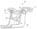
図1に典型的な車両ドアヒンジ10を示す。ドアヒンジ10は第1のヒンジ部分11および第2のヒンジ部分12を含み、この第2のヒンジ部分はヒンジ軸19まわりで第1のヒンジ部分11と旋回式に接続される。ヒンジピン15はヒンジ軸19を通過し、第1のヒンジ部分11と第2のヒンジ部分12とを互いに接続する。第1のヒンジ部分は中心領域に孔17を含むことがあり、これは図4,5に示す装置30など、この発明に従う取外し可能ドアチェック装置の接触要素と係合するために用いられ得る。車両ヒンジによっては、ヒンジ10の一方の側から他方の側へ渡る単一のヒンジピン15の代わりに、このヒンジにおける各々の側にピンが1つづつある分割ピンが使用される(たとえば図5のヒンジ100を参照)。他の車両ヒンジ、たとえば図7に示すヒンジ200では、第1および第2のヒンジ部分のうち1つが、このヒンジピンを取囲むスリーブ部分を含み得る。
DETAILED DESCRIPTION A typical
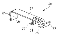
この発明に従う取外し可能ドアチェック装置の第1の実施例20を図2,3に示す。取外し可能ドアチェック装置20は本体21を含む。本体21の一端では、第1の接触要素22が下方に延びて第1の接触表面24を含み、これは第1のヒンジ部分11の後方端縁14と係合するように構成される(図1,3に示す)。クリップ要素26が本体21の中間部分から下方に延び、第1のヒンジ部分11の前方端縁13と係合するように構成される(図3に示す)。屈曲端部27がヒンジ部分21の下側の面まわりに延び、ドアチェック装置20をヒンジ部分11に固く保持する。本体21の、第1の接触要素22と反対の端部からは、第2の接触要素23が延びている。第2の接触要素23は、本体21から下方に延びてから再び上方に曲がっており、第2のヒンジ部分12の前方端縁16と係合するように構成された接触表面25を含む。
A
取外し可能ドアチェック装置20は、単一の金属ストリップなど単一の可撓性材料片から完全に形成されることが好ましい。第1および第2の接触要素およびクリップ要素は、打抜きによって形成できる。これに代えてドアチェック装置20は、弾性の熱可塑性材料を用いて成形され得る。
The removable
図3では、ヒンジ100に取付けられたドアチェック装置20を、ヒンジ部分10の開
いた位置について示す。この位置付けでは、ドアチェック装置20は第1のヒンジ部分11に固く取付けられる。第1のヒンジ部分11への取付を行なうには、車両ドアを部分的に開いた位置に動かして、ヒンジに接近できるようにすればよい。クリップ要素26を第1のヒンジ部分11の前方端縁13に引っ掛け、それから第1の接触要素22をヒンジ部分11の後方端縁14にパチンと留める。ドアチェック装置20の形状、および材料の可撓性という性質のため、第1の接触部材22とクリップ要素26との相対的な位置を引き伸ばすことが可能であり、こうして、第1の接触部材を後方端縁14と嵌合させてから正しい位置にパチンと留め、第1の接触表面24を後方端縁14と係合させることができる。取外し可能ドアチェック装置の設置は、ヒンジの組立中または車両への設置前でもよい。
In FIG. 3, the
次に、車両ドアを完全に開いた位置へと動かすと、第2のヒンジ部分12はドアチェック装置20の第2の接触要素23と接触する。やはりドアチェック装置20の材料の可撓性という性質および第2の接触要素23のカーブした形状のため、第2のヒンジ部分12は第2の接触要素23と接触してこれを上方へ変位させる。第2のヒンジ部分12がその開いた位置へと進むのに伴い、第2のヒンジ部分12は下方へと戻り、こうして第2の接触表面25は第2のヒンジ部分12の前方端縁16と係合する。こうして装置20は、一方では接触要素22の第1の接触表面24と、他方では第2の要素23の第2の接触表面25との間で、ヒンジ10を開いた位置に保持する。
Next, when the vehicle door is moved to the fully open position, the
装置20はヒンジ部分11,12を互いに対して、解放可能な態様で保持する。ヒンジ10上にかかる外部からの閉める力(たとえば閉じる方向に車両ドアを押すことによるもの)は、第1の接触要素22と第2の接触要素23との間に張力を生じさせる。装置20の形状およびその材料の可撓性という性質のため、閉める力が十分に強ければ、第2の接触要素23は、第1の接触要素22に対して、第2のヒンジ部分12を解放するのに十分に反らされ、こうしてヒンジ10は再びその閉じた位置へと自由に動くことができる。
The
ドアが部分的に開いた位置にあるときに後方端縁14上で第1の接触要素22を持上げることにより、ドアチェック装置20を再び第1のヒンジ部分11から容易に取外すことができる。
By lifting the
ドアチェック装置20の形状は、第1の接触表面24および第2の接触表面25が互いの方を向くようなものにされる。ここでの「互いの方を向く」とは、表面が必ず直接互いの方を向いていることや、あるいは表面が同一平面上にあったり互いに平行であったりすることを意味しない。むしろ、一方の表面についての面が、他方の表面についての面の方向と90°未満の方向を指せば十分である。
The shape of the
図4,5に取外し可能ドアチェック装置の第2の実施例30を示す。第2の実施例では、ドアチェック装置30は、円筒形ピンの形をとって本体31から下方に延びる第1の要素32を含み、この円筒形ピンは第1のヒンジ部分11内の孔17と係合するように構成される。孔17は、図5ではドアチェック装置30の本体31で遮られていて見ることができないが、図1に示すヒンジ10では見ることができる。図6は、ドアチェック装置の第3の実施例であって、ヒンジピン15を有するヒンジで使用されているものを示す。第3の実施例と第2の実施例との相違は装置の本体31の形状のみである。これら実施例は類似しているので、図5に示す第2の実施例および図6に示す第3の実施例の両方で対応する特徴点については、同じ参照番号を用いて示す。
4 and 5 show a
ドアチェック装置30は単一の材料片から完全に形成されることが好ましく、これにはたとえば弾性の熱可塑性材料から成形されたものがある。円筒形ピン32は外側フランジ41を含み、これは孔17の遠端と係合するように構成され、これによりドアチェック装
置30を第1のヒンジ部分11に固く取付けて保持する。第1の接触表面34は、ピン32の外側表面のうち、フランジ41と本体31との間の部分を含み、第1のヒンジ部分11の孔17の内側表面と係合する。ピン32の端部42はフランジ41(および孔17)よりも小さい直径を有し、円錐形状で先細りにされており、直径はフランジ41の直径になるまで徐々に増加する。端部42の直径が小さくなり徐々に先細りしているので、接触要素32を孔17に挿入することが容易となる。
The
ドアチェック装置30はまた、本体31から延びる第1の可撓性アーム38および第2の可撓性アーム39の形をとる第2の接触要素33を含む。車両ドアを開いた位置に動かすのに伴い、ヒンジ部分12の側壁は、第1のアーム38の端部44と第2のアーム39の端部45とを互いの方へと強制する。端部44,45が互いの方に強制されるのに伴い、第2の接触表面40および第3の接触表面45は第1の要素23の第1の接触表面34に対して変位される。第1のアーム38の第2の接触表面35および第2のアーム39の第3の接触表面40は、開いた位置においてヒンジ部分12の前方端縁16と係合し、こうしてヒンジ100(およびこれに従い車両ドア)を解放可能に開いた位置で保持する。
The
第2の接触表面40および第3の接触表面35は第1の接触表面34の方を向き、これは第1のヒンジ部分11の孔17の内側表面と係合する。ヒンジ100の閉じる方向での外部からの力は第1の接触要素32と第2の接触要素33との間に張力を働かせる。外部からの閉める力が十分に大きければ、可撓性アーム38,39の端部44,45は、第2のヒンジ部分12の側壁によって互いの方へ変位され、ヒンジは開いた位置から解放される。
The
本体31をヒンジ部分11から引離すことでピン32を孔17から外せば、ドアチェック装置30を第1のヒンジ部分11から容易に取外すことができる。装置30の材料の可撓性という性質のため、それほど大きくない力でフランジ41を孔17の遠端から解放することができる。
If the
図8は、図7では閉じた位置で示したドアヒンジ200と同様のドアヒンジとともに使用される取外し可能ドアチェック装置の第4の実施例50を示す。ドアチェック装置50は、円筒形ピンの形をとって本体51から下方に延びる第1の要素52を含み、これはヒンジ200の第1のヒンジ部分11内の孔18と係合するように構成される。図4,5に示すドアチェック装置30と同様に、ドアチェック装置50は好ましくは単一の材料片から完全に形成され、これにはたとえば弾性の熱可塑性材料から成形されたものがある。円筒形ピン52は外側フランジ61を含み、これは孔18の遠端と係合するように構成され、こうしてドアチェック装置50をヒンジ200の第1のヒンジ部分11に固く取付けて保持する。第1の接触表面54は、ピン52の外側表面のうち、フランジ61と本体51との間の部分を含み、第1のヒンジ部分11の孔18の内側表面と係合する。ピン52の端部61はフランジ61(および孔18)よりも小さい直径を有し、円錐形状で先細りにされており、直径はフランジ61の直径になるまで徐々に増加する。端部62の直径が小さくなり徐々に先細りしているので、接触要素52を孔18に挿入することが容易となる。ドアチェック装置50は、アーム58,59が第2のヒンジ部分12の方向を指すように第1のヒンジ部分11に置かれる。
FIG. 8 shows a
ドアチェック装置50はまた、本体51から延びる第1の可撓性アーム58および第2の可撓性アーム59の形をとる第2の接触要素53を含む。車両ドアを開いた位置へ動かすと、第1のヒンジ部分11およびドアチェック装置50は第2のヒンジ部分12の傾斜面の方に動く。第1のアーム58の端部64および第2のアーム59の端部65は、第2のヒンジ部分12の傾斜面によって、互いから離れるように強制される。端部64,65が互いから離れるように強制されると、第2の接触表面60および第3の接触表面55は
第1の要素52の第1の接触表面54に対して変位される。第1のアーム58の第2の接触表面55および第2のアーム59の第3の接触表面60は、開いた位置においてヒンジ部分12の三角形の開口部の内側端縁部分と係合することにより、ヒンジ200(およびこれに従い車両ドア)を解放可能に開いた位置で保持する。
The
当然のことながら、以上におけるこの発明の記載は単に例示であり、この発明の範囲内でその詳細は変更可能であることが理解されるであろう。 Of course, it will be understood that the above description of the invention is exemplary only, and details thereof may be varied within the scope of the invention.
10 車両ドアヒンジ、11 第1のヒンジ部分、12 第2のヒンジ部分、14 第1のヒンジ部分の後方端縁、15 ヒンジピン、17 孔、19 ヒンジ軸、20 第1の実施例の取外し可能ドアチェック装置、21 本体、22 第1の接触要素、23 第2の接触要素、24 第1の接触表面、25 接触表面、26 クリップ要素、27 屈曲端部、30 第2の実施例のドアチェック装置、31 本体、32 ピン状の第1の接触要素、33 第2の接触要素、34 第1の接触表面、35 第2の接触表面、38 第1の可撓性アーム、39 第2の可撓性アーム、40 第2の接触表面、41 外側フランジ、42 ピンの端部、44 第1のアームの端部、45 第2のアームの端部、50 第4の実施例のドアチェック装置、51 本体、52 第1の要素、53 第2の接触要素、54 接触表面、55 第2の接触要素、58 第1のアーム、59 第2のアーム、60 第2の接触表面、61 フランジ、64 第1のアームの端部、65 第2のアームの端部、100 ヒンジ、200 ヒンジ。
DESCRIPTION OF
Claims (16)
本体(21)と、
前記本体(21)から延び、第1の接触表面(24)を有する第1の接触要素(22)と、
前記本体(21)から延び、第2の接触表面(25)を有する第2の接触要素(23)とを備え、
前記装置はさらに前記本体(21)から延びるクリップ要素(26)を含み、前記クリップ要素(26)のうちの1つおよび第1の接触要素(22)は可撓性弾性材料でできており、前記クリップ要素(26)および前記第1の接触表面(24)は前記第1のヒンジ部分(11)を握持し、さらに、
第2の接触要素(23)の第2の接触表面(25)は、前記ドアヒンジ(10)の前記開いた位置において、前記第2のヒンジ部分(12)と接触するようになることを特徴とする、取外し可能ドアチェック装置。 Removable door check device for use with a door hinge (10) , wherein the door check device comprises a first hinge portion (11) and a second hinge portion (12) in an open position of the door hinge (10). Holding the device
A body (21) ;
A first contact element (22) extending from the body (21) and having a first contact surface (24) ;
A second contact element (23) extending from the body (21) and having a second contact surface (25) ;
The apparatus further includes a clip element (26) extending from the body (21), wherein one of the clip elements (26) and the first contact element (22) are made of a flexible elastic material; The clip element (26) and the first contact surface (24) grip the first hinge portion (11);
The second contact surface (25) of the second contact element (23) comes into contact with the second hinge part (12) in the open position of the door hinge (10). A removable door check device.
は反対の端部から下方に延びることを特徴とする、請求項1から4のいずれかに記載の取外し可能ドアチェック装置。 The second contact element (23) is connected to the first contact element (22) of the body (21).
5. A removable door check device according to any of claims 1 to 4, characterized in that extends downward from the opposite end .
第1の接触要素(32;52)と第1の接触表面(34;54)と第2の接触要素(33;53)とを有する本体(31;51)を含み、前記第1の接触要素(32;52)および前記第2の接触要素(33;53)は前記本体(31;51)から延び、
前記第2の接触要素(33;53)は、第2の接触表面(35;55)を有する第1のアーム(38;58)と、第3の接触表面(40;60)を有する第2のアーム(39;59)とを含み、前記ドアヒンジ(10)の前記開いた位置において前記第2の接触表面(35;55)および前記第3の接触表面(40;60)は前記第2のヒンジ部分(12)と係合し、
前記第1のアーム(38;58)は前記第2のアーム(39;59)に対して可撓的に変位可能であることを特徴とする、取外し可能ドアチェック装置。 Removable door check device for use with a door hinge (10), wherein the door check device comprises a first hinge portion (11) and a second hinge portion (12) in an open position of the door hinge (10). Holding the device
A body (31; 51) having a first contact element (32; 52), a first contact surface (34; 54) and a second contact element (33; 53), said first contact element (32; 52) and the second contact element (33; 53) extend from the body (31; 51);
The second contact element (33; 53) comprises a first arm (38; 58) having a second contact surface (35; 55) and a second having a third contact surface (40; 60). And the second contact surface (35; 55) and the third contact surface (40; 60) in the open position of the door hinge (10) are the second contact surface (40; 60). Engaging the hinge part (12),
Removable door check device, characterized in that the first arm ( 38 ; 58 ) is flexibly displaceable with respect to the second arm (39; 59).
第1のヒンジ部分(11)と、 A first hinge portion (11);
前記第1のヒンジ部分に旋回式に接続された第2のヒンジ部分(12)と、 A second hinge portion (12) pivotally connected to the first hinge portion;
前記ドアヒンジ(10)が開いた位置において前記第1のヒンジ部分(11)および前 The first hinge part (11) and the front in the position where the door hinge (10) is open
記第2のヒンジ部分(12)を保持するよう構成される取外し可能ドアチェック装置とを備え、A removable door check device configured to hold the second hinge portion (12);
前記ドアチェック装置は、請求項1から9のいずれかに従って構成されることを特徴とする、ドアヒンジ。 The door check device is configured according to any one of claims 1 to 9, and is a door hinge.
第1のヒンジ部分(11)と、 A first hinge portion (11);
前記第1のヒンジ部分に旋回式に接続された第2のヒンジ部分(12)と、 A second hinge portion (12) pivotally connected to the first hinge portion;
前記ドアヒンジ(10)が開いた位置において前記第1のヒンジ部分(11)および前記第2のヒンジ部分(12)を保持するよう構成される取外し可能ドアチェック装置とを備え、 A removable door check device configured to hold the first hinge portion (11) and the second hinge portion (12) in an open position of the door hinge (10);
前記ドアチェック装置は、請求項10から14のいずれかに従って構成されることを特徴とする、ドアヒンジ。 The door check device is configured according to any one of claims 10 to 14, and is a door hinge.
Applications Claiming Priority (1)
| Application Number | Priority Date | Filing Date | Title |
|---|---|---|---|
| US10/358,459 US6948214B2 (en) | 2003-02-05 | 2003-02-05 | Removable door check device |
Publications (3)
| Publication Number | Publication Date |
|---|---|
| JP2004239059A JP2004239059A (en) | 2004-08-26 |
| JP2004239059A5 JP2004239059A5 (en) | 2007-03-01 |
| JP4557561B2 true JP4557561B2 (en) | 2010-10-06 |
Family
ID=32771194
Family Applications (1)
| Application Number | Title | Priority Date | Filing Date |
|---|---|---|---|
| JP2004029603A Expired - Lifetime JP4557561B2 (en) | 2003-02-05 | 2004-02-05 | Door hinge and removable door check device |
Country Status (3)
| Country | Link |
|---|---|
| US (1) | US6948214B2 (en) |
| JP (1) | JP4557561B2 (en) |
| DE (1) | DE102004005864B4 (en) |
Families Citing this family (20)
| Publication number | Priority date | Publication date | Assignee | Title |
|---|---|---|---|---|
| KR20040013002A (en) * | 2001-06-29 | 2004-02-11 | 프로-테크 베라퉁스-운트 엔트비크룽스 게엠베하 | Fixture for holding a vehicle body part |
| WO2007024832A1 (en) * | 2005-08-22 | 2007-03-01 | E. I. Du Pont De Nemours And Company | Improved metallic hinge motion check friction device including a one-piece design, methods incorporating the device, and uses thereof |
| FR2892140B1 (en) * | 2005-10-17 | 2008-01-11 | Exsto Soc Par Actions Simplifi | DEVICE FOR INTERIOR CLEARING AND INTERLOCKING OF AN ELEMENT OPENING ON A FIXED ELEMENT |
| US7559114B2 (en) | 2006-05-11 | 2009-07-14 | Anthony Ranilovich | Hinge attachable door stop insert |
| GB2440340B (en) * | 2006-07-27 | 2011-11-09 | Ford Global Tech Llc | Vehicle painting accessory |
| US20080036348A1 (en) * | 2006-08-09 | 2008-02-14 | Maytag Corp. | Brace for a refrigerator machine compartment cover |
| US8127401B2 (en) * | 2009-10-08 | 2012-03-06 | Ford Global Technologies, Llc | Method and removable clip for holding a vehicle door open |
| RU2493346C2 (en) * | 2010-11-08 | 2013-09-20 | Закрытое Акционерное Общество "Полад" | Nondetachable double-link door hinge of car |
| US8869451B2 (en) * | 2011-07-19 | 2014-10-28 | Rhoost, LLC | Finger guard safety device |
| US8869350B2 (en) * | 2011-09-06 | 2014-10-28 | Multimatic Inc. | Torsion bar door check |
| US20130055529A1 (en) * | 2011-09-06 | 2013-03-07 | Rudolf Gruber | Torsion Bar Door Check |
| US20130113353A1 (en) * | 2011-11-03 | 2013-05-09 | Bsh Home Appliances Corporation | Household appliance including snap-on toe kick panel |
| US8556330B2 (en) | 2012-01-13 | 2013-10-15 | Chrysler Group Llc | Removable door with hinge detent |
| CN107303801A (en) * | 2016-04-21 | 2017-10-31 | 福特环球技术公司 | The door system for providing audit function in vehicle and assisting door to close and open |
| DE102019109553B3 (en) | 2019-04-11 | 2020-06-18 | Dr. Ing. H.C. F. Porsche Aktiengesellschaft | hinge |
| US11970892B2 (en) * | 2021-05-20 | 2024-04-30 | Summit Products, Inc. | Door stop system |
| US11613170B2 (en) | 2021-08-26 | 2023-03-28 | Fca Us Llc | Stowable check strap assembly for vehicle door |
| US11725435B2 (en) * | 2021-10-01 | 2023-08-15 | Michael A Papoulias | Door hinge limiter for automotive vehicle |
| US11629535B2 (en) * | 2021-10-02 | 2023-04-18 | William Steven Kroll | Surface mounted door check device |
| US20240328218A1 (en) * | 2023-03-31 | 2024-10-03 | Benito Moreno | Automotive Vehicle Door Restraint System |
Citations (1)
| Publication number | Priority date | Publication date | Assignee | Title |
|---|---|---|---|---|
| JPH0510121Y2 (en) * | 1988-03-16 | 1993-03-12 |
Family Cites Families (20)
| Publication number | Priority date | Publication date | Assignee | Title |
|---|---|---|---|---|
| US3729772A (en) * | 1972-03-13 | 1973-05-01 | Atwood Vacuum Machine Co | Torsion bar hold-open hinge |
| DE7735479U1 (en) * | 1977-11-19 | 1978-03-09 | Fa. Richard Heinze, 4900 Herford | HINGES, IN PARTICULAR FOR FURNITURE |
| US4858273A (en) * | 1983-09-15 | 1989-08-22 | Gennaro Civitelli | Door stop having multiple mounting positions |
| US5450652A (en) * | 1993-03-18 | 1995-09-19 | Webb; Walter E. | Hinge mounted door chock |
| EP0653536B1 (en) * | 1993-11-13 | 1999-01-20 | Upf Group Plc | Hinge Assembly |
| US5577295A (en) | 1994-09-27 | 1996-11-26 | Chrysler Corporation | Three diameter hinge pin |
| US5675865A (en) * | 1996-04-17 | 1997-10-14 | Van Der Steur; Gunnar | Door stop |
| US5692264A (en) * | 1996-04-17 | 1997-12-02 | Van Der Steur; Gunnar | Door stop |
| US6003911A (en) * | 1996-05-31 | 1999-12-21 | Sowash; Michael Robert C. | Door stop |
| DE19652625A1 (en) * | 1996-11-30 | 1998-06-04 | Scharwaechter Gmbh Co Kg | Removable door hinge for motor vehicle doors |
| US5711557A (en) * | 1996-12-12 | 1998-01-27 | Nicolosi; Louis | Door stop |
| US5924170A (en) * | 1997-09-05 | 1999-07-20 | Chrysler Corporation | Vehicle door hinge with removable detent mechanism |
| US6016588A (en) * | 1998-07-17 | 2000-01-25 | Kamerschen; Keith C. | Combination door catch and stop |
| US6108866A (en) | 1998-10-29 | 2000-08-29 | Chrysler Corporation | Detent mechanism for a vehicle door |
| US6332243B1 (en) * | 1998-12-21 | 2001-12-25 | Multimatic Inc. | Vehicle door prop button |
| DE69908560T2 (en) * | 1998-12-21 | 2004-05-06 | Multimatic Inc., Markham | MOTOR VEHICLE DOOR STOP CLAMP FOR A MOTOR VEHICLE HINGE WITH SPLIT PINS |
| DE19932443C2 (en) * | 1999-06-25 | 2001-04-26 | Lina Gronbach | hinge |
| US6430835B1 (en) | 2000-04-28 | 2002-08-13 | Daimlerchrysler Corporation | Setting fixture for door measurement |
| JP2002250169A (en) * | 2001-02-26 | 2002-09-06 | Zenji Tsuchikawa | Turn regulator for blade plate of hinge |
| DE10156300B4 (en) * | 2001-11-19 | 2006-07-27 | Edscha Ag | hinge |
-
2003
- 2003-02-05 US US10/358,459 patent/US6948214B2/en not_active Expired - Fee Related
-
2004
- 2004-02-05 JP JP2004029603A patent/JP4557561B2/en not_active Expired - Lifetime
- 2004-02-05 DE DE102004005864A patent/DE102004005864B4/en not_active Expired - Lifetime
Patent Citations (1)
| Publication number | Priority date | Publication date | Assignee | Title |
|---|---|---|---|---|
| JPH0510121Y2 (en) * | 1988-03-16 | 1993-03-12 |
Also Published As
| Publication number | Publication date |
|---|---|
| DE102004005864A1 (en) | 2004-09-09 |
| JP2004239059A (en) | 2004-08-26 |
| US20040148735A1 (en) | 2004-08-05 |
| DE102004005864B4 (en) | 2008-09-18 |
| US6948214B2 (en) | 2005-09-27 |
Similar Documents
| Publication | Publication Date | Title |
|---|---|---|
| JP4557561B2 (en) | Door hinge and removable door check device | |
| KR100449314B1 (en) | Plastic clamp | |
| KR100938320B1 (en) | Tape measure mounting clip | |
| US10935179B2 (en) | Wire pressing and holding device for an extension arm support mechanism | |
| KR101807443B1 (en) | Turning structure | |
| JP3607154B2 (en) | The head cover of the arm head that composes the wiper arm | |
| JP4557560B2 (en) | Door hinge and removable door check device | |
| JPH10148052A (en) | Attaching/detaching structure of cover | |
| JP4784837B2 (en) | Sealed mounting structure for parts | |
| JPH10274222A (en) | Shaft body operating handle | |
| JP4738650B2 (en) | Vehicle door handle device | |
| JP4113719B2 (en) | Noise current absorber | |
| JP2001080469A (en) | Wiper structure | |
| JP3601306B2 (en) | Clamp fixing structure of wire harness protector | |
| JP2001001758A (en) | Retention structure for vehicle sun visor | |
| KR200270241Y1 (en) | Tape application jig for vehicle door sash | |
| JP3827884B2 (en) | Lever handle for door | |
| KR100449969B1 (en) | Vehicle door prop button | |
| JP3274666B2 (en) | Hinge for doors that accept tightening operation | |
| JPS61156582A (en) | Tape cartridge | |
| JP2008006884A (en) | Assist grip | |
| FR2815681A1 (en) | Fastener, for attaching molding with studs to car door with mounting holes, comprises pin which fits through hole and has head into which stud fits, nut with slot on one side fitting into second slot in head, so that arms fit around stud | |
| JP4887534B2 (en) | Instrument panel for forklift | |
| JP2002048119A (en) | Split pin for amusement machine | |
| JP2575000B2 (en) | Umbrella bone joint of Western umbrella |
Legal Events
| Date | Code | Title | Description |
|---|---|---|---|
| A521 | Request for written amendment filed |
Free format text: JAPANESE INTERMEDIATE CODE: A523 Effective date: 20070111 |
|
| A621 | Written request for application examination |
Free format text: JAPANESE INTERMEDIATE CODE: A621 Effective date: 20070111 |
|
| A131 | Notification of reasons for refusal |
Free format text: JAPANESE INTERMEDIATE CODE: A131 Effective date: 20091215 |
|
| A601 | Written request for extension of time |
Free format text: JAPANESE INTERMEDIATE CODE: A601 Effective date: 20100312 |
|
| A602 | Written permission of extension of time |
Free format text: JAPANESE INTERMEDIATE CODE: A602 Effective date: 20100317 |
|
| A521 | Request for written amendment filed |
Free format text: JAPANESE INTERMEDIATE CODE: A523 Effective date: 20100331 |
|
| TRDD | Decision of grant or rejection written | ||
| A01 | Written decision to grant a patent or to grant a registration (utility model) |
Free format text: JAPANESE INTERMEDIATE CODE: A01 Effective date: 20100622 |
|
| A01 | Written decision to grant a patent or to grant a registration (utility model) |
Free format text: JAPANESE INTERMEDIATE CODE: A01 |
|
| A61 | First payment of annual fees (during grant procedure) |
Free format text: JAPANESE INTERMEDIATE CODE: A61 Effective date: 20100720 |
|
| R150 | Certificate of patent or registration of utility model |
Ref document number: 4557561 Country of ref document: JP Free format text: JAPANESE INTERMEDIATE CODE: R150 Free format text: JAPANESE INTERMEDIATE CODE: R150 |
|
| FPAY | Renewal fee payment (event date is renewal date of database) |
Free format text: PAYMENT UNTIL: 20130730 Year of fee payment: 3 |
|
| R250 | Receipt of annual fees |
Free format text: JAPANESE INTERMEDIATE CODE: R250 |
|
| R250 | Receipt of annual fees |
Free format text: JAPANESE INTERMEDIATE CODE: R250 |
|
| R250 | Receipt of annual fees |
Free format text: JAPANESE INTERMEDIATE CODE: R250 |
|
| R250 | Receipt of annual fees |
Free format text: JAPANESE INTERMEDIATE CODE: R250 |
|
| R250 | Receipt of annual fees |
Free format text: JAPANESE INTERMEDIATE CODE: R250 |
|
| R250 | Receipt of annual fees |
Free format text: JAPANESE INTERMEDIATE CODE: R250 |
|
| R250 | Receipt of annual fees |
Free format text: JAPANESE INTERMEDIATE CODE: R250 |
|
| R250 | Receipt of annual fees |
Free format text: JAPANESE INTERMEDIATE CODE: R250 |
|
| R250 | Receipt of annual fees |
Free format text: JAPANESE INTERMEDIATE CODE: R250 |
|
| R250 | Receipt of annual fees |
Free format text: JAPANESE INTERMEDIATE CODE: R250 |
|
| R250 | Receipt of annual fees |
Free format text: JAPANESE INTERMEDIATE CODE: R250 |
|
| EXPY | Cancellation because of completion of term |