JP4557032B2 - Recording device - Google Patents
Recording device Download PDFInfo
- Publication number
- JP4557032B2 JP4557032B2 JP2008090043A JP2008090043A JP4557032B2 JP 4557032 B2 JP4557032 B2 JP 4557032B2 JP 2008090043 A JP2008090043 A JP 2008090043A JP 2008090043 A JP2008090043 A JP 2008090043A JP 4557032 B2 JP4557032 B2 JP 4557032B2
- Authority
- JP
- Japan
- Prior art keywords
- ink
- unit
- liquid
- channel
- port
- Prior art date
- Legal status (The legal status is an assumption and is not a legal conclusion. Google has not performed a legal analysis and makes no representation as to the accuracy of the status listed.)
- Active
Links
- 239000007788 liquid Substances 0.000 claims description 38
- 230000007246 mechanism Effects 0.000 claims description 29
- 238000004891 communication Methods 0.000 claims description 16
- 239000013013 elastic material Substances 0.000 claims description 3
- 239000000976 ink Substances 0.000 description 258
- 238000010926 purge Methods 0.000 description 58
- 238000012423 maintenance Methods 0.000 description 38
- 239000002699 waste material Substances 0.000 description 13
- 238000007599 discharging Methods 0.000 description 12
- 239000000428 dust Substances 0.000 description 10
- 238000011144 upstream manufacturing Methods 0.000 description 9
- 238000010586 diagram Methods 0.000 description 6
- 230000002093 peripheral effect Effects 0.000 description 6
- 238000000034 method Methods 0.000 description 5
- 239000012535 impurity Substances 0.000 description 4
- 230000004048 modification Effects 0.000 description 4
- 238000012986 modification Methods 0.000 description 4
- 239000011159 matrix material Substances 0.000 description 2
- 239000011347 resin Substances 0.000 description 2
- 229920005989 resin Polymers 0.000 description 2
- 230000007723 transport mechanism Effects 0.000 description 2
- XUIMIQQOPSSXEZ-UHFFFAOYSA-N Silicon Chemical compound [Si] XUIMIQQOPSSXEZ-UHFFFAOYSA-N 0.000 description 1
- 239000000853 adhesive Substances 0.000 description 1
- 230000001070 adhesive effect Effects 0.000 description 1
- 239000003086 colorant Substances 0.000 description 1
- 230000003028 elevating effect Effects 0.000 description 1
- 238000010030 laminating Methods 0.000 description 1
- 239000007769 metal material Substances 0.000 description 1
- 229910052710 silicon Inorganic materials 0.000 description 1
- 239000010703 silicon Substances 0.000 description 1
- 229910001220 stainless steel Inorganic materials 0.000 description 1
- 239000010935 stainless steel Substances 0.000 description 1
- XLYOFNOQVPJJNP-UHFFFAOYSA-N water Substances O XLYOFNOQVPJJNP-UHFFFAOYSA-N 0.000 description 1
Images


Classifications
-
- B—PERFORMING OPERATIONS; TRANSPORTING
- B41—PRINTING; LINING MACHINES; TYPEWRITERS; STAMPS
- B41J—TYPEWRITERS; SELECTIVE PRINTING MECHANISMS, i.e. MECHANISMS PRINTING OTHERWISE THAN FROM A FORME; CORRECTION OF TYPOGRAPHICAL ERRORS
- B41J2/00—Typewriters or selective printing mechanisms characterised by the printing or marking process for which they are designed
- B41J2/005—Typewriters or selective printing mechanisms characterised by the printing or marking process for which they are designed characterised by bringing liquid or particles selectively into contact with a printing material
- B41J2/01—Ink jet
- B41J2/135—Nozzles
- B41J2/165—Prevention or detection of nozzle clogging, e.g. cleaning, capping or moistening for nozzles
- B41J2/16585—Prevention or detection of nozzle clogging, e.g. cleaning, capping or moistening for nozzles for paper-width or non-reciprocating print heads
-
- B—PERFORMING OPERATIONS; TRANSPORTING
- B41—PRINTING; LINING MACHINES; TYPEWRITERS; STAMPS
- B41J—TYPEWRITERS; SELECTIVE PRINTING MECHANISMS, i.e. MECHANISMS PRINTING OTHERWISE THAN FROM A FORME; CORRECTION OF TYPOGRAPHICAL ERRORS
- B41J2/00—Typewriters or selective printing mechanisms characterised by the printing or marking process for which they are designed
- B41J2/005—Typewriters or selective printing mechanisms characterised by the printing or marking process for which they are designed characterised by bringing liquid or particles selectively into contact with a printing material
- B41J2/01—Ink jet
- B41J2/135—Nozzles
- B41J2/165—Prevention or detection of nozzle clogging, e.g. cleaning, capping or moistening for nozzles
- B41J2/16517—Cleaning of print head nozzles
- B41J2/16535—Cleaning of print head nozzles using wiping constructions
- B41J2/16544—Constructions for the positioning of wipers
Landscapes
- Ink Jet (AREA)
Description
本発明は、液滴を吐出して記録媒体に画像を記録する記録装置に関する。 The present invention relates to a recording apparatus that records an image on a recording medium by discharging droplets.
インクジェットプリンタのインクジェットヘッドとしては、インクが供給される供給口と連通する共通インク室と、共通インク室の出口から圧力室を介してインク吐出面に開口するノズルに至る複数の個別インク流路とを有しており、各圧力室内のインクにパルス状の圧力を付与することによってノズルからインク滴を吐出するものがある。このインクジェットヘッド内に形成された流路内に気泡やゴミが混入すると、圧力室においてインクに付与された圧力波が正常に伝播しなくなり、インク吐出特性が低下することがある。そこで、供給口からインクを強制的に供給することによって、流路内に混入した気泡やゴミをインクと共にノズルから強制排出し、その後、インク吐出面をワイプ部材で払拭することによってインク吐出面に残存するインクを除去する技術が知られている(特許文献1参照)。 The inkjet head of the inkjet printer includes a common ink chamber that communicates with a supply port to which ink is supplied, and a plurality of individual ink flow paths that extend from the outlet of the common ink chamber to nozzles that open to the ink ejection surface via the pressure chamber. And ejecting ink droplets from nozzles by applying a pulsed pressure to ink in each pressure chamber. If bubbles or dust are mixed in the flow path formed in the ink jet head, the pressure wave applied to the ink in the pressure chamber may not propagate normally, and the ink ejection characteristics may be deteriorated. Therefore, by forcibly supplying ink from the supply port, bubbles and dust mixed in the flow path are forcibly discharged from the nozzle together with the ink, and then the ink discharge surface is wiped with a wipe member to the ink discharge surface. A technique for removing the remaining ink is known (see Patent Document 1).
上述した技術によると、インク吐出面の長手方向に沿ってワイプ部材を移動させることによって、インク吐出面を払拭する。ノズル内においては、水頭圧によって負圧が発生しており、ノズルからインクが排出されてからワイプ部材によるインク吐出面の払拭が完了するまでの間、インク吐出面に残存するインクが、時間の経過に伴ってノズル内に吸引される。このため、インクと共に排出された気泡やゴミがノズルの開口近辺に存在していると、この気泡やゴミがインク吐出面に残存するインクと共に再びノズル内に吸引されることがある。そこで、排出された気泡やゴミがノズル内に吸引されないように、排出された気泡やゴミがノズルの開口から十分に離れるように多量のインクを排出しなければならず、インクが無駄に消費されてしまう。 According to the above-described technique, the ink discharge surface is wiped by moving the wipe member along the longitudinal direction of the ink discharge surface. In the nozzle, a negative pressure is generated due to the water head pressure, and the ink remaining on the ink ejection surface from the time the ink is discharged from the nozzle until the wiping of the ink ejection surface by the wipe member is completed As it progresses, it is sucked into the nozzle. For this reason, if bubbles and dust discharged together with the ink exist in the vicinity of the nozzle opening, the bubbles and dust may be sucked into the nozzle again together with the ink remaining on the ink discharge surface. Therefore, in order to prevent the discharged bubbles and dust from being sucked into the nozzle, a large amount of ink must be discharged so that the discharged bubbles and dust are sufficiently separated from the nozzle opening, and the ink is wasted. End up.
そこで、本発明は、液滴吐出ヘッドから気泡やゴミを排出するときに、吐出口から排出される液体の量を少なくすることができる記録装置を提供することを目的とする。 SUMMARY An advantage of some aspects of the invention is that it provides a recording apparatus capable of reducing the amount of liquid discharged from a discharge port when bubbles and dust are discharged from a droplet discharge head.
本発明の記録装置は、液体が流入する流入口を有する複数の流入流路と、互いに異なる前記流入流路と連通する複数の共通液体流路と、前記共通液体流路の出口から圧力室を介して吐出面に開口する吐出口に至る複数の個別液体流路とを有し、一方向に延在した液滴吐出ヘッドと、前記複数の流入流路のいずれかに選択的に液体を供給する供給手段と、弾性材料からなるワイプ部材と、前記ワイプ部材が前記吐出面と接触した状態で、前記ワイプ部材を前記一方向に移動させる移動機構と、前記供給手段及び前記移動機構を制御する制御手段とを備えている。前記吐出面において、同一の前記流入流路に連通する前記吐出口がそれぞれ配置された複数の分割領域が、前記一方向に関して配列されており、前記制御手段は、前記分割領域に配置された前記吐出口から所定量の液体が排出されるまで、各分割領域に対応する前記流入流路に液体を前記配列の順に供給するように、前記供給手段を制御すると共に、前記吐出口から所定量の液体が排出された順に各分割領域を前記ワイプ部材によって払拭するように、前記移動機構を制御し、且つ、前記ワイプ部材が前記分割領域を払拭し始める直前に、当該分割領域の吐出口から前記所定量の液体が排出し終わるように、前記供給手段及び前記移動機構を制御する。
The recording apparatus of the present invention includes a plurality of inflow channels having an inflow port through which liquid flows, a plurality of common liquid channels communicating with the different inflow channels, and a pressure chamber from an outlet of the common liquid channel. A plurality of individual liquid passages that reach the ejection openings that open to the ejection surface, and selectively supply liquid to one of the plurality of inflow passages and a liquid droplet ejection head that extends in one direction. Supply means, a wipe member made of an elastic material, a moving mechanism for moving the wipe member in the one direction in a state where the wipe member is in contact with the discharge surface, and controlling the supply means and the moving mechanism. Control means. On the discharge surface, a plurality of divided regions each having the discharge port communicating with the same inflow channel are arranged in the one direction, and the control means is arranged in the divided region. Until the predetermined amount of liquid is discharged from the discharge port, the supply means is controlled so that the liquid is supplied in the order of the arrangement to the inflow channel corresponding to each divided region, and the predetermined amount of liquid is supplied from the discharge port. The moving mechanism is controlled so as to wipe each divided region by the wipe member in the order in which the liquid is discharged , and immediately before the wipe member starts wiping the divided region, the discharge port of the divided region is The supply means and the moving mechanism are controlled so that a predetermined amount of liquid is completely discharged.
本発明によると、各分割領域において、吐出口から所定量の液体が排出された後に、すぐにワイプ部材で当該分割領域を払拭することができるため、吐出口から液体を排出してから分割領域を払拭するまでの時間を短くすることができる。これにより、吐出口から液体を排出した後に、吐出口に吸い込まれる液体の量が少なくなるため、液滴吐出ヘッドから気泡やゴミを排出するときに、吐出口から排出する液体の量を少なくすることができる。 According to the present invention, after a predetermined amount of liquid is discharged from the discharge port in each divided region, the divided region can be wiped with the wipe member immediately. The time until wiping can be shortened. As a result, the amount of liquid sucked into the discharge port is reduced after the liquid is discharged from the discharge port, so the amount of liquid discharged from the discharge port is reduced when discharging bubbles and dust from the droplet discharge head. be able to.
本発明においては、前記供給手段が、一方端部が前記流入口に接続された複数の供給流路と、前記供給流路の他方端部が接続された複数の連通口及び液体が供給される供給口が形成されたバルブと前記供給口に液体を供給するポンプとを含んでおり、前記制御手段が、前記複数の連通口のいずれかと前記供給口とが連通するように前記バルブを制御することが好ましい。これによると、供給手段を簡易な構成で実現することができる。 In the present invention, the supply means supplies a plurality of supply channels whose one end is connected to the inflow port, and a plurality of communication ports and a liquid which are connected to the other end of the supply channel. A valve having a supply port and a pump for supplying liquid to the supply port, and the control unit controls the valve so that one of the plurality of communication ports communicates with the supply port. It is preferable. According to this, the supply means can be realized with a simple configuration.
また、本発明においては、前記吐出面が一枚の吐出口プレートに形成されていることが好ましい。これによると、液滴吐出ヘッドを小型化することができる。 In the present invention, it is preferable that the discharge surface is formed on a single discharge port plate. According to this, the droplet discharge head can be reduced in size.
さらに、本発明においては、各流入流路と当該流入流路に連通する前記共通液体流路及び前記個別液体流路とが、それぞれ独立した複数の分割ヘッドを形成しており、前記複数の分割ヘッドが、前記一方向に関して千鳥状に配置されていてもよい。これによると、長尺の液滴吐出ヘッドを容易に形成することができる。 Further, in the present invention, each inflow channel and the common liquid channel and the individual liquid channel communicating with the inflow channel form a plurality of independent divided heads, and the plurality of divided The heads may be arranged in a staggered manner with respect to the one direction. This makes it possible to easily form a long droplet discharge head.
本発明によると、各分割領域において、吐出口から所定量の液体が排出された後に、すぐにワイプ部材で当該分割領域を払拭することができるため、吐出口から液体を排出してから分割領域を払拭するまでの時間を短くすることができる。これにより、吐出口から液体を排出した後に、吐出口に吸い込まれる液体の量が少なくなるため、液滴吐出ヘッドから気泡やゴミを排出するときに、吐出口から排出する液体の量を少なくすることができる。 According to the present invention, after a predetermined amount of liquid is discharged from the discharge port in each divided region, the divided region can be wiped with the wipe member immediately. The time until wiping can be shortened. As a result, the amount of liquid sucked into the discharge port is reduced after the liquid is discharged from the discharge port, so the amount of liquid discharged from the discharge port is reduced when discharging bubbles and dust from the droplet discharge head. be able to.
以下、本発明の好適な実施形態について、図面を参照しつつ説明する。 Hereinafter, preferred embodiments of the present invention will be described with reference to the drawings.
<第1実施形態>
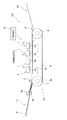
図1は、本発明に係る第1実施形態のインクジェットプリンタの全体的な構成を示す概略側面図である。図2は、インク供給機構の概略構成図である。なお、図2においては、1つのインクジェットヘッド1に対するインク供給機構69が示されているが、他のインクジェットヘッド1についても同様である。図1及び図2に示すように、インクジェットプリンタ101は、4つのインクジェットヘッド1を有するカラーインクジェットプリンタであり、インクジェットプリンタ101全体の動作を制御する制御装置16と、インクジェットヘッド1にインクを供給するインク供給機構69とを有している。このインクジェットプリンタ101には、図中左方に給紙部11が、図中右方に排紙部12が、図中紙面奥側にメンテナンスユニット30(図6参照)がそれぞれ構成されている。
<First Embodiment>
FIG. 1 is a schematic side view showing the overall configuration of the ink jet printer according to the first embodiment of the present invention. FIG. 2 is a schematic configuration diagram of the ink supply mechanism. In FIG. 2, the
図1に示すように、インクジェットプリンタ101の内部には、給紙部11から排紙部12に向かって用紙Pが搬送される用紙搬送経路が形成されている。給紙部11のすぐ下流側には、用紙を狭持搬送する一対の送りローラ5a、5bが配置されている。一対の送りローラ5a、5bは、用紙Pを給紙部11から図中右方に送り出すためのものである。用紙搬送経路の中間部には、搬送機構13が設けられている。この搬送機構13は、2つのベルトローラ6、7と、両ローラ6、7の間に架け渡されるように巻回されたエンドレスの搬送ベルト8と、搬送ベルト8によって囲まれた領域内に配置されたプラテン15とを含む。プラテン15は、インクジェットヘッド1と対向する位置において搬送ベルト8が下方に撓まないように搬送ベルト8を支持するものである。ベルトローラ7と対向する位置には、ニップローラ4が配置されている。ニップローラ4は、給紙部11から送りローラ5a、5bによって送り出された用紙Pを搬送ベルト8の外周面8aに押さえ付けるものである。
As shown in FIG. 1, a paper conveyance path through which the paper P is conveyed from the
図示しない搬送モータがベルトローラ6を回転させることによって、搬送ベルト8が走行される。これにより、搬送ベルト8が、ニップローラ4によって外周面8aに押さえ付けられた用紙Pを粘着保持しつつ排紙部12に向けて搬送する。なお、搬送ベルト8の表面には、弱粘着性のシリコン樹脂層が形成されている。
The
搬送ベルト8のすぐ下流側には、剥離プレート14が設けられている。剥離プレート14は、搬送ベルト8の外周面8aに粘着されている用紙Pを外周面8aから剥離して、図中右方の排紙部12に向けて導くように構成されている。
A
4つのインクジェットヘッド1は、4色(マゼンタ、イエロー、シアン、ブラック)のインクに対応して、搬送方向に配列された状態で図示しないヘッドフレームに固定されている。つまり、このインクジェットプリンタ101は、ライン式プリンタである。このヘッドフレームは、図示しない昇降機構によって、4つのインクジェットヘッド1と共に昇降可能となっている。後述するように、制御装置16は、4つのインクジェットヘッド1が、印刷位置(図1及び図8(a)参照)、退避位置(図8(b)参照)、ワイプ位置(図7(c)及び図7(d)参照)のいずれかに配置されるように、昇降機構を制御する。
The four
図2に示すように、インクジェットヘッド1は、リザーバユニット76と、リザーバユニット76の下端に接続されたヘッド本体2とをそれぞれ有している。リザーバユニット76は、インク供給機構69から供給されたインクをその内部で貯溜しつつ、貯溜したインクをヘッド本体2に供給するものであり、その内部に4つのインク流入流路77が形成されている。各インク流入流路77は、リザーバユニット76の上面に開口するインク流入口77aからインクの貯溜部(リザーバ)を通過し、さらに分岐してヘッド本体2(流路ユニット9)の上面に開口する2つのインク供給口105bに接続されている。なお、後述するように、各インク流入流路77に接続された2つのインク供給口105bは、同一のマニホールド流路105(図3参照)に対応するものである。
As shown in FIG. 2, the
ヘッド本体2は、搬送方向に直交した方向に長尺な細長い直方体形状となっている。また、図1に示すように、ヘッド本体2の底面が搬送ベルト8の外周面8aに対向するインク吐出面2aとなっている。インクジェットヘッド1が印刷位置に配置されているとき、搬送ベルト8によって搬送される用紙Pが4つのヘッド本体2のすぐ下方側を順に通過する際に、この用紙Pの上面すなわち印刷面に向けてインク吐出面2aから各色のインクが吐出されることで、用紙Pの印刷面に所望のカラー画像を形成できるようになっている。
The head
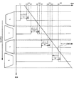
次に、図3〜図5を参照しつつ、ヘッド本体2について説明する。図3は、ヘッド本体2の平面図である。図4は、図3の一点鎖線で囲まれた領域の拡大図である。なお、図4では説明の都合上、アクチュエータユニット21の下方にあって破線で描くべき圧力室110、アパーチャ112及び吐出口108を実線で描いている。図5は、図4に示すV−V線に沿った部分断面図である。
Next, the
図3に示すように、ヘッド本体2には、4つのアクチュエータユニット21が、流路ユニット9の上面9aに固定されている。図4に示すように、流路ユニット9は、圧力室110等を含むインク流路が内部に形成されている。アクチュエータユニット21は、各圧力室110に対応した複数のアクチュエータを含んでおり、図示しないドライバICに駆動されることによって、圧力室110内のインクに選択的に吐出エネルギーを付与する機能を有する。
As shown in FIG. 3, four
図3に示すように、流路ユニット9は、一方向に延在した直方体形状を有している。流路ユニット9の内部には、アクチュエータユニット21と対向するように、流路ユニット9の長手方向(主走査方向)に千鳥状に配列された互いに独立する4つのマニホールド流路105が形成されている。各マニホールド流路105は、流路ユニット9の上面9aに開口すると共に主走査方向に並んだ2つのインク供給口105bを有している。この2つのインク供給口105bは、リザーバユニット76の同一のインク流入流路77(図2参照)に接続されている。つまり、流路ユニット9の上面9aには、4つのインク流入流路77それぞれに対応して2つずつ、計8個のインク供給口105bが開口している。また、各マニホールド流路105は、互いに平行に且つ主走査方向に延在するように分岐している複数の副マニホールド流路105aを有している。流路ユニット9の下面には、多数の吐出口108がマトリクス状に配置されたインク吐出面2aが形成されている。圧力室110も流路ユニット9におけるアクチュエータユニット21の固定面において吐出口108と同様マトリクス状に多数配列されている。
As shown in FIG. 3, the
本実施形態では、各マニホールド流路105に関して、等間隔に流路ユニット9の長手方向に並ぶ圧力室110の列が、短手方向に互いに平行に16列配列されている。各圧力室列に含まれる圧力室110の数は、アクチュエータユニット21の外形形状(台形形状)に対応して、その長辺側から短辺側に向かって次第に少なくなるように配置されている。吐出口108も、これと同様の配置がされている。
In the present embodiment, with respect to each
図4に示すように、流路ユニット9は、ステンレス鋼など金属材料からなる9枚のプレート122〜130から構成されている。これらプレート122〜130は、主走査方向に長尺な矩形状の平面を有する。
As shown in FIG. 4, the
これらプレート122〜130を互いに位置合わせしつつ積層することによって、プレート122〜130に形成された貫通孔同士が連結され、流路ユニット9内に、4つのマニホールド流路105、そして各マニホールド流路105に係る副マニホールド流路105aの出口から圧力室110を経て吐出口108に至る多数の個別インク流路132が形成される。
By laminating these
次に、流路ユニット9におけるインクの流れについて説明する。リザーバユニット76の各インク流入流路77からインク供給口105bを介して流路ユニット9内に供給されたインクは、マニホールド流路105において副マニホールド流路105aに分岐される。副マニホールド流路105a内のインクは、各個別インク流路132に流れ込み、絞りとして機能するアパーチャ112及び圧力室110を介して吐出口108に至る。
Next, the ink flow in the
このように、リザーバユニット76のインク流入流路77、当該インク流入流路77に接続されたインク供給口105bを有するマニホールド流路105及び当該マニホールド流路105に連通する複数の個別インク流路132が、1つの流路単位を構成している。そして、インクジェットヘッド1が、互いに独立した4つの流路単位を含んでいる。インク吐出面2aにおいては、各流路単位に係る複数の吐出口108が、アクチュエータユニット21の外形形状に対応する台形形状のユニット領域(分割領域)u1〜u4に配置されている。つまり、インク吐出面2aが、主走査方向に千鳥状に配置された4つのユニット領域u1〜u4(図9参照)を含んでいる。
As described above, the
図2に戻って、インク供給機構69について説明する。インク供給機構69は、インクタンク70と、インク供給ポンプ72と、切替バルブ73とを有している。そして、インクタンク70と切替バルブ73とがインク供給管71によって接続されている。また、切替バルブ73とリザーバユニット76の各インク流入流路77とがインク供給管74によってそれぞれ接続されている。インクタンク70は対応するインクジェットヘッド1に供給する色のインクを貯溜するものである。インク供給ポンプ72は、インク供給管71に取り付けられており、制御装置16のパージ制御部84(図7参照)に制御されてインクタンク70に貯溜されているインクを切替バルブ73を介してリザーバユニット76に強制的に送り出す。
Returning to FIG. 2, the
切替バルブ73は、インク供給管71を介してインクタンク70と連通する供給口73aと、インク供給管74を介してインク流入流路77とそれぞれ連通する4つの連通口73bとを有している。さらに、切替バルブ73は、制御装置16のパージ制御部84に制御されて、供給口73aと4つの連通口73bのうちいずれか1つと、又は、供給口73aと4つの連通口73b全てとを連通させる。パージ制御部84は、通常印刷を行う場合には、供給口73aと4つの連通口73b全てとを連通させている。インク供給ポンプ72は、インクタンク70から切替バルブ73に向かって、インクがその内部を自由に流通できる状態で停止している。これにより、インクタンク70からのインクがリザーバユニット76の全てのインク流入流路77に供給される。さらに、各インク流入流路77に供給されたインクが、マニホールド流路105及び個別インク流路132に供給される。インクジェットヘッド1が駆動され、吐出口108からインクが消費されれば、この消費量に対応したインクがインクタンク70からインクジェットヘッド1に自然に補給されることになる。
The switching
また、パージ制御部84は、吐出口108からインクを強制的に排出するパージ動作時においては、供給口73aと4つの連通口73bのいずれか1つを選択的に連通させる。このとき、インク供給ポンプ72が駆動されることによって、当該連通口73bに関する流路単位にのみ、インクタンク70からのインクが強制的に供給される。これにより、当該流路単位に対応するユニット領域u1〜u4に配置された吐出口108からインクが排出される。
Further, the
次に、図6を参照しつつ、メンテナンスユニット30について説明する。図6は、インクジェットプリンタ101の概略平面図である。図6に示すように、メンテナンスユニット30は、インクジェットヘッド1のメンテナンスを行うものであり、主走査方向に移動可能なXステージ31と、ワイプ部材51と、ホルダ52と、排出ガイド56と、Xステージ31の図6中左方側の面に固定された移動トレイ61とを有している。
Next, the
Xステージ31は、上方から見て4つのインクジェットヘッド1と対向するように、4つのインクジェットヘッド1の配列方向に沿って延在している。さらに、Xステージ31は、当該配列方向に関する両端近傍において、主走査方向に延在する一対のガイドレール32に摺動自在に支持されている。そして、Xステージ31は、その下部において、ガイドレール32と平行に延在するボールネジ33と螺合している。ボールネジ33の端部に接続されたメンテナンスモータ34が、ボールネジ33を回転させることによって、Xステージ31が主走査方向に往復移動可能となっている。制御装置16のヘッド位置制御部82は、メンテナンスモータ34の駆動を制御することによって、Xステージ31の主走査方向に関する移動を制御している。
The
ワイプ部材51は、インク吐出面2aを払拭するものであり、ゴムや樹脂などの弾性材料からなる矩形状の板部材である。ワイプ部材51は、4つのインクジェットヘッド1の配列方向の全幅よりも長く形成され、ホルダ52に支持されている。このとき、ワイプ部材51は、インク吐出面2aに対して所定の角度で傾斜するように、ホルダ52に支持されている。ホルダ52は、Xステージ31の上面に固定されている。排出ガイド56は、ホルダ52と共にXステージ31の上面に固定されており、ワイプ部材51の下方端部から廃インクトレイ62に向かって傾斜する傾斜面を有している。
The wipe
このように、ワイプ部材51を支持するホルダ52がXステージ31に固定されているため、ワイプ部材51が、主走査方向に関して移動可能になっている。なお、後述するように、ワイプ部材51によるインク吐出面の払拭方向は、図6中右方から左方に向かう方向となっている。
Thus, since the
移動トレイ61は、Xステージ31の図6中左方側の面に固定された矩形状の板部材であり、廃インクトレイ62を支持している。これにより、廃インクトレイ62は、Xステージ31の移動に伴って、主走査方向に移動可能となっている。廃インクトレイ62は、後述するように、インク受け位置に配置されたとき(図8(c)参照)、4つのインクジェットヘッド1と対向し得る広さ及び形状の底面を有している。
The moving
次に、図7を参照しつつ制御装置16について説明する。図7は、制御装置16の機能ブロック図である。図7示すように、制御装置16は、ヘッド駆動制御部81と、ヘッド位置制御部82と、メンテナンスユニット制御部83と、パージ制御部84とを有している。ヘッド駆動制御部81は、ドライバICを介してアクチュエータユニット21を駆動することによって、インクジェットヘッド1を制御するものである。ヘッド位置制御部82は、4つのインクジェットヘッド1が、印刷位置、退避位置及びワイプ位置のいずれかに配置されるように、図示しない昇降機構を制御するものである。メンテナンスユニット制御部83は、メンテナンスモータ34の駆動を制御することによって、Xステージ31の主走査方向に関する移動を制御するものである。すなわち、メンテナンスユニット制御部83は、ワイプ部材51によるインク吐出面2aの払拭動作(ワイプ動作)を制御する。
Next, the
パージ制御部84は、インクジェットヘッド1の流路内のインクを強制排出するパージ動作において、インク供給ポンプ72及び切替バルブ73を制御するものである。具体的には、パージ制御部84は、切替バルブ73及びインク供給ポンプ72を制御することによって、ユニット領域u1〜u4の払拭方向に関する配列の順に、各ユニット領域u1〜u4に配置された吐出口108から所定量のインクが強制排出(パージ)されるように、各ユニット領域u1〜u4に対応するインク流入流路77にインクを供給する。
The
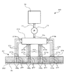
次に、図8を参照しつつ、インクジェットヘッド1のメンテナンスを行うときの、メンテナンスユニット30の動作について説明する。図8は、メンテナンスを行うときの各工程におけるメンテナンスユニット30の概略側面図である。インクジェットヘッド1のメンテナンスには、流路内のインクを強制排出するパージ動作と、パージ動作によってインク吐出面2aに残留したインクを払拭するワイプ動作とが含まれる。パージ動作を行うことによって、流路内の増粘したインクや不純物(気泡やゴミなど)が吐出口108から外部に排出される。また、ワイプ動作を行うことによって、インク吐出面2aに残留したインクや不純物がインク吐出面2aから除去される。インクジェットヘッド1のメンテナンスは、インクジェットプリンタ101の電源投入時、電源投入して所定時間が経過した後、印刷開始前、ユーザからの指示があったときなどに開始される。
Next, the operation of the
図8(a)に示すように、通常の印刷時においては、インクジェットヘッド1が、インク吐出面2aと搬送ベルト8の外周面8aとの間で所定の間隙を形成する印刷位置に配置されている。また、廃インクトレイ62が、4つのインクジェットヘッド1に係るインク吐出面2aと対向しない待機位置に配置されている。待機位置は、インクジェットヘッド1の並びの側方であって、主走査方向に関して左方に隣接した位置である(図6参照)。
As shown in FIG. 8A, during normal printing, the
インクジェットヘッド1のメンテナンスが開始されると、まず、制御装置16のヘッド位置制御部82が、図示しない昇降機構を制御して、インクジェットヘッド1を、インク吐出面2aがワイプ部材51の先端よりも高い位置ある退避位置に移動させる。そして、図8(b)に示すように、制御装置16のメンテナンスユニット制御部83が、メンテナンスモータ34を制御して、廃インクトレイ62が4つのインクジェットヘッド1に係るインク吐出面2aと対向するインク受け位置に配置されるように、Xステージ31を図8中右方に向かって移動させる。このとき、インクジェットヘッド1が退避位置に配置されているため、ワイプ部材51の先端が、インク吐出面2aに接触することがない。
When maintenance of the
廃インクトレイ62がインク受け位置に配置されると、図8(c)に示すように、制御装置16のヘッド位置制御部82が、昇降機構を制御して、インクジェットヘッド1を、退避位置と印刷位置との間であって、インク吐出面2aがワイプ部材51の先端よりも僅かに低い位置あるパージ位置に移動させる。
When the
この後、パージ動作及びワイプ動作が続く。図9を参照しつつ、パージ動作及びワイプ動作について説明する。図9は、ワイプ部材51の位置と各ユニット領域u1〜u4におけるパージ動作のタイミングとの関係を示したタイムチャートである。
Thereafter, a purge operation and a wipe operation are continued. The purge operation and the wipe operation will be described with reference to FIG. FIG. 9 is a time chart showing the relationship between the position of the wipe
インクジェットヘッド1がパージ位置に配置されると、図9に示すように、制御装置16のパージ制御部84が、切替バルブ73及びインク供給ポンプ72を制御することによって、払拭方向に関する上流側からユニット領域u1→ユニット領域u2→ユニット領域u3→ユニット領域u4の順に、各ユニット領域u1〜u4に配置された吐出口108から時間T1の間インクを強制排出するパージ動作を行う。これにより、吐出口108から所定量のインクが強制排出される。吐出口108から強制排出されたインクは、廃インクトレイ62に落下する。廃インクトレイ62に落下したインクは、図示しないポンプによって吸引されて廃インクタンクに貯溜される。
When the
また、メンテナンスユニット制御部83は、各ユニット領域u1〜u4のパージ動作の終了直後が、ワイプ部材51によるそれぞれのワイプ動作の開始となるよう、メンテナンスモータ34を駆動してXステージ31(ワイプ部材51)の移動を開始する。
Also, the maintenance
ここで、パージ制御部84は、ユニット領域u1〜u4に関するそれぞれのパージ動作の完了時刻が、ワイプ部材51が当該ユニット領域u1〜u4の払拭方向に関する上流側端部に到達する時刻、すなわち、ワイプ部材51によって当該ユニット領域u1〜u4の払拭が開始される時刻より時間T2(直前:時間T1より十分短い時間であって、例えば、0≦T2≦T1×0.1)だけ前の時刻になるように、インク供給ポンプ72を駆動する。言い換えると、パージ制御部84は、ユニット領域u1〜u4に関するパージ動作の開始時刻が、ワイプ部材51によって当該ユニット領域u1〜u4の払拭が開始される時刻より時間T1+時間T2前の時刻になるように、インク供給ポンプ72の駆動を開始する。
Here, the
また、メンテナンスユニット制御部83は、ワイプ部材51の先端がインク吐出面2aと接触した状態で、ワイプ部材51がインク吐出面2aの各ユニット領域u1〜u4を払拭方向に順に通過するように、Xステージ31を図8中左方に向かって移動させる。ワイパ部材51は、インク吐出面2aに対し、ユニット領域u1の払拭開始部より上流側で当接し、Xステージ31によって等速で移動される。上述したように、ユニット領域u1〜u4に関するパージ動作が完了した後、時間T2だけ遅れて、ワイプ部材51による当該ユニット領域u1〜u4の払拭が開始される。これにより、図8(c)及び図8(d)に示すように、ワイプ部材51が、払拭方向に関する上流側からパージ動作が完了した各ユニット領域u1〜u4を順に払拭して、当該ユニット領域u1〜u4に残存するインクを除去する。ワイプ部材51によって除去されたインクは、ワイプ部材51の斜面に沿って流下して排出ガイド56に達する。さらに、インクは、排出ガイド56の傾斜面を伝って廃インクトレイ62に排出される。そして、ワイプ部材51が当該ユニット領域u1〜u4を通過すると、当該ユニット領域u1〜u4の払拭が完了する。
In addition, the maintenance
図9に示すように、具体的には、時刻t11からユニット領域u1に関するパージ動作が開始され、時刻t12に当該パージ動作が完了する(時間T1)。本実施形態では、ワイプ部材51の移動が、パージ動作中に開始されている。そして、時刻t12から時間T2が経過した時刻t13において、ワイプ部材51がユニット領域u1の払拭を開始する。ワイプ部材51がユニット領域u1を払拭しているとき、時刻t21からユニット領域u2に関するパージ動作が開始され、時刻t22に当該パージ動作が完了する(時間T1)。そして、時刻t22から時間T2が経過した時刻t23において、ワイプ部材51がユニット領域u2の払拭を開始する。なお、ユニット領域u2の払拭開始時、ユニット領域u1とユニット領域u2とは払拭方向に関して一部が重なり合っているため、ワイプ部材51によるユニット領域u1の払拭が完了していない。
As shown in FIG. 9, specifically, the purge operation related to the unit region u1 is started from time t11, and the purge operation is completed at time t12 (time T1). In the present embodiment, the movement of the wipe
その後、ワイプ部材51が、ユニット領域u1の払拭を完了し、さらに、ユニット領域u2を払拭しているとき、時刻t31からユニット領域u3に関するパージ動作が開始され、時刻t32に当該パージ動作が完了する(時間T1)。そして、時刻t32から時間T2が経過した時刻t33において、ワイプ部材51がユニット領域u3の払拭を開始する。その後、ワイプ部材51が、ユニット領域u2の払拭を完了する。以下、ユニット領域u3、u4について同様処理が繰り返されることによって、全てのユニット領域u1〜u4に係るパージ動作及びワイプ動作が完了する。
Thereafter, when the wiping
このように、ワイプ部材51がユニット領域u1〜u4を払拭しているときに、払拭方向に関して、当該ユニット領域u1〜u4の下流側(前方)に隣接する別のユニット領域u1〜u4の吐出口108からインクの排出が開始されると共に、ワイプ部材51が当該別のユニット領域u1〜u4を払拭し始める直前(時間T2前)に、当該別のユニット領域の吐出口108から所定量のインクが排出し終わるように、メンテナンスユニット制御部83がメンテナンスモータ34の駆動を制御すると共に、パージ制御部84がインク供給ポンプ72及び切替バルブ73を制御する。
Thus, when the wiping
ここで、パージ動作を行う時間である時間T1はパージ動作におけるインク排出量を示している。このインク排出量はパージ動作を開始してから払拭されるまでの時間である残留時間によって決定される。パージ動作を行うことによってインク吐出面2aに残存したインクは、時間の経過に伴って負圧となっている吐出口108内に吸引される。このため、残留時間が経過するまでの間に吐出口108からインクと共に強制排出された気泡や不純物が吐出口108内に吸引されないように、インクを余分に排出する必要がある。インク排出量は、気泡や不純物を排出するために必要なインク量と上述した余分に排出するインク量とを足し合わせたものである。したがって、上記時間T1は、ワイプ部材51がユニット領域u1〜u4を払拭する時間、言い換えれば、ユニット領域u1〜u4の払拭方向に関する長さによって決定される。
Here, a time T1, which is a time for performing the purge operation, indicates an ink discharge amount in the purge operation. This ink discharge amount is determined by the remaining time, which is the time from the start of the purge operation to the wiping. The ink remaining on the
そして、4つのユニット領域u1〜u4の払拭が完了すると、メンテナンスユニット制御部83が、メンテナンスモータ34を制御して、廃インクトレイ62が待機位置に配置されるように、Xステージ31を図8中左に向かって移動させると共に、ヘッド位置制御部82が、昇降機構を制御して、インクジェットヘッド1を印刷位置に移動させる。以上で、メンテナンスが完了する。これに続き、印刷を行うならは、用紙Pが搬送され、全ての動作を終了するのであれば、各インク吐出面2aがキャップ(不図示)によって覆われて装置が停止する。
When the wiping of the four unit areas u1 to u4 is completed, the maintenance
以上、説明した本実施形態によると、ワイプ部材51がユニット領域u1〜u4を払拭し始める直前に、当該ユニット領域の吐出口108から所定量のインクが排出し終わる。このように、各ユニット領域u1〜u4において、吐出口108から所定量のインクが排出された後に、すぐにワイプ部材51で当該ユニット領域u1〜u4を払拭することができるため、吐出口108からインクを排出してからユニット領域u1〜u2を払拭するまでの時間が短くなる。これにより、吐出口108からインクを排出した後に、吐出口108に吸い込まれるインクの量が少なくなるため、パージ動作において、吐出口108から排出するインクの量を少なくすることができる。
As described above, according to the present embodiment described above, immediately before the wipe
また、インク供給機構69が、インク供給ポンプ72と、供給口73aと4つの連通口73bとの連通状態を切り替える切替バルブ73とを含んでいるため、インク供給機構69を簡易な構成で実現することができる。
In addition, since the
さらに、インク吐出面2aが一枚のノズルプレート130に形成されているため、インクジェットヘッド1を小型化することができる。
Furthermore, since the
<第2実施形態>
次に、図10及び図11を参照しつつ本発明の第2実施形態に係るインクジェットプリンタについて説明する。図10は、インク供給機構269の概略構成図である。図11は、ヘッド本体202の平面図である。なお、第1実施形態と実質的に同一の部材及び機能部については、第1実施形態と同一の符号を付して、その説明を省略する。
<Second Embodiment>
Next, an ink jet printer according to a second embodiment of the present invention will be described with reference to FIGS. FIG. 10 is a schematic configuration diagram of the
図10に示すように、インクジェットヘッド201は、リザーバユニット276と、リザーバユニット276の下端に接続されたヘッド本体202とを有している。リザーバユニット276は、インク供給機構269から供給されたインクをその内部で貯溜しつつ、貯溜したインクをヘッド本体202に供給するものであり、その内部に8つのインク流入流路277が形成されている。各インク流入流路277は、リザーバユニット276の上面に開口するインク流入口277aからヘッド本体202(流路ユニット209)の上面に開口するインク供給口205bに接続されている。
As shown in FIG. 10, the
図11に示すように、流路ユニット209の内部には、流路ユニット209の長手方向(主走査方向)に配列された互いに独立する8つのマニホールド流路205が形成されている。各マニホールド流路205は、流路ユニット9の上面9aに開口するインク供給口205bを有している。各インク供給口205bが、リザーバユニット276のインク流入流路277に接続されている。また、各マニホールド流路205は、互いに平行に且つ主走査方向に延在するように分岐している複数の副マニホールド流路205aを有している。
As shown in FIG. 11, eight independent
このように、リザーバユニット276のインク流入流路277、当該インク流入流路277に接続されたインク供給口205bを有するマニホールド流路205及び当該マニホールド流路205に連通する複数の個別インク流路132が、1つの流路単位を構成している。そして、インクジェットヘッド201が、互いに独立した8つの流路単位を含んでいる。そして、インク吐出面2aにおいては、各流路単位に係る複数の吐出口108が、主走査方向に配列された8つのユニット領域(分割領域)ua〜uh内にそれぞれ配置されている(図12参照)。なお、流路ユニット209の主走査方向(払拭方向)の一方から順に現れる2つずつのユニット領域ua〜uhが、アクチュエータユニット21の外形形状に対応する台形形状をそれぞれ構成している。したがって、ユニット領域ua〜uhの払拭方向に関する長さが、第1実施形態に係るユニット領域u1〜u4の半分となっている。
As described above, the
図10に戻って、インク供給機構269について説明する。インク供給機構269は、インクタンク70と、インク供給ポンプ72と、切替バルブ273とを有している。切替バルブ273は、インク供給管71を介してインクタンク70と連通する供給口73aと、インク供給管274を介してインク流入流路277とそれぞれ連通する8つの連通口273bとを有しており、インクジェットヘッド201に対するメンテナンスを行う場合に、制御装置16のパージ制御部84に制御されて供給口273aと8つの連通口73bのうちいずれか1つとを連通させる。このとき、インク供給ポンプ72が駆動されることによって、供給口273aと連通する連通口273bに関する流路単位にのみ、インクタンク70からのインクが強制的に供給される。
Returning to FIG. 10, the
図12をさらに参照しつつ、パージ動作及びワイプ動作について説明する。図12は、ワイプ部材51の位置と各ユニット領域ua〜uhにおけるパージ動作のタイミングとの関係を示したタイムチャートである。
The purge operation and the wipe operation will be described with further reference to FIG. FIG. 12 is a time chart showing the relationship between the position of the wipe
そして、図12に示すように、インクジェットヘッド201がパージ位置に配置されると、制御装置16のパージ制御部84が、切替バルブ273及びインク供給ポンプ72を制御することによって、払拭方向に関する上流側からユニット領域ua→ユニット領域ub→ユニット領域uc→ユニット領域ud→ユニット領域ue→ユニット領域uf→ユニット領域ug→ユニット領域uhの順に、各ユニット領域ua〜uhに配置された吐出口108から時間T3の間インクを強制排出するパージ動作を行う。
Then, as shown in FIG. 12, when the
ここで、パージ制御部84は、ユニット領域ua〜uhに関するそれぞれのパージ動作の完了時刻(ta2、tb2、tc2、td2、te2、tf2、tg2、th2)が、ワイプ部材51が当該ユニット領域ua〜uhの払拭方向に関する上流側端部に到達する時刻、すなわち、ワイプ部材51によって当該ユニット領域ua〜uhの払拭が開始される時刻より時間T2(図9に示す時間T2と同じ時間)だけ前の時刻になるように、インク供給ポンプ72を駆動する。言い換えると、パージ制御部84は、ユニット領域ua〜uhに関するパージ動作の開始時刻(ta1、tb1、tc1、td1、te1、tf1、tg1、th1)が、ワイプ部材51によって当該ユニット領域ua〜uhの払拭が開始される時刻より時間T3+時間T2前の時刻になるように、インク供給ポンプ72の駆動を開始する。
Here, the
また、メンテナンスユニット制御部83は、ワイプ部材51の先端がインク吐出面2aと接触した状態で、ワイプ部材51がインク吐出面2aの各ユニット領域ua〜uhを払拭方向に順に通過するように、Xステージ31を移動させる。上述したように、ユニット領域ua〜uhに関するパージ動作が完了した後、時間T2(ta2、tb2、・・・、th2)だけ遅れて、ワイプ部材51による当該ユニット領域ua〜uhの払拭が開始される。これにより、ワイプ部材51が、払拭方向に関する上流側からパージ動作が完了した各ユニット領域ua〜uhを順に払拭して、当該ユニット領域ua〜uhに残存するインクを除去する。なお、ワイパ部材51が、ユニット領域uaより払拭方向の上流側でインク吐出面2aに当接し、その後等速移動される点は先の第1実施形態と同じである。
Further, the maintenance
このように、ワイプ部材51がユニット領域ua〜uhを払拭しているときに、払拭方向に関して、当該ユニット領域ua〜uhの下流側(前方)に隣接する別のユニット領域ua〜uhの吐出口108からインクの排出が開始されると共に、ワイプ部材51が当該別のユニット領域ua〜uhの払拭方向に関する上流側の端部を払拭し始める直前(時間T2前)に、当該別のユニット領域の吐出口108から所定量のインクが排出し終わるように、メンテナンスユニット制御部83がメンテナンスモータ34の駆動を制御すると共に、パージ制御部84がインク供給ポンプ72及び切替バルブ73を制御する。
Thus, when the wipe
以上、説明した本実施形態によると、各ユニット領域ua〜uhにおいて、吐出口108から所定量のインクが排出された後に、すぐにワイプ部材51で当該ユニット領域ua〜uhを払拭するため、吐出口108からインクを排出してからユニット領域ua〜uhを払拭するまでの時間が短くなる。これにより、吐出口108からインクを排出した後に、吐出口108に吸い込まれるインクの量が少なくなるため、パージ動作において、吐出口108から排出するインクの量を少なくすることができる。
As described above, according to the present embodiment described above, in each unit area ua to uh, after the predetermined amount of ink is discharged from the
第1実施形態と比較すると、ユニット領域ua〜uhの払拭方向に関する長さが、第1実施形態に係るユニット領域u1〜u4の半分となっているため、吐出口108からインクを排出してからユニット領域ua〜uhを払拭するまでの時間をさらに短くすることができる(時間T3<時間T1)。 Compared to the first embodiment, the length of the unit areas ua to uh in the wiping direction is half that of the unit areas u1 to u4 according to the first embodiment. The time until the unit areas ua to uh are wiped can be further shortened (time T3 <time T1).
<変形例>
上述の第2実施形態においては、マニホールド流路205毎に流路単位を形成する構成であるが、1又は複数のマニホールド流路205によって流路単位を形成する構成であってもよい。例えば、図13に示すように、払拭方向に関する両側に配置されたマニホールド流路205がそれぞれ1つの流路単位を形成し、その他のマニホールド流路205のうち、払拭方向に沿って順に現れる2つずつのマニホールド流路205をリザーバユニットで連通させることによって、当該2つずつのマニホールド流路205が1つの流路単位を形成する構成であってもよい。これにより、インク吐出面2aにおいて、払拭方向に配列された5つのユニット領域ui〜umが形成される。
<Modification>
In the second embodiment described above, the flow path unit is formed for each
そして、ワイプ部材51がユニット領域ui〜umを払拭しているときに、払拭方向に関して当該ユニット領域ui〜umと払拭方向に係る下流側(前方)に隣接する別のユニット領域ui〜umの吐出口108からインクの排出が開始される(ti1、tj1、tk1、tl1、tm1)と共に、ワイプ部材51が当該別のユニット領域ui〜umの払拭方向に関する上流側の端部を払拭し始める直前(時間T2前:図9に示す時間T2と同じ時間)に、当該別のユニット領域ui〜umの吐出口108から所定量のインクが排出し終わる(ti2、tj2、tk2、tl2、tm2)ように(時間T1:図9に示す時間T1と同じ時間)、メンテナンスユニット制御部83がメンテナンスモータ34の駆動を制御すると共に、パージ制御部84がインク供給ポンプ72及び切替バルブ73を制御する。
When the wipe
以上、本発明の好適な実施形態について説明したが、本発明は上述の実施形態に限られるものではなく、特許請求の範囲に記載した限りにおいて様々な変更が可能なものである。例えば、上述の第1及び第2実施形態においては、ワイプ部材51がユニット領域を払拭しているときに、払拭方向に関して当該ユニット領域と払拭方向に係る下流側に隣接する別のユニット領域の吐出口108からインクの排出が開始される構成であるが、ワイプ部材51がユニット領域を払拭する以前に、払拭方向に関して当該ユニット領域と払拭方向に係る下流側に隣接する別のユニット領域の吐出口108からインクの排出が開始される構成であってもよい。
The preferred embodiments of the present invention have been described above. However, the present invention is not limited to the above-described embodiments, and various modifications can be made as long as they are described in the claims. For example, in the first and second embodiments described above, when the wipe
また、上述の第1及び第2実施形態においては、インク吐出面2aが一枚のノズルプレート130に形成されている構成であるが、図14(a)に示すように、インクジェットヘッドが、流路単位毎に独立した4つの分割ヘッド301を有しており、分割ヘッド301が払拭方向に関して千鳥状に配置されていてもよい。このとき、各分割ヘッド301のインク吐出面302aが台形形状を有するユニット領域となっている。なお、図14(b)に示すように、各分割ヘッド401のインク吐出面402aが矩形状を有するユニット領域となっていてもよい。これによると、分割ヘッド301、401を組み付けるだけで、容易の長尺のインクジェットヘッドを構成することができる。
In the first and second embodiments described above, the
1 インクジェットヘッド
2 ヘッド本体
2a インク吐出面
9 流路ユニット
16 制御装置
21 アクチュエータユニット
30 メンテナンスユニット
34 メンテナンスモータ
51 ワイプ部材
56 排出ガイド
61 移動トレイ
62 廃インクトレイ
69 インク供給機構
70 インクタンク
72 インク供給ポンプ
73 切替バルブ
73a 供給口
73b 連通口
76 リザーバユニット
77 インク流入流路
77a インク流入口
81 ヘッド駆動制御部
82 ヘッド位置制御部
83 メンテナンスユニット制御部
84 パージ制御部
101 インクジェットプリンタ
105b インク供給口
105 マニホールド流路
105a 副マニホールド流路
105b 各インク供給口
108 吐出口
u1〜u4 ユニット領域
ua〜ui ユニット領域
DESCRIPTION OF
Claims (4)
前記複数の流入流路のいずれかに選択的に液体を供給する供給手段と、
弾性材料からなるワイプ部材と、
前記ワイプ部材が前記吐出面と接触した状態で、前記ワイプ部材を前記一方向に移動させる移動機構と、
前記供給手段及び前記移動機構を制御する制御手段とを備えており、
前記吐出面において、同一の前記流入流路に連通する前記吐出口がそれぞれ配置された複数の分割領域が、前記一方向に関して配列されており、
前記制御手段は、
前記分割領域に配置された前記吐出口から所定量の液体が排出されるまで、各分割領域に対応する前記流入流路に液体を前記配列の順に供給するように、前記供給手段を制御すると共に、前記吐出口から所定量の液体が排出された順に各分割領域を前記ワイプ部材によって払拭するように、前記移動機構を制御し、且つ、前記ワイプ部材が前記分割領域を払拭し始める直前に、当該分割領域の吐出口から前記所定量の液体が排出し終わるように、前記供給手段及び前記移動機構を制御することを特徴とする記録装置。 A plurality of inflow channels having an inflow port through which liquid flows, a plurality of common liquid channels communicating with the different inflow channels, and an outlet of the common liquid channel from the outlet to the discharge surface. A liquid droplet ejection head having a plurality of individual liquid channels extending to the ejection port and extending in one direction;
Supply means for selectively supplying a liquid to any of the plurality of inflow channels;
A wipe member made of an elastic material;
A moving mechanism for moving the wipe member in the one direction in a state where the wipe member is in contact with the discharge surface;
Control means for controlling the supply means and the moving mechanism,
In the discharge surface, a plurality of divided regions in which the discharge ports communicating with the same inflow channel are respectively arranged are arranged in the one direction,
The control means includes
Controlling the supply means to supply liquid in the order of the arrangement to the inflow channel corresponding to each divided area until a predetermined amount of liquid is discharged from the discharge port arranged in the divided area. The movement mechanism is controlled so that each of the divided areas is wiped by the wipe member in the order in which a predetermined amount of liquid is discharged from the discharge port , and immediately before the wipe member starts wiping the divided area, The recording apparatus , wherein the supply unit and the moving mechanism are controlled so that the predetermined amount of liquid is completely discharged from the discharge port of the divided area .
前記制御手段が、前記複数の連通口のいずれかと前記供給口とが連通するように前記バルブを制御することを特徴とする請求項1に記載の記録装置。 The supply means is formed with a plurality of supply channels whose one end is connected to the inlet, a plurality of communication ports connected to the other end of the supply channel, and a supply port for supplying liquid. And a pump for supplying liquid to the supply port,
The recording apparatus according to claim 1, wherein the control unit controls the valve so that any one of the plurality of communication ports communicates with the supply port.
前記複数の分割ヘッドが、前記一方向に関して千鳥状に配置されていることを特徴とする請求項1又は2に記載の記録装置。
Each inflow channel and the common liquid channel and the individual liquid channel communicating with the inflow channel form a plurality of independent divided heads,
The recording apparatus according to claim 1, wherein the plurality of divided heads are arranged in a staggered manner with respect to the one direction.
Priority Applications (2)
| Application Number | Priority Date | Filing Date | Title |
|---|---|---|---|
| JP2008090043A JP4557032B2 (en) | 2008-03-31 | 2008-03-31 | Recording device |
| US12/403,373 US8132891B2 (en) | 2008-03-31 | 2009-03-12 | Image recording apparatus |
Applications Claiming Priority (1)
| Application Number | Priority Date | Filing Date | Title |
|---|---|---|---|
| JP2008090043A JP4557032B2 (en) | 2008-03-31 | 2008-03-31 | Recording device |
Publications (2)
| Publication Number | Publication Date |
|---|---|
| JP2009241381A JP2009241381A (en) | 2009-10-22 |
| JP4557032B2 true JP4557032B2 (en) | 2010-10-06 |
Family
ID=41116477
Family Applications (1)
| Application Number | Title | Priority Date | Filing Date |
|---|---|---|---|
| JP2008090043A Active JP4557032B2 (en) | 2008-03-31 | 2008-03-31 | Recording device |
Country Status (2)
| Country | Link |
|---|---|
| US (1) | US8132891B2 (en) |
| JP (1) | JP4557032B2 (en) |
Families Citing this family (4)
| Publication number | Priority date | Publication date | Assignee | Title |
|---|---|---|---|---|
| JP5236523B2 (en) * | 2009-02-19 | 2013-07-17 | 株式会社ミマキエンジニアリング | Printer apparatus and maintenance method thereof |
| EP3446878B1 (en) * | 2016-04-18 | 2020-09-09 | Konica Minolta, Inc. | Droplet ejecting device and method for maintaining droplet ejecting device |
| JP6784051B2 (en) * | 2016-04-18 | 2020-11-11 | ブラザー工業株式会社 | Inkjet recording device |
| CN114904822B (en) * | 2022-03-31 | 2023-09-26 | 上海果纳半导体技术有限公司 | Manipulator cleaning device, cleaning method and semiconductor device |
Citations (4)
| Publication number | Priority date | Publication date | Assignee | Title |
|---|---|---|---|---|
| JP2004058348A (en) * | 2002-07-26 | 2004-02-26 | Brother Ind Ltd | Inkjet printer |
| JP2006289648A (en) * | 2005-04-06 | 2006-10-26 | Olympus Corp | Image forming apparatus |
| JP2006327123A (en) * | 2005-05-30 | 2006-12-07 | Canon Finetech Inc | Method of cleaning face surface and inkjet system image forming apparatus |
| JP2007331116A (en) * | 2006-06-12 | 2007-12-27 | Brother Ind Ltd | Inkjet recorder |
Family Cites Families (4)
| Publication number | Priority date | Publication date | Assignee | Title |
|---|---|---|---|---|
| JPH10258523A (en) | 1997-03-21 | 1998-09-29 | Canon Aptecs Kk | Image-forming apparatus |
| DE69832039T2 (en) * | 1997-06-04 | 2006-05-24 | Seiko Epson Corp. | INK RADIATION HEAD AND INK RADIATOR |
| JP2004262108A (en) | 2003-03-03 | 2004-09-24 | Konica Minolta Holdings Inc | Inkjet recorder |
| JP3982519B2 (en) | 2004-05-28 | 2007-09-26 | ブラザー工業株式会社 | Inkjet recording device |
-
2008
- 2008-03-31 JP JP2008090043A patent/JP4557032B2/en active Active
-
2009
- 2009-03-12 US US12/403,373 patent/US8132891B2/en active Active
Patent Citations (4)
| Publication number | Priority date | Publication date | Assignee | Title |
|---|---|---|---|---|
| JP2004058348A (en) * | 2002-07-26 | 2004-02-26 | Brother Ind Ltd | Inkjet printer |
| JP2006289648A (en) * | 2005-04-06 | 2006-10-26 | Olympus Corp | Image forming apparatus |
| JP2006327123A (en) * | 2005-05-30 | 2006-12-07 | Canon Finetech Inc | Method of cleaning face surface and inkjet system image forming apparatus |
| JP2007331116A (en) * | 2006-06-12 | 2007-12-27 | Brother Ind Ltd | Inkjet recorder |
Also Published As
| Publication number | Publication date |
|---|---|
| US8132891B2 (en) | 2012-03-13 |
| US20090244174A1 (en) | 2009-10-01 |
| JP2009241381A (en) | 2009-10-22 |
Similar Documents
| Publication | Publication Date | Title |
|---|---|---|
| JP4784657B2 (en) | Recording device | |
| US8240809B2 (en) | Ink-jet recording apparatus | |
| JP5151473B2 (en) | Inkjet recording device | |
| US9050803B2 (en) | Liquid ejection head and image forming apparatus including the liquid ejection head | |
| JP5327446B2 (en) | Image forming apparatus | |
| JP5076299B2 (en) | Liquid ejector | |
| JP3217645B2 (en) | Ink jet recording apparatus and ink ejection recovery method in the apparatus | |
| JP4557032B2 (en) | Recording device | |
| US8465122B2 (en) | Liquid jetting apparatus | |
| JP2009226610A (en) | Recording device | |
| JP5120147B2 (en) | Maintenance method of liquid discharge head and liquid discharge apparatus | |
| US10131145B2 (en) | Ejection hole plate, liquid ejection head, and liquid ejection apparatus | |
| JP2014058095A (en) | Liquid discharge head, and image formation device | |
| JP4596057B2 (en) | Liquid ejection device | |
| JP2007331166A (en) | Inkjet recorder | |
| JP7131229B2 (en) | Liquid ejector | |
| JP4947009B2 (en) | Liquid ejection device | |
| JP5262365B2 (en) | Liquid discharge recording apparatus and ink jet recording apparatus | |
| JP2013111897A (en) | Ink-jet recorder | |
| JP4893692B2 (en) | Recording device | |
| JP2021049745A (en) | Liquid discharge device and control method for liquid discharge device | |
| JP5568920B2 (en) | Liquid ejection device | |
| JP2009226694A (en) | Liquid discharge apparatus | |
| JP4697169B2 (en) | Liquid ejection device and cap member | |
| JP2010228428A (en) | Recording device |
Legal Events
| Date | Code | Title | Description |
|---|---|---|---|
| A621 | Written request for application examination |
Free format text: JAPANESE INTERMEDIATE CODE: A621 Effective date: 20100128 |
|
| A977 | Report on retrieval |
Free format text: JAPANESE INTERMEDIATE CODE: A971007 Effective date: 20100402 |
|
| A131 | Notification of reasons for refusal |
Free format text: JAPANESE INTERMEDIATE CODE: A131 Effective date: 20100406 |
|
| A521 | Request for written amendment filed |
Free format text: JAPANESE INTERMEDIATE CODE: A523 Effective date: 20100604 |
|
| TRDD | Decision of grant or rejection written | ||
| A01 | Written decision to grant a patent or to grant a registration (utility model) |
Free format text: JAPANESE INTERMEDIATE CODE: A01 Effective date: 20100629 |
|
| A01 | Written decision to grant a patent or to grant a registration (utility model) |
Free format text: JAPANESE INTERMEDIATE CODE: A01 |
|
| A61 | First payment of annual fees (during grant procedure) |
Free format text: JAPANESE INTERMEDIATE CODE: A61 Effective date: 20100712 |
|
| R150 | Certificate of patent or registration of utility model |
Free format text: JAPANESE INTERMEDIATE CODE: R150 Ref document number: 4557032 Country of ref document: JP Free format text: JAPANESE INTERMEDIATE CODE: R150 |
|
| FPAY | Renewal fee payment (event date is renewal date of database) |
Free format text: PAYMENT UNTIL: 20130730 Year of fee payment: 3 |