JP4554291B2 - Signal quality estimation in wireless communication systems - Google Patents
Signal quality estimation in wireless communication systems Download PDFInfo
- Publication number
- JP4554291B2 JP4554291B2 JP2004209293A JP2004209293A JP4554291B2 JP 4554291 B2 JP4554291 B2 JP 4554291B2 JP 2004209293 A JP2004209293 A JP 2004209293A JP 2004209293 A JP2004209293 A JP 2004209293A JP 4554291 B2 JP4554291 B2 JP 4554291B2
- Authority
- JP
- Japan
- Prior art keywords
- signal
- field
- received
- difference
- column
- Prior art date
- Legal status (The legal status is an assumption and is not a legal conclusion. Google has not performed a legal analysis and makes no representation as to the accuracy of the status listed.)
- Expired - Fee Related
Links
Images


Classifications
-
- H—ELECTRICITY
- H04—ELECTRIC COMMUNICATION TECHNIQUE
- H04L—TRANSMISSION OF DIGITAL INFORMATION, e.g. TELEGRAPHIC COMMUNICATION
- H04L1/00—Arrangements for detecting or preventing errors in the information received
- H04L1/20—Arrangements for detecting or preventing errors in the information received using signal quality detector
- H04L1/208—Arrangements for detecting or preventing errors in the information received using signal quality detector involving signal re-encoding
-
- H—ELECTRICITY
- H04—ELECTRIC COMMUNICATION TECHNIQUE
- H04L—TRANSMISSION OF DIGITAL INFORMATION, e.g. TELEGRAPHIC COMMUNICATION
- H04L1/00—Arrangements for detecting or preventing errors in the information received
- H04L1/20—Arrangements for detecting or preventing errors in the information received using signal quality detector
Description
本発明は、一般的には通信システム、より詳細には無線通信システム内において信号品質を推定するための技術に係る。 The present invention relates generally to communication systems, and more particularly to techniques for estimating signal quality within a wireless communication system.
無線通信チャネルを通じて互いに通信する対のトランシーバを含む従来の無線通信システムにおいては、典型的には、その速度にてデータを伝送することができる複数の異なるデータ伝送速度を利用することができる。一般的には、データ速度が高くなるほど、システムは誤りに対して弱くなる。幾つかの状況下では、システムのデータ伝送速度を、少なくとも一部、環境の状態(environmental conditions)に基づいて、上方或いは下方に調節(適応化)することが必要となる。例えば、通信チャネル上の雑音や、トランシーバ障害は、システムをより低いデータ伝送速度にて動作させることを要請する。 In a conventional wireless communication system that includes a pair of transceivers that communicate with each other over a wireless communication channel, typically a number of different data transmission rates are available that can transmit data at that rate. In general, the higher the data rate, the weaker the system is against errors. Under some circumstances, it may be necessary to adjust (adapt) the data transmission rate of the system upwards or downwards, at least in part based on environmental conditions. For example, noise on the communication channel or transceiver failure requires the system to operate at a lower data transmission rate.
The Institute of Electrical and Electronics Engineers (IEEE) 802.11標準は、無線ローカルエリア網( WLAN)を通じて(伝送速度の)の媒体アクセス制御(medium access control, MAC)について規定する。このIEEE802.11標準については、Supplement to IEEE Standard for Information Technology - Telecommunications and Exchange Between Systems - Local Metropolitan Area Networks - Specific Requirements - Part 11: Wireless LAN Medium Access Control (MAC) and Physical Layer (PHY) Specifications, 1999 Editionなる表題のIEEE標準802.11に関する文献において説明されているため、これを参照されたい。この802.1標準に対する追加のエクステンション(additional extensions)として、IEEE標準802.11a及びIEEE標準802.11gが存在するが、これらに関しては、それぞれ、High Speed Physical Layer in the 5 GHz Band, Feb. 2000, 及びFurther Higher Data Rate Extension in the 2.4 GHz Band, Sept. 2000において説明されているため、これらについても参照されたい。802.11標準に従って動作する無線通信システムにおける速度の適応化は、通常は、送信機内の、媒体アクセス制御(MAC)レベルにおいて行なわれる。周知の速度適応化スキームは、典型的には、各データパケットが正常に伝送された後に(相手から)受信されるアクセスノレッジメントメッセージを通じて得られる情報に依存する。 The Institute of Electrical and Electronics Engineers (IEEE) 802.11 standard specifies medium access control (MAC) over wireless local area networks (WLANs). For the IEEE 802.11 standard, see Supplement to IEEE Standard for Information Technology-Telecommunications and Exchange Between Systems-Local Metropolitan Area Networks-Specific Requirements-Part 11: Wireless LAN Medium Access Control (MAC) and Physical Layer (PHY) Specifications, 1999 Please refer to this document because it is described in the literature on IEEE Standard 802.11 entitled Edition. Additional extensions to the 802.1 standard include IEEE standard 802.11a and IEEE standard 802.11g, which are related to High Speed Physical Layer in the 5 GHz Band, Feb. 2000, and Furter Higher, respectively. See also Data Rate Extension in the 2.4 GHz Band, Sept. 2000. Speed adaptation in a wireless communication system operating according to the 802.11 standard is typically done at the medium access control (MAC) level in the transmitter. Known rate adaptation schemes typically rely on information obtained through access knowledge messages received (from the other party) after each data packet has been successfully transmitted.
アクノレッジメントメッセージの存在は、データパケットが正常に受信されたことを示し、アクノレッジメントメッセージの不在は、通常は、誤りの発生として解釈される。送信機内で行なわれる、データ速度を変更すべきか否かの決定は、連続して受信されたアクノレッジメントの数に応答して行なわれる。正しく受信されたデータがある数を超えると、送信機は、典型的には、データ伝送速度をより高い速度に切換える。同様に、連続して発生した誤りがある数を超えると、送信機は、データ伝送速度をより低い速度に切換える。受信されたアクノレッジメントに基づくこの従来の速度切換方法は、単純であるという長所を有する。ただし、この方法では、しばしば、送信機のデータ伝送速度が、高すぎる或いは低すぎる値に切換えられ、このため、システムのスループットが劣化する。例えば、実際にはシステムによってそれより高い速度をサポートすることができるのに、より低いデータ速度に切換えた場合、スループットは著しく劣化する。システムがサポートできるより高いデータ速度に切換えることにも問題があり、この場合は、パケット誤り率(PER)、ビット誤り率(BER)或いはフレーム誤り率(FER)が上昇する。
従って、とりわけ無線通信システムにおけるデータ伝送速度を制御するために利用できる受信された信号の信号品質の正確な推定値を得るための方法であって、従来の無線通信システムにおいて見られた上述の問題を解決することができる方法が要請される。 Accordingly, a method for obtaining an accurate estimate of the signal quality of a received signal that can be used to control the data transmission rate, in particular in a wireless communication system, the above-mentioned problems found in conventional wireless communication systems. There is a need for a method that can solve this problem.
本発明は、無線通信システム内で用いるための、典型的にはベースバンド信号から成る受信された信号の信号品質値を正確に推定するための方法を提供する。この信号品質の推定値は、一つの実施例においては、無線通信システムと関連する受信機内において、無線通信システムのデータ伝送速度を、システム内の変化する状態に合わせて調節(適合化)するために用いられる。このような変化する状態としては、例えば、システムと関連する無線通信チャネル内の障害、無線通信チャネルを通じて通信するトランシーバ内の障害等が含まれる。信号がチャネルを通過する能力に悪影響を及ぼすチャネル障害には、例えば、同一チャネル干渉(co-channel interference)、遅延信号干渉(delayed signal interference)、(例えば、相互変調生成物からの)ナローバンド干渉(narrowband interference)、熱雑音(thermal noise)等が含まれる。本発明によると、信号品質の推定値は、少なくとも一部、受信されたデータパケットのある特定の部分に基づいて得られる。 The present invention provides a method for accurately estimating a signal quality value of a received signal, typically a baseband signal, for use in a wireless communication system. This estimate of signal quality, in one embodiment, is used in a receiver associated with the wireless communication system to adjust (adapt) the data transmission rate of the wireless communication system to the changing conditions in the system. Used for. Such changing conditions include, for example, a failure in a wireless communication channel associated with the system, a failure in a transceiver communicating through the wireless communication channel, and the like. Channel impairments that adversely affect the ability of the signal to pass through the channel include, for example, co-channel interference, delayed signal interference, narrowband interference (eg, from intermodulation products) ( Narrowband interference), thermal noise, etc. are included. According to the present invention, an estimate of signal quality is obtained based at least in part on a certain part of the received data packet.
本発明の一面によると、無線通信チャネルを含む無線システム内で用いる、受信された信号の信号品質を推定するための方法が開示される。この方法は、無線通信チャネルから、実質的に固定的なやり方にて変調及び符号化された少なくとも一つの欄を含む信号を受信するステップと、少なくとも一つの参照欄を、少なくとも一部、この少なくとも一つの欄及びチャネル推定信号に基づいて生成するステップを含む。このチャネル推定信号は、無線通信チャネルの少なくとも一つの特性を表す。この方法は、さらに、信号品質の推定値を、受信された信号内の少なくとも一つの欄及び生成された少なくとも一つの参照欄の関数として生成するステップを含む。 According to one aspect of the invention, a method for estimating signal quality of a received signal for use in a wireless system including a wireless communication channel is disclosed. The method includes receiving from a wireless communication channel a signal including at least one field that is modulated and encoded in a substantially fixed manner, and at least partially including at least one reference field. Generating based on one column and the channel estimation signal. This channel estimation signal represents at least one characteristic of the wireless communication channel. The method further includes generating an estimate of signal quality as a function of at least one field in the received signal and at least one reference field generated.
本発明のもう一面によると、無線通信チャネルを通じて通信を行うように構成されたトランシーバであって送信機と受信機を含む少なくとも一つのトランシーバを備える無線システム内で用いるための、該少なくとも一つのトランシーバのデータ伝送速度を制御するための方法が開示される。この方法は、無線通信チャネルから、実質的に固定的なやり方にて変調及び符号化された少なくとも一つの欄を含む信号を受信するステップと、少なくとも一つの参照欄を、少なくとも一部、該少なくとも一つの欄とチャネル推定信号に基づいて生成するステップを含む。このチャネル推定信号は、無線通信チャネルの少なくとも一つの特性を表す。この方法はさらに、受信された信号内の該少なくとも一つの欄と該少なくとも一つの参照欄とを比較し、これに対応する差信号を生成するステップと、該差信号の関数としての信号品質推定値を生成するステップと、送信機のデータ伝送速度を、少なくとも一部、該信号品質推定値に基づいて修正するステップを含む。 According to another aspect of the invention, at least one transceiver for use in a wireless system comprising at least one transceiver configured to communicate over a wireless communication channel and including a transmitter and a receiver. A method for controlling the data transmission rate is disclosed. The method includes receiving from a wireless communication channel a signal that includes at least one column that is modulated and encoded in a substantially fixed manner, and at least partially including at least one reference column. Generating based on one column and the channel estimation signal. This channel estimation signal represents at least one characteristic of the wireless communication channel. The method further includes comparing the at least one field in the received signal with the at least one reference field and generating a corresponding difference signal, and a signal quality estimate as a function of the difference signal. Generating a value and modifying the data transmission rate of the transmitter based at least in part on the signal quality estimate.
本発明のこれら及びその他の特徴及び長所が、本発明の幾つかの実施例の以下の詳細な説明を、添付の図面との関連で読むことで明らかになるものである。 These and other features and advantages of the present invention will become apparent from the following detailed description of several embodiments of the present invention when read in conjunction with the accompanying drawings.
本発明は、このではIEEE802.11に準拠する直交周波数分割多重(orthogonal frequency division multiplexing, OFDM)無線通信システムの背景内で説明される。ただし、本発明は、この無線通信システム或いは任意の特定の無線通信システムに制限されるものではない。むしろ、本発明は、より一般的に、無線通信システム内で用いるための、受信されたベースバンド信号の信号品質を正確に推定するための技法に適用できるものである。この信号品質の推定は、本発明の一面においては、無線システム内でのデータ伝送速度を最適に制御するために用いられる。本発明は、とりわけIEEE802.11標準との関連で用いるのに適するが、本発明は他の標準(standard)、並びに非標準(non-standard)システムとの関連で用いることもできる。 The present invention will now be described in the context of an orthogonal frequency division multiplexing (OFDM) wireless communication system compliant with IEEE 802.11. However, the present invention is not limited to this wireless communication system or any specific wireless communication system. Rather, the present invention is more generally applicable to techniques for accurately estimating the signal quality of a received baseband signal for use in a wireless communication system. This signal quality estimation is used in one aspect of the invention to optimally control the data transmission rate within the wireless system. Although the present invention is particularly suitable for use in the context of the IEEE 802.11 standard, the present invention can also be used in the context of other standard as well as non-standard systems.
図1は、本発明の方法がその内部で実現されることが考えられる一例としての無線通信システム100を示す。この一例としての無線通信システム100は対のトランシーバ102、104を含み、これらはこれら2つのトランシーバ102、104の間に設定された通信チャネル106を介して互いに通信する。チャネル106は無線通信リンクから成り、これには、例えば、無線周波数(radio frequency, RF)、赤外(infrared, IR)、マイクロ波等が含まれるが、ただし、代替の通信媒体を用いることもできる。チャネル106は、それと関連するあるデータ速度(data rate)を有し、これによって、その特定の媒体上で秒当り何個のサンプルを伝送することができるか決まる。トランシーバ102は、一つの好ましい実施例においては、チャネル106から信号を受信するための受信機108、及びチャネル106上に信号を送出するための送信機110を備える。同様に、トランシーバ104も、受信機114及び送信機112を備える。本発明との関連で用いるのに適する受信機及び送信機は当業者においては周知である。従って、これら受信機及び送信機の詳細な説明はここでは割愛する。
FIG. 1 shows an exemplary
受信されたベースバンド信号の信号品質の推定値は、例えば、無線通信チャネル106を通じての伝送の際のデータ伝送速度を適応化(調節)するために用いることができる。本発明の一面においては、信号品質の推定は、好ましくは、ある与えられたトランシーバ、例えば、トランシーバ102内の、受信機側、例えば、受信機108の所で決定される。データ伝送速度適応化方法(data transmission rate adaptation methodology)内で用いられる場合は、少なくとも通信チャネル106を通じての信号品質の推定を表す信号品質の推定値は、典型的には、送信機がチャネル106を通じての伝送の際のデータ伝送速度を設定するために、トランシーバ102内の対応する送信機102に供給される。受信機108は、一つの好ましい実施例においては、この信号品質の推定値を、受信されたベースバンド信号の特定の部分を処理することによって得るが、この特定の部分は、例えば、データフレーム、或いは制御フレーム(例えば、アクノレッジメントメッセージ)から成る。前述のように、信号がチャネル106を通過する能力に悪影響を及ぼすチャネル障害には、例えば、同一チャネル干渉、遅延信号干渉、ナローバンド干渉、熱雑音等が含まれる。チャネル伝達特性及びトランシーバ障害が準静的対称性(quasi-static symmetric)であるものと想定すると、アクノレッジメントメッセージは、本質的に、実際に送信されたデータと同一の信号劣化を受け、このため実質的に同一の品質を有するとみなすことができる。
The estimate of the signal quality of the received baseband signal can be used, for example, to adapt (adjust) the data transmission rate during transmission through the
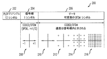
単に一例として、図2A及び2Bは、この一例としての無線通信システム内で伝送されるフレームを表す、標準のIEEE802.11物理層のコンバージェンス手続き(physical layer convergence procedure, PLCP)のフレームフォーマット200を示す。マルチキャリアシステム、並びに単一キャリアシステムにおいては、IEEE802.11標準は、各フレームは、プリアンブル202、信号(SIGNAL)欄204、及びデータ欄206を含むべきことを指定する。プリアンブル202は、主として同期の目的に用いられる12個の直交周波数分割多重(OFDM)シンボルを含む。信号(SIGNAL)欄204及びデータ欄206の一部は、主としてペイロードデータの長さ及び速度を指定するために用いられるPLCPヘッダ(図2B参照)を形成する。
By way of example only, FIGS. 2A and 2B illustrate a standard IEEE 802.11 physical layer convergence procedure (PLCP)
図2Bに示すように、このPLCPヘッダは、速度(RATE)欄(4ビット)、予約欄(1ビット)、長さ(LENGTH)欄(12ビット)、偶数パリティビット(1ビット)、テールビット(6ビット)、及びサービス(SERVICE)欄(16ビット)を含む。変調との関連では、長さ欄、速度欄、予約ビット及びパリティビット(及びこれに付加された6個の“零”から成るテールビット)から、信号欄204と呼ばれ、48個のサンプルを含む、一つの独立したOFDMシンボルが構成される。6個の“零”から成るテールビットはPLCPヘッダ内に、IEEE802.11仕様に従ってデータ(DATA)欄206を復号する際に必要となる、速度欄及び長さ欄を、確実に、かつ、タイムリーに検出する目的で挿入される。
As shown in FIG. 2B, the PLCP header includes a rate (RATE) column (4 bits), a reserved column (1 bit), a length (LENGTH) column (12 bits), an even parity bit (1 bit), and a tail bit. (6 bits) and a service (SERVICE) column (16 bits). In the context of modulation, the length field, the speed field, the reserved bits and the parity bits (and the tail bits consisting of 6 “zeros” appended to it) are called the
プリアンブル202及び信号(SIGNAL)欄204は、伝送されたデータフレームの同期及び受信を容易にするために、ペイロードデータと比較して単純かつ頑丈な、ある固定されたやり方にて変調及び符号化される。例えば、IEEE802.11a/g OFDMマルチキャリアシステムにおいては、プリアンブル及び信号欄は、二進位相偏移キーイング(binary phase shift keying,BPSK)と二進畳込み符号化(binary convolutional coding, BCC)という頑丈な組合わせと、1/2なる符号化レート(R)を採用する。データ(DATA)欄206を構成するペイロードデータの長さは可変とされ、信号(SIGNAL)欄204による指定に従って、データパケット毎に様々な符号化レート及び/或いは変調方式を用いて符号化される。例えば、IEEE802.11標準は、データを変調するための様々な変調方式をサポートし、これらには二進位相偏移キーイング(BPSK)、直交位相偏移キーイング(quadrature phase shift keying, QPSK)、16点直交振幅変調(16-point quadrature amplitude modulation, 16-QAM)、及び64点QAM(64-QAM)が含まれる。図2は、IEEE802.11標準によってサポートされるこれら変調方式の各々に対する信号点配置(signal constellation)を示す。例えば、信号点配置208及び210はBPSK変調を示し、信号点配置212はQPSK変調を示し、信号点配置214は16-QAMを示し、信号点配置216は64-QAMを示す。
The
データ(DATA)欄206内に伝送されるデータは可変のOFDMシンボル数を含み、データ速度及び/或いは変調方式も変化するが、信号(SIGNAL)欄については、上述のように、常に、同一のやり方にて、例えば、IEEE802.11仕様に従って、BPSK変調方式を用いて1/2なる符号化レートにて変調及び符号化される。伝送されるフレーム200の信号欄については、常に、既知の変調方式及び符号化レートが採用されるために、受信されたフレームの、期待される信号欄を容易に予測することができる。このため、一つの好まし実施例においては、受信されたフレームの信号欄内に含まれる実際の情報が、ペイロードデータとは実質的に独立した、正確な信号品質の推定値を得るために用いられる。
The data transmitted in the data (DATA)
802.11標準に対する少なくとも上述の802.11a及び802.11gエクステンション(extensions)においては、信号(SIGNAL)欄は、24ビットを含み、これらが1/2なる符号化レートにて符号化及びBPSK変調され、この結果、当業者においては理解できるように、図2Aに示すような信号点配置208内に、+1或いは−1の位相の所に、48個のサンプルが位置することとなる。この信号(SIGNAL)欄は、誤り無しに検出できるものと想定される。この想定は、信号欄は、通常は、パケットの残りの部分(例えば、データ欄)と比較して、より頑丈なやり方にて符号化及び変調されるために妥当なものである。更に、仮に、受信された信号欄の復調及び復号に誤りが発生したとしても、この場合は、残りのパケットは検出されない。
In at least the above mentioned 802.11a and 802.11g extensions to the 802.11 standard, the SIGNAL field contains 24 bits, which are coded and BPSK modulated at a coding rate of 1/2, resulting in As can be understood by those skilled in the art, 48 samples are located at the phase of +1 or −1 in the
本発明の一つの実施例においては、ある与えられた受信されたパケットの固定的に変調及び/或いは符号化された部分(例えば、IEEE802.11パケット内の受信された信号欄)がチャネル状態に関して補正された元の変調及び符号化スキーム(つまり、チャネル補正された変調スキーム)を表す参照欄(reference field)と比較され、信号品質の推定値は、受信された欄と参照欄との間の差の関数として得られる。好ましくは、信号品質の推定を表す信号品質指標(signal quality indication)が受信された各パケットに対して得られる。上述のように、この信号品質指標は、通信チャネルのデータ伝送速度を動的に適応化(調節)するために用いられる。こうすることで、無線通信システムのデータスループット(data throughput)が最適化される。 In one embodiment of the invention, a fixed modulated and / or encoded portion of a given received packet (eg, received signal field in an IEEE 802.11 packet) is related to channel conditions. Compared to a reference field that represents the corrected original modulation and coding scheme (ie, the channel corrected modulation scheme), an estimate of the signal quality is obtained between the received field and the reference field. Obtained as a function of difference. Preferably, a signal quality indication representing an estimate of signal quality is obtained for each received packet. As described above, this signal quality indicator is used to dynamically adapt (adjust) the data transmission rate of the communication channel. In this way, the data throughput of the wireless communication system is optimized.
本発明のもう一つの実施例においては、信号品質は、代替の方式、例えば、これに限定されるものではないが、受信された信号の固定的に変調・符号化された部分(例えば、PLCPヘッダ)の、信号対雑音比(signal-to-noise ratio, SNR)、ビット誤り率(bit error rate, BER)、巡回冗長符号(cyclic redundancy code, CRC)及び/或いは検査合計(checksum)を測定することによって決定される。この実施例においても、この信号品質は、データ速度適応化技術に用いられる。例えば、測定されたSNRがある閾値より低い場合はデータ速度は下げられ、測定されたSNRが所定の閾値より高い場合はデータ速度は増加される。同様に、PLCPに関するBER或いは検査合計を利用することもできる。例えば、BER或いは検査合計が、それぞれ、ある閾値と比較され、測定されたBER或いは検査合計が所定の閾値より高いか低いかに基づいて、データパケットのデータ速度が変化される。例えば、測定値としてCRCが用いられる場合は、CRCを用いて訂正された誤りの数がある指定される数を超えた場合、データパケットのデータ速度は低減される。 In another embodiment of the present invention, the signal quality is determined in an alternative manner, such as, but not limited to, a fixed modulated and encoded portion of the received signal (eg, PLCP Measure signal-to-noise ratio (SNR), bit error rate (BER), cyclic redundancy code (CRC) and / or checksum To be determined. Again, this signal quality is used in data rate adaptation techniques. For example, if the measured SNR is below a certain threshold, the data rate is reduced, and if the measured SNR is above a predetermined threshold, the data rate is increased. Similarly, the BER or checksum for PLCP can be used. For example, the BER or checksum is compared to a certain threshold, respectively, and the data rate of the data packet is changed based on whether the measured BER or checksum is higher or lower than a predetermined threshold. For example, when CRC is used as the measurement value, the data rate of the data packet is reduced if the number of errors corrected using CRC exceeds a specified number.
従来の速度切換えアプローチを用いた場合、データ伝送速度は、しばしば、必要以上に急速に低下される。このことは、高密度エリアにおいて特に顕著であるが、これは、アクノレッジメントメッセージの損失の原因ともなる様々な局間で発生する衝突の確率がより高くためであると考えられる。上述のように、アクノレッジメントメッセージが失われると、この方式では、送信機は、誤って、誤り(エラー)が発生したものと解釈し、このため、速度切換え手続きを不必要に発動される。これらの事情を踏まえて、本発明のもう一面においては、無線通信システムが、従来の速度切換え手続きと比較して、チャネル上の伝送速度を、より適切に、かつ、より高い信頼度にて、切換えることを可能とする、改善された速度切換え方法が提供される。更に、本発明によると、速度の切換えは、単一の増分幅だけでなく、必要に応じて、より大きな(或いは小さな)増分幅にて、選択的に、変更することが可能となる。 When using a conventional rate switching approach, the data transmission rate is often reduced more rapidly than necessary. This is particularly noticeable in high-density areas, which is believed to be due to the higher probability of collisions occurring between the various stations that cause loss of acknowledgment messages. As described above, when an acknowledgment message is lost, in this scheme, the transmitter erroneously interprets that an error has occurred, thus unnecessarily triggering a speed switching procedure. In view of these circumstances, in another aspect of the present invention, the wireless communication system is more appropriately and more reliable in transmission rate on the channel than the conventional rate switching procedure. An improved speed switching method is provided that allows switching. Furthermore, according to the present invention, the speed switching can be selectively changed not only with a single increment, but also with a larger (or smaller) increment as required.
一例としてのIEEE802.11a/gマルチキャリアシステムにおいては、速度の適応化は、送信機の内の、媒体アクセス制御(medium access control, MAC)層nにおいて遂行される。上述のように、本発明の一面によると、信号品質の推定値は、ある与えられたトランシーバと関連する、受信機側において決定され、対応する送信機に供給される。ある受信された信号(例えばあるパケット)に対応する信号品質の推定値は、一つの好ましい実施例においては、通信チャネルの、ある与えられた時間におけるある状態を表す。受信機は、信号品質を入りメッセージを処理することで得るが、この入りメッセージには、例えば、ペイロード及び/或いはアクノレッジメントデータが含まれる。チャネル伝達特性及びトランシーバ障害が準静的対称性であるものと想定すると、こうして処理されるメッセージは、実際に送られたデータと実質的に同一の劣化を受け、このため、これら2つは、信号品質に関しては、実質的に等しくなるものと想定できる。送信機は、自身の速度切換えの決定を、少なくとも一部、この信号品質の推定値に基づいて行う。 In the exemplary IEEE 802.11a / g multi-carrier system, rate adaptation is performed in the medium access control (MAC) layer n of the transmitter. As described above, according to one aspect of the invention, an estimate of signal quality is determined at the receiver side associated with a given transceiver and provided to a corresponding transmitter. A signal quality estimate corresponding to a received signal (eg, a packet), in one preferred embodiment, represents a state of the communication channel at a given time. The receiver obtains signal quality by processing the incoming message, which includes, for example, payload and / or acknowledgment data. Assuming that channel transfer characteristics and transceiver failures are quasi-static symmetries, the messages thus processed are subject to substantially the same degradation as the data actually sent, so these two are It can be assumed that the signal quality is substantially equal. The transmitter makes its decision to switch speed based at least in part on this signal quality estimate.
図3は、本発明の一面による、信号品質の推定値を計算するための方法を実現するための、一例としての回路300のブロック図を示す。回路300は、例えば、ある与えられたトランシーバの受信機内に実現される。代替として、回路300は、受信機の外部、例えば、送信機内に組み込むことも、或いはトランシーバの別個のセクション、例えば、コントローラ(図示せず)内に実現することもできる。この一例としての信号品質推定方法は、一つの好ましい実施例においては、参照信号欄(reference SIGNAL field)を生成する過程を含む。これは、最初に、受信された信号欄を復調及び復号し、次に、この信号(SIGNAL)欄を符号化及び変調し、最後に、あるチャネル推定値(channel estimate)を加えることで達成される。この結果として得られる参照信号(SIGNAL)欄は、例えば、チャネル、送信機及び/或いは受信機と関連する、チャネル雑音及び障害等の寄与は含まれない。次に、受信された信号欄が、この参照信号欄と比較される。この結果、48個の複素値(complex values)が得られるが、これらのある一つの値は、信号欄内対応する48個のサンプルの一つと対応する。これら48個の複素値の大きさ(magnitude)を取り、これらを総和することで、その特定のパケットに対する一つの信号品質推定値が得られる。
FIG. 3 shows a block diagram of an
説明を簡単にするために、以下の説明においては、この一例としての回路300は複数の機能ブロックから成るものとして説明される。これら機能ブロックには、回路300の第一の入力301に接続された復号・符号化・変調ブロック302、この復号・符号化・変調ブロック302の出力に接続された乗算器304、回路300の第一の入力301に接続された遅延ブロック306、遅延ブロック306と乗算器304の各出力に接続された比較器308、この比較器308の出力に接続された規模(大きさ)ブロック310、及びこの規模ブロック310の出力に接続された累算器(integrator)312が含まれる。一つの好ましい実施例においては、この累算器312の出力によって回路300の出力318が形成される。図面においては、これらは別個の機能ブロックとして示されるが、当業者においては理解できるように、この一例としての回路300を構成するこれら一つ或いは複数のブロックの少なくとも一部を一つ或いは複数の他の機能ブロックと結合及び/或いは一体化することも、こうして結合された機能ブロックのある部分を共有することもできる。以下では、回路300の動作についてより詳細に説明する。
For ease of explanation, in the following description, this
例えば、同相成分(I)と直交成分(Q)から構成されるある受信された信号は、好ましくは、実質的に並列に、復号・符号化・変調ブロック302と、遅延ブロック306に供給される。この受信された信号は、例えば、受信されたパケットの、既知の固定された変調及び符号化方式を用いて変調及び符号化された信号欄(SIGNAL field)或いはこの代替部分から成る。復号・符号化・変調ブロック302は、好ましくは、この受信された信号を、元の信号欄を含む元の送信された信号が回復されるようなやり方にて処理することができるように構成される。この元の送信された信号を回復するためには、最初に、少なくとも受信された信号欄が(例えば、スライサを用いて)復調され、(例えば、ビタビ復号器を用いて)復号される。信号欄の復号は、いずれにしても、典型的には、データ速度やデータパケットの長さ等の重要な情報を得るために遂行することが必要となる。次に、この信号欄が、元の送信されたパケットと実質的に同様なやり方にて(例えば、畳み込み符号化及びBPSK変調を用いて)符号化及び変調される。復号・符号化・変調ブロック302の出力は、こうして回復された信号欄を含むが、その後、これを用いて参照信号欄(reference SIGNAL field)が生成される。
For example, a received signal composed of an in-phase component (I) and a quadrature component (Q) is supplied to the decoding / encoding /
復号・符号化・変調ブロック302によって生成された回復された信号欄は、乗算器304に供給され、ここで、これは、この一例としての回路300の第二の入力320に供給される、チャネル推定信号(channel estimation signal)と結合される。このチャネル推定信号は、一つの好ましい実施例においては、チャネル特性の推定(値)を表し、これには、無線通信システム内の通信チャネルの影響(例えば、雑音、システム障害等)が含まれる。このチャネル推定信号は、例えば、典型的には、IEEE802.11 PLCPフレームのプリアンブル内に、この信号欄より先に送られる、訓練シンボル(例えば、短な及び/或いは長い訓練シンボル)から得られる。ただし、本発明から逸脱することなく、このチャネル推定信号を得るために、これとは異なる方法を用いることもできる。結果として、乗算器304の出力の所に参照信号欄が生成される。
The recovered signal field generated by the decoding / encoding /
この参照信号欄と、受信された信号欄の遅延されたバージョンとが、比較器308に供給される。受信された信号欄のこの遅延されたバージョンは、例えば、受信された信号欄を、関連するある固定された遅延値を有する、遅延ブロック306に通すことで生成される。本発明の一つの好ましい実施例においては、この遅延値(量)は、参照信号欄を(例えば、ブロック302及び304を用いて)生成するために要求される時間と実質的に等しくされ、このため、この具体的な量は、当業者においては理解できるように、回路300の特定の実現と関連する実際の遅延に依存する。こうして、受信された信号欄のこの遅延されたバージョンは、比較器308の所に、参照信号欄と実質的に同時に、到着することとなる。
This reference signal field and the delayed version of the received signal field are supplied to the
比較器308は、一つの好ましい実施例においては、その出力の所に差信号を生成するように構成され、これは、例えば、遅延された受信された信号欄から、参照信号欄を引くことで生成される。比較器308によって生成されるこの差信号は、本質的に、誤り信号(error signal)から成り、これは、一つの好ましい実施例においては、少なくともトランシーバ及び/或いは通信チャネルと関連するある特性(例えば、雑音等)に基づく。比較器308は、通信チャネルの品質を決定するが、これは、本発明の一面によると、受信された(未処理の)信号欄の信号点配置(constellation points)と、参照信号欄の対応する信号点配置とを比較することで行なわれる。チャネルの品質は、受信された信号欄信号点配置と参照信号欄の対応する信号点配置との間の距離(つまり、不一致度)に正比例する。この距離は、例えば、当業者においては理解できるように、ユークリッド距離(Euclidean distance)として測定される。
The
受信された信号欄の信号点配置が参照信号欄の対応する信号点配置により接近した場合は、これはチャネル品質の改善の指標である。同様に、受信された信号欄の信号点配置が参照信号欄の対応する信号点配置からより遠ざかった場合は、これはチャネル品質の劣化の指標である。こうして、信号品質の正確な推定値が、少なくとも一部、2つのセットの信号点配置間の差に基づいて得られる。 If the signal point arrangement in the received signal column is closer to the corresponding signal point arrangement in the reference signal column, this is an indicator of channel quality improvement. Similarly, if the signal point constellation in the received signal column is further away from the corresponding signal point constellation in the reference signal column, this is an indicator of channel quality degradation. Thus, an accurate estimate of signal quality is obtained based at least in part on the difference between the two sets of signal point constellations.
その後、規模(magnitude)ブロック310の所で、I成分とQ成分から構成されるこの差信号の規模(大きさ)が計算される。この規模は、一つの好ましい実施例においては、当業者においては周知のように、この差信号の、I成分とQ成分の二乗の平方根を取ることで決定される。本発明から逸脱することなく、この差信号の規模を決定するための他の方法を用いることもできる。その後、受信された信号欄内の48個のサンプルに対応する差信号の規模値(magnitude values)が、累算器(integrator)312によって加算され、この結果としての数値を用いて信号品質の推定値(signal quality estimation, SQ)が生成され、これが、この一例としての回路300の出力318の所に供給される。
Thereafter, at the magnitude block 310, the magnitude of the difference signal composed of the I component and the Q component is calculated. This magnitude is determined in one preferred embodiment by taking the square root of the square of the I and Q components of this difference signal, as is well known to those skilled in the art. Other methods for determining the magnitude of this difference signal may be used without departing from the invention. Thereafter, magnitude values of the difference signal corresponding to 48 samples in the received signal field are added by an
差信号の規模を得る方法に対する代替として、本発明のもう一つの実施例においては、差信号の電力測定値(power measurement)が得られる。規模の代りに、電力測定値を用いる方法では、長所として、平方根の計算が不要となり、実現コストを削減できる。受信された信号欄内の48個のサンプルに対応する差信号の電力測定値は、その後、累算器312によって、上述の差信号の規模値を処理するのと同様のやり方にて処理される。
As an alternative to the method of obtaining the magnitude of the difference signal, in another embodiment of the present invention, a power measurement of the difference signal is obtained. In the method using the power measurement value instead of the scale, as an advantage, the calculation of the square root is unnecessary, and the realization cost can be reduced. The difference signal power measurements corresponding to the 48 samples in the received signal column are then processed by
累算器312は、前の規模値を少なくとも一時的に格納する遅延ブロック316に接続された総和(summation)ブロック314を含む。累算器312は、一つの好ましい実施例においては、現在のサンプルに対応する規模値を前のサンプルに対応する規模値に加えるように構成される。この累算過程(integration procedure)をある与えられたパケットの信号欄(SIGNAL field)と関連する48個の全サンプルが処理されるまで遂行され、こうして、この与えられたパケットに対する平均規模値が得られる。遅延ブロック316は、好ましくは、ある与えられたパケットの信号欄内の、48個の全てのサンプルが処理された時点でリセットされる。本発明から逸脱することなく、規模値の平均を計算するための他の代替方法を用いることもできる。例えば、受信された信号欄内の48個のサンプルに対応する各規模値を少なくとも一時的にメモリ内に格納し、これらを例えば、48‐ビット加算器を用いて並列に一度に加算することもできる。
前述のように、受信された信号は、信号品質の推定値を得るために用いることができる、固定的に変調及び/或いは符号化された部分(例えば、ヘッダ)を含む。例えば、802.11タイプのパケットの場合は、受信された信号の少なくとも第二の部分(例えば、ペイロードデータ)は、固定的に変調及び/或いは符号化されることはなく、利用される変調及び/或いは符号化スキームは変化する。本発明のもう一面によると、受信された信号の第二の部分の変調及び/或いは符号化は、少なくとも一部、信号品質の推定値に基づいて変えられる。 As described above, the received signal includes a fixedly modulated and / or encoded portion (eg, a header) that can be used to obtain an estimate of signal quality. For example, in the case of 802.11 type packets, at least a second portion of the received signal (eg, payload data) is not permanently modulated and / or encoded, / Or the encoding scheme varies. According to another aspect of the invention, the modulation and / or encoding of the second portion of the received signal is varied based at least in part on the signal quality estimate.
本発明のもう一面によると、信号品質の推定値を決定するための方法の全体或いは一部が、トランシーバのデータ伝送速度を制御するための回路(図示せず)内で用いられる。このデータ伝送速度を制御するための回路は、ここに説明された本発明の方法の少なくとも一部を遂行するように構成されたコントローラ(図示せず)を含む。ここで用いられるコントローラなる用語は、例えば中央演算ユニット(CPU)及び/或いは他の処理回路(例えば、マイクロプロセッサ)等を含む、あらゆる処理デバイスを包含することを意図される。更に、これらコントローラ及び/或いは処理ブロックは、専用回路としてハードウェアにて実現することもできる。加えて、“コントローラ”なる用語は、複数のコントローラデバイスも包含し、あるコントローラデバイスと関連する様々な要素を他のコントローラデバイスと共有することも考えられる。更に、ここに説明された本発明の方法を遂行するための回路は、当業者においては理解できるように、少なくとも一部、複数のこれら回路を含む、一つの半導体デバイスとして実現することもできる。 According to another aspect of the invention, all or part of a method for determining an estimate of signal quality is used in a circuit (not shown) for controlling the data rate of the transceiver. The circuit for controlling the data transmission rate includes a controller (not shown) configured to perform at least a portion of the inventive method described herein. The term controller as used herein is intended to encompass any processing device including, for example, a central processing unit (CPU) and / or other processing circuitry (eg, a microprocessor). Furthermore, these controllers and / or processing blocks can also be realized by hardware as dedicated circuits. In addition, the term “controller” encompasses a plurality of controller devices, and it is also conceivable to share various elements associated with one controller device with other controller devices. Furthermore, the circuit for performing the method of the present invention described herein can be realized as a single semiconductor device including at least a part of the plurality of circuits, as will be understood by those skilled in the art.
上では本発明の幾つかの実施例が添付の図面を参照しながら説明されたが、本発明はこれら特定の実施例に制限されるものではなく、当業者においては、添付の請求項の範囲から逸脱することなく、様々な他の変更及び修正が可能である。例えば、本発明はIEEE802.11以外の標準(例えば、IEEE802.15)との関連で用いることも、更に、非標準システムとの関連で用いることもできる。 While several embodiments of the present invention have been described above with reference to the accompanying drawings, the present invention is not limited to these specific embodiments and those skilled in the art will recognize the scope of the appended claims. Various other changes and modifications can be made without departing from the invention. For example, the present invention can be used in connection with standards other than IEEE 802.11 (for example, IEEE 802.15), and can also be used in connection with non-standard systems.
100 無線通信システム
102、104 トランシーバ
106 通信チャネル
108、114 受信機
110、112 送信機
200 フレームフォーマット
202 プリアンブル
204 信号(SIGNAL)欄
206 データ欄
300 推定値計算回路
302 復号・符号化・変調ブロック
304 乗算器
306 遅延ブロック
308 比較器
310 規模ブロック
312 累算器
314 総和ブロック
316 遅延ブロック
100
Claims (14)
該受信された信号の少なくとも一つの欄と該無線通信チャネルの少なくとも一つの特性を表すチャネル推定信号とに少なくとも基づいて、少なくとも一つの参照欄を生成するステップと、
該少なくとも一つの参照欄と該受信された信号の少なくとも一つの欄との間の差の関数として、信号品質の推定値を生成するステップとを含み、
該少なくとも1つの参照欄を生成するステップは、
該受信された信号の少なくとも一つの欄を受信し、これから該少なくとも一つの欄と関連する複数の受信シンボルビットを回復し、
該受信シンボルビット内に潜在的に存在する一つ或いは複数の誤りを訂正することを含み、訂正された該受信シンボルビットは該少なくとも一つの欄内の当初送信されたシンボルビットに対応するものであり、該生成するステップはさらに、
該訂正された受信シンボルビットを符号化し、
符号化された該訂正された受信シンボルビットをベースバンド信号に変換し、そして、
該ベースバンド信号と該チャネル推定信号とを結合し、該ベースバンド信号と該チャネル推定信号とに少なくとも基づいて、該少なくとも一つの参照欄を生成する、ことを含み、
該信号品質の推定値を生成するステップが、該少なくとも一つの参照欄と関連する一つ或いは複数の信号点配置と該受信された信号内の該少なくとも一つの欄と関連する一つ或いは複数の対応する信号点配置との間の差を測定する処理を含む、方法。 A method for estimating the signal quality of a signal received from a wireless communication channel, the received signal comprising at least one column modulated and encoded in a fixed manner, the method comprising:
Generating at least one reference field based at least on a channel estimation signal representative of at least one field of the received signal and at least one characteristic of the wireless communication channel;
Generating an estimate of signal quality as a function of the difference between the at least one reference field and the at least one field of the received signal;
Generating the at least one reference field comprises:
Receiving at least one field of the received signal, and recovering a plurality of received symbol bits associated with the at least one field;
Correcting one or more errors potentially present in the received symbol bits, wherein the corrected received symbol bits correspond to the originally transmitted symbol bits in the at least one field. And the generating step further comprises:
Encoding the corrected received symbol bits;
Converting the encoded received symbol bits corrected to a baseband signal; and
Combining with said baseband signal and said channel estimation signal, based at least on the said baseband signal and said channel estimation signal to produce said at least one reference column, looking contains that,
Generating the signal quality estimate includes one or more signal constellations associated with the at least one reference field and one or more associated with the at least one field in the received signal; A method comprising measuring a difference between corresponding signal point constellations .
該受信された信号内の該少なくとも一つの欄と、関連する該一つ或いは複数の信号点配置と該少なくとも一つの参照欄と関連する該一つ或いは複数の対応する信号点配置とを(時間的に)整合させるステップと、
該受信された信号内の該少なくとも一つの欄内の複数のサンプルの少なくとも一部の各々に対して、該受信された信号内の該少なくとも一つの欄と該対応する少なくとも一つの参照欄との間の差を表す差信号を生成するステップと、を含む請求項1記載の方法。 Generating an estimate of the signal quality comprises:
The at least one column in the received signal, the associated one or more signal constellations and the one or more corresponding signal constellations associated with the at least one reference column (time); Step)
For each of at least some of the plurality of samples in the at least one column in the received signal, the at least one column in the received signal and the corresponding at least one reference column the method of claim 1 further comprising the steps of: generating a difference signal representing the difference between the.
該差信号の規模を決定するステップとをさらに含み、該信号品質の推定値が該差信号の該規模の関数である、請求項1記載の方法。 Generating a difference signal representative of a difference between the at least one field and the at least one reference field in the received signal;
The method of claim 1, further comprising: determining a magnitude of the difference signal, wherein the estimate of the signal quality is a function of the magnitude of the difference signal.
該差信号の電力を測定するステップとをさらに含み、該信号品質の推定値が該差信号の少なくとも該電力測定値の関数である、請求項1記載の方法。 Generating a difference signal representative of a difference between the at least one field and the at least one reference field in the received signal;
Measuring the power of the difference signal, wherein the estimate of signal quality is a function of at least the power measurement of the difference signal.
該方法が、更に、該第二の欄の変調及び符号化の少なくとも一方を、少なくとも一部、該信号品質の推定値に基づいて変化させるステップを含む、請求項1記載の方法。 Including a second column in which the received signal is variably modulated and encoded;
The method of claim 1, further comprising changing at least one of the modulation and coding of the second column based at least in part on the estimate of the signal quality.
該受信された信号の少なくとも一つの欄と該無線通信チャネルの少なくとも一つの特性を表すチャネル推定信号とに少なくとも基づいて、少なくとも一つの参照欄を生成するように構成されたプロセッサと、
該プロセッサに接続された比較器とを備え、該比較器が、該少なくとも一つの参照欄と該受信された信号の少なくとも一つの欄との間の差の関数として、信号品質の推定値を生成するように構成され、
該プロセッサが、
該受信された信号の少なくとも一つの欄を受信し、これから該少なくとも一つの欄と関連する複数の受信シンボルビットを回復するように構成されたスライサと、
該受信シンボルビット内に潜在的に存在する一つ或いは複数の誤りを訂正するよう構成された復号器とを含み、訂正された該受信シンボルビットは該少なくとも一つの欄内の当初送信されたシンボルビットに対応するものであり、該プロセッサはさらに、
該訂正された受信シンボルビットを符号化するように構成された符号器と、
符号化された該訂正された受信シンボルビットをベースバンド信号に変換するように構成された変調器と、
該ベースバンド信号と該チャネル推定信号とを結合し、該ベースバンド信号と該チャネル推定信号とに少なくとも基づいて、該少なくとも一つの参照欄を生成するように構成された乗算器とを備え、
該比較器は、該少なくとも一つの参照欄と関連する一つ或いは複数の信号点配置と該受信された信号内の該少なくとも一つの欄と関連する一つ或いは複数の対応する信号点配置との間の差を測定するようさらに構成されている、回路。 A circuit for estimating the signal quality of a signal received from a wireless communication channel, the received signal including at least one field modulated and encoded in a fixed manner, the circuit comprising:
A processor configured to generate at least one reference field based at least on at least one field of the received signal and a channel estimation signal representative of at least one characteristic of the wireless communication channel;
A comparator coupled to the processor, wherein the comparator generates an estimate of signal quality as a function of the difference between the at least one reference field and the at least one field of the received signal. Configured to
The processor
A slicer configured to receive at least one field of the received signal and to recover a plurality of received symbol bits associated therewith from the at least one field;
A decoder configured to correct one or more errors potentially present in the received symbol bits, wherein the corrected received symbol bits are the originally transmitted symbols in the at least one column Corresponding to the bit, the processor further comprising:
An encoder configured to encode the corrected received symbol bits;
A modulator configured to convert the encoded received symbol bits that have been corrected to a baseband signal;
A multiplier configured to combine the baseband signal and the channel estimation signal and to generate the at least one reference field based at least on the baseband signal and the channel estimation signal ;
The comparator includes one or more signal constellations associated with the at least one reference field and one or more corresponding signal constellations associated with the at least one field in the received signal. A circuit further configured to measure a difference between .
該受信された信号内の該少なくとも一つの欄と関連する該一つ或いは複数の信号点配置と該少なくとも一つの参照欄と関連する該一つ或いは複数の対応する信号点配置とを(時間的に)整合させるよう構成され、そして、
該受信された信号内の該少なくとも一つの欄内の複数のサンプルの少なくとも一部の各々に対して、該受信された信号内の該少なくとも一つの欄と該対応する少なくとも一つの参照欄との間の差を表す差信号を生成するよう構成されている、請求項8記載の回路。 The comparator is
The one or more signal constellations associated with the at least one field in the received signal and the one or more corresponding signal constellations associated with the at least one reference field (in time). Configured to match) and
For each of at least some of the plurality of samples in the at least one column in the received signal, the at least one column in the received signal and the corresponding at least one reference column 9. The circuit of claim 8 , wherein the circuit is configured to generate a difference signal representative of the difference between the two.
該受信された信号内の該少なくとも一つの欄と該少なくとも一つの参照欄との間の差を表す差信号を生成するよう構成され、そして、
該差信号の規模を決定するよう構成されており、該信号品質の推定値が該差信号の該規模の関数である、請求項8に記載の回路。 The comparator is
Configured to generate a difference signal representative of a difference between the at least one field and the at least one reference field in the received signal; and
9. The circuit of claim 8 , wherein the circuit is configured to determine a magnitude of the difference signal, and wherein the signal quality estimate is a function of the magnitude of the difference signal.
該受信された信号内の該少なくとも一つの欄と該少なくとも一つの参照欄との間の差を表す差信号を生成するよう構成され、そして、
該差信号の電力を測定するよう構成されており、該信号品質の推定値が該差信号の少なくとも該電力測定値の関数である、請求項8記載の回路。 The comparator is
Configured to generate a difference signal representative of a difference between the at least one field and the at least one reference field in the received signal; and
9. The circuit of claim 8 , wherein the circuit is configured to measure the power of the difference signal, and the estimate of the signal quality is a function of at least the power measurement of the difference signal.
該第二の欄の変調及び符号化の少なくとも一方を、少なくとも一部、該信号品質の推定値に基づいて変化させる、請求項8記載の回路。 A second column in which the received signal is variably modulated and encoded;
9. The circuit of claim 8 , wherein at least one of the modulation and encoding of the second column is varied based at least in part on the estimate of the signal quality.
Applications Claiming Priority (1)
| Application Number | Priority Date | Filing Date | Title |
|---|---|---|---|
| US10/621,862 US8503577B2 (en) | 2003-07-17 | 2003-07-17 | Signal quality estimation in a wireless communication system |
Publications (3)
| Publication Number | Publication Date |
|---|---|
| JP2005039839A JP2005039839A (en) | 2005-02-10 |
| JP2005039839A5 JP2005039839A5 (en) | 2007-04-19 |
| JP4554291B2 true JP4554291B2 (en) | 2010-09-29 |
Family
ID=33477122
Family Applications (1)
| Application Number | Title | Priority Date | Filing Date |
|---|---|---|---|
| JP2004209293A Expired - Fee Related JP4554291B2 (en) | 2003-07-17 | 2004-07-16 | Signal quality estimation in wireless communication systems |
Country Status (3)
| Country | Link |
|---|---|
| US (1) | US8503577B2 (en) |
| EP (1) | EP1499060A1 (en) |
| JP (1) | JP4554291B2 (en) |
Families Citing this family (29)
| Publication number | Priority date | Publication date | Assignee | Title |
|---|---|---|---|---|
| US20060007898A1 (en) * | 2003-12-23 | 2006-01-12 | Maltsev Alexander A | Method and apparatus to provide data packet |
| US7593347B2 (en) * | 2003-12-29 | 2009-09-22 | Intel Corporation | Method and apparatus to exchange channel information |
| JP4717555B2 (en) * | 2005-08-30 | 2011-07-06 | 京セラ株式会社 | COMMUNICATION SYSTEM, COMMUNICATION DEVICE, AND COMMUNICATION CONTROL METHOD |
| KR100763207B1 (en) * | 2006-05-03 | 2007-10-04 | 삼성전자주식회사 | Method and apparatus for transmitting/receiving uncompressed audio/video data and transmission frame structure |
| US20070263584A1 (en) * | 2006-05-09 | 2007-11-15 | Samsung Electronics Co., Ltd. | Method and apparatus for transmitting/receiving uncompressed audio/video data |
| US20070270103A1 (en) * | 2006-05-16 | 2007-11-22 | Samsung Electronics Co., Ltd. | Method and apparatus for transmitting/receiving uncompressed audio/video data |
| US20070268972A1 (en) * | 2006-05-16 | 2007-11-22 | Samsung Electronis Co., Ltd. | Method and apparatus for transmitting/receiving uncompressed AV data |
| US8144814B2 (en) * | 2006-05-22 | 2012-03-27 | Qualcomm Incorporated | Signal quality estimator |
| US20070291853A1 (en) * | 2006-06-19 | 2007-12-20 | Samsung Electronics Co., Ltd. | Method and apparatus for transmitting/receiving uncompressed data |
| US8379609B2 (en) * | 2007-03-29 | 2013-02-19 | Vixs Systems, Inc. | Multimedia client/server system with adjustable data link rate and range and methods for use therewith |
| US7984177B2 (en) * | 2007-04-30 | 2011-07-19 | Vixs Systems, Inc. | Multimedia client/server system with adjustable packet size and methods for use therewith |
| US9112645B2 (en) * | 2007-05-11 | 2015-08-18 | Microsoft Technology Licensing, Llc | Channel control based on error correction values |
| US9008066B2 (en) * | 2007-10-31 | 2015-04-14 | Qualcomm, Incorporated | Method and apparatus for signaling transmission characteristics in a wireless communication network |
| US20090109955A1 (en) * | 2007-10-31 | 2009-04-30 | Qualcomm Incorporated | Method and apparatus for improved frame synchronization in a wireless communication network |
| US8411765B2 (en) * | 2008-10-10 | 2013-04-02 | Ziva Corporation | Techniques and systems for wireless communications |
| KR20100060185A (en) * | 2008-11-27 | 2010-06-07 | 삼성전자주식회사 | Apparatus and method for controlling interference in wireless communication system |
| JP4898858B2 (en) | 2009-03-02 | 2012-03-21 | パナソニック株式会社 | Encoder, decoder and encoding method |
| US8223072B2 (en) * | 2009-04-29 | 2012-07-17 | Aruba Networks, Inc. | Multi-pattern wireless frame transmission |
| EP2474102A4 (en) | 2009-09-03 | 2016-06-22 | Ziva Corp | Techniques and systems for communications based on time reversal pre-coding |
| JP6046407B2 (en) * | 2012-07-23 | 2016-12-14 | ラピスセミコンダクタ株式会社 | OFDM modulation signal demodulator, receiving apparatus and receiving display apparatus |
| US20140029697A1 (en) * | 2012-07-24 | 2014-01-30 | Qualcomm Incorporated | GMSK-Based Modulation in a Wireless Local Area Network |
| US9456357B2 (en) | 2012-07-27 | 2016-09-27 | Aruba Networks, Inc. | Adaptive antenna pattern management for wireless local area networks |
| KR101727781B1 (en) * | 2013-10-14 | 2017-05-02 | 한국전자통신연구원 | Physical layer low energy communication method and apparatus |
| US9629004B2 (en) * | 2014-10-17 | 2017-04-18 | Microsoft Technology Licensing, Llc | Indication of wireless signal quality using detected errors in data |
| US10341739B2 (en) | 2016-05-16 | 2019-07-02 | Rovi Guides, Inc. | Methods and systems for recommending providers of media content to users viewing over-the-top content based on quality of service |
| AU2017266894A1 (en) * | 2016-05-16 | 2018-07-12 | Rovi Guides, Inc. | Methods and systems for presenting media listings based on quality of service at a user device |
| US10812851B2 (en) * | 2016-05-16 | 2020-10-20 | Rovi Guides, Inc. | Methods and systems for presenting media listings based on quality of service at a user device |
| TWI721520B (en) * | 2019-08-07 | 2021-03-11 | 新唐科技股份有限公司 | Operation device |
| CN112422210B (en) * | 2019-08-23 | 2022-11-01 | 微芯片技术股份有限公司 | Apparatus and method for signal-to-noise ratio and bit error rate estimation for wired local area networks |
Citations (7)
| Publication number | Priority date | Publication date | Assignee | Title |
|---|---|---|---|---|
| JP2001086092A (en) * | 1999-09-13 | 2001-03-30 | Matsushita Electric Ind Co Ltd | Ofdm communications equipment and detecting method |
| JP2002033685A (en) * | 2000-05-11 | 2002-01-31 | Matsushita Electric Ind Co Ltd | Interference canceller and interference elimination method |
| JP2002246958A (en) * | 2001-02-20 | 2002-08-30 | Mitsubishi Electric Corp | Mobile object communication system, multicarrier cdma transmitter and receiver thereof |
| JP2002319919A (en) * | 2001-04-24 | 2002-10-31 | Toyo Commun Equip Co Ltd | Power line communication apparatus |
| JP2003069530A (en) * | 2001-08-24 | 2003-03-07 | Mitsubishi Electric Corp | Multicarrier cdma receiver |
| JP2003348046A (en) * | 2002-05-24 | 2003-12-05 | Mitsubishi Electric Corp | Radio communication system, communication apparatus and reception quality measurement method |
| JP2004193670A (en) * | 2002-12-06 | 2004-07-08 | Samsung Electronics Co Ltd | Inverse spread method in wireless communication |
Family Cites Families (9)
| Publication number | Priority date | Publication date | Assignee | Title |
|---|---|---|---|---|
| JPH0746787B2 (en) | 1985-05-27 | 1995-05-17 | 日本電気株式会社 | Transmission quality measuring device |
| IE80898B1 (en) | 1989-09-28 | 1999-06-02 | Milliken Europ Nv | Stabilised fabrics |
| US6522696B1 (en) * | 1997-04-11 | 2003-02-18 | Agere Systems Inc. | Adaptive frequency correction in a wireless communications system, such as for GSM and IS54 |
| US6215827B1 (en) * | 1997-08-25 | 2001-04-10 | Lucent Technologies, Inc. | System and method for measuring channel quality information in a communication system |
| JP3741866B2 (en) | 1998-06-05 | 2006-02-01 | 富士通株式会社 | Adaptive modulation system |
| JP3843329B2 (en) | 2000-12-25 | 2006-11-08 | 株式会社日立国際電気 | Adaptive modulation control method |
| US6993311B2 (en) * | 2002-02-20 | 2006-01-31 | Freescale Semiconductor, Inc. | Radio receiver having an adaptive equalizer and method therefor |
| WO2003075485A1 (en) * | 2002-03-07 | 2003-09-12 | Nokia Corporation | Power control device and method for calibrating the power of a transmitter or receiver in a mobile communication network |
| CA2475442C (en) * | 2002-03-08 | 2011-08-09 | Aware, Inc. | Systems and methods for high rate ofdm communications |
-
2003
- 2003-07-17 US US10/621,862 patent/US8503577B2/en active Active
-
2004
- 2004-02-24 EP EP04250993A patent/EP1499060A1/en not_active Ceased
- 2004-07-16 JP JP2004209293A patent/JP4554291B2/en not_active Expired - Fee Related
Patent Citations (7)
| Publication number | Priority date | Publication date | Assignee | Title |
|---|---|---|---|---|
| JP2001086092A (en) * | 1999-09-13 | 2001-03-30 | Matsushita Electric Ind Co Ltd | Ofdm communications equipment and detecting method |
| JP2002033685A (en) * | 2000-05-11 | 2002-01-31 | Matsushita Electric Ind Co Ltd | Interference canceller and interference elimination method |
| JP2002246958A (en) * | 2001-02-20 | 2002-08-30 | Mitsubishi Electric Corp | Mobile object communication system, multicarrier cdma transmitter and receiver thereof |
| JP2002319919A (en) * | 2001-04-24 | 2002-10-31 | Toyo Commun Equip Co Ltd | Power line communication apparatus |
| JP2003069530A (en) * | 2001-08-24 | 2003-03-07 | Mitsubishi Electric Corp | Multicarrier cdma receiver |
| JP2003348046A (en) * | 2002-05-24 | 2003-12-05 | Mitsubishi Electric Corp | Radio communication system, communication apparatus and reception quality measurement method |
| JP2004193670A (en) * | 2002-12-06 | 2004-07-08 | Samsung Electronics Co Ltd | Inverse spread method in wireless communication |
Also Published As
| Publication number | Publication date |
|---|---|
| US8503577B2 (en) | 2013-08-06 |
| EP1499060A1 (en) | 2005-01-19 |
| JP2005039839A (en) | 2005-02-10 |
| US20050013391A1 (en) | 2005-01-20 |
Similar Documents
| Publication | Publication Date | Title |
|---|---|---|
| JP4554291B2 (en) | Signal quality estimation in wireless communication systems | |
| JP4982029B2 (en) | Adapting data transmission rates in wireless communication systems | |
| US7903538B2 (en) | Technique to select transmission parameters | |
| US9379863B2 (en) | Method for signaling information by modifying modulation constellations | |
| CA2245797C (en) | System and method for adaptive modification of modulated and coded schemes in a communication system | |
| US7130587B2 (en) | Communication quality estimation method, communication quality estimation apparatus, and communication system | |
| US9386585B2 (en) | Systems and methods for a data scrambling procedure | |
| US20130286961A1 (en) | Systems and methods for wireless communication of long data units | |
| US20090046771A1 (en) | Reception quality estimating apparatus, wireless communication system, and reception quality estimating method | |
| EP2569891B1 (en) | Channel quality estimation from raw bit error rate | |
| US20020114379A1 (en) | Adaptive modulation communication system | |
| CN110691340A (en) | Wireless vehicle communication involving retransmission of messages | |
| EP1363437B1 (en) | Communication quality estimation method, communication quality estimation apparatus, and communication system | |
| US7685500B2 (en) | Forward error correction coding in communication networks | |
| US9246642B2 (en) | Method of communication adapted to the transmission of data packets | |
| WO2017155435A1 (en) | Methods and transceivers for wireless communication in a packet based communication network | |
| US7826339B2 (en) | Hierarchical modulation reverse link interface node | |
| US20230396363A1 (en) | Symbol Interleaving for Parameter Estimation | |
| US10038583B2 (en) | Method and devices for transmitting and receiving multi-carrier symbols | |
| Huang et al. | Exploiting modulation scheme diversity in multicarrier wireless networks |
Legal Events
| Date | Code | Title | Description |
|---|---|---|---|
| A521 | Written amendment |
Free format text: JAPANESE INTERMEDIATE CODE: A523 Effective date: 20070302 |
|
| A621 | Written request for application examination |
Free format text: JAPANESE INTERMEDIATE CODE: A621 Effective date: 20070302 |
|
| A977 | Report on retrieval |
Free format text: JAPANESE INTERMEDIATE CODE: A971007 Effective date: 20091005 |
|
| A131 | Notification of reasons for refusal |
Free format text: JAPANESE INTERMEDIATE CODE: A131 Effective date: 20091013 |
|
| A521 | Written amendment |
Free format text: JAPANESE INTERMEDIATE CODE: A523 Effective date: 20100113 |
|
| A131 | Notification of reasons for refusal |
Free format text: JAPANESE INTERMEDIATE CODE: A131 Effective date: 20100203 |
|
| A601 | Written request for extension of time |
Free format text: JAPANESE INTERMEDIATE CODE: A601 Effective date: 20100430 |
|
| A602 | Written permission of extension of time |
Free format text: JAPANESE INTERMEDIATE CODE: A602 Effective date: 20100510 |
|
| A521 | Written amendment |
Free format text: JAPANESE INTERMEDIATE CODE: A523 Effective date: 20100603 |
|
| RD02 | Notification of acceptance of power of attorney |
Free format text: JAPANESE INTERMEDIATE CODE: A7422 Effective date: 20100603 |
|
| TRDD | Decision of grant or rejection written | ||
| A01 | Written decision to grant a patent or to grant a registration (utility model) |
Free format text: JAPANESE INTERMEDIATE CODE: A01 Effective date: 20100621 |
|
| A01 | Written decision to grant a patent or to grant a registration (utility model) |
Free format text: JAPANESE INTERMEDIATE CODE: A01 |
|
| A61 | First payment of annual fees (during grant procedure) |
Free format text: JAPANESE INTERMEDIATE CODE: A61 Effective date: 20100714 |
|
| FPAY | Renewal fee payment (event date is renewal date of database) |
Free format text: PAYMENT UNTIL: 20130723 Year of fee payment: 3 |
|
| R150 | Certificate of patent or registration of utility model |
Ref document number: 4554291 Country of ref document: JP Free format text: JAPANESE INTERMEDIATE CODE: R150 Free format text: JAPANESE INTERMEDIATE CODE: R150 |
|
| R250 | Receipt of annual fees |
Free format text: JAPANESE INTERMEDIATE CODE: R250 |
|
| R250 | Receipt of annual fees |
Free format text: JAPANESE INTERMEDIATE CODE: R250 |
|
| R250 | Receipt of annual fees |
Free format text: JAPANESE INTERMEDIATE CODE: R250 |
|
| S111 | Request for change of ownership or part of ownership |
Free format text: JAPANESE INTERMEDIATE CODE: R313113 |
|
| S533 | Written request for registration of change of name |
Free format text: JAPANESE INTERMEDIATE CODE: R313533 |
|
| R350 | Written notification of registration of transfer |
Free format text: JAPANESE INTERMEDIATE CODE: R350 |
|
| R250 | Receipt of annual fees |
Free format text: JAPANESE INTERMEDIATE CODE: R250 |
|
| R250 | Receipt of annual fees |
Free format text: JAPANESE INTERMEDIATE CODE: R250 |
|
| R250 | Receipt of annual fees |
Free format text: JAPANESE INTERMEDIATE CODE: R250 |
|
| S111 | Request for change of ownership or part of ownership |
Free format text: JAPANESE INTERMEDIATE CODE: R313111 |
|
| R350 | Written notification of registration of transfer |
Free format text: JAPANESE INTERMEDIATE CODE: R350 |
|
| LAPS | Cancellation because of no payment of annual fees |