JP4554044B2 - Voice recognition device for AV equipment - Google Patents
Voice recognition device for AV equipment Download PDFInfo
- Publication number
- JP4554044B2 JP4554044B2 JP2000227787A JP2000227787A JP4554044B2 JP 4554044 B2 JP4554044 B2 JP 4554044B2 JP 2000227787 A JP2000227787 A JP 2000227787A JP 2000227787 A JP2000227787 A JP 2000227787A JP 4554044 B2 JP4554044 B2 JP 4554044B2
- Authority
- JP
- Japan
- Prior art keywords
- signal
- monaural
- unit
- voice
- output
- Prior art date
- Legal status (The legal status is an assumption and is not a legal conclusion. Google has not performed a legal analysis and makes no representation as to the accuracy of the status listed.)
- Expired - Lifetime
Links
Images


Description
【0001】
【発明の属する技術分野】
本発明は、音声認識装置に関し、より特定的には、2チャンネルステレオを含むマルチチャンネルオーディオを再生するTV、ラジオ、オーディオシステムなどのAV機器に用いられ、スピーカからオーディオが拡声された状態であっても、音声によるAV機器の制御や、音声によるAV機器への情報入力等が可能であるAV機器用音声認識装置に関する。
【従来の技術】
従来、スピーカからオーディオが拡声された状態において音声認識を行う技術を記載した文献としては、特開平5−22779号公報(発明の名称「音声認識遠隔制御装置」)が知られている。
【0002】
図23は、上記公報に開示されている技術を用いた従来のAV機器用音声認識装置の構成を示すブロック図である。図23の音声認識装置は、1つのスピーカ201を持ったAV機器に用いられる。図23において、従来のAV機器用音声認識装置は、マイクロホン202と、音声認識部203と、エコーキャンセラ204とを備えている。
【0003】
以上のように構成された従来のAV機器用音声認識装置について、図24を用いてその動作を述べる。
図24は、図23の音声認識装置において、各構成要素に入力される、または各構成要素から出力される信号の時間波形を示す図である。図24において、スピーカ201からオーディオ信号が拡声された状態で、音声制御用の音声をユーザが発した場合を考える。
【0004】
スピーカ201からオーディオ信号が拡声されない状態で、ユーザが音声を発した場合は、マイクロホン202からは、図24の211に示す極めてS/Nのよい音声信号が出力される。ところが、スピーカ201に図24の212に示すTV番組のオーディオ信号が入力されていると、このスピーカ入力212と相似の図24の213に示す反響信号がマイクロホン202の出力に混入することになる。
【0005】
従って、マイクロホン202からは、ユーザ音声211と反響信号213とが加算された、図24の214に示す、ユーザ音声を認識するには極めてS/Nの悪い信号が出力される。このS/Nの悪いマイクロホン出力214が、音声認識部203に入力されても、音声認識部203で十分な音声認識結果が期待できないのは当然である。
【0006】
そこで、図23の音声認識装置では、スピーカ201からマイクロホン202に回り込む反響信号213を、エコーキャンセラ204内部の適応ディジタルフィルタで推定している。そして、エコーキャンセラ204内部の減算回路により、マイクロホン出力214からこの推定反響信号を差し引くことによって反響信号213を完全にキャンセルし、ユーザ音声211だけを抽出している。
【0007】
エコーキャンセラ204には、スピーカ201への入力信号であるスピーカ入力212が与えられる。エコーキャンセラ204内部の適応ディジタルフィルタは、このスピーカ入力212の波形と、内部に記憶されたスピーカ201からマイクロホン202までの反響路のインパルスレスポンスとから、反響信号215を推定する。次に、エコーキャンセラ204内部の減算回路が、マイクロホン出力214から、この推定反響信号215を差し引き、それによって、エコーキャンセラ出力216を得ている。
【0008】
このエコーキャンセラ出力216と、ユーザ音声の波形211とを比較すればわかるように、スピーカ201からオーディオが拡声された状態であっても、上記のようなエコーキャンセラ204の反響音打ち消し作用によって、音声認識部203が正確な音声認識を行うことが期待できる。
【0009】
しかしながら、図23の音声認識装置は、モノラルオーディオ方式のAV機器にしか対応しておらず、複数のスピーカを使用するマルチチャンネルオーディオ方式のAV機器には用いることができないという、大きな欠点を有していた。
【0010】
図25は、別の従来のAV機器用音声認識装置の構成を示すブロック図である。図25の音声認識装置は、2つのスピーカ221および222を持った2チャンネルオーディオ方式のAV機器に用いられる。
図25において、別の従来の音声認識装置は、マイクロホン223と、音声認識部224と、2つのエコーキャンセラ225および226とを備えている。
【0011】
この従来例は、スピーカ221からマイクロホン223に回り込む反響音と、スピーカ222からマイクロホン223に回り込む反響音とを、エコーキャンセラ225内部の適応ディジタルフィルタと、エコーキャンセラ226内部の適応ディジタルフィルタとで推定し、マイクロホンの出力信号から、この2つの推定値を差し引くことにより、ユーザ音声だけを抽出するものである。先の図23の音声認識装置と異なり、図25の音声認識装置は、ステレオ方式のAV機器に適用できる。
【0012】
しかしながら、図25の音声認識装置では、オーディオチャンネルの数だけエコーキャンセラを必要とするので、マルチチャンネルオーディオのAV機器に用いる場合には、極めて価格の高い音声認識装置になるという欠点を有していた。
さらに、このように複数のエコーキャンセラを用いたシステムにおいては、エコーキャンセラ間の相互干渉が起こるので、エコーキャンセラの適応動作が極めて不安定であり、適応失敗による反響音の増加や発振などが生じてしまうという大きな欠点も知られていた。
【0013】
【発明が解決しようとする課題】
AV機器用の音声認識装置においては、スピーカでオーディオを再生しながら音声認識が行えること、マルチチャンネルオーディオに対応できること、信頼性が高いこと、安価であることが強く要望されている。
【0014】
しかしながら、従来のAV機器用音声認識装置は、前述のように、オーディオチャンネルの数だけエコーキャンセラを必要とするので、マルチチャンネルオーディオ方式のAV機器に用いる場合には、極めて価格が高くなるという課題を有していた。
さらに、エコーキャンセラ間の相互干渉のためにエコーキャンセラの適応動作が極めて不安定となって、適応失敗による反響音の増加や発振などを生じ、その結果、音声認識性能が低下するという別の課題も有していた。
【0015】
それゆえに、本発明の目的は、スピーカからマルチチャンネル音響が出力されている状態で高精度の音声認識が行え、しかも安価であるような、マルチチャンネルAV機器用の音声認識装置を実現することである。
【0016】
【課題を解決するための手段および発明の効果】
第1の発明は、複数のスピーカを通じてマルチチャンネル音響を出力するAV機器に用いられ、マイクロホンを通じて入力されるユーザ音声を認識して、当該AV機器に所定の処理動作を行わせるための音声認識装置であって、
複数のスピーカへ向かうマルチチャンネル信号をモノラル化するモノラル化手段、
マイクロホンの出力(以下、マイクロホン出力)と、モノラル化手段の出力(以下、モノラル化信号)とが与えられ、当該モノラル化信号に基づいてマルチチャンネル音響の反響音を推定して、当該マイクロホン出力から当該反響音を除去する1つのエコーキャンセラ、
1つのエコーキャンセラの出力(以下、エコーキャンセラ出力)に基づいてユーザ音声を認識する音声認識手段を備えている。
【0017】
上記第1の発明では、マルチチャンネル信号をモノラル化して1つのエコーキャンセラに与え、その1つのエコーキャンセラがマイクロホン出力からマルチチャンネル音響の反響音を除去するので、チャンネル数に関わらずただ1つのエコーキャンセラを備えるだけで、スピーカからマルチチャンネル音響が出力されている状態で音声認識が行えるようになる。また、複数のエコーキャンセラを備える場合と異なり、エコーキャンセラ間の相互干渉が生じて音声認識性能が低下することもない。
【0018】
第2の発明は、第1の発明において、複数のスピーカへは、マルチチャンネル信号が入力されることを特徴としている。
【0019】
上記第2の発明では、複数のスピーカからマルチチャンネル音響が出力されるので、反響音をモノラル化信号で完全に打ち消すことはできない。しかし、マルチチャンネル信号のモノラル度が”1”に近ければ、反響音を概ね打ち消すことができる。少なくとも、マルチチャンネル信号のモノラル度が”0”でない限りは、反響音の一部を打ち消すことができる。
ここで、マルチチャンネル信号のモノラル度とは、その信号中に占める、全チャンネルに共通して含まれる成分(モノラル成分)の割合をいい、全チャンネルの信号が互いに全く無相関であれば、モノラル度は”0”、同一であれば、モノラル度は”1”となる。
【0020】
第3の発明は、第1の発明において、マルチチャンネル信号およびモノラル化信号のいずれかを複数のスピーカへと入力するための切り替え手段をさらに備えている。
【0021】
上記第3の発明では、複数のスピーカから、マルチチャンネル音響およびモノラル化音響のいずれかを選択的に出力させることができる。
【0022】
第4の発明は、第3の発明において、
モノラル化信号とエコーキャンセラ出力とに基づいてユーザ音声を検出する音声検出手段をさらに備え、
切り替え手段は、
音声検出手段によってユーザ音声が検出されていない時、マルチチャンネル信号を複数のスピーカへと入力し、
音声検出手段によってユーザ音声が検出されている時、モノラル化信号を複数のスピーカへと入力することを特徴としている。
【0023】
上記第4の発明では、音声認識を行う必要がない(ユーザ音声が検出されない)場合はマルチチャンネル音響を、音声認識を行う必要がある(ユーザ音声が検出されている)場合はモノラル化音響を出力させるので、十分に高い精度で音声認識が行えるようになる。
【0024】
第5の発明は、第3の発明において、
音声認識動作の起動を命令する起動命令手段、
音声認識動作の終了を命令する終了命令手段、および
起動命令手段および終了命令手段からの命令に応じて、音声認識手段を動作状態および待機状態のいずれかに設定する状態設定手段をさらに備え、
切り替え手段は、
状態設定手段によって音声認識手段が待機状態に設定されている時、マルチチャンネル信号を複数のスピーカへと入力し、
状態設定手段によって音声認識手段が動作状態に設定されている時、モノラル化信号を複数のスピーカへと入力することを特徴としている。
【0025】
上記第5の発明では、音声認識手段が待機状態(”OFF”状態)にある場合はマルチチャンネル音響を、動作状態(”ON”状態)にある場合はモノラル化音響を出力させるので、十分に高い精度で音声認識が行えるようになる。
【0026】
第6の発明は、第5の発明において、
マルチチャンネル信号のモノラル度を判定するモノラル度判定手段、および
マルチチャンネル信号を任意のモノラル度にモノラル化する任意度モノラル化手段をさらに備え、
モノラル化手段は、マルチチャンネル信号を完全にモノラル化し、
任意度モノラル化手段は、モノラル度判定手段の判定結果が予め定められたモノラル度よりも低い場合、マルチチャンネル信号を当該予め定められたモノラル度にモノラル化することを特徴としている。
【0027】
上記第6の発明では、マルチチャンネル信号のモノラル度が常に、予め定められたモノラル度以上になるので、音声認識手段が動作状態(”ON”状態)にある場合でも、立体感をあまり損なうことなく、高い精度で音声認識性能が行えるようになる(すなわち、立体感と音声認識性能とをバランスさせることができる)。
【0028】
第7の発明は、第5の発明において、
マルチチャンネル信号は、3チャンネル以上の信号であり、
マルチチャンネル信号を2チャンネル化する2チャンネル化手段をさらに備え、
モノラル化手段は、2チャンネル化手段の出力(以下、2チャンネル化信号)をモノラル化し、
切り替え手段は、マルチチャンネル信号、2チャンネル化信号およびモノラル化信号のいずれかを複数のスピーカへと入力することを特徴としている。
【0029】
上記第7の発明では、複数のスピーカから、マルチチャンネル音響、2チャンネル化音響およびモノラル化音響のいずれかを選択的に出力させることができる。
【0030】
第8の発明は、第7の発明において、
モノラル化信号とエコーキャンセラ出力とに基づいてユーザ音声を検出する音声検出手段をさらに備え、
切り替え手段は、
状態設定手段が音声認識手段を待機状態に設定している時には、マルチチャンネル信号を複数のスピーカへと入力し、
状態設定手段が音声認識手段を動作状態に設定しているが、音声検出手段によってユーザ音声が検出されていない時には、2チャンネル化信号を複数のスピーカへと入力し、
音声検出手段によってユーザ音声が検出されている時には、モノラル化信号を複数のスピーカへと入力することを特徴としている。
【0031】
上記第8の発明では、音声認識手段が待機状態(”OFF”状態)にある場合はマルチチャンネル音響を、動作状態(”ON”状態)にあるが音声認識を行う必要がない(ユーザ音声が検出されない)場合はマルチチャンネル音響を、音声認識を行う必要がある(ユーザ音声が検出されている)場合はモノラル化音響を出力させるので、待機状態における立体感をあまり損なうことなく、十分に高い精度で音声認識が行えるようになる。
【0032】
第9の発明は、第5の発明において、
モノラル化信号とエコーキャンセラ出力とに基づいて、エコーキャンセラにおいて反響音が十分に打ち消されているかを監視する打ち消し監視手段、
モノラル化信号とエコーキャンセラ出力とに基づいてユーザ音声を検出する音声検出手段、および
マルチチャンネル信号を減衰させる減衰手段をさらに備え、
減衰手段は、打ち消し監視手段の監視結果が打ち消し不十分を示している状態において、音声検出手段がユーザ音声を検出した時、マルチチャンネル信号を減衰させることを特徴としている。
【0033】
上記第9の発明では、反響音が十分に打ち消されていない状態でユーザ音声が検出された時、複数のスピーカから出力される音響のレベルを下げることによって、反響音の混入を抑制する。その結果、反響音が十分に打ち消されていない状態での音声認識性能が高まる。
【0034】
第10の発明は、第5の発明において、
エコーキャンセラは、
複数のスピーカとマイクロホンとの間の反響路のインパルスレスポンスを推定して、当該推定インパルスレスポンスと、モノラル化信号とから反響音を算出する適応ディジタルフィルタ、および
マイクロホン出力から、適応ディジタルフィルタの出力を減算する減算手段を含んでいる。
【0035】
上記第10の発明では、マイクロホン出力からマルチチャンネル音響の反響音を除去して、ユーザ音声だけを音声認識手段に与えることができる。
【0036】
第11の発明は、第10の発明において、切り替え手段によって複数のスピーカへの入力がマルチチャンネル信号からモノラル化信号へと切り替えられる際に、適応ディジタルフィルタの適応を促進するためのモノラル適応音を発生する適応音発生手段をさらに備えている。
【0037】
上記第11の発明では、スピーカへの入力がマルチチャンネル信号からモノラル化信号に切り替わる際に、複数のスピーカからモノラルの適応音響が出力されるので、もし切り替え直後のモノラル化音響が無音状態であっても、ディジタルフィルタが保持しているインパルスレスポンスを強制的に反響路のインパルスレスポンスに適応させることができる。
【0038】
第12の発明は、第10の発明において、
適応ディジタルフィルタの適応速度を制御する適応制御手段をさらに備え、
適応制御手段は、モノラル用の速い適応速度と、マルチチャンネル用の遅い適応速度とを持ち、状態設定手段が音声認識手段を動作状態に設定している時には速い適応速度を選択し、待機状態に設定している時には遅い適応速度を選択することを特徴としている。
【0039】
上記第12の発明では、エコーキャンセラ内の適応ディジタルフィルタの適応速度を、音声認識手段が動作状態に設定されている時には速い速度に、待機状態に設定されている時には遅い速度に制御するので、モノラル,マルチチャンネルそれぞれに好適なエコー打ち消しを行うことができる。
すなわち、スピーカから出力されるのがマルチチャンネル音響の場合は、適応ディジタルフィルタから見ると雑音であるステレオ成分が多いので、遅い適応速度とすることによって耐雑音性を高め、一方、モノラル化音響の場合は、ステレオ成分がないので、速い適応速度とすることによって、反響路のインパルスレスポンスの変動への追従性を高めることができる。
その結果、待機状態において優れたエコー打ち消し効果が実現され、動作状態へ移行した直後における音声認識性能が高まる。
【0040】
第13の発明は、第12の発明において、
適応制御手段へは、複数のスピーカに入力される信号がマルチチャンネル信号かモノラル信号かを示す識別信号が与えられ、
適応制御手段は、識別信号がモノラルを示す場合、状態設定手段が音声認識手段を動作状態に設定しているか待機状態に設定しているかに関わらず、速い適応速度を選択することを特徴としている。
【0041】
上記第13の発明では、複数のスピーカに入力される信号がマルチチャンネル信号かモノラル信号かを識別信号によって判別して、モノラル信号の場合は、状態設定手段が音声認識手段を動作状態に設定しているか待機状態に設定しているかに関わらず、速い適応速度を選択するので、反響路のインパルスレスポンスの変動への追従性が低下することがなく、その結果、待機状態において優れたエコー打ち消し効果が実現され、動作状態へ移行した直後における音声認識性能が高まる。
【0042】
第14の発明は、第10の発明において、
マルチチャンネル信号のモノラル度を判定するモノラル度判定手段、および
モノラル度判定手段の判定結果に基づいて、適応ディジタルフィルタの適応速度を制御する適応制御手段をさらに備えている。
【0043】
上記第14の発明では、マルチチャンネル信号のモノラル度に基づいて、適応ディジタルフィルタの適応速度を制御するので、様々なモノラル度を持ったマルチチャンネル信号に好適なエコー打ち消しを行うことができる。
すなわち、モノラル度が低い場合、適応速度を遅くして、耐雑音性を高める。
一方、モノラル度が高い場合、適応ディジタルフィルタから見ると雑音であるステレオ成分が少ないので、耐雑音性はあまり必要でない。よって、下記第15の発明のように、適応速度を速くすることによって、反響路のインパルスレスポンスの変動への追従性を高めることができる。その結果、特にモノラル度が高い場合に、優れたエコー打ち消し効果が実現でき、動作状態へ移行した直後における音声認識性能が高まる。
【0044】
第15の発明は、第14の発明において、適応制御手段は、マルチチャンネル信号のモノラル度が高いほど、適応ディジタルフィルタの適応速度を速くすることを特徴としている。
【0045】
第16の発明は、第10の発明において、
不揮発メモリをさらに備え、
不揮発メモリは、
電源が”OFF”される時、適応ディジタルフィルタによって推定されたインパルスレスポンスを取得して記憶し、
電源が”ON”される時、記憶している電源”OFF”時の推定インパルスレスポンスを適応ディジタルフィルタに与え、
適応ディジタルフィルタは、不揮発メモリから与えられた電源”OFF”時の推定インパルスレスポンスを初期値として、インパルスレスポンスの推定を開始することを特徴としている。
【0046】
上記第16の発明では、電源”OFF”時の推定インパルスレスポンスを記憶しておき、電源”ON”時、それを初期値としてインパルスレスポンスの推定を開始するので、”0”を初期値とする場合と比べ、電源”ON”直後の推定誤差が小さくなり、その結果、音声認識性能が高まる。
【0047】
第17の発明は、第5の発明において、
モノラル化信号とエコーキャンセラ出力とに基づいてユーザ音声を検出する音声検出手段をさらに備え、
起動命令手段は、ボタンが押されると、状態設定手段へ起動命令を発するようなボタンスイッチであり、
終了命令手段は、音声検出手段がユーザ音声を検出しない状態が予め定められた時間以上継続すると、状態設定手段へ終了命令を発する時限スイッチであることを特徴としている。
【0048】
上記第17の発明では、音声認識動作を自動的に終了できる。
【0049】
第18の発明は、第5の発明において、
モノラル化信号とエコーキャンセラ出力とに基づいてユーザ音声を検出する音声検出手段をさらに備え、
起動命令手段は、音声検出手段がユーザ音声を検出すると、状態設定手段へ起動命令を発する音声スイッチであり、
終了命令手段は、音声検出手段がユーザ音声を検出しない状態が予め定められた時間以上継続すると、状態設定手段へ終了命令を発する時限スイッチであることを特徴としている。
【0050】
上記第18の発明では、音声認識動作を自動的に開始・終了できる。
【0051】
【発明の実施の形態】
以下、本発明の実施の形態について、図面を参照しながら説明する。
最初に、本発明が用いられるAV機器について説明しておく。
図1は、本発明が用いられるAV機器の構成の一例を示すブロック図である。
図1に示されるAV機器は、テレビション放送を受信するためのテレビジョン受像機である。ここでいうテレビション放送では、マルチチャンネル(2チャンネルも含む;以下同様)の音響方式が採用されているとする。
【0052】
図1において、AV機器は、アンテナ1と、受信部2と、AV処理部3と、コントローラ4と、コントロールパネル5と、マイクロホン6と、音声認識装置7と、ディスプレイユニット8と、スピーカユニット9とを備えている。
【0053】
アンテナ1は、放送局から送信された電波を捉えて電気信号に変換する。受信部2は、アンテナ1から出力される電気信号から、特定の周波数帯に含まれる信号を抽出する。AV処理部3は、受信部2から出力される信号を処理して、映像信号と、マルチチャンネルの音響信号(以下、マルチチャンネル信号)とを出力する。
【0054】
コントローラ4は、コントロールパネル5または音声認識装置7からのコントロール信号を受け、受信部2および/またはAV処理部3に、例えば受信チャンネルの切り換えや音量の増減、主電源の”ON”/”OFF”等の予め決められた処理を実行させる。ディスプレイユニット8は、ディスプレイを含み、AV処理部3からの映像信号を受けて映像を表示する。スピーカユニット9は、複数のスピーカ(9a,9b,…)を含み、AV処理部3からのマルチチャンネル信号を受けてマルチチャンネル音響を出力する。
【0055】
コントロールパネル5(受像機本体に設けられても、リモコンに設けられてもよい)は、ボタン等によって構成され、ユーザのボタン操作と対応するコントロール信号を生成する。マイクロホン6は、ユーザが発した音声を電気信号に変換する。音声認識装置7は、マイクロホン6から出力される電気信号を受け、ユーザの音声と対応するコントロール信号を生成する。
【0056】
ここで、上記受信部2から出力される信号は、アナログ信号であっても、ディジタル信号であってもよい。前者の場合、AV処理部3は、受信部2から出力される信号をアナログ的に処理する回路によって構成される。後者の場合、AV処理部3は、受信部2から出力される信号をディジタル的に処理する回路によって構成される。
【0057】
上記のように構成されたテレビジョン受像機では、アンテナ1が、放送局から送信された電波を捉えて電気信号に変換し、受信部2は、その電気信号から、特定の周波数帯の信号を抽出する。次いで、AV処理部3は、受信部2から出力される信号を処理して、映像信号とマルチチャンネル信号とを出力する。AV処理部3から出力された映像信号は、ディスプレイユニット8に与えられ、ディスプレイに映像が表示される。一方、マルチチャンネル信号は、スピーカユニット9に与えられ、複数のスピーカからマルチチャンネル音響が出力される。
【0058】
ユーザは、コントロールパネル5を操作することにより、テレビジョン受像機に、受信チャンネルの切換等を行わせることができる。すなわち、コントロールパネル5がユーザのボタン操作と対応するコントロール信号を生成し、コントローラ4は、そのコントロール信号を受け、受信部2および/またはAV処理部3に、受信チャンネルの切り換え等を実行させる。
【0059】
また、ユーザは、マイクロホン6を通じて音声を入力をすることにより、テレビジョン受像機に、受信チャンネルの切り換え等を行わせることができる。すなわち、音声認識装置7がユーザの音声と対応するコントロール信号を生成し、コントローラ4は、そのコントロール信号を受け、受信部2および/またはAV処理部3に、受信チャンネルの切り換え等を実行させる。
【0060】
なお、以上では、本発明が用いられるAV機器の一例として、マルチチャンネル音響を出力するテレビジョン受像機について説明したが、本発明は、テレビジョン受像機に限らず、例えば、マルチチャンネル音響を出力するラジオ受信機に用いてもよい。あるいは、マルチチャンネル信号が記されたCD,DVD等のメディアを再生するための再生機、アンプ、およびスピーカユニット9等からなるマルチチャンネル・オーディオシステムなど、マルチチャンネル音響を出力する機能を持つあらゆる機器,システムに用いることができる。
【0061】
(第1の実施形態)
図2は、本発明の第1の実施形態に係るAV機器用音声認識装置の構成を示すブロック図である。図2の音声認識装置7は、図1のAV機器に設けられた音声認識装置7と対応している。ただし、本実施形態では、AV機器において、AV処理部3から2チャンネル信号が出力され、スピーカユニット9に含まれる2つのスピーカ9aおよび9bを通じて2チャンネル音響が出力されるものとする。
【0062】
図2において、音声認識装置7は、モノラル化部13と、1個のエコーキャンセラ14と、音声認識部15とを備えている。スピーカ9aおよび9bへと入力される信号は、図1のAV処理部3から出力される2チャンネル信号である。
【0063】
スピーカ9aおよび9bへ向かう2チャンネル信号が分岐されてモノラル化部13に入力され、モノラル化部13は、その2チャンネル信号をモノラル化する。
マイクロホン6から出力される信号(以下、マイクロホン出力)と、モノラル化部13から出力される信号(以下、モノラル化信号)とがエコーキャンセラ14へと与えられ、エコーキャンセラ14は、そのマイクロホン出力からユーザの音声と対応する信号(以下、ユーザ音声)だけを抽出する。
【0064】
ここで、エコーキャンセラ14の動作原理について、簡単に説明する。エコーキャンセラ14は、適応ディジタルフィルタ14aと、減算回路14bとを含む。マイクロホン出力には、ユーザ音声に加え、スピーカ9aおよび9bから出力された音響が屋内を反響してマイクロホン6へと回り込んだ結果生じる信号(以下、反響信号)が含まれている。
【0065】
適応ディジタルフィルタ14aへは、モノラル化信号が入力されると共に、減算回路14bから出力される信号がフィードバックされ、適応ディジタルフィルタ14aは、それら2つの信号に基づいて反響信号を推定する。こうして得られた推定反響信号と、マイクロホン出力とが減算回路14bへと与えられ、減算回路14bは、マイクロホン出力から推定反響信号を減算する。これにより、エコーキャンセラ14からは、反響信号の除去されたユーザ音声が出力される。
【0066】
音声認識部15は、エコーキャンセラ14からのユーザ音声を認識して、その音声が示すコントロール信号を生成する。こうして生成されたコントロール信号は、図1のコントローラ4に伝達され、コントローラ4が受信部2やAV処理部3を制御することによって、テレビジョン受像機において、受信チャンネルの切り換え等の処理が実行される。
【0067】
図3は、図1の音声認識装置7のハードウエア的な構成を示すブロック図である。図3において、音声認識装置7は、CPU10と、RAM11と、ROM12とを備えている。ROM12には、所定のプログラムが予め格納されている。
このプログラムには、(a)2チャンネル信号をモノラル化するためのアルゴリズムや、(b)マイクロホン出力から反響信号を除去するためのアルゴリズム、(c)ユーザ音声を認識してコントロール信号を生成するためのアルゴリズム等が記述されている。CPU10は、RAM11を作業領域として利用しつつ、上記のプログラムに従って動作する。これによって、図2に示される各ブロックの機能が実現される。なお、各ブロックの機能をソフト的に実現する代わりに、各々専用のハード回路によって実現することもできる。
【0068】
以上のように構成されたAV機器用音声認識装置7について、以下、図4を利用してその動作を述べる。図4は、図2の音声認識装置7において、各構成要素に入力される、または各構成要素から出力される信号の時間波形を示す図である。
まず、スピーカ9aとスピーカ9bとに図4の21に示す左スピーカ入力と図4の22に示す右スピーカ入力とが入力されている状態で、ユーザが図4の23に示す音声を発した場合を考える。この時、マイクロホン6からは、左スピーカ入力21の反響音と右スピーカ入力22の反響音とユーザ音声23とが加算された図4の24に示すマイクロホン出力信号が出力される。一方、左スピーカ入力21と右スピーカ入力22とは、モノラル化部13にも入力され、ここで加算されて、図4の25に示すモノラル化信号が得られる。
【0069】
このモノラル化信号25がエコーキャンセラ14に入力され、エコーキャンセラ14は、このモノラル化信号25と内部に記憶した推定インパルスレスポンスとから、図4の26に示す推定反響信号を推定する。エコーキャンセラ14の内部では、マイクロホン出力信号24から、推定した推定反響信号26を差し引きくことにより、図4の27に示すエコーキャンセラ出力信号を得る。この信号が音声認識部15に入力される。エコーキャンセラ出力信号27とユーザ音声23とマイクロホン出力信号24とを比較すれば、反響信号がかなり効果的に打ち消されていることがわかる。
【0070】
次に、なぜステレオ信号(以下では、2チャンネル信号を適宜、ステレオ信号と呼ぶ)が1個のエコーキャンセラ14で打ち消せるかを説明する。
右チャンネル用のスピーカ9aからマイクロホン6までの伝達特性(インパルスレスポンス)をHr、左チャンネル用のスピーカ9bからマイクロホン6までの伝達特性をHlとし、右チャンネル信号をSr、左チャンネル信号をSlとすると、マイクロホン6の出力に混入する反響信号Seは、Se=(Sr*Hr+Sl*Hl)となる。
【0071】
この時、もし、左右の伝達特性がほぼ等しくHr≒Hl(≒H)なら、Se≒(Sr+Sl)*Hとなり、もし、左右のチャンネルの信号がほぼ等しくSr≒Sl≒Sなら、Se≒S*(Hr+Hl)となる。従って、どちらかの仮定が成り立つ場合には、1個のエコーキャンセラ14でも打ち消しが可能であることがわかる。
【0072】
伝達特性HrおよびHlを決める最大の要因は、スピーカ9aおよび9bとマイクロホン6との間の距離および部屋の反射構造であるが、実際の聴取状態では、音声認識用のマイクロホン6と、右チャンネル用のスピーカ9a,左チャンネル用のスピーカ9bとの間の各距離は、例えばマイクロホン6をユーザの手元に置く場合には、当然、ほぼ等距離となる。また、TVの上に設置する場合でも、TVの中央に設置すれば等距離となる。さらに、部屋の反響構造も当然ほぼ同一である。
【0073】
高域周波数では、波長が短いため僅かな距離差によって位相逆転が生じるので、たとえほぼ等距離といえども位相を含めた伝達特性の一致は不十分である。しかし、低中域周波数では、かなりよく伝達特性が一致している場合が多いので、、Hr≒Hlの仮定が成立し、1個のエコーキャンセラ14でもある程度のキャンセル効果が期待できることになる。
【0074】
さらに、実際のTV番組などでの音づくりでは、センター定位音(モノラル成分)を比較的高いレベルで左右チャンネル均等にミキシングし、このモノラル成分に、左右に定位させる音(ステレオ成分)を比較的低レベルでミキシングしている場合が多い。すなわち、センター音源主体の音づくりがなされており、先の21と22で示した左右のスピーカ入力のかなりの部分がモノラル成分である。
このようなセンター音源主体のオーディオ信号の場合には、Sr≒Slの仮定が成り立ち、1個のエコーキャンセラ14を用いたシステムでも、反響音を効果的にキャンセルできることになる。
以上の理由により、実際のTV視聴状態においては、図2のような構成の音声認識装置7でも、かなりのエコーキャンセル効果が得られることが確かめられている。
【0075】
以上のように、本実施形態によれば、1個のエコーキャンセラのみでステレオソース(2チャンネル信号)に対応できるため、安価なAV機器用音声認識装置が実現できる。また、1個のエコーキャンセラしか使用しないため、エコーキャンセラ間の相互干渉がなく、安定した動作が保証できるという、実用上極めて重要な効果が得られる。
【0076】
なお、上記第1の実施形態(および下記第2〜4,6〜13の実施形態)では、図1のAV機器において、AV処理部3から2チャンネル信号が出力され、スピーカユニット9を通じて2チャンネル音響が拡声されるとしたが、代わりに、AV処理部3から4チャンネル信号,6チャンネル信号等のマルチチャンネル信号が出力され、スピーカユニット9を通じて4チャンネル音響,6チャンネル音響等のマルチチャンネル音響が出力されてもよい。この場合、図2のモノラル化部13がマルチチャンネル信号のモノラル化を行うように、ROM12のプログラムの記述(あるいは専用ハード回路の構成)に一部変更を加えればよい。
その場合、モノラル化部13は、全チャンネルの信号を加算してもよく、あるいは、前方左右中央といった主チャンネル信号だけを加算してもよい。また、加算する際に、各チャンネルを均等に加算するのでなく、重み付けをして加算してもよい。
【0077】
(第2の実施形態)
図5は、本発明の第2の実施形態に係るAV機器用音声認識装置の構成を示すブロック図である。図5の音声認識装置7は、図1のAV機器に設けられた音声認識装置7と対応している。ただし、本実施形態では、AV機器において、AV処理部3から2チャンネル信号が出力され、スピーカユニット9に含まれる2つのスピーカ9aおよび9bを通じて2チャンネル音響が出力されるものとする。
【0078】
図5において、音声認識装置7は、モノラル化部33と、1個のエコーキャンセラ34と、音声認識部35と、音声検出部37と、切り替え部36とを備えている。すなわち、図5の音声認識装置7は、図2の音声認識装置7(第1の実施形態)に、音声検出部37と、切り替え部36とを追加したものである。スピーカ9aおよび9bへと入力される信号は、図1のAV処理部3から出力される2チャンネル信号である。
【0079】
スピーカ9aおよび9bへ向かう2チャンネル信号が分岐されてモノラル化部33に入力され、モノラル化部33は、その2チャンネル信号をモノラル化する。
マイクロホン6から出力される信号(マイクロホン出力)と、モノラル化部33から出力される信号(モノラル化信号)とがエコーキャンセラ34へと与えられ、エコーキャンセラ34は、そのマイクロホン出力からユーザの音声と対応する信号(以下、ユーザ音声)だけを抽出する。なお、エコーキャンセラ34の動作原理については、第1の実施形態で説明した。
【0080】
音声検出部37へは、モノラル化部33の出力(モノラル化信号)と、エコーキャンセラ34の出力(ユーザ音声)とが与えられ、音声検出部37は、両出力のレベル比に基づいて、ユーザ音声を検出する。切り替え部36は、音声検出部37がユーザ音声を検出すると、スピーカ9aおよび9bへの入力を、(非検出時における)2チャンネル信号から、モノラル化信号に切り替える。また、音声検出部37がユーザ音声を検出している状態から検出しない状態へ変化すると、スピーカ9aおよび9bへの入力を、(検出時における)モノラル化信号から、2チャンネル信号に切り替える。
【0081】
音声認識部35は、音声検出部37がユーザ音声を検出すると、音声認識動作を開始する。すなわち、エコーキャンセラ34からのユーザ音声を認識して、その音声が示すコントロール信号を生成する。こうして生成されたコントロール信号は、図1のコントローラ4に伝達され、コントローラ4が受信部2やAV処理部3を制御することによって、テレビジョン受像機において、受信チャンネルの切り換え等の処理が実行される。
【0082】
図5の音声認識装置7のハードウエア的な構成は、図3と同様である。図3において、ROM12には、所定のプログラムが予め格納されている。このプログラムには、第1の実施形態で述べた(a)〜(c)のアルゴリズムに加え、さらに(d)ユーザ音声を検出するためのアルゴリズム、および(e)スピーカ9aおよび9bへの入力信号を切り替えるためのアルゴリズムが記述されている。CPU10は、RAM11を作業領域として利用しつつ、上記のプログラムに従って動作する。これによって、図5に示される各ブロックの機能が実現される。なお、各ブロックの機能をソフト的に実現する代わりに、各々専用のハード回路によって実現することもできる。
【0083】
以上のように構成されたAV機器用音声認識装置7について、以下、図6を利用してその動作を述べる。図6は、図5の音声認識装置7において、各構成要素に入力される、または各構成要素から出力される信号の時間波形を示す図である。
まず、先の第1実施形態で説明したと同様、スピーカ9aとスピーカ9bとに、図6の41に示す左スピーカ入力と図6の42に示す右スピーカ入力とが入力されている状態で、ユーザが図6の43に示す音声を発した場合を考える。この時、モノラル化部33からは、図6の44の信号が出力される。図3の音声認識装置7では、音声検出部37がユーザが音声を発したか否かを判断し、ユーザが音声を発していない図6の43に示したA〜BとC〜Dの期間では、切り替え部36は、スピーカ9aおよび9bへの入力をステレオ信号側に切り替え、ユーザが音声を発しているB〜Cの期間では、モノラル信号側に切り替えている。この時、マイクロホン6から出力される信号を、図6の45に示す。
【0084】
エコーキャンセラ34には、常に図6のモノラル化信号44が入力され、エコーキャンセラ34は、このモノラル化信号44と、内部に記憶した推定インパルスレスポンスとから、図6の46に示す推定反響信号を推定する。エコーキャンセラ34の内部では、マイクロホン出力信号45から推定反響信号46を差し引くことにより、図6の47に示すエコーキャンセラ出力信号を得る。
【0085】
図5の音声認識装置7では、音声検出部37が、モノラル化信号44とエコーキャンセラ出力信号47とのレベル比を監視し、モノラル化信号44のレベルと反響路の伝達特性とから予想される反響信号のレベル以上に、エコーキャンセラ出力信号47のレベルが上昇した時に、ユーザが音声を発したと判断し、切り替え部36は、スピーカ9aおよび9bへの入力をモノラル化信号44に切り替える。スピーカ9aおよび9bへの入力を(Sr+Sl)なるモノラル化信号に切り替えた場合においては、反響信号Seは、Se=(Sr+Sl)*(Hr+Hl)となり、原理的に、1個のエコーキャンセラ34により反響信号を完全に消去できることとなる。先の図2の構成では、Sr≒Slの仮定が成り立たないステレオ成分の強いオーディオ信号の場合には、当然、エコーキャンセラ34の打ち消し効果が損なわれ、音声認識部35に入力される音声に反響信号が混入して音声認識の性能を悪化させていたが、図5の構成では、この場合においても完全に反響信号を打ち消すことができ、音声認識部35で精度の高い音声認識が可能となる。
【0086】
図6の48に、図5の音声認識装置7におけるエコーキャンセラ出力信号47中に含まれる反響信号を抜き出して示し、図6の49に、図2の構成における図2のエコーキャンセラ出力信号27中に含まれる反響信号を抜き出して示す。この48と49を比較すると、本実施の形態では、B〜Cのユーザ音声が入力されている期間において反響信号がより効果的に打ち消され、音声認識のためのS/Nが大幅に向上していることがわかる。
【0087】
以上のように、本実施形態によれば、通常はステレオ再生で、ユーザが音声を発した時のみモノラル再生に切り替えることにより、第1の実施形態よりさらにS/Nのよいユーザ音声を抽出でき、認識性能の向上が図れる。
【0088】
(第3の実施形態)
図7は、本発明の第3の実施形態に係るAV機器用音声認識装置の構成を示すブロック図である。図7の音声認識装置7は、図1のAV機器に設けられた音声認識装置7と対応している。ただし、本実施形態では、AV機器において、AV処理部3から2チャンネル信号が出力され、スピーカユニット9に含まれる2つのスピーカ9aおよび9bを通じて2チャンネル音響が出力されるものとする。
【0089】
図7において、音声認識装置7は、モノラル化部53と、1個のエコーキャンセラ54と、音声認識部55と、起動命令部581と、終了命令部582と、状態設定部57と、切り替え部56とを備えている。すなわち、図7の音声認識装置7は、図2の音声認識装置7(第1の実施形態)に、起動命令部581と、終了命令部582と、状態設定部57と、切り替え部56とを追加したものである。スピーカ9aおよび9bへと入力される信号は、図1のAV処理部3から出力される2チャンネル信号である。
【0090】
スピーカ9aおよび9bへ向かう2チャンネル信号が分岐されてモノラル化部53に入力され、モノラル化部53は、その2チャンネル信号をモノラル化する。
マイクロホン6から出力される信号(マイクロホン出力)と、モノラル化部53から出力される信号(モノラル化信号)とがエコーキャンセラ54へと与えられ、エコーキャンセラ54は、そのマイクロホン出力からユーザの音声と対応する信号(以下、ユーザ音声)だけを抽出する。なお、エコーキャンセラ54の動作原理については、第1の実施形態で説明した。
【0091】
起動命令部581は、音声認識動作の起動を命令する。終了命令部582は、音声認識動作の終了を命令する。状態設定部57は、起動命令部581,終了命令部582からの命令を受け、音声認識部55の動作状態を設定(つまり音声認識動作を”ON”/”OFF”)する。切り替え部56は、状態設定部57が音声認識動作を”ON”状態に設定すると、スピーカ9aおよび9bへの入力を、(”OFF”状態における)2チャンネル信号から、モノラル化信号に切り替える。また、”OFF”状態に設定すると、スピーカ9aおよび9bへの入力を、(”ON”状態における)モノラル化信号から、2チャンネル信号に切り替える。
【0092】
音声認識部55は、状態設定部57の設定に従い、音声認識を実行/終了する。すなわち、エコーキャンセラ54からのユーザ音声を認識して、その音声が示すコントロール信号を生成する。こうして生成されたコントロール信号は、図1のコントローラ4に伝達され、コントローラ4が受信部2やAV処理部3を制御することによって、テレビジョン受像機において、受信チャンネルの切り換え等の処理が実行される。
【0093】
図7の音声認識装置7のハードウエア的な構成は、図3と同様である。図3において、ROM12には、所定のプログラムが予め格納されている。このプログラムには、第1の実施形態で述べた(a)〜(c)のアルゴリズムと、第2の実施形態で述べた(e)のアルゴリズムに加え、さらに(f)音声認識部55の動作状態を設定するためのアルゴリズムが記述されている。CPU10は、RAM11を作業領域として利用しつつ、上記のプログラムに従って動作する。これによって、図7に示される各ブロックの機能が実現される。
【0094】
なお、起動命令部581,終了命令部582は、図1のコントローパネルを構成するボタンによって実現される。また、起動命令部581,終了命令部582以外の各ブロックの機能をソフト的に実現する代わりに、各々専用のハード回路によって実現することもできる。
【0095】
以上のように構成されたAV機器用音声認識装置7について、以下、その動作を述べる。
図7の音声認識装置7は、図5の音声認識装置7において、音声検出部37が行っていた切り替え部56の制御を、起動命令部581および終了命令部582と、状態設定部57とで行う構成である。音声認識機能を利用しようとする場合は、まず、起動命令部581により音声認識機能の起動信号が状態設定部57に送られ、状態設定部57は、切り替え部56を制御してスピーカ9aおよびスピーカ9bへの入力信号をステレオ信号からモノラル化信号へ切り替え、音声認識の状態をスピーカ9aおよび9bにステレオ信号が入力された待機状態から、スピーカ9aおよび9bにモノラル化信号が入力された動作状態に移行させる。
【0096】
動作状態においては、ステレオ感は損なわれるがオーディオ信号の聞き取りには大きな問題はない。すなわち、動作状態においては、反響信号の打ち消し効果は最良の状態にあり、精度の高い音声認識が期待できる一方、ステレオ感が損なわれるため、音声認識機能の利用が終了すると同時に、終了命令部582により音声認識機能の終了信号が状態設定部57に送られ、状態設定部57は、切り替え部56を制御してスピーカ9aおよびスピーカ9bへの入力信号をモノラル化信号からステレオ信号へ切り替え、音声認識の状態をスピーカ9aおよび9bにモノラル化信号が入力された動作状態から、スピーカ9aおよび9bにステレオ信号が入力された待機状態に移行させる。
【0097】
図8は、図7の音声認識装置7において、各構成要素に入力される、または各構成要素から出力される信号の時間波形を示す図である。図8の61に、動作状態における音声認識部55への入力信号を示し、62に、その信号中に含まれる反響信号を示す。この図8の61,62の信号と、先の図6の47,48の信号とを比較すれば、図7の音声認識装置7では、図5の音声認識装置7よりも語頭や語尾部分のS/Nが大幅に改善されることがわかる。先の図5の構成では、音声検出に数10msecの検出時間を要するため、数10msecの語頭部分でのS/Nが悪く、語頭にある子音を認識しにくいという欠点があったが、図7の構成では、この欠点が完全に解消される。
【0098】
以上のように、本実施形態によれば、通常はステレオ再生で、音声認識機能を必要とした時のみモノラル再生に切り替えることにより、第2の実施形態よりさらにS/Nのよいユーザ音声を抽出でき、認識性能のさらなる向上が図れる。
【0099】
(第4の実施形態)
図9は、本発明の第4の実施形態に係るAV機器用音声認識装置の構成を示すブロック図である。図9の音声認識装置7は、図1のAV機器に設けられた音声認識装置7と対応している。ただし、本実施形態では、AV機器において、AV処理部3から2チャンネル信号が出力され、スピーカユニット9に含まれる2つのスピーカ9aおよび9bを通じて2チャンネル音響が出力されるものとする。
【0100】
図9において、音声認識装置7は、完全モノラル化部75と、モノラル度判定部76と、任意度モノラル化部77と、1個のエコーキャンセラ73と、音声認識部74と、起動命令部792と、終了命令部793と、状態設定部791と、切り替え部78とを備えている。すなわち、図9の音声認識装置7は、図7の音声認識装置7(第3の実施形態)に、モノラル度判定部76と、任意度モノラル化部77とを追加したものである(なお、完全モノラル化部75は、任意度モノラル化部77と区別するために”完全”と呼んでいるが、図7のモノラル化部53と同様のものである)。スピーカ9aおよび9bへと入力される信号は、図1のAV処理部3から出力される2チャンネル信号である。
【0101】
スピーカ9aおよび9bへ向かう2チャンネル信号が分岐されて完全モノラル化部75に入力され、完全モノラル化部75は、その2チャンネル信号を完全にモノラル化する。
さらに、スピーカ9aおよび9bへ向かう2チャンネル信号が分岐されてモノラル度判定部76および任意度モノラル化部77に入力され、モノラル度判定部76は、その2チャンネル信号のモノラル度を判定する。任意度モノラル化部77は、モノラル度判定部76の判定結果を受けて、その2チャンネル信号を任意の程度にモノラル化する。
【0102】
すなわち、任意度モノラル化部77は、その2チャンネル信号のモノラル度に応じて、その2チャンネル信号のモノラル度を高める処理を施す。そのために、任意度モノラル化部77は、モノラル度を高める処理をどの強度で行うべきかをモノラル度をもとに決定するための関数(処理強度決定特性;図12(A)に参照番号101で示される)を記憶している。
【0103】
ここで、上記2チャンネル信号のモノラル度とは、その信号中に占める、両チャンネルに共通して含まれる信号成分(モノラル成分)の割合をいい、両チャンネルの信号が互いに全く無相関であれば、モノラル度は”0”、同一であれば、モノラル度は”1”となる。
【0104】
マイクロホン6から出力される信号(マイクロホン出力)と、完全モノラル化部75から出力される信号(完全モノラル化信号)とがエコーキャンセラ73へと与えられ、エコーキャンセラ73は、そのマイクロホン出力からユーザの音声と対応する信号(以下、ユーザ音声)だけを抽出する。なお、エコーキャンセラ73の動作原理については、第1の実施形態で説明した。
【0105】
起動命令部792は、音声認識動作の起動を命令する。終了命令部793は、音声認識動作の終了を命令する。状態設定部791は、起動命令部792,終了命令部793からの命令を受け、音声認識部74の動作状態を設定(つまり音声認識動作を”ON”/”OFF”)する。
【0106】
任意度モノラル化部77から出力される信号(以下、任意度モノラル化信号)と、図1のAV処理部3からの2チャンネル信号とが切り替え部78へと与えられ、切り替え部78は、状態設定部791が音声認識動作を”ON”状態に設定すると、スピーカ9aおよび9bへの入力を、(”OFF”状態における)2チャンネル信号から、任意度モノラル化信号に切り替える。また、”OFF”状態に設定すると、スピーカ9aおよび9bへの入力を、(”ON”状態における)任意度モノラル化信号から、2チャンネル信号に切り替える。
【0107】
音声認識部74は、状態設定部791の設定に従い、音声認識を実行/終了する。すなわち、エコーキャンセラ73からのユーザ音声を認識して、その音声が示すコントロール信号を生成する。こうして生成されたコントロール信号は、図1のコントローラ4に伝達され、コントローラ4が受信部2やAV処理部3を制御することによって、テレビジョン受像機において、受信チャンネルの切り換え等の処理が実行される。
【0108】
図9の音声認識装置7のハードウエア的な構成は、図3と同様である。図3において、ROM12には、所定のプログラムが予め格納されている。このプログラムには、第1の実施形態で述べた(a)〜(c)のアルゴリズムと、第2の実施形態で述べた(e)のアルゴリズムと、第3の実施形態で述べた(f)のアルゴリズムとに加え、さらに(g)2チャンネル信号のモノラル度を判定するためのアルゴリズム、および(h)2チャンネル信号を任意の程度にモノラル化するためのアルゴリズムが記述されている。CPU10は、RAM11を作業領域として利用しつつ、上記のプログラムに従って動作する。これによって、図9に示される各ブロックの機能が実現される。
【0109】
なお、起動命令部792,終了命令部793は、図1のコントローパネルを構成するボタンによって実現される。また、起動命令部792,終了命令部793以外の各ブロックの機能をソフト的に実現する代わりに、各々専用のハード回路によって実現することもできる。
【0110】
以上のように構成されたAV機器用音声認識装置7について、以下、その動作を述べる。
図7の音声認識装置7では、音声認識の動作状態(”ON”状態)においては、ステレオ信号を完全にモノラル化してからスピーカ9aおよび9bで再生しているため、ステレオ感がまったく無いという欠点があった。一方、音声認識の動作状態でもステレオ再生を行った図2の音声認識装置7では、Sr≒Slの仮定が大きく崩れるモノラル度の低いオーディオ信号が入力している時に、エコーキャンセラ14のエコー打ち消し量が大きく悪化するという欠点を有していた。ただし、前述したように、通常のTVなどのステレオ番組にあっては、エコーキャンセラ14の打ち消し量を大きく悪化させるほど、相関の低いオーディオ信号が左右のチャンネルにミキシングされている場面は少なく、左右均等にミキシングしたセンター音源に比較的弱いレベルで左右の音源をミキシングしている場面がほとんどである。このため、たとえステレオ放送であっても、左右のチャンネル間の相関が極めて強いSr≒Slの仮定が成り立つ時間が多い。問題は、相関の低い時間をどう乗り切るかである。
【0111】
そこで、本実施形態では、エコーキャンセラ73へは常に、完全モノラル化部75で完全にモノラル化信号を入力しているが、スピーカ9aおよび9bへは、音声認識の待機状態(”OFF”状態)ではステレオ信号を、動作状態では任意度モノラル化部77の出力を入力する。モノラル度判定部76が信号のモノラル度を監視し、モノラル度が低いと判定された時にのみ、任意度モノラル化部77は、モノラル化処理の程度を強める。それによって、左右のチャンネルで常に一定以上の相関が確保できるようになる。
【0112】
音声認識機能を利用しようとする場合は、まず、先の図7の音声認識装置7と同様に、図9の起動命令部792により音声認識機能の起動信号が状態設定部791に送られ、状態設定部791は、切り替え部78を制御してスピーカ9aおよび9bへの入力信号をステレオ信号から任意度モノラル化部77の出力に切り替え、音声認識の状態をスピーカ9aおよび9bにステレオ信号が入力された待機状態から、スピーカ9aおよび9bに任意度合モノラル化信号が入力された動作状態に移行させる。モノラル度判定部76が常にオーディオ信号のモノラル度を監視しており、モノラル度が低いと判定された時にのみ、任意度モノラル化部77が任意度モノラル化処理を行う。モノラル度の低い一瞬の時間だけオーディオ信号のステレオ感が損なわれるが、十分なエコー打ち消し量が得られる。
【0113】
図10に、図9のモノラル度判定部76の詳細を示す。図10において、モノラル度判定部76は、加算器81と、減算器82と、レベル比較器83と、モノラル度計算部84とを含む。
【0114】
完全なモノラル信号の場合は、Sr=Slであるから、加算器81の出力は2Srとなり、減算器82の出力は”0”となり、{(減算器82の出力レベル)/(加算器81の出力レベル)}を求めるレベル比較器83の出力も”0”になる。一方、完全なステレオ信号の場合、すなわちSrとSlとが完全に無相関である場合には、加算器81の出力はSr+Sl、減算器82の出力はSr−Slになる。SrとSlとが完全に無相関であるから、Sr+Slのレベルと、Sr−Slのレベルとは等しく、レベル比較器83の出力は”1”になる。次に、モノラル度計算部84が{1−(レベル比較器出力)}を計算し、モノラル度判定部76は、完全なモノラル信号では”1”を、完全なステレオ信号では”0”を出力する。
【0115】
このように、モノラル度判定部76は、入力信号のモノラル度に応じて1〜0の間の値を出力し、この値を監視することにより、入力信号のモノラル度を判定することができる。
【0116】
図11に、図9の任意度モノラル化部77の詳細を示す。図11において、任意度モノラル化部77は、処理強度決定部91と、減衰器921〜924と、加算器931および932とを含む。
図10のモノラル度計算部84の出力が、図11の処理強度決定部91に入力され、処理強度決定部91は、この値に応じてモノラル化の処理強度を決定する。この処理強度に応じて、減衰器921〜924の減衰量が制御される。
【0117】
図12は、図11の処理強度決定部91が行うモノラル化処理の強度、および図11の減衰器921〜924を通じて実現される利得(減衰量)を示す図である。
図12(A)において、特性101は、図11の処理強度決定部91に入力されたモノラル度と、処理強度決定部91から出力される処理強度との関係を示す。図12(B)において、特性102および特性103は、この処理強度決定部91から出力される処理強度により、減衰器921〜924の利得がどのように制御されるかを示している。特性102が減衰器921および減衰器924の利得を示し、特性103が減衰器922および減衰器923の利得を示している。
【0118】
本実施形態においては、処理強度決定部91は、入力信号のモノラル度が1.0〜0.5の範囲では、特性101に示すように、減衰器921〜924に対し、モノラル化処理強度として”0”を出力する。モノラル化処理強度が”0”の時、任意度モノラル化部77は、特性102と特性103とからからるように、モノラル化処理を行わない。
【0119】
処理強度決定部91は、入力信号のモノラル度が0.5以下になった場合にのみ”0”以上のモノラル度処理強度を出力する。たとえばモノラル度”0”の完全なステレオ信号が入力された場合は、処理強度決定部91は、減衰器921〜924に対し、モノラル化処理強度として”0.5”を出力し、この時、任意度モノラル化部77からは、”0.5”のモノラル度をもつ信号が出力される。
【0120】
図12に示す制御方式に従えば、モノラル化の処理強度が”0”の時には、右チャンネル信号がSr、左チャンネル信号がSlになり、図1のAV処理部3からのステレオ信号がそのままスピーカ9aおよび9bに入力される。処理強度が”1”の時には、両チャンネルとも{(Sr+Sl)/2}となり、完全にモノラル化された信号がスピーカ9aおよび9bに入力される。図12に示す特性では、処理強度の最大値が0.5に制限されている。このような範囲に制限する理由は、聴感上の自然性を確保しつつ、実用上十分なエコー打ち消し量を得られるようにするためである。
【0121】
このようにモノラル化の程度を制限しても、音声認識の動作状態においては、短時間ではあるがオーディオ信号のステレオ感が損なわれる。そこで、音声認識機能の利用が終了すると同時に、終了命令部793から音声認識機能の終了信号が状態設定部791に送られ、状態設定部791は、切り替え部78を制御してスピーカ9aおよび9bへの入力信号を任意度モノラル化部77の出力からステレオ信号へ切り替え、音声認識の状態を、スピーカ9aおよび9bに任意度モノラル化信号が入力された動作状態から、スピーカ9aおよび9bにステレオ信号が入力された待機状態に切り替える。
これにより、ある程度以上のステレオ感を確保しながら、常に十分なエコー打ち消し量を得ることができる。
【0122】
以上のように、本実施形態によれば、音声認識機能の動作状態にあっても、普通のステレオ信号の場合はそのまま再生し、極端にモノラル度の低いステレオ信号だけに対してモノラル化処理を加えることにより、第3の実施形態よりも若干はエコー打ち消し効果は落ちるが、常に一定レベル以上のエコー打ち消し量を確保しつつ、ステレオ感の悪化をはるかに小さく抑えることができる。
【0123】
(第5の実施形態)
図13は、本発明の第5の実施形態に係るAV機器用音声認識装置の構成を示すブロック図である。図13の音声認識装置7は、図1のAV機器に設けられた音声認識装置7と対応している。ただし、本実施形態では、AV機器において、AV処理部3から4チャンネル信号が出力され、スピーカユニット9に含まれる4つのスピーカ9a〜9dを通じて4チャンネル音響が出力されるものとする。
【0124】
図13において、音声認識装置7は、2チャンネル化部115と、モノラル化部116と、1個のエコーキャンセラ113と、音声認識部114と、起動命令部1192と、終了命令部1193と、音声検出部117と、状態設定部1191と、切り替え部118とを備えている。すなわち、図13の音声認識装置7は、図7の音声認識装置7(第3の実施形態)において、2つの選択肢の間で切り替えを行う切り替え部56を、3つの選択肢の間で切り替えを行う切り替え部118に置き換えた上、2チャンネル化部115と、音声検出部117とを追加したものである。音声検出部117は、図5の音声検出部37(第2の実施形態を参照)と同じものである。スピーカ9a〜9dへと入力される信号は、図1のAV処理部3から出力される4チャンネル信号である。
【0125】
スピーカ9a〜9dへ向かう4チャンネル信号が分岐されて2チャンネル化部115に入力され、2チャンネル化部115は、その4チャンネル信号を2チャンネル化する。2チャンネル化部115の出力(以下、2チャンネル化信号)は、モノラル化部116に入力され、モノラル化部116は、その2チャンネル化信号をモノラル化する。
【0126】
マイクロホン6から出力される信号(マイクロホン出力)と、モノラル化部116から出力される信号(モノラル化信号)とがエコーキャンセラ113へと与えられ、エコーキャンセラ113は、そのマイクロホン出力からユーザの音声と対応する信号(以下、ユーザ音声)だけを抽出する。なお、エコーキャンセラ113の動作原理については、第1の実施形態で説明した。
【0127】
起動命令部1192は、音声認識動作の起動を命令する。終了命令部1193は、音声認識動作の終了を命令する。状態設定部1191は、起動命令部1192,終了命令部1193からの命令を受け、音声認識部114の動作状態を設定(つまり音声認識動作を”ON”/”OFF”)する。
音声検出部117へは、モノラル化部116の出力(モノラル化信号)と、エコーキャンセラ113の出力(ユーザ音声)とが与えられ、音声検出部117は、両出力のレベル比に基づいて、ユーザ音声を検出する。
【0128】
モノラル化部116から出力される信号(モノラル化信号)と、2チャンネル化部115から出力される信号(2チャンネル化信号)と、図1のAV処理部3からの4チャンネル信号とが切り替え部118へと与えられ、切り替え部118は、状態設定部1191が音声認識動作を”ON”状態に設定すると、スピーカ9a〜9dへの入力を、(”OFF”状態における)4チャンネル信号から、2チャンネル化信号に切り替える。さらに、この”ON”状態において、音声検出部117がユーザ音声を検出すると、スピーカ9a〜9dへの入力を、(”ON”状態における)2チャンネル化信号から、モノラル化信号に切り替える。また、切り替え部118は、状態設定部1191が音声認識動作を”OFF”状態に設定すると、スピーカ9a〜9dへの入力を、(”ON”状態における)2チャンネル化信号またはモノラル化信号から、4チャンネル信号に切り替える。
【0129】
音声認識部114は、状態設定部1191の設定に従い、音声認識を実行/終了する。すなわち、エコーキャンセラ113からのユーザ音声を認識して、その音声が示すコントロール信号を生成する。こうして生成されたコントロール信号は、図1のコントローラ4に伝達され、コントローラ4が受信部2やAV処理部3を制御することによって、テレビジョン受像機において、受信チャンネルの切り換え等の処理が実行される。
【0130】
図13の音声認識装置7のハードウエア的な構成は、図3と同様である。図3において、ROM12には、所定のプログラムが予め格納されている。このプログラムには、第1の実施形態で述べた(a)〜(c)のアルゴリズムと、第2の実施形態で述べた(d)および(e)のアルゴリズム(ただしスピーカへの入力信号を切り替える際の選択肢の数は異なる)と、第3の実施形態で述べた(f)のアルゴリズムとに加え、さらに(i)4チャンネル信号を2チャンネル化するためのアルゴリズムが記述されている。CPU10は、RAM11を作業領域として利用しつつ、上記のプログラムに従って動作する。これによって、図13に示される各ブロックの機能が実現される。
【0131】
なお、起動命令部1192,終了命令部1193は、図1のコントローパネルを構成するボタンによって実現される。また、起動命令部1192,終了命令部1193以外の各ブロックの機能をソフト的に実現する代わりに、各々専用のハード回路によって実現することもできる。
【0132】
以上のように構成されたAV機器用音声認識装置7について、以下、その動作を述べる。
4チャンネルステレオでは、360°の音像定位を特徴とする音づくりがなされているため、チャンネル間の相関が極めて弱い。そのため、図1のスピーカユニット9に含まれる4つのスピーカ9a〜9dを通じて4チャンネルステレオ信号を再生する場合、図2の音声認識装置7では、十分なエコー打ち消し量が得られず、その結果、正確な音声認識が行えないことが多い。そこで、図5の音声認識装置7や、図7の音声認識装置7、図9の音声認識装置7のように、音声認識の動作状態においてのみ、あるいはユーザが音声を発した時のみ、スピーカ9a〜9dからの音響をモノラル化して、必要なエコー打ち消し量を確保しようということになる。
【0133】
ところが、4チャンネルステレオ信号を一気にモノラル信号にまで変換してユーザに聴かせたのでは、ステレオ感(立体感)の喪失によるユーザの不満が極めて大きい。そこで、本実施形態では、音声認識の動作状態においては、4チャンネル信号を2チャンネル化して2チャンネルステレオ音響をユーザに聴かせ、さらに、この動作状態においてユーザが音声を発した時のみ、モノラル化音響をユーザに聴かせる。これにより、動作状態においても、そこそこのステレオ感を保持しながら、十分なエコー打ち消し量を確保できる。
【0134】
図13において、入力された4チャンネル信号から、2チャンネル化部115で2チャンネル化信号が、モノラル化部116でモノラル化信号が生成される。
エコーキャンセラ113には、常にモノラル化信号が入力される。音声認識機能を利用しない待機状態では、4チャンネル信号がスピーカ9a〜9dに入力されている。
【0135】
音声認識機能を利用しようとする場合は、まず、図11の起動命令部1192により音声認識機能の起動信号が状態設定部1191に送られ、状態設定部1191は、切り替え部118を制御して、スピーカ9a〜9dへの入力信号を4チャンネル信号から2チャンネル化信号に切り替え、音声認識の状態をスピーカ9a〜9dに4チャンネル信号が入力された待機状態から、スピーカ9a〜9dに2チャンネル化信号が入力された動作状態に移行させる。4チャンネルから2チャンネルへの変換は、右の前後チャンネルの信号を加算して右チャンネル信号とし、左の前後チャンネル信号を加算して左チャンネル信号とすることにより可能である。モノラル化は、上記4つのチャンネル信号を加算するか、あるいは左右2つの2チャンネル化信号を加算することにより行える。
【0136】
動作状態においては、音声検出部117が、モノラル化信号とエコーキャンセラ出力信号のレベルを監視し、モノラル化信号から予想されるレベル以上にエコーキャンセラ出力信号のレベルが上昇した時に、ユーザが音声を発したと判断し、切り替え部118がスピーカ9a〜9dの入力を2チャンネル化信号からモノラル化信号に切り替える。
【0137】
以上のように、本実施形態によれば、音声認識機能を利用しない時は4チャンネル再生、音声認識の機能を働かせた時は2チャンネル再生、音声の入力時はモノラル再生というように、再生モードを段階的に切り替えることによって、待機状態においてもそこそこのステレオ感が確保でき、しかも、十分なエコー打ち消し量を得ることが可能となる。
【0138】
(第6の実施形態)
図14は、本発明の第6の実施形態に係るAV機器用音声認識装置の構成を示すブロック図である。図14の音声認識装置7は、図1のAV機器に設けられた音声認識装置7と対応している。ただし、本実施形態では、AV機器において、AV処理部3から2チャンネル信号が出力され、スピーカユニット9に含まれる2つのスピーカ9aおよび9bを通じて2チャンネル音響が出力されるものとする。
【0139】
図14において、音声認識装置7は、モノラル化部125と、1個のエコーキャンセラ123と、音声認識部124と、起動命令部1282と、終了命令部1283と、状態設定部1281と、切り替え部127と、適応音発生部126とを備えている。すなわち、図14の音声認識装置7は、図7の音声認識装置7(第3の実施形態)に、適応音発生部126を追加したものである。スピーカ9aおよび9bへと入力される信号は、図1のAV処理部3から出力される2チャンネル信号である。
【0140】
適応音発生部126は、状態設定部1281の設定に関連して、モノラルの適応音を発生する。すなわち、状態設定部1281の設定によって音声認識動作が”OFF”状態から”ON”状態へと移行するのを受け、適応音発生部126は、モノラルの適応音を発生する。
【0141】
上記の適応音は、エコーキャンセラ123の適応動作を促進する作用を有する。すなわち、音声認識動作が”OFF”状態から”ON”状態へと移行するのに伴い、スピーカ9aおよび9bからの出力が2チャンネル音響からモノラル化音響へと切り替わるが、この切り替わり直後のスピーカ9aおよび9b出力のレベルが0(つまり無音響)または0に近い値であったとすると、エコーキャンセラ123では、2チャンネルに適応していたディジタルフィルタ123aのモノラルへの適応が進行しない。
【0142】
この時突然、スピーカ9aおよび9bから高レベルのモノラル化音響が出力されると、エコーキャンセラ123は、その音響を打ち消すことができない。その結果、音声認識部124に反響音が混入し、ユーザ音声を正確に認識できなくなる恐れがある。そこで、音声認識動作が”OFF”状態から”ON”状態へと移行する際、スピーカ9aおよび9bからモノラルの適応音響が出力されるようにして、ディジタルフィルタ123を強制的にモノラルに適応させる。
適応音発生部126以外の構成要素の動作は、第3の実施形態と同様なので、説明を省略する。
【0143】
図14の音声認識装置7のハードウエア的な構成は、図3と同様である。図3において、ROM12には、所定のプログラムが予め格納されている。このプログラムには、第1の実施形態で述べた(a)〜(c)のアルゴリズムと、第2の実施形態で述べた(e)のアルゴリズムと、第3の実施形態で述べた(f)のアルゴリズムとに加え、さらに(j)適応音を発生するためのアルゴリズム(あるいは適応音のサンプリングデータ)が記述されている。CPU10は、RAM11を作業領域として利用しつつ、上記のプログラムに従って動作する。これによって、図14に示される各ブロックの機能が実現される。
【0144】
なお、起動命令部1282,終了命令部1283は、図1のコントローパネルを構成するボタンによって実現される。また、起動命令部1282,終了命令部1283以外の各ブロックの機能をソフト的に実現する代わりに、各々専用のハード回路によって実現することもできる。
【0145】
以上のように構成されたAV機器用音声認識装置7について、以下、その動作を述べる。
図14の音声認識装置7は、図7の音声認識装置7が持つ欠点、すなわち、音声認識の待機状態から動作状態への移行直後において、エコーキャンセラ54のエコー打ち消し量が十分ではないという欠点を解決するものである。
【0146】
図7の音声認識装置7では、音声認識の待機状態において、スピーカ9aおよび9bにはステレオ信号が、エコーキャンセラ54にはモノラル化信号が入力されているため、エコーキャンセラ54の適応は十分なものではなく、完全なエコー打ち消しが行えない。そこで、音声認識機能を利用しようとする時に、動作状態に移行してスピーカ9aおよび9bへの入力信号をモノラル化信号に切り替えることによりエコーキャンセラ54を十分に適応させ、完全なエコー打ち消しを行わせるようにしていた。しかし、そのようにしても、スピーカ9aおよび9bから音が出ない限りは、エコーキャンセラ54の適応は進まない。従って、切り替え直後から長い無音区間が続き、ユーザが音声を入力中にスピーカ9aおよび9bから音が出始めた時には、スピーカ9aおよび9bからの反響音を十分に打ち消せないことになる。
【0147】
そこで、図14の音声認識装置7では、待機状態から動作状態への移行の直後に、適応音発生部126からスピーカ9aおよび9bに、エコーキャンセラ123の適応を促進するためのモノラルの適応音を数秒間入力する構成としている。
適応音としては、「音声入力をお願いします」などの合成音声が考えられる。
【0148】
以上のように、本実施形態によれば、待機状態から動作状態に移行した直後に、モノラルの適応音をスピーカ9aおよび9bから出力させることにより、移行直後であっても、十分なエコー打ち消し量を保証することが可能となる。
【0149】
(第7の実施形態)
図15は、本発明の第7の実施形態に係るAV機器用音声認識装置の構成を示すブロック図である。図15の音声認識装置7は、図1のAV機器に設けられた音声認識装置7と対応している。ただし、本実施形態では、AV機器において、AV処理部3から2チャンネル信号が出力され、スピーカユニット9に含まれる2つのスピーカ9aおよび9bを通じて2チャンネル音響が出力されるものとする。
【0150】
図15において、音声認識装置7は、モノラル化部135と、1個のエコーキャンセラ133と、音声認識部134と、起動命令部1382と、終了命令部1383と、状態設定部1381と、切り替え部136と、打ち消し監視部1371と、音声検出部1372と、減衰部1373とを備えている。すなわち、図15の音声認識装置7は、図7の音声認識装置7(第3の実施形態)に、打ち消し監視部1371と、音声検出部1372と、減衰部1373とを追加したものである。スピーカ9aおよび9bへと入力される信号は、図1のAV処理部3から出力される2チャンネル信号である。
【0151】
打ち消し監視部1371へは、モノラル化部135の出力(モノラル化信号)と、エコーキャンセラ133の出力(ユーザ音声)とが与えられ、各出力のレベル変動を監視することにより、エコーキャンセラ133において反響音が十分打ち消されているか(つまり、ディジタルフィルタ133aのモノラルへの適応が十分進んでいるか)を判定する。すなわち、モノラル化信号のレベルが急激に立ち上がった時、ユーザ音声のレベルも急に立ち上がれば、反響音は十分には打ち消されていないことになり、逆に、ほとんど立ち上がらなければ、反響音は十分に打ち消されているといえる。
【0152】
減衰部1373は、打ち消し監視部1371の監視結果、および状態設定部1381の設定に関連して、図1のAV処理部3から入力される2チャンネル信号を減衰させる。すなわち、エコーキャンセラ133において反響音が十分には打ち消されていない時に、状態設定部1381の設定によって音声認識動作が”OFF”状態から”ON”状態へと移行するのを受け、減衰部1373は2チャンネル信号を一時的に減衰させる。
【0153】
上記のようにして2チャンネル信号を減衰させれば、音声認識部134への反響音の混入を防止することができる。すなわち、音声認識動作が”OFF”状態から”ON”状態へと移行するのに伴い、スピーカ9aおよび9bからの出力が2チャンネル音響からモノラル化音響へと切り替わるが、この切り替わり直後のスピーカ出力のレベルが0(つまり無音響)または0に近い値であったとすると、エコーキャンセラ133では、2チャンネルに適応していたディジタルフィルタ133aのモノラルへの適応が進行しない。
【0154】
この時突然、スピーカ9aおよび9bから高レベルのモノラル化音響が出力されると、エコーキャンセラ133は、その音響を打ち消すことができない。そこで、反響音が十分には打ち消されていない場合には、音声認識動作が”OFF”状態から”ON”状態へと移行する際に、スピーカ9aおよび9bから出力されるモノラル化信号のレベルを低下させることによって、音声認識部134への反響音の混入を防止する。
打ち消し監視部1371、音声検出部1372および減衰部1373以外の構成要素の動作は、第3の実施形態と同様なので、説明を省略する。
【0155】
図15の音声認識装置7のハードウエア的な構成は、図3と同様である。図3において、ROM12には、所定のプログラムが予め格納されている。このプログラムには、第1の実施形態で述べた(a)〜(c)のアルゴリズムと、第2の実施形態で述べた(e)のアルゴリズムと、第3の実施形態で述べた(f)のアルゴリズムとに加え、さらに(k)反響音が十分打ち消されているかを監視するためのアルゴリズム、および(l)スピーカへの2チャンネル信号を減衰させるためのアルゴリズムが記述されている。CPU10は、RAM11を作業領域として利用しつつ、上記のプログラムに従って動作する。これによって、図15に示される各ブロックの機能が実現される。
【0156】
なお、起動命令部1382,終了命令部1383は、図1のコントローパネルを構成するボタンによって実現される。また、起動命令部1382,終了命令部1383以外の各ブロックの機能をソフト的に実現する代わりに、各々専用のハード回路によって実現することもできる。
【0157】
以上のように構成されたAV機器用音声認識装置7について、以下、その動作を述べる。
図15の音声認識装置7は、先の図14の音声認識装置7と同様、図7の音声認識装置7が持つ欠点、すなわち、待機状態から動作状態への移行直後において、エコーキャンセラ54のエコー打ち消し量が十分ではないという欠点を解決するものである。
【0158】
図15の音声認識装置7には、前述のように、モノラル化部135の出力信号レベルと、エコーキャンセラ133の出力信号レベルとを監視して、反響音が十分打ち消されているかを判定する打ち消し監視部1371と、モノラル化部135の出力信号レベルと、エコーキャンセラ133の出力信号レベルとを監視して、ユーザが音声を発したか否かを判断する音声検出部1372と、スピーカ9aおよび9bへの入力信号を減衰させる減衰部1373とが設けられている。待機状態から動作状態に移行した直後は、エコーキャンセラ133の適応が完全ではなく、当然、エコーキャンセラ133におけるエコー打ち消し効果も悪い。もし、動作状態への移行後、スピーカ9aおよび9bへの入力信号において無音区間が続き、エコーキャンセラ133が適応できないうちに、ユーザが音声を発し、しかも、ユーザが音声を発している最中にスピーカ9aおよび9bから音が出始めた時、エコーキャンセラ133は、スピーカ9aおよび9bからの反響音を十分に打ち消すことができず、音声認識部134への音声にスピーカ9aおよび9bからの反響音が混入することになる。
【0159】
そこで、本実施形態では、音声検出部1372と減衰部1373とを設け、モノラル化信号において無音区間が続いており、エコーキャンセラ133によって反響音が十分打ち消されてないと打ち消し監視部1371が判定し、しかも音声検出部1372がユーザ音声を検出した時、減衰部1373によりスピーカ9aおよび9bへの入力信号を減衰させ、それによって、ユーザ音声への反響音の混入を少なくしている。ユーザが音声を発しない状態でスピーカ9aおよび9bへのモノラル化信号が無音から有音となった場合には、減衰部1373の減衰量を”0”とし、スピーカ9aおよび9bから出力されるモノラル化音響を適応音として、エコーキャンセラ133の適応を促進する。また、エコーキャンセラ133の適応が進み、残存エコーが小さくなった場合には、音声検出時においても減衰量は”0”に制御される。
【0160】
以上のように、本実施形態によれば、待機状態(音声認識動作が”OFF”の状態)から動作状態(”ON”の状態)に移行した直後のエコー打ち消し量が十分でない状態においてユーザが音声を発した時、これを検知してスピーカ9aおよび9bへの入力信号に適切な減衰を挿入して、スピーカ9aおよび9bからの音響のレベルを下げ、それによって反響音の混入を防止するので、エコー打ち消し量が十分でない状態における音声認識性能が高まる。
【0161】
(第8の実施形態)
図16は、本発明の第8の実施形態に係るAV機器用音声認識装置の構成を示すブロック図である。図16の音声認識装置7は、図1のAV機器に設けられた音声認識装置7と対応している。ただし、本実施形態では、AV機器において、AV処理部3から2チャンネル信号が出力され、スピーカユニット9に含まれる2つのスピーカ9aおよび9bを通じて2チャンネル音響が出力されるものとする。
【0162】
図16において、音声認識装置7は、モノラル化部145と、1個のエコーキャンセラ143と、音声認識部144と、起動命令部1482と、終了命令部1483と、状態設定部1481と、切り替え部146と、適応制御部147とを備えている。すなわち、図16の音声認識装置7は、図7の音声認識装置7(第3の実施形態)に、適応制御部147を追加したものである。スピーカ9aおよび9bへと入力される信号は、図1のAV処理部3から出力される2チャンネル信号である。
【0163】
適応制御部147は、状態設定部1481の設定に関連して、エコーキャンセラ143内の適応ディジタルフィルタ143aの適応速度を制御する。すなわち、ディジタルフィルタ143aは、入力信号への適応速度が可変であり、適応制御部147は、モノラル用の速い適応速度と、2チャンネル用の遅い適応速度とを予め記憶している。そして、状態設定部1481の設定によって音声認識動作が”OFF”状態から”ON”状態へと移行する(それに伴い、スピーカ出力が2チャンネル音響からモノラル音響に切り替わる)のを受け、適応制御部147は、ディジタルフィルタ143aの適応速度を、遅い適応速度から速い適応速度に変更する。また、音声認識動作が”ON”状態から”OFF”状態へと移行するのを受け、ディジタルフィルタ143aの適応速度を、速い適応速度から遅い適応速度に変更する。
適応制御部147以外の構成要素の動作は、第3の実施形態と同様なので、説明を省略する。
【0164】
図16の音声認識装置7のハードウエア的な構成は、図3と同様である。図3において、ROM12には、所定のプログラムが予め格納されている。このプログラムには、第1の実施形態で述べた(a)〜(c)のアルゴリズムと、第2の実施形態で述べた(e)のアルゴリズムと、第3の実施形態で述べた(f)のアルゴリズムとに加え、さらに(m)エコーキャンセラの適応速度を制御するためのアルゴリズムが記述されている。CPU10は、RAM11を作業領域として利用しつつ、上記のプログラムに従って動作する。これによって、図16に示される各ブロックの機能が実現される。
【0165】
なお、起動命令部1482,終了命令部1483は、図1のコントローパネルを構成するボタンによって実現される。また、起動命令部1482,終了命令部1483以外の各ブロックの機能をソフト的に実現する代わりに、各々専用のハード回路によって実現することもできる。
【0166】
以上のように構成されたAV機器用音声認識装置7について、以下、その動作を述べる。
よく知られているように、エコーキャンセラ143の適応は、その出力が”0”になる方向に、推定インパルスレスポンスを逐次修正していくものである。スピーカ9aおよび9bとマイクロホン6との間の系(反響路)のインパルスレスポンスは、家具、人、窓、カーテンなどの影響を受けて刻々と変化するため、適応動作なくしては満足な打ち消し量が得られない。ただし、騒音のように、インパルスレスポンスをいかに修正しても消去できない信号がエコーキャンセラ143への入力信号に含まれている場合には、推定インパルスレスポンスにおいて誤差が生じ、この誤差がエコー打ち消し量を悪化させる。
【0167】
推定インパルスレスポンスの逐次修正において、1回当たりの修正量を変えることにより、適応速度を制御することができる。1回当たりの修正量が大きいと適応速度が速くなり、修正量が小さいと適応速度が遅くなる。適応速度を速めると、系の変動には強い(つまり反響路のインパルスレスポンス変動に素早く追従できる)が、雑音には弱くなる(つまり雑音によって適応動作が不安定となりやすい)。逆に、適応速度を遅くすると、系の変動には弱くなるが、雑音には強くなる。従って、実際の装置では、系の変動への追従性と耐雑音性との両方をそこそこ満足するような適応速度が選ばれていた。
【0168】
図7の音声認識装置7では、音声認識の動作状態においては、スピーカ9aおよび9bからモノラル化された音響が出力され、そのモノラル化音響の反響音をモノラル化信号で打ち消すため、比較的速い適応速度でも良好な動作が可能である。ところが、待機状態においては、ステレオ音響の反響音を、モノラル化信号で打ち消すため、動作状態と同じ適応速度では、推定インパルスレスポンスに含まれる誤差が極めて大きくなる。原理的に打ち消し不可能な信号成分を打ち消そうとエコーキャンセラ143が適応動作を重ねるため、せっかく推定したインパルスレスポンスを破壊してしまうことになる。このように、図7の音声認識装置7は、待機状態における適応性能が悪いため、待機状態から動作状態への移行直後のエコー打ち消し量が極めて少ないという欠点を持っていた。
【0169】
そこで、図16の音声認識装置7では、エコーキャンセラ143の適応速度を制御する適応制御部147を設けることにより、待機状態から動作状態に切り替わった直後においても、十分なエコー打ち消し量が得られるようにした。
すなわち、適応制御部147は、エコーキャンセラ143に対し、スピーカ9aおよび9bにステレオ信号が入力される待機状態と、モノラル化信号が入力される動作状態とで、互いに異なる適応速度を設定する。
具体的には、適応制御部147は、待機状態では、適応速度を遅くして、インパルスレスポンスの推定精度を確保する。一方、動作状態では、適応速度を速めることにより、待機状態から動作状態への移行直後においても、十分なエコー打ち消し効果が得られるようにする。
【0170】
以上のように、本実施形態によれば、エコーキャンセラ143(内の適応ディジタルフィルタ143a)の適応速度を、音声認識部144が動作状態に設定されている時には速い速度に、待機状態に設定されている時には遅い速度に制御するので、モノラル,マルチチャンネルそれぞれに好適なエコー打ち消しを行うことができる。
すなわち、スピーカ9a,9bから出力されるのがマルチチャンネル音響の場合は、適応ディジタルフィルタ143aから見ると雑音であるステレオ成分が多いので、遅い適応速度とすることによって耐雑音性を高め、一方、モノラル化音響の場合は、ステレオ成分がないので、速い適応速度とすることによって、反響路のインパルスレスポンスの変動への追従性を高めることができる。
【0171】
また、エコーキャンセラ143の適応速度を、上記のように音声認識動作の状態に応じて変化させることにより、待機状態から動作状態への移行直後においても、優れたエコー打ち消し効果が実現できる。
【0172】
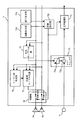
(第9の実施形態)
図17は、本発明の第9の実施形態に係るAV機器用音声認識装置の構成を示すブロック図である。図17の音声認識装置7は、図1のAV機器に設けられた音声認識装置7と対応している。ただし、本実施形態では、AV機器において、AV処理部3から2チャンネル信号が出力され、スピーカユニット9に含まれる2つのスピーカ9aおよび9bを通じて2チャンネル音響が出力されるものとする。
【0173】
図17において、音声認識装置7は、モノラル化部155と、1個のエコーキャンセラ153と、音声認識部154と、起動命令部1582と、終了命令部1583と、状態設定部1581と、切り替え部156と、適応制御部157とを備えている。すなわち、図17の音声認識装置7は、図16の音声認識装置7(第8の実施形態)と同様の構成を有する。図16の音声認識装置7との相違は、次の点である。すなわち、図1のAV処理部3からの音響信号は、2チャンネル(ステレオ)の場合と、モノラルの場合とがあり、図1のAV処理部3から適応制御部157へ、モノラル/ステレオ識別信号がさらに与えられる。スピーカ9aおよび9bへと入力される信号は、図1のAV処理部3から出力される2チャンネルまたはモノラル信号である。
【0174】
適応制御部157は、状態設定部1581の設定と、モノラル/ステレオ識別信号とに関連して、エコーキャンセラ153内の適応ディジタルフィルタ153aの適応速度を制御する。すなわち、ディジタルフィルタ153aは、入力信号への適応速度が可変であり、適応制御部157は、モノラル用の速い適応速度と、2チャンネル用の遅い適応速度とを予め記憶している。状態設定部1581の設定によって音声認識動作が”OFF”状態から”ON”状態へと移行する(それに伴い、スピーカ出力が2チャンネル音響からモノラル音響に切り替わる)のを受け、適応制御部157は、ディジタルフィルタ153aの適応速度を、遅い適応速度から速い適応速度に変更する。また、音声認識動作が”ON”状態から”OFF”状態へと移行するのを受け、ディジタルフィルタ153aの適応速度を、速い適応速度から遅い適応速度に変更する。
【0175】
ただし、適応制御部157は、モノラル/ステレオ識別信号がステレオを示している場合のみ、上記のような適応速度の変更を行い、モノラルを示す場合には、状態設定部1581の設定に関わらず、ディジタルフィルタ153aの適応速度を速い適応速度とする。
適応制御部157以外の構成要素の動作は、第8の実施形態と同様なので、説明を省略する。
【0176】
図17の音声認識装置7のハードウエア的な構成は、図3と同様である。図3において、ROM12に格納されているプログラムは、第8の実施形態と同様である。ただし、上記(m)のアルゴリズム、すなわちエコーキャンセラの適応速度を制御するためのアルゴリズムについては、音声認識動作の”ON”/”OFF”状態だけでなく、モノラル/ステレオ識別信号をも参照して制御を行うように変更が加えられている。CPU10は、RAM11を作業領域として利用しつつ、上記のプログラムに従って動作する。これによって、図17に示される各ブロックの機能が実現される。
【0177】
なお、起動命令部1582,終了命令部1583は、図1のコントローパネルを構成するボタンによって実現される。また、起動命令部1582,終了命令部1583以外の各ブロックの機能をソフト的に実現する代わりに、各々専用のハード回路によって実現することもできる。
【0178】
以上のように構成されたAV機器用音声認識装置7について、以下、その動作を述べる。
一般のTV放送においては、ステレオ番組とモノラル番組の2つの番組があり、ステレオ番組かモノラル番組かを識別する識別信号が、映像/音響信号とともに放送されている。受信側では、この識別信号により、現在の番組がステレオ番組かモノラル番組かを知ることができる。
先の図16の音声認識装置7では、現在受信しているのがステレオ番組かモノラル番組かを問わず、モノラル化部155で処理した信号がスピーカ9aおよび9bに入力されていない待機状態においては、エコーキャンセラ153の適応速度を落としていたが、待機状態であっても、適応速度を落としたくないのは当然である。
【0179】
適応速度を落とした状態では、エコーキャンセラ153が系の変動に追従できていない可能性があり、そのような時に動作状態に移行すると、十分なエコー打ち消し量が得られない。これに対して、待機状態であっても適応速度を落とさなければ、エコーキャンセラ153が常に系の変動に追従できているので、いつ動作状態に移行しても、十分なエコー打ち消し量が確保できるからである。
【0180】
放送そのものがモノラル番組であれば、モノラル化部155でモノラル化していない待機状態においても、適応速度を速めることが可能である。そこで、図17の音声認識装置7では、適応制御部157は、まず識別信号をチェックし、その結果、現在受信しているのがステレオ番組の場合、待機状態では、エコーキャンセラ153の適応速度を遅くするが、モノラル番組の場合、待機状態であっても動作状態と同様、適応速度を速いままに保つ。
【0181】
以上のように、本実施形態によれば、ステレオ/モノラル識別信号に基づいて、現在受信している番組の音声がステレオかモノラルかを判定して、モノラルの場合は、音声認識動作が待機状態であっても、エコーキャンセラ153の適応速度を遅くしないので、反響路のインパルスレスポンスの変動への追従性が低下することがなく、その結果、待機状態において優れたエコー打ち消し効果が実現でき、動作状態へ移行した直後における音声認識性能が高まる。
【0182】
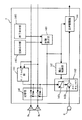
(第10の実施形態)
図18は、本発明の第10の実施形態に係るAV機器用音声認識装置の構成を示すブロック図である。図18の音声認識装置7は、図1のAV機器に設けられた音声認識装置7と対応している。ただし、本実施形態では、AV機器において、AV処理部3から2チャンネル信号が出力され、スピーカユニット9に含まれる2つのスピーカ9aおよび9bを通じて2チャンネル音響が出力されるものとする。
【0183】
図18において、音声認識装置7は、モノラル化部165と、1個のエコーキャンセラ163と、音声認識部164と、起動命令部1682と、終了命令部1683と、状態設定部1681と、切り替え部166と、モノラル度判定部1671と、適応制御部1672とを備えている。すなわち、図18の音声認識装置7は、図16の音声認識装置7(第8の実施形態)に、モノラル度判定部1671を追加したものである。モノラル度判定部1671は、図9のモノラル度判定部76(第4の実施形態を参照)と同じものである。スピーカ9aおよび9bへと入力される信号は、図1のAV処理部3から出力される2チャンネル信号である。
【0184】
モノラル度判定部1671へは、上記の2チャンネル信号が分岐入力され、モノラル度判定部1671は、その2チャンネル信号のモノラル度を判定する。適応制御部1672は、モノラル判定部の判定結果に関連して、エコーキャンセラ163内の適応ディジタルフィルタ163aの適応速度を制御する。
【0185】
すなわち、適応制御部1672は、2チャンネル信号のモノラル度に応じて、ディジタルフィルタ163aの適応速度を変化させる。好ましくは、モノラル度が高いほど、適応速度を速くする。そのために、適応制御部1672は、適応速度を速める処理をどの強度で行うべきかをモノラル度をもとに決定するための関数(処理強度決定特性;図19に参照番号104で示される)を記憶している。
モノラル度判定部1671および適応制御部1672以外の構成要素の動作は、第8の実施形態と同様なので、説明を省略する。
【0186】
図18の音声認識装置7のハードウエア的な構成は、図3と同様である。図3において、ROM12には、所定のプログラムが予め格納されている。このプログラムには、第1の実施形態で述べた(a)〜(c)のアルゴリズムと、第2の実施形態で述べた(e)のアルゴリズムと、第3の実施形態で述べた(f)のアルゴリズムと、第4の実施形態で述べた(g)のアルゴリズムと、第8の実施形態で述べた(m)のアルゴリズムとが記述されている。
【0187】
ただし、上記(m)のアルゴリズム、すなわちエコーキャンセラの適応速度を制御するためのアルゴリズムについては、音声認識動作の”ON”/”OFF”状態に基づいて制御を行う(第8の実施形態)のではなく、スピーカへの2チャンネル信号のモノラル度に基づいて制御を行うように変更が加えられている。CPU10は、RAM11を作業領域として利用しつつ、上記のプログラムに従って動作する。これによって、図18に示される各ブロックの機能が実現される。
【0188】
なお、起動命令部1682,終了命令部1683は、図1のコントローパネルを構成するボタンによって実現される。また、起動命令部1682,終了命令部1683以外の各ブロックの機能をソフト的に実現する代わりに、各々専用のハード回路によって実現することもできる。
【0189】
以上のように構成されたAV機器用音声認識装置7について、以下、その動作を述べる。
図18の音声認識装置7は、先の図7の音声認識装置7において、モノラル度の低い信号が入力された時に、エコーキャンセラ163の適応精度が劣化するという欠点を解決するものである。前述したように、エコーキャンセラ163の適応は、その出力が”0”になる方向に、推定インパルスレスポンスを逐次修正していくものであり、騒音のように、インパルスレスポンスをいかに修正しても消去できない信号がエコーキャンセラ163への入力信号に含まれている場合には、推定インパルスレスポンスにおいて誤差が生じ、この誤差がエコー打ち消し量を悪化させる。
【0190】
これと同じことが、ステレオ信号の反響音を、モノラル化信号で打ち消す場合に起きる。すなわち、ステレオ信号の反響音をモノラル化信号で打ち消す場合、原理的に、インパルスレスポンスをいかに修正しても打ち消せない成分が残る。
この打ち消せない成分(ステレオ成分)が多い場合、すなわち、モノラル度の低いステレオ信号の場合には、原理的に打ち消せない信号を打ち消そうとエコーキャンセラ163が適応動作を重ねるため、せっかく推定したインパルスレスポンスを大きく破壊することになる。
【0191】
そこで、図18の音声認識装置7では、AV処理部3からのステレオ信号を分析して、原理的にエコー打ち消しが精度よく行え適応動作に適した信号であるかどうかを判断し、適応動作に適すると判断された時に、エコーキャンセラ163に適応動作を行わせる。
【0192】
図18の音声認識装置7では、適応に適した信号か否かは、信号のモノラル度で判断している。前述したように、モノラル度の高い信号ほどエコー打ち消し効果が高く、インパルスレスポンスの推定がうまく行える。そこで、まず、モノラル度判定部1671がステレオ信号のモノラル度を求める。次に、適応制御部1672がこのモノラル度に応じて、エコーキャンセラ163の適応速度を制御する。
【0193】
図19は、図18の適応制御部1672が行う適応速度制御処理の特性を示す図である。図19において、特性191は、図18のスピーカ9aおよび9bへ向かうステレオ信号のモノラル度と、エコーキャンセラ163の適応速度との関係を示している。
図19からわかるように、適応制御部1672は、ステレオ信号のモノラル度が高く適応に適すると判断した場合には、適応速度を上げて常に最良の推定インパルスレスポンスを得られるようにする。一方、モノラル度が低く適応に適さないと判断した場合には、適応速度を下げて推定インパルスレスポンスの破壊を防止する。
【0194】
以上のように、本実施形態によれば、2チャンネル信号(ステレオ信号)のモノラル度に基づいて、適応ディジタルフィルタ163aの適応速度を制御するので、様々なモノラル度を持った2チャンネル信号に好適なエコー打ち消しを行うことができる。
すなわち、モノラル度が低い場合、適応速度を遅くして、耐雑音性を高める。
一方、モノラル度が高い場合、適応ディジタルフィルタ163aから見ると雑音であるステレオ成分が少ないので、耐雑音性はあまり必要でない。よって、適応速度を速くすることによって、反響路のインパルスレスポンスの変動への追従性を高めることができる。その結果、特にモノラル度が高い場合に、優れたエコー打ち消し効果が実現でき、動作状態へ移行した直後における音声認識性能が高まる。
【0195】
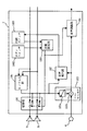
(第11の実施形態)
図20は、本発明の第11の実施形態に係るAV機器用音声認識装置の構成を示すブロック図である。図20の音声認識装置7は、図1のAV機器に設けられた音声認識装置7と対応している。ただし、本実施形態では、AV機器において、AV処理部3から2チャンネル信号が出力され、スピーカユニット9に含まれる2つのスピーカ9aおよび9bを通じて2チャンネル音響が出力されるものとする。
【0196】
図20において、音声認識装置7は、モノラル化部175と、1個のエコーキャンセラ173と、音声認識部174と、起動命令部1782と、終了命令部1783と、状態設定部1781と、切り替え部176と、不揮発メモリ177とを備えている。すなわち、図20の音声認識装置7は、図7の音声認識装置7(第3の実施形態)に、不揮発メモリ177を追加したものである。スピーカ9aおよび9bへと入力される信号は、図1のAV処理部3から出力される2チャンネル信号である。
【0197】
不揮発メモリ177へは、図1のコントロールパネル5からの電源”ON”/”OFF”信号が与えられ、不揮発メモリ177は、電源”OFF”時、エコーキャンセラ173が保持している推定インパルスレスポンスを取得し、それを記憶する。そして、電源”ON”時、記憶している推定インパルスレスポンスを、エコーキャンセラ173(内の適応ディジタルフィルタ173a)に与える。
エコーキャンセラ173は、反響音を打ち消す動作を開始する際に、この不揮発メモリ177から与えられた推定インパルスレスポンスを初期値として用いる。すなわち、適応ディジタルフィルタ173aは、不揮発メモリ177から与えられた値を初期値としてインパルスレスポンスの推定を開始する。
【0198】
エコーキャンセラ173は、電源”ON”時に用いる初期値の違いを除けば、図7のエコーキャンセラ54(第3の実施形態)と同様の動作を行う。なお、エコーキャンセラ54の場合、反響音を打ち消す動作を開始する際、”0”を初期値として用いるので、電源”ON”の直後から、ディジタルフィルタ54aの適応が進むまでの期間、反響音が十分に打ち消されない問題があった。
不揮発メモリ177およびエコーキャンセラ173以外の構成要素の動作は、第3の実施形態と同様なので、説明を省略する。
【0199】
図20の音声認識装置7のハードウエア的な構成は、図3において、さらに不揮発メモリ177を追加したものである。ROM12には、所定のプログラムが予め格納されている。このプログラムには、第1の実施形態で述べた(a)〜(c)のアルゴリズムと、第2の実施形態で述べた(e)のアルゴリズムと、第3の実施形態で述べた(f)のアルゴリズムとに加え、さらに(n)電源”OFF”時にエコーキャンセラ173が保持している推定インパルスレスポンスを不揮発メモリ177に書き込み、かつ電源”ON”時、その推定インパルスレスポンスをエコーキャンセラ173に与える手順が記述されている。CPU10は、RAM11を作業領域として利用しつつ、上記のプログラムに従って動作する。これによって、図20に示される各ブロックの機能が実現される。
【0200】
なお、起動命令部1782,終了命令部1783は、図1のコントローパネルを構成するボタンによって実現される。また、起動命令部1782,終了命令部1783以外の各ブロックの機能をソフト的に実現する代わりに、各々専用のハード回路によって実現することもできる。
【0201】
以上のように構成されたAV機器用音声認識装置7について、以下、その動作を述べる。
スピーカ9aおよび9bからマイクロホン6までの反響路のインパルスレスポンスは、壁、天井、床、家具、人、窓、カーテンなどでの音響の反射状態によって決まる。同じAV機器であっても、設置環境により千差万別のインパルスレスポンスが得られる。しかも、AV機器の移動、家具の移動、人の出入り、窓の開閉などにより時々刻々と変化する。固定したインパルスレスポンスでは、十分なエコー打ち消し効果が得られない。このため、図7の音声認識装置7のエコーキャンセラ173は、逐次適応を行っており、常に最新のインパルスレスポンスを推定している。しかし、インパルスレスポンスの初期値を”0”とした適応方法では、電源”ON”の直後に十分なエコー打ち消し量が得られないという欠点があった。
【0202】
人とか窓といった細かい変化を除けば、AV機器の設置位置や部屋形状などで決まる大まかなインパルスレスポンスは、部屋の家具の配置換えなどをしなければ、今日昨日で大きく変わるものではない。昨日の電源”OFF”時の推定インパルスレスポンスを、今日の電源”ON”時に使用しても、そこそこのエコー打ち消し量が得られる場合が多い。
【0203】
そこで、図20の音声認識装置7では、不揮発メモリ177を設け、電源”OFF”時にエコーキャンセラ173が保持していた推定インパルスレスポンスを不揮発メモリ177に記憶させ、電源”ON”時には、この不揮発メモリ177が記憶している推定インパルスレスポンスを初期値として、エコーキャンセラ173をスタートさせる。
【0204】
以上のように、本実施形態によれば、電源”OFF”時の推定インパルスレスポンスを記憶しておき、電源”ON”時、それを初期値としてインパルスレスポンスの推定を開始するので、”0”を初期値とする場合と比べ、電源”ON”直後の推定誤差が小さくなり、その結果、音声認識性能が高まる。
【0205】
(第12の実施形態)
図21は、本発明の第12の実施形態に係るAV機器用音声認識装置の構成を示すブロック図である。図21の音声認識装置7は、図1のAV機器に設けられた音声認識装置7と対応している。ただし、本実施形態では、AV機器において、AV処理部3から2チャンネル信号が出力され、スピーカユニット9に含まれる2つのスピーカ9aおよび9bを通じて2チャンネル音響が出力されるものとする。
【0206】
図21において、音声認識装置7は、モノラル化部185と、1個のエコーキャンセラ183と、音声認識部184と、音声検出部187と、起動命令部としてのボタンスイッチ1882と、終了命令部としての時限スイッチ1883と、状態設定部1881と、切り替え部186とを備えている。すなわち、図21の音声認識装置7は、図7の音声認識装置7(第3の実施形態)において、音声検出部187を追加し、さらに、起動命令部581を特にボタンスイッチ1882とし、かつ終了命令部582を特に時限スイッチ1883としたものである。音声検出部187は、図5の音声検出部37と同じものである(第2の実施形態を参照)。スピーカ9aおよび9bへと入力される信号は、図1のAV処理部3から出力される2チャンネル信号である。
【0207】
ボタンスイッチ1882が押されると、ボタンスイッチ1882から状態設定部1881へ、音声認識動作の起動を命令する信号が送られる。音声検出部187は、ユーザ音声の有無を検出して、検出結果を時限スイッチ1883に通知する。時限スイッチ1883は、ユーザの音声が有の状態から無の状態へ移行した瞬間を捉えて計時処理を開始する。そして、計時開始から予め決められた時間が経過すると、状態設定部1881へ、音声認識動作の終了を命令する信号を送る。
【0208】
状態設定部1881は、ボタンスイッチ1882,時限スイッチ1883からの命令信号を受け、音声認識部184の動作状態を設定(つまり音声認識動作を”ON”/”OFF”)する。
音声検出部187、ボタンスイッチ1882、時限スイッチ1883および状態設定部1881以外の構成要素の動作は、第3の実施形態と同様なので、説明を省略する。
【0209】
図21の音声認識装置7のハードウエア的な構成は、図3と同様である。図3において、ROM12には、所定のプログラムが予め格納されている。このプログラムには、第1の実施形態で述べた(a)〜(c)のアルゴリズムと、第2の実施形態で述べた(e)のアルゴリズムと、第3の実施形態で述べた(f)のアルゴリズムとに加え、さらに(o)計時を行い、かつ計時開始から予め決められた時間が経過すると終了命令信号を送信する手順が記述されている。CPU10は、RAM11を作業領域として利用しつつ、上記のプログラムに従って動作する。これによって、図21に示される各ブロックの機能が実現される。
【0210】
なお、ボタンスイッチ1882は、図1のコントローパネルを構成するいずれかのボタンによって実現される。また、ボタンスイッチ1882以外の各ブロックの機能をソフト的に実現する代わりに、各々専用のハード回路によって実現することもできる。
【0211】
以上のように構成されたAV機器用音声認識装置7について、以下、その動作を述べる。
本実施形態では、図7の音声認識装置7において、起動命令部581および終了命令部582の具体例を示している。ユーザは、音声認識機能を利用しようとする場合、まず、図7の起動命令部581に相当するボタンスイッチ1882を押す。すると、状態設定部1881に対して待機状態(音声認識動作が”OFF”の状態)から動作状態(”ON”状態)への切り替えの指示がなされ、かつ、時限スイッチ1883に対して時間計測開始の指示がなされる。
【0212】
動作状態においては、音声検出部187がユーザ音声が入力されたか否かをチェックし、音声が検出された時に、時限スイッチ1883は、計測時間をリセットする(つまり計測時間を0に戻す)。音声が検出されない状態が続き、時限スイッチ1883の計測時間が定められた値を超えた時、時限スイッチ1883は、状態設定部1881に動作状態から待機状態への切り替えを指示する。
【0213】
以上のように、本実施形態によれば、音声認識機能の終了を自動的に行えるようになる。
【0214】
(第13の実施形態)
図22は、本発明の第13の実施形態に係るAV機器用音声認識装置の構成を示すブロック図である。図22の音声認識装置7は、図1のAV機器に設けられた音声認識装置7と対応している。ただし、本実施形態では、AV機器において、AV処理部3から2チャンネル信号が出力され、スピーカユニット9に含まれる2つのスピーカ9aおよび9bを通じて2チャンネル音響が出力されるものとする。
【0215】
図22において、音声認識装置7は、モノラル化部195と、1個のエコーキャンセラ193と、音声認識部194と、音声検出部197と、起動命令部としての音声スイッチ1982と、終了命令部としての時限スイッチ1983と、状態設定部1981と、切り替え部196とを備えている。すなわち、図22の音声認識装置7は、図7の音声認識装置7(第3の実施形態)において、音声検出部197を追加し、さらに、起動命令部581を特に音声スイッチ1982とし、かつ終了命令部582を特に時限スイッチ1983としたものである。音声検出部197は、図5の音声検出部37と同じものである(第2の実施形態を参照)。スピーカ9aおよび9bへと入力される信号は、図1のAV処理部3から出力される2チャンネル信号である。
【0216】
音声検出部197は、ユーザ音声の有無を検出して、検出結果を音声スイッチ1982および時限スイッチ1983に通知する。音声スイッチ1982は、ユーザ音声が無から有に移行した瞬間を捉えて、状態設定部1981へ音声認識動作の起動を命令する信号を送る。時限スイッチ1983は、ユーザの音声が有の状態から無の状態へ移行した瞬間を捉えて計時処理を開始する。そして、計時開始から予め決められた時間が経過すると、状態設定部1981へ、音声認識動作の終了を命令する信号を送る。
【0217】
状態設定部1981は、音声スイッチ1982,時限スイッチ1983からの命令信号を受け、音声認識部194の動作状態を設定(つまり音声認識動作を”ON”/”OFF”)する。
音声検出部197、音声スイッチ1982、時限スイッチ1983および状態設定部1981以外の構成要素の動作は、第3の実施形態と同様なので、説明を省略する。
【0218】
図22の音声認識装置7のハードウエア的な構成は、図3と同様である。図3において、ROM12には、所定のプログラムが予め格納されている。このプログラムには、第1の実施形態で述べた(a)〜(c)のアルゴリズムと、第2の実施形態で述べた(e)のアルゴリズムと、第3の実施形態で述べた(f)のアルゴリズムと、第12の実施形態で述べた(o)の手順とに加え、さらに(p)音声が検出されると起動命令信号を送信する手順が記述されている。CPU10は、RAM11を作業領域として利用しつつ、上記のプログラムに従って動作する。これによって、図21に示される各ブロックの機能が実現される。
【0219】
なお、各ブロックの機能をソフト的に実現する代わりに、各々専用のハード回路によって実現することもできる。
【0220】
以上のように構成されたAV機器用音声認識装置7について、以下、その動作を述べる。
図22の音声認識装置7では、待機状態にあっても音声検出部197がユーザの音声の検出している。ユーザが音声認識機能を利用しようとする場合、まず、比較的大きな声を発する。音声検出部197がこの音声を検出し、検出結果を音声スイッチ1982に送る。検出結果があらかじめ設定したレベル以上の音声を検出したことを示す時、音声スイッチ1982は、音声認識の開始命令を状態設定部1981に送り、状態設定部1981に待機状態から動作状態への切り替えを指示する。
【0221】
音声検出部197による検出結果は、時限スイッチ1983へも送られ、応じて、時限スイッチ1983は、時間計測を開始する。動作状態においては、音声検出部197がユーザ音声が入力されたか否かをチェックし、音声が検出された時に、時限スイッチ1983は、計測時間をリセットする(つまり計測時間を0に戻す)。音声が検出されない状態が続き、時限スイッチ1983の計測時間が定められた値を超えた時、時限スイッチ1983は、状態設定部1981に動作状態から待機状態への切り替えを指示する。
【0222】
上記の音声スイッチ1982が”ON”となる音声レベルは、時限スイッチ1983がリセットされる音声レベルよりもかなり高く設定される。エコーキャンセラ193の打ち消し効果がよくない待機状態で発生する比較的大きなレベルの消し残しの反響音がユーザ音声として誤検出され、それに伴って動作モードに移行することがないようにするためである。
【0223】
以上のように、本実施形態によれば、音声認識機能の開始と終了を自動的に行えるようになる。
【図面の簡単な説明】
【図1】本発明が用いられるAV機器の構成の一例を示すブロック図である。
【図2】本発明の第1の実施形態に係るAV機器用音声認識装置の構成を示すブロック図である。
【図3】図1の音声認識装置7のハードウエア的な構成を示すブロック図である。
【図4】図2の音声認識装置7において、各構成要素に入力される、または各構成要素から出力される信号の時間波形を示す図である。
【図5】本発明の第2の実施形態に係るAV機器用音声認識装置の構成を示すブロック図である。
【図6】図5の音声認識装置7において、各構成要素に入力される、または各構成要素から出力される信号の時間波形を示す図である。
【図7】本発明の第3の実施形態に係るAV機器用音声認識装置の構成を示すブロック図である。
【図8】図7の音声認識装置7において、各構成要素に入力される、または各構成要素から出力される信号の時間波形を示す図である。
【図9】本発明の第4の実施形態に係るAV機器用音声認識装置の構成を示すブロック図である。
【図10】図9のモノラル度判定部76の詳細を示すブロック図である。
【図11】図9の任意度モノラル化部77の詳細を示すブロック図である。
【図12】図11の処理強度決定部91が行うモノラル化処理の強度、および図11の減衰器921〜924を通じて実現される利得(減衰量)を示す図である。
【図13】本発明の第5の実施形態に係るAV機器用音声認識装置の構成を示すブロック図である。
【図14】本発明の第6の実施形態に係るAV機器用音声認識装置の構成を示すブロック図である。
【図15】本発明の第7の実施形態に係るAV機器用音声認識装置の構成を示すブロック図である。
【図16】本発明の第8の実施形態に係るAV機器用音声認識装置の構成を示すブロック図である。
【図17】本発明の第9の実施形態に係るAV機器用音声認識装置の構成を示すブロック図である。
【図18】本発明の第10の実施形態に係るAV機器用音声認識装置の構成を示すブロック図である。
【図19】図18の適応制御部1672が行う適応速度制御処理の特性を示す図である。
【図20】本発明の第11の実施形態に係るAV機器用音声認識装置の構成を示すブロック図である。
【図21】本発明の第12の実施形態に係るAV機器用音声認識装置の構成を示すブロック図である。
【図22】本発明の第13の実施形態に係るAV機器用音声認識装置の構成を示すブロック図である。
【図23】従来のAV機器用音声認識装置の構成を示すブロック図である。
【図24】図23の音声認識装置において、各構成要素に入力される、または各構成要素から出力される信号の時間波形を示す図である。
【図25】別の従来のAV機器用音声認識装置の構成を示すブロック図である。
【符号の説明】
6…マイクロホン
7…AV機器用音声認識装置
9a〜9c…スピーカ
13,33他…モノラル化部
14,34他…エコーキャンセラ
14a,34a他…適応ディジタルフィルタ
14b,34b他…減算回路
15,35他…音声認識部
36,56他…切り替え部
37,117他…音声検出部
57,791他…状態設定部
581,792他…起動命令部
582,793他…終了命令部
75…完全モノラル化部
76,1671…モノラル度判定部
77…任意度モノラル化部
115…2チャンネル化部
126…適応音発生部
1373…減衰部
1371…打ち消し監視部
147,157,1672…適応制御部
177…不揮発メモリ
1882…ボタンスイッチ
1883,1983…時限スイッチ
1982…音声スイッチ[0001]
BACKGROUND OF THE INVENTION
The present invention relates to a speech recognition apparatus, and more specifically, is used in AV equipment such as a TV, a radio, an audio system, and the like that reproduces multi-channel audio including two-channel stereo, and is in a state where audio is amplified from a speaker. In particular, the present invention relates to a voice recognition device for AV equipment that can control AV equipment by voice, input information to the AV equipment by voice, and the like.
[Prior art]
Conventionally, Japanese Patent Laid-Open No. 5-22779 (invention name: “speech recognition remote control device”) is known as a document describing a technique for performing speech recognition in a state where audio is amplified from a speaker.
[0002]
FIG. 23 is a block diagram showing a configuration of a conventional AV equipment speech recognition apparatus using the technique disclosed in the above publication. The voice recognition apparatus shown in FIG. 23 is used for an AV device having one
[0003]
The operation of the conventional AV equipment speech recognition apparatus configured as described above will be described with reference to FIG.
FIG. 24 is a diagram illustrating a time waveform of a signal input to each component or output from each component in the speech recognition apparatus of FIG. In FIG. 24, a case where the user utters voice for voice control in a state where the audio signal is amplified from the
[0004]
When the user utters voice without the audio signal being loudened from the
[0005]
Therefore, the
[0006]
Therefore, in the speech recognition apparatus of FIG. 23, the
[0007]
A
[0008]
As can be seen by comparing the
[0009]
However, the speech recognition apparatus of FIG. 23 is compatible only with monaural audio AV equipment, and has a major drawback that it cannot be used with multi-channel audio AV equipment using a plurality of speakers. It was.
[0010]
FIG. 25 is a block diagram showing the configuration of another conventional audio equipment voice recognition apparatus. The voice recognition apparatus in FIG. 25 is used in a two-channel audio system AV device having two
In FIG. 25, another conventional speech recognition apparatus includes a
[0011]
In this conventional example, an echo sound that circulates from the
[0012]
However, since the speech recognition apparatus shown in FIG. 25 requires echo cancellers as many as the number of audio channels, it has a drawback that it becomes a very expensive speech recognition apparatus when used for AV equipment with multi-channel audio. It was.
Furthermore, in such a system using multiple echo cancellers, mutual interference between echo cancellers occurs, so that the adaptive operation of the echo canceller is extremely unstable, resulting in an increase in reverberation or oscillation due to adaptation failure. The major drawback was that it was known.
[0013]
[Problems to be solved by the invention]
In a voice recognition apparatus for AV equipment, it is strongly desired that voice recognition can be performed while reproducing audio through a speaker, that multi-channel audio can be supported, high reliability, and low cost.
[0014]
However, as described above, since the conventional speech recognition apparatus for AV equipment requires echo cancellers as many as the number of audio channels, there is a problem that the price is extremely high when used for multi-channel audio AV equipment. Had.
Another problem is that the adaptive operation of the echo canceller becomes extremely unstable due to mutual interference between the echo cancellers, resulting in an increase or oscillation of reverberation due to adaptation failure, resulting in a decrease in speech recognition performance. Also had.
[0015]
Therefore, an object of the present invention is to realize a voice recognition device for multi-channel AV equipment that can perform high-precision voice recognition in a state where multi-channel sound is output from a speaker and is inexpensive. is there.
[0016]
[Means for Solving the Problems and Effects of the Invention]
The first invention is used in an AV device that outputs multi-channel sound through a plurality of speakers, and recognizes a user voice input through a microphone, and causes the AV device to perform a predetermined processing operation. Because
Monaural means for monauralizing multi-channel signals going to multiple speakers,
The output of the microphone (hereinafter referred to as microphone output) and the output of the monauralization means (hereinafter referred to as monaural signal) are given, and the reverberation sound of the multi-channel sound is estimated based on the monaural signal, and the microphone output is One echo canceller to remove the reverberation,
Voice recognition means for recognizing user voice based on the output of one echo canceller (hereinafter, echo canceller output) is provided.
[0017]
In the first aspect of the invention, the multichannel signal is converted to monaural and supplied to one echo canceller, and the single echo canceller removes the reverberation sound of the multichannel sound from the microphone output, so that only one echo is used regardless of the number of channels. By simply providing a canceller, speech recognition can be performed while multi-channel sound is being output from the speaker. Further, unlike the case where a plurality of echo cancellers are provided, mutual interference between the echo cancellers does not occur and the voice recognition performance does not deteriorate.
[0018]
The second invention is characterized in that, in the first invention, a multi-channel signal is inputted to the plurality of speakers.
[0019]
In the second invention, since multi-channel sound is output from a plurality of speakers, the reverberant sound cannot be completely canceled with the monaural signal. However, if the monaural level of the multichannel signal is close to “1”, the reverberant sound can be almost canceled. As long as the monaural level of the multi-channel signal is not “0”, a part of the reverberant sound can be canceled.
Here, the monaural level of a multi-channel signal refers to the proportion of the component (mono component) that is included in the signal in common to all channels. If the signals of all channels are completely uncorrelated with each other, the monaural level The degree is “0”, and if they are the same, the monaural degree is “1”.
[0020]
According to a third invention, in the first invention, there is further provided switching means for inputting any of the multi-channel signal and the monaural signal to a plurality of speakers.
[0021]
In the third aspect of the invention, either multi-channel sound or monaural sound can be selectively output from a plurality of speakers.
[0022]
According to a fourth invention, in the third invention,
Voice detection means for detecting user voice based on the monaural signal and the echo canceller output;
Switching means
When no user voice is detected by the voice detection means, a multi-channel signal is input to a plurality of speakers,
When the user voice is detected by the voice detection means, the monaural signal is input to a plurality of speakers.
[0023]
In the fourth aspect of the invention, multi-channel sound is used when voice recognition is not required (user voice is not detected), and monaural sound is used when voice recognition is required (user voice is detected). Since it is output, speech recognition can be performed with sufficiently high accuracy.
[0024]
According to a fifth invention, in the third invention,
Start command means for commanding start of voice recognition operation;
An end instruction means for instructing the end of the voice recognition operation; and
In accordance with commands from the start command means and the end command means, further comprises state setting means for setting the voice recognition means to either the operating state or the standby state,
Switching means
When the voice recognition means is set to the standby state by the state setting means, multi-channel signals are input to a plurality of speakers,
When the voice recognition means is set to the operating state by the state setting means, the monaural signal is input to a plurality of speakers.
[0025]
In the fifth aspect of the invention, the multi-channel sound is output when the voice recognition means is in the standby state ("OFF" state), and the monaural sound is output when it is in the operating state ("ON" state). Voice recognition can be performed with high accuracy.
[0026]
According to a sixth invention, in the fifth invention,
Monaural degree judging means for judging the mono degree of the multi-channel signal, and
Further comprising arbitrary degree monaural means for monauralizing a multi-channel signal into an arbitrary monaural degree,
The monauralization means completely multi-channels the multichannel signal,
Arbitrary monauralization means is characterized in that, when the determination result of the monaural degree determination means is lower than a predetermined monaural degree, the multi-channel signal is monauralized to the predetermined monaural degree.
[0027]
In the sixth aspect of the invention, since the monaural level of the multi-channel signal is always greater than or equal to the predetermined monaural level, even when the voice recognition means is in the operating state ("ON" state), the stereoscopic effect is greatly impaired. Therefore, the speech recognition performance can be performed with high accuracy (that is, the stereoscopic effect and the speech recognition performance can be balanced).
[0028]
According to a seventh invention, in the fifth invention,
A multi-channel signal is a signal of 3 or more channels,
Further comprising two-channel converting means for converting a multi-channel signal into two channels;
The monaural unit converts the output of the two-channel unit (hereinafter referred to as a two-channel signal) to monaural,
The switching means is characterized in that any one of a multi-channel signal, a two-channel signal, and a monaural signal is input to a plurality of speakers.
[0029]
In the seventh aspect, multi-channel sound, 2-channel sound, and monaural sound can be selectively output from a plurality of speakers.
[0030]
In an eighth aspect based on the seventh aspect,
Voice detection means for detecting user voice based on the monaural signal and the echo canceller output;
Switching means
When the state setting means sets the voice recognition means to the standby state, multi-channel signals are input to a plurality of speakers,
When the state setting means sets the voice recognition means to the operating state, but no user voice is detected by the voice detection means, a two-channel signal is input to a plurality of speakers,
When a user voice is detected by the voice detection means, a monaural signal is input to a plurality of speakers.
[0031]
In the eighth aspect of the invention, when the voice recognition means is in the standby state ("OFF" state), multi-channel sound is used, and in the operating state ("ON" state), it is not necessary to perform voice recognition (the user voice is not If it is not detected, multi-channel sound is output, and if voice recognition needs to be performed (user's voice is detected), monaural sound is output, so that the stereoscopic effect in the standby state is sufficiently impaired without much loss. Voice recognition can be performed with high accuracy.
[0032]
According to a ninth invention, in the fifth invention,
Cancellation monitoring means for monitoring whether the echo sound is sufficiently canceled in the echo canceller based on the monaural signal and the echo canceller output,
Voice detection means for detecting user voice based on the monaural signal and the echo canceller output; and
Further comprising attenuation means for attenuating the multi-channel signal;
The attenuation means is characterized in that the multi-channel signal is attenuated when the voice detection means detects the user voice in a state where the monitoring result of the cancellation monitoring means indicates insufficient cancellation.
[0033]
In the ninth aspect, when user sound is detected in a state where the reverberant sound is not sufficiently canceled, mixing of reverberant sound is suppressed by lowering the level of sound output from the plurality of speakers. As a result, the speech recognition performance in a state where the reverberant sound is not sufficiently canceled is enhanced.
[0034]
A tenth aspect of the invention is the fifth aspect of the invention,
Echo canceller
An adaptive digital filter that estimates an impulse response of an echo path between a plurality of speakers and a microphone and calculates an echo sound from the estimated impulse response and the monaural signal; and
Subtracting means for subtracting the output of the adaptive digital filter from the microphone output is included.
[0035]
In the tenth aspect, multi-channel acoustic reverberation can be removed from the microphone output, and only the user voice can be given to the voice recognition means.
[0036]
According to an eleventh aspect, in the tenth aspect, when the input to the plurality of speakers is switched from the multichannel signal to the monaural signal by the switching means, the monaural adaptive sound for promoting the adaptation of the adaptive digital filter is obtained. An adaptive sound generating means is further provided.
[0037]
In the eleventh aspect of the invention, when the input to the speaker is switched from the multi-channel signal to the monaural signal, the monaural adaptive sound is output from the plurality of speakers. However, the impulse response held by the digital filter can be forcibly adapted to the impulse response of the echo path.
[0038]
In a twelfth aspect based on the tenth aspect,
Adaptive control means for controlling the adaptive speed of the adaptive digital filter,
The adaptive control means has a fast adaptation speed for mono and a slow adaptation speed for multi-channel, and when the state setting means sets the voice recognition means to the operating state, it selects the fast adaptation speed and enters the standby state. It is characterized by selecting a slow adaptation speed when setting.
[0039]
In the twelfth aspect of the invention, the adaptive speed of the adaptive digital filter in the echo canceller is controlled to a high speed when the voice recognition means is set to the operating state, and to a slow speed when the voice recognition means is set to the standby state. Echo cancellation suitable for monaural and multi-channel can be performed.
In other words, when multi-channel sound is output from the speaker, there are many stereo components that are noise when viewed from the adaptive digital filter. In this case, since there is no stereo component, it is possible to improve the followability to fluctuations in the impulse response of the echo path by setting a fast adaptation speed.
As a result, an excellent echo cancellation effect is realized in the standby state, and speech recognition performance immediately after the transition to the operation state is enhanced.
[0040]
In a thirteenth aspect based on the twelfth aspect,
The adaptive control means is provided with an identification signal indicating whether a signal input to a plurality of speakers is a multi-channel signal or a monaural signal,
The adaptive control means is characterized in that, when the identification signal indicates monaural, the fast setting speed is selected regardless of whether the state setting means sets the voice recognition means to the operating state or the standby state. .
[0041]
In the thirteenth aspect of the invention, the identification signal is used to determine whether the signals input to the plurality of speakers are multi-channel signals or monaural signals. If the signals are monaural signals, the state setting means sets the voice recognition means to the operating state. Regardless of whether it is set to the standby state or not, the fast adaptation speed is selected, so that the follow-up to fluctuations in the impulse response of the echo path is not reduced, resulting in excellent echo cancellation effect in the standby state. Is realized, and speech recognition performance immediately after shifting to the operating state is enhanced.
[0042]
In a fourteenth aspect based on the tenth aspect,
Monaural degree judging means for judging the mono degree of the multi-channel signal, and
Adaptive control means for controlling the adaptive speed of the adaptive digital filter based on the determination result of the monaural degree determination means is further provided.
[0043]
In the fourteenth aspect, since the adaptive speed of the adaptive digital filter is controlled based on the monaural level of the multichannel signal, echo cancellation suitable for the multichannel signal having various monaural levels can be performed.
That is, when the monaural level is low, the adaptation speed is slowed down to improve noise resistance.
On the other hand, when the monaural level is high, noise resistance is not so necessary because there are few stereo components as noise when viewed from the adaptive digital filter. Therefore, as in the fifteenth aspect of the invention, by increasing the adaptation speed, it is possible to improve the followability to fluctuations in the impulse response of the echo path. As a result, particularly when the monaural level is high, an excellent echo cancellation effect can be realized, and speech recognition performance immediately after shifting to the operating state is enhanced.
[0044]
According to a fifteenth aspect, in the fourteenth aspect, the adaptive control means increases the adaptation speed of the adaptive digital filter as the monaural level of the multichannel signal is higher.
[0045]
In a tenth aspect based on the tenth aspect,
A non-volatile memory,
Non-volatile memory
When the power is turned off, the impulse response estimated by the adaptive digital filter is acquired and stored,
When the power is turned “ON”, the estimated impulse response when the stored power is “OFF” is given to the adaptive digital filter,
The adaptive digital filter is characterized in that the estimation of the impulse response is started with the estimated impulse response at the time of power supply “OFF” given from the nonvolatile memory as an initial value.
[0046]
In the sixteenth aspect of the invention, the estimated impulse response when the power is “OFF” is stored, and when the power is “ON”, the impulse response is estimated using the initial value, so “0” is set as the initial value. Compared to the case, the estimation error immediately after the power “ON” is reduced, and as a result, the voice recognition performance is improved.
[0047]
In a seventeenth aspect based on the fifth aspect,
Voice detection means for detecting user voice based on the monaural signal and the echo canceller output;
The start command means is a button switch that issues a start command to the state setting means when the button is pressed,
The end instruction means is a time switch that issues an end instruction to the state setting means when the state in which the voice detection means does not detect the user voice continues for a predetermined time or longer.
[0048]
In the seventeenth aspect, the voice recognition operation can be automatically terminated.
[0049]
In an eighteenth aspect based on the fifth aspect,
Voice detection means for detecting user voice based on the monaural signal and the echo canceller output;
The activation command means is a voice switch that issues an activation command to the state setting means when the voice detection means detects a user voice.
The end instruction means is a time switch that issues an end instruction to the state setting means when the state in which the voice detection means does not detect the user voice continues for a predetermined time or longer.
[0050]
In the eighteenth aspect, the voice recognition operation can be automatically started and ended.
[0051]
DETAILED DESCRIPTION OF THE INVENTION
Hereinafter, embodiments of the present invention will be described with reference to the drawings.
First, an AV apparatus in which the present invention is used will be described.
FIG. 1 is a block diagram showing an example of the configuration of an AV device in which the present invention is used.
The AV device shown in FIG. 1 is a television receiver for receiving television broadcasting. In the television broadcasting here, it is assumed that a multi-channel (including two channels; the same applies hereinafter) sound system is employed.
[0052]
In FIG. 1, an AV device includes an antenna 1, a receiving unit 2, an AV processing unit 3, a
[0053]
The antenna 1 captures radio waves transmitted from broadcasting stations and converts them into electrical signals. The receiving unit 2 extracts a signal included in a specific frequency band from the electrical signal output from the antenna 1. The AV processing unit 3 processes the signal output from the receiving unit 2 and outputs a video signal and a multi-channel audio signal (hereinafter, multi-channel signal).
[0054]
The
[0055]
The control panel 5 (which may be provided on the receiver body or on the remote controller) is configured by buttons and the like, and generates a control signal corresponding to the button operation of the user. The
[0056]
Here, the signal output from the receiving unit 2 may be an analog signal or a digital signal. In the former case, the AV processing unit 3 is configured by a circuit that processes the signal output from the receiving unit 2 in an analog manner. In the latter case, the AV processing unit 3 is configured by a circuit that digitally processes a signal output from the receiving unit 2.
[0057]
In the television receiver configured as described above, the antenna 1 captures a radio wave transmitted from a broadcasting station and converts it into an electric signal, and the receiving unit 2 converts a signal in a specific frequency band from the electric signal. Extract. Next, the AV processing unit 3 processes the signal output from the receiving unit 2 and outputs a video signal and a multi-channel signal. The video signal output from the AV processing unit 3 is given to the
[0058]
The user can cause the television receiver to switch the reception channel by operating the
[0059]
In addition, the user can cause the television receiver to switch the reception channel by inputting sound through the
[0060]
In the above, a television receiver that outputs multi-channel sound has been described as an example of AV equipment to which the present invention is used. However, the present invention is not limited to a television receiver, and for example, outputs multi-channel sound. It may be used for a radio receiver. Alternatively, any device having a function of outputting multi-channel sound, such as a multi-channel audio system including a player, an amplifier, and a
[0061]
(First embodiment)
FIG. 2 is a block diagram showing the configuration of the audio equipment speech recognition apparatus according to the first embodiment of the present invention. The
[0062]
In FIG. 2, the
[0063]
A two-channel signal directed to the
A signal output from the microphone 6 (hereinafter referred to as a microphone output) and a signal output from the monauralization unit 13 (hereinafter referred to as a monaural signal) are provided to the
[0064]
Here, the operation principle of the
[0065]
A monaural signal is input to the adaptive
[0066]
The
[0067]
FIG. 3 is a block diagram showing a hardware configuration of the
This program includes (a) an algorithm for making a two-channel signal monaural, (b) an algorithm for removing an echo signal from the microphone output, and (c) for recognizing a user voice and generating a control signal. The algorithm is described. The
[0068]
The operation of the AV device
First, in the case where the left speaker input shown in 21 of FIG. 4 and the right speaker input shown in 22 of FIG. 4 are inputted to the
[0069]
The
[0070]
Next, the reason why a stereo signal (hereinafter, a two-channel signal is appropriately referred to as a stereo signal) can be canceled by one
If the transfer characteristic (impulse response) from the
[0071]
At this time, if the left and right transfer characteristics are approximately equal Hr≈Hl (≈H), then Se≈ (Sr + Sl) * H. If the left and right channel signals are approximately equal Sr≈Sl≈S, Se≈S * (Hr + Hl). Therefore, if either assumption is true, it can be seen that even one
[0072]
The greatest factors that determine the transfer characteristics Hr and Hl are the distance between the
[0073]
At high frequencies, the wavelength is short and phase inversion occurs due to a slight distance difference. Therefore, even if the distance is almost equal, the transfer characteristics including the phase are not sufficiently matched. However, since the transfer characteristics often agree fairly well at low and mid-range frequencies, the assumption of Hr≈H1 is established, and a certain amount of cancellation effect can be expected even with one
[0074]
Furthermore, when creating sound in actual TV programs, the center localization sound (monaural component) is mixed evenly on the left and right channels at a relatively high level, and this monaural component has a relatively localized sound (stereo component). Often mixed at a low level. That is, the center sound source is mainly made, and a substantial part of the left and right speaker inputs indicated by 21 and 22 is a monaural component.
In the case of such an audio signal mainly composed of the center sound source, the assumption of Sr≈S1 holds, and even a system using one
For the above reasons, it has been confirmed that a considerable echo canceling effect can be obtained even in the
[0075]
As described above, according to the present embodiment, since only one echo canceller can handle a stereo source (two-channel signal), an inexpensive AV device speech recognition apparatus can be realized. In addition, since only one echo canceller is used, there is no mutual interference between the echo cancellers, and an extremely important practical effect that a stable operation can be guaranteed is obtained.
[0076]
In the first embodiment (and the following second to fourth and sixth to thirteenth embodiments), in the AV device of FIG. 1, a two-channel signal is output from the AV processing unit 3, and two channels are output through the
In that case, the
[0077]
(Second Embodiment)
FIG. 5 is a block diagram showing the configuration of the audio equipment speech recognition apparatus according to the second embodiment of the present invention. The
[0078]
In FIG. 5, the
[0079]
A two-channel signal directed to the
A signal output from the microphone 6 (microphone output) and a signal output from the monaural unit 33 (monaural signal) are given to the
[0080]
The
[0081]
The
[0082]
The hardware configuration of the
[0083]
The operation of the AV device
First, as described in the first embodiment, the
[0084]
The
[0085]
In the
[0086]
6 shows an extracted echo signal included in the echo
[0087]
As described above, according to the present embodiment, it is possible to extract user sound with better S / N than the first embodiment by switching to monaural reproduction only when the user utters sound, usually in stereo reproduction. The recognition performance can be improved.
[0088]
(Third embodiment)
FIG. 7 is a block diagram showing a configuration of an AV equipment speech recognition apparatus according to the third embodiment of the present invention. The
[0089]
In FIG. 7, the
[0090]
A two-channel signal directed to the
A signal output from the microphone 6 (microphone output) and a signal output from the monaural unit 53 (monaural signal) are given to the
[0091]
The
[0092]
The
[0093]
The hardware configuration of the
[0094]
The
[0095]
The operation of the AV device
The
[0096]
In the operating state, the stereo feeling is impaired, but there is no major problem in listening to the audio signal. That is, in the operating state, the echo signal canceling effect is in the best state, and high-accuracy voice recognition can be expected. On the other hand, since the sense of stereo is impaired, the use of the voice recognition function is ended and the
[0097]
FIG. 8 is a diagram illustrating a time waveform of a signal input to or output from each component in the
[0098]
As described above, according to the present embodiment, user sound with a better S / N than the second embodiment is extracted by switching to monaural playback only when a voice recognition function is required, usually in stereo playback. And the recognition performance can be further improved.
[0099]
(Fourth embodiment)
FIG. 9 is a block diagram showing a configuration of a voice recognition apparatus for AV equipment according to the fourth embodiment of the present invention. The
[0100]
In FIG. 9, the
[0101]
A two-channel signal directed to the
Further, the two-channel signal directed to the
[0102]
That is, the arbitrary
[0103]
Here, the monaural level of the two-channel signal means the ratio of signal components (mono components) included in both channels in the signal, and the signals of both channels are completely uncorrelated with each other. , The monaural degree is “0”, and if they are the same, the monaural degree is “1”.
[0104]
A signal output from the microphone 6 (microphone output) and a signal output from the complete monaural unit 75 (complete monaural signal) are given to the
[0105]
The
[0106]
A signal output from the arbitrary monaural unit 77 (hereinafter referred to as an arbitrary monaural signal) and a two-channel signal from the AV processing unit 3 in FIG. 1 are provided to the
[0107]
The
[0108]
The hardware configuration of the
[0109]
The
[0110]
The operation of the AV device
In the
[0111]
Therefore, in this embodiment, the monaural signal is always input to the
[0112]
When the voice recognition function is to be used, first, similarly to the
[0113]
FIG. 10 shows details of the monaural
[0114]
In the case of a complete monaural signal, since Sr = Sl, the output of the
[0115]
As described above, the monaural
[0116]
FIG. 11 shows details of the
The output of the monaural
[0117]
FIG. 12 is a diagram illustrating the intensity of monaural processing performed by the processing
In FIG. 12A, a characteristic 101 indicates a relationship between the monaural level input to the processing
[0118]
In the present embodiment, the processing
[0119]
The processing
[0120]
According to the control method shown in FIG. 12, when the monaural processing intensity is “0”, the right channel signal is Sr and the left channel signal is S1, and the stereo signal from the AV processing unit 3 in FIG. Input to 9a and 9b. When the processing intensity is “1”, both channels are {(Sr + Sl) / 2}, and a completely monaural signal is input to the
[0121]
Even when the monaural level is limited in this way, in the speech recognition operation state, the stereo feeling of the audio signal is impaired although it is a short time. Therefore, at the same time when the use of the voice recognition function is terminated, a termination signal of the voice recognition function is sent from the
Thereby, it is possible to always obtain a sufficient amount of echo cancellation while ensuring a certain level of stereo feeling.
[0122]
As described above, according to the present embodiment, even in the operation state of the voice recognition function, a normal stereo signal is reproduced as it is, and monaural processing is performed only on a stereo signal having an extremely low monaural level. By adding, the echo cancellation effect is slightly lower than in the third embodiment, but the deterioration of stereo feeling can be suppressed to a much smaller level while always ensuring an echo cancellation amount of a certain level or higher.
[0123]
(Fifth embodiment)
FIG. 13: is a block diagram which shows the structure of the speech recognition apparatus for AV apparatuses which concerns on the 5th Embodiment of this invention. The
[0124]
In FIG. 13, the
[0125]
A four-channel signal directed to the
[0126]
A signal output from the microphone 6 (microphone output) and a signal output from the monaural unit 116 (monaural signal) are given to the
[0127]
The
The
[0128]
The signal output from the monaural unit 116 (monaural signal), the signal output from the 2-channel unit 115 (2-channel signal), and the 4-channel signal from the AV processing unit 3 in FIG. When the
[0129]
The
[0130]
The hardware configuration of the
[0131]
Note that the
[0132]
The operation of the AV device
In 4-channel stereo, sound creation characterized by 360 ° sound image localization is performed, so the correlation between channels is extremely weak. Therefore, when a 4-channel stereo signal is reproduced through the four
[0133]
However, if the 4-channel stereo signal is converted to a monaural signal at a stroke and listened to by the user, the dissatisfaction of the user due to the loss of stereo (stereoscopic) effect is extremely large. Therefore, in the present embodiment, in the voice recognition operation state, the 4-channel signal is converted into two channels so that the user can listen to the two-channel stereo sound, and only when the user utters voice in this operation state, the monaural operation is performed. Let the user hear the sound. Thereby, even in the operating state, a sufficient amount of echo cancellation can be secured while maintaining a reasonable stereo feeling.
[0134]
In FIG. 13, a two-channel signal is generated by the two-
A monaural signal is always input to the
[0135]
When the voice recognition function is to be used, first, a start signal for the voice recognition function is sent to the
[0136]
In the operating state, the
[0137]
As described above, according to the present embodiment, when the voice recognition function is not used, four-channel playback is performed, when the voice recognition function is activated, two-channel playback is performed, and when the voice is input, monaural playback is performed. By switching in steps, it is possible to ensure a reasonable stereo feeling even in the standby state, and to obtain a sufficient amount of echo cancellation.
[0138]
(Sixth embodiment)
FIG. 14 is a block diagram showing the configuration of the audio equipment speech recognition apparatus according to the sixth embodiment of the present invention. The
[0139]
In FIG. 14, the
[0140]
The
[0141]
The above-described adaptive sound has an effect of promoting the adaptive operation of the
[0142]
At this time, if a high level monaural sound is output from the
Since the operations of the components other than the
[0143]
The hardware configuration of the
[0144]
The
[0145]
The operation of the AV device
The
[0146]
In the
[0147]
Therefore, in the
As the adaptive sound, a synthetic voice such as “Please input voice” can be considered.
[0148]
As described above, according to the present embodiment, a monaural adaptive sound is output from the
[0149]
(Seventh embodiment)
FIG. 15 is a block diagram showing the configuration of the audio equipment speech recognition apparatus according to the seventh embodiment of the present invention. The
[0150]
In FIG. 15, the
[0151]
The
[0152]
The
[0153]
If the 2-channel signal is attenuated as described above, it is possible to prevent reverberation from being mixed into the
[0154]
At this time, if a high level monaural sound is output from the
Since the operations of the components other than the
[0155]
The hardware configuration of the
[0156]
The
[0157]
The operation of the AV device
The
[0158]
As described above, the
[0159]
Therefore, in the present embodiment, the
[0160]
As described above, according to the present embodiment, the user can cancel the echo cancellation amount immediately after the transition from the standby state (the voice recognition operation is “OFF”) to the operation state (“ON” state). When sound is emitted, this is detected and appropriate attenuation is inserted into the input signals to the
[0161]
(Eighth embodiment)
FIG. 16 is a block diagram showing the configuration of the audio equipment speech recognition apparatus according to the eighth embodiment of the present invention. The
[0162]
In FIG. 16, the
[0163]
The
Since the operations of the components other than the
[0164]
The hardware configuration of the
[0165]
The
[0166]
The operation of the AV device
As is well known, the adaptation of the
[0167]
In the successive correction of the estimated impulse response, the adaptive speed can be controlled by changing the correction amount per time. If the correction amount per time is large, the adaptation speed becomes fast, and if the correction amount is small, the adaptation speed becomes slow. When the adaptation speed is increased, the system is strong against fluctuations in the system (that is, it can quickly follow the impulse response fluctuations in the echo path), but is weak against noise (that is, the adaptive operation is likely to become unstable due to noise). Conversely, if the adaptation speed is slowed down, it becomes weak against fluctuations in the system but strong against noise. Therefore, in an actual apparatus, an adaptive speed that satisfies both the ability to follow system fluctuations and noise resistance is selected.
[0168]
In the
[0169]
Therefore, in the
That is, the
Specifically, the
[0170]
As described above, according to the present embodiment, the adaptive speed of the echo canceller 143 (internal adaptive
That is, when multi-channel sound is output from the
[0171]
Further, by changing the adaptive speed of the
[0172]
(Ninth embodiment)
FIG. 17 is a block diagram showing the configuration of the audio equipment speech recognition apparatus according to the ninth embodiment of the present invention. The
[0173]
In FIG. 17, the
[0174]
The
[0175]
However, the
Since the operations of the components other than the
[0176]
The hardware configuration of the
[0177]
The
[0178]
The operation of the AV device
In general TV broadcasting, there are two programs, a stereo program and a monaural program, and an identification signal for identifying whether the program is a stereo program or a monaural program is broadcast together with a video / audio signal. On the receiving side, it is possible to know from this identification signal whether the current program is a stereo program or a monaural program.
In the
[0179]
In a state where the adaptive speed is lowered, there is a possibility that the
[0180]
If the broadcast itself is a monaural program, the adaptation speed can be increased even in a standby state where the
[0181]
As described above, according to the present embodiment, it is determined whether the sound of the currently received program is stereo or monaural based on the stereo / monaural identification signal. Even so, since the adaptation speed of the
[0182]
(Tenth embodiment)
FIG. 18 is a block diagram showing the configuration of the audio equipment speech recognition apparatus according to the tenth embodiment of the present invention. The
[0183]
In FIG. 18, the
[0184]
The two-channel signal is branched and input to the monaural
[0185]
That is, the
Since the operations of the constituent elements other than the monaural
[0186]
The hardware configuration of the
[0187]
However, the algorithm (m), that is, the algorithm for controlling the adaptive speed of the echo canceller, is controlled based on the “ON” / “OFF” state of the speech recognition operation (eighth embodiment). Instead, a change is made to control based on the monaural level of the two-channel signal to the speaker. The
[0188]
The
[0189]
The operation of the AV device
The
[0190]
The same thing happens when the reverberation of a stereo signal is canceled with a monaural signal. That is, when canceling the echo sound of a stereo signal with a monaural signal, in principle, there remains a component that cannot be canceled no matter how the impulse response is modified.
In the case where there are many components (stereo components) that cannot be canceled, that is, in the case of a stereo signal with a low monaural level, the
[0191]
Therefore, the
[0192]
In the
[0193]
FIG. 19 is a diagram illustrating characteristics of adaptive speed control processing performed by the
As can be seen from FIG. 19, when it is determined that the monaural level of the stereo signal is high and suitable for adaptation, the
[0194]
As described above, according to the present embodiment, the adaptive speed of the adaptive
That is, when the monaural level is low, the adaptation speed is slowed down to improve noise resistance.
On the other hand, when the monaural level is high, noise resistance is not necessary because there are few stereo components as noise when viewed from the adaptive
[0195]
(Eleventh embodiment)
FIG. 20 is a block diagram showing the configuration of the audio equipment speech recognition apparatus according to the eleventh embodiment of the present invention. The
[0196]
In FIG. 20, the
[0197]
The power supply “ON” / “OFF” signal from the
The
[0198]
The
Since the operations of the components other than the
[0199]
The hardware configuration of the
[0200]
The
[0201]
The operation of the AV device
The impulse response of the reverberation path from the
[0202]
Except for subtle changes such as people and windows, the rough impulse response determined by the installation position and room shape of the AV equipment will not change significantly yesterday unless the furniture in the room is rearranged. Even if the estimated impulse response when the power is turned off yesterday is used when the power is turned on today, a decent amount of echo cancellation is often obtained.
[0203]
Therefore, in the
[0204]
As described above, according to the present embodiment, the estimated impulse response when the power is “OFF” is stored, and when the power is “ON”, the impulse response estimation is started with the initial value as “0”. Is smaller than the initial value, the estimation error immediately after the power is turned “ON” is reduced, and as a result, the speech recognition performance is improved.
[0205]
(Twelfth embodiment)
FIG. 21 is a block diagram showing the configuration of the audio equipment speech recognition apparatus according to the twelfth embodiment of the present invention. The
[0206]
In FIG. 21, the
[0207]
When
[0208]
The
Since the operations of the components other than the
[0209]
The hardware configuration of the
[0210]
The
[0211]
The operation of the AV device
In the present embodiment, specific examples of the
[0212]
In the operating state, the
[0213]
As described above, according to the present embodiment, the voice recognition function can be automatically terminated.
[0214]
(13th Embodiment)
FIG. 22 is a block diagram showing the configuration of the audio equipment speech recognition apparatus according to the thirteenth embodiment of the present invention. The
[0215]
In FIG. 22, the
[0216]
The
[0217]
The
Since the operations of the constituent elements other than the
[0218]
The hardware configuration of the
[0219]
Instead of realizing the function of each block in software, it can also be realized by a dedicated hardware circuit.
[0220]
The operation of the AV device
In the
[0221]
The detection result by the
[0222]
The sound level at which the
[0223]
As described above, according to the present embodiment, the voice recognition function can be automatically started and ended.
[Brief description of the drawings]
FIG. 1 is a block diagram showing an example of the configuration of an AV device in which the present invention is used.
FIG. 2 is a block diagram showing the configuration of the audio equipment speech recognition apparatus according to the first embodiment of the present invention.
FIG. 3 is a block diagram showing a hardware configuration of the
4 is a diagram illustrating a time waveform of a signal input to each component or output from each component in the
FIG. 5 is a block diagram showing a configuration of a speech recognition apparatus for AV equipment according to a second embodiment of the present invention.
6 is a diagram illustrating a time waveform of a signal input to each component or output from each component in the
FIG. 7 is a block diagram showing a configuration of a speech recognition apparatus for AV equipment according to a third embodiment of the present invention.
8 is a diagram illustrating a time waveform of a signal input to each component or output from each component in the
FIG. 9 is a block diagram showing a configuration of a speech recognition apparatus for AV equipment according to a fourth embodiment of the present invention.
10 is a block diagram illustrating details of the monaural
11 is a block diagram showing details of an
12 is a diagram illustrating the strength of monaural processing performed by the processing
FIG. 13 is a block diagram showing a configuration of a speech recognition apparatus for AV equipment according to a fifth embodiment of the present invention.
FIG. 14 is a block diagram showing a configuration of a speech recognition apparatus for AV equipment according to a sixth embodiment of the present invention.
FIG. 15 is a block diagram showing a configuration of an AV equipment speech recognition apparatus according to a seventh embodiment of the present invention.
FIG. 16 is a block diagram showing a configuration of a speech recognition apparatus for AV equipment according to an eighth embodiment of the present invention.
FIG. 17 is a block diagram showing a configuration of a speech recognition apparatus for AV equipment according to a ninth embodiment of the present invention.
FIG. 18 is a block diagram showing a configuration of a speech recognition apparatus for AV equipment according to a tenth embodiment of the present invention.
FIG. 19 is a diagram illustrating characteristics of adaptive speed control processing performed by the
FIG. 20 is a block diagram showing a configuration of a speech recognition apparatus for AV equipment according to an eleventh embodiment of the present invention.
FIG. 21 is a block diagram showing a configuration of a speech recognition apparatus for AV equipment according to a twelfth embodiment of the present invention.
FIG. 22 is a block diagram showing a configuration of a speech recognition apparatus for AV equipment according to a thirteenth embodiment of the present invention.
FIG. 23 is a block diagram showing a configuration of a conventional audio equipment voice recognition apparatus.
24 is a diagram illustrating a time waveform of a signal input to each component or output from each component in the speech recognition apparatus of FIG. 23. FIG.
FIG. 25 is a block diagram showing a configuration of another conventional AV device speech recognition apparatus.
[Explanation of symbols]
6 ... Microphone
7 ... Voice recognition device for AV equipment
9a-9c ... Speaker
13, 33, etc .. monaural unit
14, 34, etc ... Echo canceller
14a, 34a, etc .. Adaptive digital filter
14b, 34b, etc .... Subtraction circuit
15, 35, etc ... Voice recognition unit
36, 56, etc .... Switching section
37, 117, etc .... voice detector
57, 791, etc .. State setting section
581, 792 and others ... Start command section
582, 793, etc ... End command
75 ... Complete monophonic part
76, 1671 ... monaural degree determination unit
77 ... Arbitrary monaural unit
115 ... 2-channel section
126 ... Adaptive sound generator
1373: Attenuator
1371 ... Cancellation monitoring unit
147, 157, 1672 ... adaptive control unit
177 ... Non-volatile memory
1882 ... button switch
1883, 1983 ... Time switch
1982 ... Voice switch
Claims (14)
前記複数のスピーカへ向かうマルチチャンネル信号をモノラル化するモノラル化手段と、
前記マイクロホンの出力(以下、マイクロホン出力)と、前記モノラル化手段の出力(以下、モノラル化信号)とが与えられ、当該モノラル化信号に基づいて前記マルチチャンネル音響の反響音を推定して、当該マイクロホン出力から当該反響音を除去する1つのエコーキャンセラと、
前記1つのエコーキャンセラの出力(以下、エコーキャンセラ出力)に基づいて前記ユーザ音声を認識する音声認識手段と、
前記マルチチャンネル信号および前記モノラル化信号のいずれかを前記複数のスピーカへと入力するための切り替え手段と、
音声認識動作の起動を命令する起動命令手段と、
音声認識動作の終了を命令する終了命令手段と、
前記起動命令手段および前記終了命令手段からの命令に応じて、前記音声認識手段を動作状態および待機状態のいずれかに設定する状態設定手段とを備え、
前記切り替え手段は、
前記状態設定手段によって前記音声認識手段が待機状態に設定されている時、前記マルチチャンネル信号を前記複数のスピーカへと入力し、
前記状態設定手段によって前記音声認識手段が動作状態に設定されている時、前記モノラル化信号を前記複数のスピーカへと入力することを特徴とする、AV機器用音声認識装置。A voice recognition device that is used in an AV device that outputs multichannel sound through a plurality of speakers, recognizes a user voice input through a microphone, and causes the AV device to perform a predetermined processing operation.
A monaural means for monaural multichannel signal directed to said plurality of loudspeakers,
An output of the microphone (hereinafter referred to as a microphone output) and an output of the monauralization unit (hereinafter referred to as a monaural signal) are given, and the reverberation sound of the multi-channel sound is estimated based on the monaural signal, one and the echo canceller for removing the echo sound from the microphone output,
Voice recognition means for recognizing the user voice based on an output of the one echo canceller (hereinafter, echo canceller output) ;
Switching means for inputting any of the multi-channel signal and the monaural signal to the plurality of speakers;
Activation command means for commanding activation of speech recognition operation;
An end command means for commanding the end of the voice recognition operation;
State setting means for setting the voice recognition means to either an operating state or a standby state in response to a command from the start command means and the end command means ;
The switching means is
When the voice recognition unit is set to a standby state by the state setting unit, the multi-channel signal is input to the plurality of speakers,
A voice recognition apparatus for AV equipment , wherein the monaural signal is input to the plurality of speakers when the voice recognition means is set to an operating state by the state setting means .
前記マルチチャンネル信号を任意のモノラル度にモノラル化する任意度モノラル化手段とをさらに備え、
前記モノラル化手段は、前記マルチチャンネル信号を完全にモノラル化し、
前記任意度モノラル化手段は、前記モノラル度判定手段の判定結果が予め定められたモノラル度よりも低い場合、前記マルチチャンネル信号を当該予め定められたモノラル度にモノラル化することを特徴とする、請求項1に記載のAV機器用音声認識装置。Monaural level determination means for determining the monaural level of the multi-channel signal ;
Further comprising an optional degree monaural means for monaural any mono degree the multichannel signal,
The monauralization means completely monauralizes the multi-channel signal,
When the determination result of the monaural level determination unit is lower than the predetermined monaural level, the arbitrary degree monauralizing unit monarizes the multi-channel signal to the predetermined monaural level. The speech recognition apparatus for AV equipment according to claim 1 .
前記マルチチャンネル信号を2チャンネル化する2チャンネル化手段をさらに備え、
前記モノラル化手段は、前記2チャンネル化手段の出力(以下、2チャンネル化信号)をモノラル化し、
前記切り替え手段は、前記マルチチャンネル信号、前記2チャンネル化信号および前記モノラル化信号のいずれかを前記複数のスピーカへと入力することを特徴とする、請求項1に記載のAV機器用音声認識装置。The multi-channel signal is a signal of three or more channels,
Further comprising a two-channel unit for converting the multi-channel signal into two channels;
The monauralization means monarizes the output of the two-channelization means (hereinafter referred to as a two-channel signal),
2. The voice recognition apparatus for AV equipment according to claim 1 , wherein the switching unit inputs any one of the multi-channel signal, the two-channel signal, and the monaural signal to the plurality of speakers. .
前記切り替え手段は、
前記状態設定手段が前記音声認識手段を待機状態に設定している時には、前記マルチチャンネル信号を前記複数のスピーカへと入力し、
前記状態設定手段が前記音声認識手段を動作状態に設定しているが、前記音声検出手段によって前記ユーザ音声が検出されていない時には、前記2チャンネル化信号を前記複数のスピーカへと入力し、
前記音声検出手段によって前記ユーザ音声が検出されている時には、前記モノラル化信号を前記複数のスピーカへと入力することを特徴とする、請求項3に記載のAV機器用音声認識装置。Voice detection means for detecting the user voice based on the monaural signal and the echo canceller output;
The switching means is
When the state setting means sets the voice recognition means to the standby state, the multi-channel signal is input to the plurality of speakers,
When the state setting means sets the voice recognition means to an operating state, but the user voice is not detected by the voice detection means, the two-channel signal is input to the plurality of speakers,
The audio recognition apparatus for AV equipment according to claim 3 , wherein when the user voice is detected by the voice detection means, the monaural signal is inputted to the plurality of speakers.
前記モノラル化信号と前記エコーキャンセラ出力とに基づいて前記ユーザ音声を検出する音声検出手段と、
前記マルチチャンネル信号を減衰させる減衰手段とをさらに備え、
前記減衰手段は、前記打ち消し監視手段の監視結果が打ち消し不十分を示している状態において、前記音声検出手段がユーザ音声を検出した時、前記マルチチャンネル信号を減衰させることを特徴とする、請求項1に記載のAV機器用音声認識装置。On the basis of the monaural signal and the echo canceller output, and canceling monitoring means for monitoring whether the reverberation in the echo canceller is canceled sufficiently,
Voice detection means for detecting the user voice based on the monaural signal and the echo canceller output ;
Anda damping means for attenuating the multichannel signal,
The attenuation unit attenuates the multi-channel signal when the voice detection unit detects a user voice in a state where the monitoring result of the cancellation monitoring unit indicates insufficient cancellation. The speech recognition apparatus for AV equipment according to 1 .
前記複数のスピーカと前記マイクロホンとの間の反響路のインパルスレスポンスを推定して、当該推定インパルスレスポンスと、前記モノラル化信号とから前記反響音を算出する適応ディジタルフィルタと、
前記マイクロホン出力から、前記適応ディジタルフィルタの出力を減算する減算手段とを含む、請求項1に記載のAV機器用音声認識装置。The echo canceller is
An adaptive digital filter that estimates an impulse response of an echo path between the plurality of speakers and the microphone, and calculates the echo sound from the estimated impulse response and the monaural signal ;
Wherein the microphone output, the adaptive digital and a subtraction means for subtracting the output of the filter, the speech recognition apparatus for AV devices according to claim 1.
前記適応制御手段は、モノラル用の速い適応速度と、マルチチャンネル用の遅い適応速度とを持ち、前記状態設定手段が前記音声認識手段を動作状態に設定している時には速い適応速度を選択し、待機状態に設定している時には遅い適応速度を選択することを特徴とする、請求項6に記載のAV機器用音声認識装置。Adaptive control means for controlling the adaptive speed of the adaptive digital filter;
The adaptive control means has a fast adaptation speed for monaural and a slow adaptation speed for multi-channel, and selects the fast adaptation speed when the state setting means sets the voice recognition means to the operating state, The voice recognition apparatus for AV equipment according to claim 6 , wherein a slow adaptive speed is selected when the standby state is set.
前記適応制御手段は、前記識別信号がモノラルを示す場合、前記状態設定手段が前記音声認識手段を動作状態に設定しているか待機状態に設定しているかに関わらず、前記速い適応速度を選択することを特徴とする、請求項8に記載のAV機器用音声認識装置。The adaptive control means is provided with an identification signal indicating whether a signal input to the plurality of speakers is a multichannel signal or a monaural signal,
When the identification signal indicates monaural, the adaptive control means selects the fast adaptive speed regardless of whether the state setting means sets the voice recognition means to an operating state or a standby state. The voice recognition apparatus for AV equipment according to claim 8 , wherein:
前記モノラル度判定手段の判定結果に基づいて、前記適応ディジタルフィルタの適応速度を制御する適応制御手段とをさらに備える、請求項6に記載のAV機器用音声認識装置。Monaural level determination means for determining the monaural level of the multi-channel signal ;
On the basis of the determination result of the monaural level determination means, the adaptive digital further comprising an adaptive control means for controlling the adaptation speed of the filter, the speech recognition apparatus for AV equipment according to claim 6.
前記不揮発メモリは、
電源が"OFF"される時、前記適応ディジタルフィルタによって推定されたインパルスレスポンスを取得して記憶し、
電源が"ON"される時、記憶している電源"OFF"時の推定インパルスレスポンスを前記適応ディジタルフィルタに与え、
前記適応ディジタルフィルタは、前記不揮発メモリから与えられた電源"OFF"時の推定インパルスレスポンスを初期値として、インパルスレスポンスの推定を開始することを特徴とする、請求項6に記載のAV機器用音声認識装置。A non-volatile memory,
The nonvolatile memory is
When the power is turned off, the impulse response estimated by the adaptive digital filter is acquired and stored,
When the power is turned "ON", the estimated impulse response when the stored power is "OFF" is given to the adaptive digital filter,
The audio for AV apparatus according to claim 6 , wherein the adaptive digital filter starts an impulse response estimation using an estimated impulse response at the time of power supply "OFF" given from the nonvolatile memory as an initial value. Recognition device.
前記起動命令手段は、ボタンが押されると、前記状態設定手段へ起動命令を発するようなボタンスイッチであり、
前記終了命令手段は、前記音声検出手段がユーザ音声を検出しない状態が予め定められた時間以上継続すると、前記状態設定手段へ終了命令を発する時限スイッチであることを特徴とする、請求項1に記載のAV機器用音声認識装置。Voice detection means for detecting the user voice based on the monaural signal and the echo canceller output;
The activation command means is a button switch that issues an activation command to the state setting means when a button is pressed,
The end instruction means, said speech detection means when the state of not detecting a user's voice to continue a predetermined time or more, characterized in that it is a time switch which emits an end command to said state setting means, to claim 1 The voice recognition apparatus for AV apparatus as described.
前記起動命令手段は、前記音声検出手段がユーザ音声を検出すると、前記状態設定手段へ起動命令を発する音声スイッチであり、
前記終了命令手段は、前記音声検出手段がユーザ音声を検出しない状態が予め定められた時間以上継続すると、前記状態設定手段へ終了命令を発する時限スイッチであることを特徴とする、請求項1に記載のAV機器用音声認識装置。Voice detection means for detecting the user voice based on the monaural signal and the echo canceller output;
The activation command means is a voice switch that issues an activation command to the state setting means when the voice detection means detects a user voice,
The end instruction means, said speech detection means when the state of not detecting a user's voice to continue a predetermined time or more, characterized in that it is a time switch which emits an end command to said state setting means, to claim 1 The voice recognition apparatus for AV apparatus as described.
Priority Applications (1)
| Application Number | Priority Date | Filing Date | Title |
|---|---|---|---|
| JP2000227787A JP4554044B2 (en) | 1999-07-28 | 2000-07-27 | Voice recognition device for AV equipment |
Applications Claiming Priority (3)
| Application Number | Priority Date | Filing Date | Title |
|---|---|---|---|
| JP11-213276 | 1999-07-28 | ||
| JP21327699 | 1999-07-28 | ||
| JP2000227787A JP4554044B2 (en) | 1999-07-28 | 2000-07-27 | Voice recognition device for AV equipment |
Publications (3)
| Publication Number | Publication Date |
|---|---|
| JP2001100785A JP2001100785A (en) | 2001-04-13 |
| JP2001100785A5 JP2001100785A5 (en) | 2007-07-12 |
| JP4554044B2 true JP4554044B2 (en) | 2010-09-29 |
Family
ID=26519703
Family Applications (1)
| Application Number | Title | Priority Date | Filing Date |
|---|---|---|---|
| JP2000227787A Expired - Lifetime JP4554044B2 (en) | 1999-07-28 | 2000-07-27 | Voice recognition device for AV equipment |
Country Status (1)
| Country | Link |
|---|---|
| JP (1) | JP4554044B2 (en) |
Families Citing this family (19)
| Publication number | Priority date | Publication date | Assignee | Title |
|---|---|---|---|---|
| KR100552468B1 (en) * | 2001-07-19 | 2006-02-15 | 삼성전자주식회사 | an electronic-apparatus and method for preventing mis-operation and rising speech recognition rate according to sound recognizing |
| KR20040048435A (en) * | 2002-12-03 | 2004-06-10 | 조미화 | Voice-controlled television set and operating method thereof |
| NO319467B1 (en) * | 2003-12-29 | 2005-08-15 | Tandberg Telecom As | System and method for improved subjective stereo sound |
| JP4333369B2 (en) * | 2004-01-07 | 2009-09-16 | 株式会社デンソー | Noise removing device, voice recognition device, and car navigation device |
| KR100647286B1 (en) | 2004-08-14 | 2006-11-23 | 삼성전자주식회사 | Postprocessing apparatus and method for removing cross-channel interference and apparatus and method for separating multi-channel sources employing the same |
| NO328256B1 (en) * | 2004-12-29 | 2010-01-18 | Tandberg Telecom As | Audio System |
| JP4652116B2 (en) * | 2005-05-09 | 2011-03-16 | 三菱電機株式会社 | Echo canceller |
| US7769593B2 (en) | 2006-09-28 | 2010-08-03 | Sri International | Method and apparatus for active noise cancellation |
| CN102057428B (en) * | 2008-06-11 | 2013-08-14 | 三菱电机株式会社 | Echo canceller |
| JP5488478B2 (en) | 2011-01-18 | 2014-05-14 | オンキヨー株式会社 | Audio processing device |
| KR101590332B1 (en) | 2012-01-09 | 2016-02-18 | 삼성전자주식회사 | Imaging apparatus and controlling method thereof |
| KR101631594B1 (en) * | 2012-01-09 | 2016-06-24 | 삼성전자주식회사 | Display apparatus and controlling method thereof |
| WO2014103099A1 (en) * | 2012-12-28 | 2014-07-03 | パナソニック株式会社 | Device with voice recognition function and method for recognizing voice |
| WO2016024345A1 (en) | 2014-08-13 | 2016-02-18 | 三菱電機株式会社 | Echo canceler device |
| KR102306798B1 (en) | 2015-03-20 | 2021-09-30 | 삼성전자주식회사 | Method for cancelling echo and an electronic device thereof |
| DE102015222105A1 (en) | 2015-11-10 | 2017-05-11 | Volkswagen Aktiengesellschaft | Audio signal processing in a vehicle |
| JP6311784B2 (en) * | 2016-12-20 | 2018-04-18 | ソニー株式会社 | Television receiver, audio processing method, audio processing program, audio device, audio output method, and audio output program |
| CN108320755A (en) * | 2018-04-28 | 2018-07-24 | 子歌教育机器人(深圳)有限公司 | A kind of voice collecting circuit of robot |
| CN112420064B (en) * | 2020-10-21 | 2024-04-02 | 深圳创维-Rgb电子有限公司 | Voice echo cancellation processing method and device for wireless loudspeaker box equipment and intelligent terminal |
Citations (2)
| Publication number | Priority date | Publication date | Assignee | Title |
|---|---|---|---|---|
| JPH02244099A (en) * | 1989-03-16 | 1990-09-28 | Aisin Seiki Co Ltd | Voice signal processor |
| JPH0764598A (en) * | 1993-07-26 | 1995-03-10 | Philips Electron Nv | Audio-signal discrimination device and audio apparatus |
Family Cites Families (8)
| Publication number | Priority date | Publication date | Assignee | Title |
|---|---|---|---|---|
| JPS57208596A (en) * | 1981-06-18 | 1982-12-21 | Hitachi Ltd | Voice recognition circuit |
| JP2926679B2 (en) * | 1995-10-12 | 1999-07-28 | 三菱電機株式会社 | On-board audio equipment |
| JPH09218687A (en) * | 1996-02-14 | 1997-08-19 | Shinko Electric Co Ltd | Muffling device |
| JPH09326844A (en) * | 1996-06-03 | 1997-12-16 | Mitsubishi Electric Corp | Noise reduction speech device and noise reduction speech method |
| JP3624997B2 (en) * | 1996-07-19 | 2005-03-02 | 株式会社リコー | Voice recognition device |
| JPH10178324A (en) * | 1996-12-19 | 1998-06-30 | Matsushita Electric Ind Co Ltd | Voice control device |
| JPH10257583A (en) * | 1997-03-06 | 1998-09-25 | Asahi Chem Ind Co Ltd | Voice processing unit and its voice processing method |
| JPH1115490A (en) * | 1997-06-23 | 1999-01-22 | Hitachi Microcomput Syst Ltd | Microphone system and speech recognition system |
-
2000
- 2000-07-27 JP JP2000227787A patent/JP4554044B2/en not_active Expired - Lifetime
Patent Citations (2)
| Publication number | Priority date | Publication date | Assignee | Title |
|---|---|---|---|---|
| JPH02244099A (en) * | 1989-03-16 | 1990-09-28 | Aisin Seiki Co Ltd | Voice signal processor |
| JPH0764598A (en) * | 1993-07-26 | 1995-03-10 | Philips Electron Nv | Audio-signal discrimination device and audio apparatus |
Also Published As
| Publication number | Publication date |
|---|---|
| JP2001100785A (en) | 2001-04-13 |
Similar Documents
| Publication | Publication Date | Title |
|---|---|---|
| JP4554044B2 (en) | Voice recognition device for AV equipment | |
| US6665645B1 (en) | Speech recognition apparatus for AV equipment | |
| JP3306600B2 (en) | Automatic volume control | |
| US9264834B2 (en) | System for modifying an acoustic space with audio source content | |
| US8842851B2 (en) | Audio source localization system and method | |
| US5131032A (en) | Echo canceller and communication apparatus employing the same | |
| US8369531B2 (en) | Audio reproducing apparatus and method thereof | |
| US20150358756A1 (en) | An audio apparatus and method therefor | |
| RU2206174C2 (en) | Method and device for controlling sound reproduction volume | |
| JP2010164970A (en) | Audio system and output control method for the same | |
| JP2004514926A (en) | Control method of device provided with sound output means | |
| EP2252083B1 (en) | Signal processing apparatus | |
| EP1463379A2 (en) | Sound-field setting system | |
| JP2006148888A (en) | Method and apparatus to automatically set multi-channel speaker modes | |
| JP2961952B2 (en) | Music voice discrimination device | |
| US20010050995A1 (en) | Audio system | |
| JP2006196940A (en) | Sound image localization control apparatus | |
| JP2009159020A (en) | Signal processing apparatus, signal processing method, and program | |
| JPH07111527A (en) | Voice processing method and device using the processing method | |
| JP2014181988A (en) | Audio apparatus | |
| JP7105320B2 (en) | Speech Recognition Device, Speech Recognition Device Control Method, Content Playback Device, and Content Transmission/Reception System | |
| JPH03285500A (en) | Acoustic device | |
| JP2004304778A (en) | Sound field setting method, sound field setting program, and audio signal reproducing apparatus | |
| CN116547753A (en) | Machine learning assisted spatial noise estimation and suppression | |
| JP4138565B2 (en) | Multi-channel audio loss control apparatus, method, and multi-channel audio loss control program |
Legal Events
| Date | Code | Title | Description |
|---|---|---|---|
| A521 | Request for written amendment filed |
Free format text: JAPANESE INTERMEDIATE CODE: A523 Effective date: 20070525 |
|
| A621 | Written request for application examination |
Free format text: JAPANESE INTERMEDIATE CODE: A621 Effective date: 20070525 |
|
| A977 | Report on retrieval |
Free format text: JAPANESE INTERMEDIATE CODE: A971007 Effective date: 20100405 |
|
| A131 | Notification of reasons for refusal |
Free format text: JAPANESE INTERMEDIATE CODE: A131 Effective date: 20100412 |
|
| A521 | Request for written amendment filed |
Free format text: JAPANESE INTERMEDIATE CODE: A523 Effective date: 20100608 |
|
| TRDD | Decision of grant or rejection written | ||
| A01 | Written decision to grant a patent or to grant a registration (utility model) |
Free format text: JAPANESE INTERMEDIATE CODE: A01 Effective date: 20100623 |
|
| A01 | Written decision to grant a patent or to grant a registration (utility model) |
Free format text: JAPANESE INTERMEDIATE CODE: A01 |
|
| A61 | First payment of annual fees (during grant procedure) |
Free format text: JAPANESE INTERMEDIATE CODE: A61 Effective date: 20100714 |
|
| FPAY | Renewal fee payment (event date is renewal date of database) |
Free format text: PAYMENT UNTIL: 20130723 Year of fee payment: 3 |
|
| R150 | Certificate of patent or registration of utility model |
Ref document number: 4554044 Country of ref document: JP Free format text: JAPANESE INTERMEDIATE CODE: R150 Free format text: JAPANESE INTERMEDIATE CODE: R150 |
|
| S111 | Request for change of ownership or part of ownership |
Free format text: JAPANESE INTERMEDIATE CODE: R313113 |
|
| R350 | Written notification of registration of transfer |
Free format text: JAPANESE INTERMEDIATE CODE: R350 |
|
| R250 | Receipt of annual fees |
Free format text: JAPANESE INTERMEDIATE CODE: R250 |
|
| EXPY | Cancellation because of completion of term |