JP4551892B2 - Linear motion guidance unit - Google Patents
Linear motion guidance unit Download PDFInfo
- Publication number
- JP4551892B2 JP4551892B2 JP2006293645A JP2006293645A JP4551892B2 JP 4551892 B2 JP4551892 B2 JP 4551892B2 JP 2006293645 A JP2006293645 A JP 2006293645A JP 2006293645 A JP2006293645 A JP 2006293645A JP 4551892 B2 JP4551892 B2 JP 4551892B2
- Authority
- JP
- Japan
- Prior art keywords
- holding plate
- roller
- casing
- track
- guide
- Prior art date
- Legal status (The legal status is an assumption and is not a legal conclusion. Google has not performed a legal analysis and makes no representation as to the accuracy of the status listed.)
- Active
Links
- 238000003825 pressing Methods 0.000 claims description 11
- 230000000295 complement effect Effects 0.000 claims description 9
- 238000005096 rolling process Methods 0.000 description 32
- 238000003780 insertion Methods 0.000 description 5
- 230000037431 insertion Effects 0.000 description 5
- 238000004519 manufacturing process Methods 0.000 description 3
- 239000004065 semiconductor Substances 0.000 description 3
- 230000004308 accommodation Effects 0.000 description 2
- 210000000078 claw Anatomy 0.000 description 2
- 239000000314 lubricant Substances 0.000 description 2
- 238000012423 maintenance Methods 0.000 description 2
- 230000002093 peripheral effect Effects 0.000 description 2
- 238000005452 bending Methods 0.000 description 1
- 238000004891 communication Methods 0.000 description 1
- 239000004519 grease Substances 0.000 description 1
- 238000002347 injection Methods 0.000 description 1
- 239000007924 injection Substances 0.000 description 1
- 238000007689 inspection Methods 0.000 description 1
- 238000005259 measurement Methods 0.000 description 1
- 239000000203 mixture Substances 0.000 description 1
- 210000002445 nipple Anatomy 0.000 description 1
- 125000006850 spacer group Chemical group 0.000 description 1
- 238000003892 spreading Methods 0.000 description 1
- 238000012546 transfer Methods 0.000 description 1
Images


Classifications
-
- F—MECHANICAL ENGINEERING; LIGHTING; HEATING; WEAPONS; BLASTING
- F16—ENGINEERING ELEMENTS AND UNITS; GENERAL MEASURES FOR PRODUCING AND MAINTAINING EFFECTIVE FUNCTIONING OF MACHINES OR INSTALLATIONS; THERMAL INSULATION IN GENERAL
- F16C—SHAFTS; FLEXIBLE SHAFTS; ELEMENTS OR CRANKSHAFT MECHANISMS; ROTARY BODIES OTHER THAN GEARING ELEMENTS; BEARINGS
- F16C29/00—Bearings for parts moving only linearly
- F16C29/04—Ball or roller bearings
- F16C29/06—Ball or roller bearings in which the rolling bodies circulate partly without carrying load
- F16C29/0602—Details of the bearing body or carriage or parts thereof, e.g. methods for manufacturing or assembly
- F16C29/0604—Details of the bearing body or carriage or parts thereof, e.g. methods for manufacturing or assembly of the load bearing section
- F16C29/0607—Details of the bearing body or carriage or parts thereof, e.g. methods for manufacturing or assembly of the load bearing section of parts or members for retaining the rolling elements, i.e. members to prevent the rolling elements from falling out of the bearing body or carriage
-
- F—MECHANICAL ENGINEERING; LIGHTING; HEATING; WEAPONS; BLASTING
- F16—ENGINEERING ELEMENTS AND UNITS; GENERAL MEASURES FOR PRODUCING AND MAINTAINING EFFECTIVE FUNCTIONING OF MACHINES OR INSTALLATIONS; THERMAL INSULATION IN GENERAL
- F16C—SHAFTS; FLEXIBLE SHAFTS; ELEMENTS OR CRANKSHAFT MECHANISMS; ROTARY BODIES OTHER THAN GEARING ELEMENTS; BEARINGS
- F16C29/00—Bearings for parts moving only linearly
- F16C29/04—Ball or roller bearings
- F16C29/06—Ball or roller bearings in which the rolling bodies circulate partly without carrying load
- F16C29/0602—Details of the bearing body or carriage or parts thereof, e.g. methods for manufacturing or assembly
- F16C29/0609—Details of the bearing body or carriage or parts thereof, e.g. methods for manufacturing or assembly of the ends of the bearing body or carriage where the rolling elements change direction, e.g. end caps
-
- F—MECHANICAL ENGINEERING; LIGHTING; HEATING; WEAPONS; BLASTING
- F16—ENGINEERING ELEMENTS AND UNITS; GENERAL MEASURES FOR PRODUCING AND MAINTAINING EFFECTIVE FUNCTIONING OF MACHINES OR INSTALLATIONS; THERMAL INSULATION IN GENERAL
- F16C—SHAFTS; FLEXIBLE SHAFTS; ELEMENTS OR CRANKSHAFT MECHANISMS; ROTARY BODIES OTHER THAN GEARING ELEMENTS; BEARINGS
- F16C29/00—Bearings for parts moving only linearly
- F16C29/04—Ball or roller bearings
- F16C29/06—Ball or roller bearings in which the rolling bodies circulate partly without carrying load
- F16C29/0633—Ball or roller bearings in which the rolling bodies circulate partly without carrying load with a bearing body defining a U-shaped carriage, i.e. surrounding a guide rail or track on three sides
- F16C29/0635—Ball or roller bearings in which the rolling bodies circulate partly without carrying load with a bearing body defining a U-shaped carriage, i.e. surrounding a guide rail or track on three sides whereby the return paths are provided as bores in a main body of the U-shaped carriage, e.g. the main body of the U-shaped carriage is a single part with end caps provided at each end
- F16C29/065—Ball or roller bearings in which the rolling bodies circulate partly without carrying load with a bearing body defining a U-shaped carriage, i.e. surrounding a guide rail or track on three sides whereby the return paths are provided as bores in a main body of the U-shaped carriage, e.g. the main body of the U-shaped carriage is a single part with end caps provided at each end with rollers
-
- F—MECHANICAL ENGINEERING; LIGHTING; HEATING; WEAPONS; BLASTING
- F16—ENGINEERING ELEMENTS AND UNITS; GENERAL MEASURES FOR PRODUCING AND MAINTAINING EFFECTIVE FUNCTIONING OF MACHINES OR INSTALLATIONS; THERMAL INSULATION IN GENERAL
- F16C—SHAFTS; FLEXIBLE SHAFTS; ELEMENTS OR CRANKSHAFT MECHANISMS; ROTARY BODIES OTHER THAN GEARING ELEMENTS; BEARINGS
- F16C43/00—Assembling bearings
- F16C43/04—Assembling rolling-contact bearings
Landscapes
- Engineering & Computer Science (AREA)
- General Engineering & Computer Science (AREA)
- Mechanical Engineering (AREA)
- Bearings For Parts Moving Linearly (AREA)
Description
この発明は,例えば,長尺な軌道レール及び該軌道レール上を転動体であるローラを介して相対摺動するスライダから成る直動案内ユニットに関する。 The present invention relates to a linear motion guide unit comprising, for example, a long track rail and a slider that slides on the track rail via a roller as a rolling element.
従来,直動案内ユニットは,長尺の軌道レールに対してスライダが複数の転動体を介して摺動自在に構成されたものであり,近年,直動案内ユニットとしては,負荷容量が大きく,転動体が超小形でなるローラから成るものが求められている。直動案内ユニットは,半導体製造装置,工作機械,各種組立装置,搬送機械等の各種の装置の摺動部に組み込まれて使用され,各種の機械装置ヘの適用拡大が要望されている。直動案内ユニットは,特に,半導体製造装置,測定装置等に使用されるものでは,益々,超小形でなり,高速摺動,高剛性,高精度に適合するものが要望されている。直動案内ユニットにおいて,ローラは,軌道レールとスライダとの間に形成される軌道路及びスライダに設けたリターン路と方向転換路からなる循環路を無限循環するものである。 Conventionally, the linear motion guide unit is configured such that the slider is slidable on a long track rail via a plurality of rolling elements. In recent years, the linear motion guide unit has a large load capacity, There is a demand for a rolling element comprising a roller having a very small size. The linear motion guide unit is used by being incorporated in sliding parts of various devices such as a semiconductor manufacturing device, a machine tool, various assembling devices, and a transporting machine, and there is a demand for expanding application to various mechanical devices. In particular, linear motion guide units that are used in semiconductor manufacturing equipment, measuring equipment, and the like are becoming increasingly smaller and are required to be capable of high speed sliding, high rigidity, and high precision. In the linear motion guide unit, the roller circulates infinitely on a raceway formed between the track rail and the slider and a circulation path including a return path and a direction change path provided on the slider.
従来,直動転がり案内ユニットとして,円筒ころ即ちローラを保持する保持手段をスライダにワンタッチで確実に固定し,定格荷重をアップできるものが知られている。保持手段は,ローラを保持する保持板と該保持板に係合して保持板をスライダに支持する固定バンドとから構成され,保持板をケーシングにワンタッチで確実に且つ容易に固定することができるものである。上記直動転がり案内ユニットは,ケーシングの上側軌道面と下側軌道面上に配置されるローラの間に保持板を配置し,保持板の係合溝とエンドキャップに形成された係合溝に固定バンドの保持部を係止させ,エンドキャップに形成された係止穴に固定バンドの屈曲部の先端の係止爪を係合させ,これによって保持手段がスライダに組み込まれ,ローラが軌道レールとケーシングとで形成された軌道路で保持される(例えば,特許文献1参照)。 2. Description of the Related Art Conventionally, linear motion rolling guide units are known in which a cylindrical roller, that is, a holding means for holding a roller can be securely fixed to a slider with one touch to increase a rated load. The holding means includes a holding plate that holds the roller and a fixing band that engages with the holding plate and supports the holding plate to the slider, and can securely and easily fix the holding plate to the casing with one touch. Is. In the linear motion rolling guide unit, a holding plate is disposed between rollers disposed on the upper raceway surface and the lower raceway surface of the casing, and the engagement groove formed on the end cap and the engagement groove formed on the end cap are provided. The holding portion of the fixed band is locked, and the locking claw at the tip of the bent portion of the fixed band is engaged with the locking hole formed in the end cap, whereby the holding means is incorporated in the slider, and the roller is moved to the track rail. And a track formed by the casing (see, for example, Patent Document 1).
また,転がり案内装置として,軌道レール体と軌道レール体の継ぎ部でローラが落ち込むのを防止し,応力が集中するのを防止し,ローラがスムーズに軌道レールから軌道レール体に移動できるように構成したものが知られている。該転がり案内装置は,長手方向に沿ってローラ転走面を持つ軌道レールと,該軌道レールに相対移動自在に組み込まれた移動台と,無限循環路内を循環する複数のローラから構成され,軌道レールは複数本の軌道レール体が直列に連接された構造であり,互いに連なる軌道レール体どうしの継ぎ目がローラ転走面を転走するローラの回転軸に対して交差するように構成されているものである(例えば,特許文献2参照)。 In addition, the rolling guide device prevents the roller from dropping at the joint between the track rail body and the track rail body, prevents stress concentration, and allows the roller to move smoothly from the track rail to the track rail body. The composition is known. The rolling guide device is composed of a track rail having a roller rolling surface along the longitudinal direction, a moving base incorporated in the track rail so as to be relatively movable, and a plurality of rollers circulating in the infinite circulation path. The track rail has a structure in which a plurality of track rail bodies are connected in series, and the seam between the track rail bodies that are connected to each other intersects the rotation axis of the roller rolling on the roller rolling surface. (See, for example, Patent Document 2).
また,運動案内装置として,リテーナが通過すると抵抗になる段差の数を可及的に少なくすることができ,リテーナのスムーズな循環,ひいては転動体のスムーズな循環が得られるものが知られている。該運動案内装置は,軌道レールを相対移動する移動ブロックには,負荷ローラ転走部,それと平行なローラ逃げ通路,及び負荷ローラ転走部とローラ逃げ通路とを接続する一対の方向転換路から成るローラ循環路が設けられ,ローラがローラ循環路でローラリテーナで一連に回転摺動自在に保持される。ローラ循環路には,長手方向全長に渡って収容溝が形成され,収容溝にはローラリテーナの連結帯を案内する連結帯案内部を形成した案内レール部材が収容される(例えば,特許文献3参照)。
近年,直動案内ユニットは,益々超極小形に構成され,高速摺動,高剛性,高精度に適合するものが要望されており,各種装置への転動体がローラでなる極小形な直動案内ユニットの適用が課題になっている。即ち,直動案内ユニットに形成された循環路において,ローラの転走がスムーズであることが要求され,ローラが小形になれば,特に,方向転換路と軌道路の境界部において,ローラが循環路の境界の境目で支障なく,また,ローラが斜めの姿勢になることなく,姿勢良くスムーズに案内されることが要求されている。 In recent years, linear motion guide units are increasingly becoming ultra-miniature, and there is a demand for high-speed sliding, high rigidity, and high precision. The application of guidance units is a challenge. That is, in the circulation path formed in the linear motion guide unit, it is required that the roller rolls smoothly, and if the roller becomes small, the roller circulates particularly at the boundary between the direction change path and the track path. There is a demand for smooth guidance with good posture without any trouble at the boundary of the road, and without the roller having an oblique posture.
従来の直動案内ユニットにおいて,転動体として円筒ころ即ちローラを用いる場合に,ローラは,ボールを使用する場合に比較して,ローラの転走姿勢に傾きが無く,整然と案内されなければならない。また,上記直動転がり案内ユニットは,比較的に小形のローラタイプのものに適用されているが,更に,超小形のローラタイプのものについて,ローラが極小,例えば,ローラ直径が1mm程度のサイズになり,各部材であるエンドキャップ,ケーシング,保持板等を連結する連結部における循環路をローラが支障無く整然と滑らかに転走することが求められる。直動案内ユニットでは,転動体がボールに比較してローラの場合には,ローラの転動面を案内するだけでなく,ローラの端面を同時に的確に摺接案内し,ローラの姿勢を走行方向に対して傾くことなく整然と案内することが必要であり,極小なローラにあっては,連結部における僅かな段差でもローラの転走に支障が生じることから,更にローラを安定して滑らに案内しなければならないという課題があった。 In a conventional linear motion guide unit, when a cylindrical roller, that is, a roller is used as a rolling element, the roller must be guided in an orderly manner with no inclination in the rolling posture of the roller as compared with the case of using a ball. In addition, the linear motion rolling guide unit is applied to a relatively small roller type. However, the ultra-small roller type has a very small roller, for example, a roller diameter of about 1 mm. Therefore, it is required that the roller rolls in an orderly and smooth manner without any hindrance in the circulation path in the connecting portion for connecting the end cap, casing, holding plate and the like which are each member. In the linear motion guide unit, when the rolling element is a roller compared to a ball, not only the roller rolling surface is guided, but also the roller end surface is simultaneously and accurately slidably guided to change the roller posture in the traveling direction. In the case of an extremely small roller, even a slight level difference in the connecting part may cause a problem in the rolling of the roller, so that the roller can be guided more smoothly and smoothly. There was a problem that had to be done.
従来の直動案内ユニットは,例えば,図13に示すように,保持板13とエンドキャップ4の案内部29との連結部28では,ローラ5に対して連結部28での面取り35が大きなものになっており,面取り35にローラ5の角部が落ち込んで引っ掛かり易くなり,更に,落ち込んだローラ5がエンドキャップ4の薄肉でなる案内部29を変形させたり,損傷させてしまい,ローラ5のスムーズな転走に障害が発生していた。また,循環路における連結部28は,ケーシング3とエンドキャップ4とが合体するケーシング3の端面34の位置,即ち,エンドキャップ4の方向転換路30とケーシング3の軌道面12即ち軌道路20とが連結する位置に合致しているため,更に,ローラ5に姿勢悪化が起き易いものになっている状況にあり,各部材との連結部をローラ5が支障無く滑らかに転走することが求められていた。
For example, as shown in FIG. 13, the conventional linear motion guide unit has a
この発明の目的は,上記の課題を解決することであり,軌道レールの軌道面とスライダのケーシングの軌道面とで形成される軌道路にはローラを保持するための保持板が設けられ,エンドキャップに形成された方向転換路と軌道路とが連通状態に形成され,保持板とエンドキャップとの端面での連結面に段差無く連続させてローラの転走でローラが傾いたり,境目で落ち込んだりすることを防止し,ローラを安定してスムーズに転走させることができる直動案内ユニットを提供することである。 SUMMARY OF THE INVENTION An object of the present invention is to solve the above-mentioned problem, and a holding plate for holding a roller is provided on a track path formed by a track surface of a track rail and a track surface of a slider casing, and an end. The direction change path and track path formed in the cap are formed in a communicating state, and the roller is tilted by the rolling of the roller continuously with no step on the connecting surface at the end surface of the holding plate and the end cap, or falls at the boundary It is to provide a linear motion guide unit that can prevent rolling and can stably and smoothly roll a roller.
この発明は,長手方向に沿って第1軌道面が形成された軌道レール及び前記軌道レールに対して相対摺動自在なスライダから成り,前記スライダは,前記軌道レールの前記第1軌道面に対向する第2軌道面が形成され且つ前記第1と第2軌道面間に形成される軌道路に平行なリターン路が形成されたケーシング,前記ケーシングの両端面にそれぞれ取り付けられ且つ前記軌道路と前記リターン路とを連通する方向転換路が形成されたエンドキャップ,前記軌道路と前記リターン路と一対の前記方向転換路とで構成される循環路を転走する複数のローラ,前記ケーシングの長手方向に対向して前記軌道路に沿って延び且つ前記ローラを前記軌道路に保持する保持板,及び前記保持板を前記ケーシングに固定する固定バンドを有することから成る直動案内ユニットにおいて,
前記エンドキャップには前記方向転換路に連通して端面から突出して前記軌道路に延びる案内部が形成され,前記保持板の端面は,前記ローラの端面を案内するため前記案内部の端面に連結し且つ前記案内部の前記端面を摺動方向に覆って互いに相補的に合致して構成され,
前記保持板の前記端面と前記案内部の前記端面とは,摺動方向に傾いた互いに補完的な形状の斜面,段付き面,又は段付き斜面に形成され,
前記ケーシングには,前記保持板と前記案内部との係合凸部が係合する係合凹溝が前記軌道面に沿って形成され,
前記固定バンドと係合する前記保持板の両端部には,前記固定バンドにより押圧される凸部が形成され,
前記保持板は,前記固定バンドによる前記凸部への押圧によって前記保持板の前記端面が前記案内部の前記端面を押圧して密接すると共に前記ケーシングの前記係合凹溝に位置決め固定されることを特徴とする直動案内ユニットに関する。
The present invention comprises a track rail having a first track surface formed along a longitudinal direction and a slider that is slidable relative to the track rail, and the slider faces the first track surface of the track rail. A casing having a second raceway surface formed therein and a return path formed parallel to the raceway formed between the first and second raceway surfaces, and attached to both end faces of the casing, and the raceway and the An end cap formed with a direction change path that communicates with the return path, a plurality of rollers that roll on a circulation path constituted by the track path, the return path, and a pair of the direction change paths, and a longitudinal direction of the casing comprising holding plate for holding and said roller extends along the raceway to the trackway facing, and said holding plate from having a fixing band for fixing to said casing In the motion guide unit,
Wherein the end cap guiding section Ru extending in the trackway and projects from the end face communicates is formed in the direction changing passage, the end surface of the holding plate, the end face of the guide portion for guiding the end surfaces of the roller Connected to cover the end surface of the guide portion in the sliding direction and complementarily match each other ,
The end surface of the holding plate and the end surface of the guide portion are formed on a slope, a stepped surface, or a stepped slope having complementary shapes inclined in the sliding direction,
In the casing, an engagement groove is formed along the raceway surface to engage an engagement protrusion between the holding plate and the guide portion.
Convex parts pressed by the fixing band are formed at both ends of the holding plate that engages with the fixing band,
The holding plate is Rukoto is positioned and fixed to the engaging groove of the casing together with the end face of the holding plate by pressing to the convex portion by the fixing band is closely presses the end face of the guide portion It is related with the linear motion guide unit characterized by these.
また,前記固定バンドは中央部を凸状に反らした曲線状の押え部を備えており,前記固定バンドの両端の係止部を前記エンドキャップの係止凹部に係止して前記固定バンドを前記エンドキャップに固定した状態で,前記保持板は前記押え部と前記凸部とで摺動方向に3点押圧状態になって前記ケーシングに位置決め固定される。 In addition, the fixing band includes a curved presser portion having a central portion bent in a convex shape, and the locking portions at both ends of the fixing band are locked to the locking recesses of the end cap so that the fixing band is In a state of being fixed to the end cap, the holding plate is positioned and fixed to the casing in a three-point pressing state in the sliding direction by the pressing portion and the convex portion.
また,この直動案内ユニットにおいて,前記循環路は前記スライダの幅方向両側に一対ずつ形成され,前記保持板は前記循環路間にそれぞれ配設されて前記循環路に組み込まれた前記ローラのそれぞれの端面を前記軌道路にて案内する案内面を備えている。 Further, in this linear motion guide unit, a pair of the circulation paths are formed on both sides in the width direction of the slider, and the holding plates are respectively disposed between the circulation paths and each of the rollers incorporated in the circulation path. Is provided with a guide surface for guiding the end face of the track along the track.
この直動案内ユニットは,上記のように,軌道路を転走するローラを保持する保持板の端面がエンドキャップの端面から突出した案内部の端面を摺動方向に覆うように斜面,段付き面,段付き斜面に構成されているので,保持板と案内部との互いに当接する端面の境界部で,段差が発生するのを防止でき,軌道路から方向転換路へ又は方向転換路から軌道路へのローラの転走が境界部で段差部に落ち込んだり引っかかったりすることが無くなり,ローラが循環路を安定して整然とスムーズに転走することができる。 As described above, this linear motion guide unit is inclined and stepped so that the end surface of the holding plate that holds the roller rolling on the raceway covers the end surface of the guide portion protruding from the end surface of the end cap in the sliding direction. Since it is composed of a surface and a stepped slope, it is possible to prevent the occurrence of a step at the boundary between the end surfaces of the holding plate and the guide portion that are in contact with each other. Rolling of the roller to the road does not fall or get caught in the stepped portion at the boundary portion, and the roller can stably and smoothly roll on the circulation path.
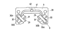
この直動案内ユニットは,図1及び図2に示すように,転動体としてローラ5が使用されるタイプに適用されて最適なものであり,長手方向の両側面47に沿って延びる一対の軌道面11(第1軌道面)をそれぞれ備えた長尺な軌道レール1,軌道レール1の長手方向に摺動自在なスライダ2,及び軌道レール1とスライダ2との間に形成された軌道路20及びスライダ2に設けられたリターン路10と方向転換路30から成る循環路を転走するローラ5を有している。スライダ2は,軌道レール1の軌道面11に対向して軌道面12(第2軌道面)が形成されたケーシング3,及びケーシング3の両端面34に配設されて上下の軌道路20と上下のリターン路10とを連通する方向転換路30が形成されたエンドキャップ4を有している。この直動案内ユニットは,軌道レール1の軌道面11とケーシング3の軌道面12との間には負荷軌道路となる軌道路20が形成され,軌道路20は,ケーシング3の袖部50に二条列ずつ合計で4列形成されている。ローラ5は,転動面48とその両端の端面49から成り,軌道路20においてケーシング3とエンドキャップ4とに取り付けられた保持板13によってローラ5の端面49が保持され,軌道路20をそれぞれ転動する。また,この直動案内ユニットは,ケーシング3とエンドキャップ4との下面に下面シール14が配置され,エンドキャップ4の端面42にリップ部16を備えたエンドシール15が接して配置され,シール構造に形成されている。また,軌道レール1には,各種の機器,ワーク,取付体,機台等のベースに軌道レール1を固定するため,取付け用孔17が形成されている。ケーシング3には,各種の機器,ワーク,取付体等の物体を取り付けため取付け用ねじ孔18が設けられている。
As shown in FIGS. 1 and 2, this linear motion guide unit is optimally applied to a type in which the
また,エンドキャップ4は,図1,図10及び図11に示すように,ケーシング3に対して位置決めされ,エンドキャップ4の取付け孔39に通じてボルト51でケーシング3のねじ穴22に固定されている。エンドキャップ4は,潤滑剤を供給するための給油口40及び給油溝41を備えており,エンドシール15が給油口40に対応して給油口43を備えている。この直動案内ユニットは,エンドシール15には,グリースニップルを配設するほどのスペースが無いために,代わりに注射針が通るような極小な口径(Φ=0.5mm以下)でなる給油口43が設けられている。この直動案内ユニットは,給油口43,40及び給油溝41を通じて循環路に潤滑剤が供給される。また,エンドキャップ4に形成された方向転換路30の入口部には,エンドキャップ4の背面の端面から突出する案内部29が形成されている。エンドキャップ4の案内部29は,方向転換路30から軌道路20側へ延びた態様になっている。また,ケーシング3の嵌挿孔9には,リターン路10を形成するパイプ6が嵌挿されている。パイプ6は,ケーシング3の両側に位置するエンドキャップ4によってケーシング3の嵌挿孔9に固定されるように構成されており,それによって,リターン路10と方向転換路30との断面矩形状の循環路が段差無くスムーズに接続され,ローラ5は方向転換路30からリターン路10ヘ,及びリターン路10から方向転換路30へ循環する上でスムーズに循環することができるように構成されている。パイプ6は,例えば,ケーシング3の嵌挿孔9に手動でスムーズに嵌入される。ここでは,パイプ6は,嵌挿孔9に若干のすきま嵌めされている。従って,パイプ6は,ケーシング3の嵌挿孔9には固定されておらずに遊嵌状態であり,ケーシング3の両端に配置されたエンドキャップ4によってスライダ2に固定状態に取り付けられている。
The
図2に示すように,スライダ2の両袖部には,それぞれ一対の循環路が形成され,一対の循環路の内,一方の循環路を転動するローラ5は,スライダ2の下方向負荷を受ける下側の軌道路20(F1)からケーシング3の上側のリターン路10(R1)に循環し,他方の循環路を転動するローラ5は,スライダ2の上方向負荷を受ける上側の軌道路20(F2)からケーシング3の下側のリターン路10(R2)に循環して構成されており,方向転換路30は,エンドキャップ4の両袖部にたすき掛けに交差状態にそれぞれ形成されている。例えば,図2に示すケーシング3の右側袖部50に想像線で示す方向転換路30では,軌道路20(F1)とリターン路10(R1)との方向転換路30が外側方向転換路30Bに形成され,また,軌道路20(F2)とリターン路10(R2)との方向転換路30が内側方向転換路30Aに形成されている。即ち,この直動案内ユニットは,軌道面11と軌道面12と間に形成された軌道路20をローラ5が転走し,上側の軌道路20のローラ5が下側のリターン路10へ循環し,下側の軌道路20のローラ5が上側のリターン路10へ循環して,スライダ2が軌道レール1に沿って相対摺動自在になっている。この直動案内ユニットは,転動体がローラ5でなる極小形のものであり,軌道路20のローラ5は,保持板13によって保持され,スライダ2を軌道レール1から外した場合に,スライダ2からローラ5が脱落することが無いものになっており,保持板13は,固定バンド7によりケーシング3の軌道路20に保持されるものであり,固定バンド7の両端の係止部24がエンドキャップ4のバンド溝26に嵌入係止することによって,スライダ2に固着されている。
As shown in FIG. 2, a pair of circulation paths is formed on both sleeve portions of the
この直動案内ユニットは,特に,ローラ5を保持する保持板13を固定バンド7でケーシング3に固定するタイプであり,更に,保持板13とエンドキャップ4との連結構成に特徴があり,極小なローラ5であっても安定して滑らかに循環路を転走できるものになっている。従来の直動案内ユニットでは,極小なローラの循環にあっては,従来の各部品の連結構成では,ローラに対する連結の食い違い,即ち段差が大きなものになってしまい,段差を小さくしようとすれば,各部品の精度を更に高精度に仕上げなければならなくなり,高価なものになってしまうという問題があった。この直動案内ユニットは,上記の構成において,ケーシング3の長手方向に対向して軌道路20に沿って延び且つローラ5を軌道路20に保持する保持板13,及び保持板13をケーシング3に固定する固定バンド7を有しており,特に,保持板13は,ローラ5の端面49を案内するため方向転換路30から連通して延びて,エンドキャップ4の背面側の端面から突出した案内部29に連結し,保持板13の端面は,エンドキャップ4の案内部29の端面を摺動方向に覆う状態に互いに相補的に合致して連結していることを特徴とする。即ち,この直動案内ユニットは,特に,軌道路20においてローラ5を案内する保持板13とエンドキャップ4の案内部29とが連結保持されたタイプに構成され,特に,転動体であるローラ5の直径が極小のものが組み込まれた極小形なローラタイプであって,超極小なローラ5にあっても安定して整然とスムーズに循環路を転走できるように構成されている。具体的には,この直動案内ユニットは,軌道レール1の幅が10mm程度であり,ローラ5の直径が1mm程度に形成された超小形のローラタイプに構成されている。
This linear motion guide unit is of a type in which the holding
また,この直動案内ユニットは,図5の(b)に一実施例が示されるように,保持板13と案内部29との連結部28が保持板13と案内部29との端面が互いに密接して当接し,保持板13と案内部29との端面は摺動方向に覆う状態に互いに相補的な形状,即ち,補完的な形状の斜面36に形成されている。即ち,保持板13は,エンドキャップ4の端面から突出して形成された案内部29に連結し,保持板13の端面が案内部29の端面を外側から覆う形に互いの端面が相補的即ち補完的形状に形成されたものになっており,この実施例では,互いに斜面36に形成されている。勿論,連結部28の形状は,端面が斜面36に限らず,例えば,図12の(a)に示すように,保持板13と案内部29との連結部28は,保持板13と案内部29との端面が互いに密接して当接し,保持板13と案内部29との端面は互いに補完的な形状の段付き面45に形成することができる。或いは,図12の(b)に示すように,保持板13と案内部29との連結部28は,保持板13と案内部29との端面が互いに密接して当接し,保持板13と案内部29との端面は互いに補完的な形状の段付き斜面46に形成することができる。
Further, in this linear motion guide unit, as shown in FIG. 5B, the connecting
この直動案内ユニットにおいて,図2に示すように,軌道路20においてケーシング3の軌道面12をローラ5が転動するのに伴ってローラ5の一方の端面49が保持板13の案内面33で案内され,また,ローラ5の他方の端面がケーシング3の凹部52の内壁面53で案内され,従って,ローラ5は保持板13の案内面33とケーシング3の内壁面53とで共働して案内保持されている。保持板13は,ローラ5の端面49を案内するための案内面33が形成されている。案内面33は,エンドキャップ4における方向転換路30のローラ5の端面49を案内する案内面(図示せず)に連通するように構成されている。保持板13は,軌道路20(F1)のローラ5の一方の端面49を案内する軌道路20に沿って形成された案内面33と,軌道路20(F2)のローラ5の一方の端面49を案内する軌道路20に沿って形成された案内面33とを有しており,図5の(a)に示すように断面方向に見て,互いの案内面33は直交する面に形成され,保持板13の断面は案内面33が形成された面を一対の辺とした二等辺三角形に形成されている。従って,保持板13は,一対の循環路のそれぞれのローラ5を同時に保持し,且つそれぞれのローラ5の一方の端面49を案内する案内面33がそれぞれに形成されたものになっている。保持板13は,スライダ2の軌道路20間にそれぞれ配設され,循環路に組み込まれたローラ5のそれぞれの端面49を,軌道路20において案内面33で案内保持するように構成されている。また,保持板13は,案内面33が形成されていない背面に固定バンド7を係合する凹溝でなるバンド構31が形成されている。この直動案内ユニットは,ケーシング3には,保持板13とエンドキャップ4の案内部29との係合凸部19が係合する係合凹溝21が軌道面12に沿って形成されている。保持板13は,保持板13の二等辺の凸部でなる先端部分である係合凸部19がケーシング3の一対の軌道面12間に形成されたV字状の凹構でなる係合凹溝21に嵌着して固定されるものになっている。
In this linear motion guide unit, as shown in FIG. 2, as the
また,保持板13は,保持板13の端面がエンドキャップ4の案内部29の端面を外側から覆う形に形成されることによって,スライダ2への組み立て時に,エンドキャツプ4をケーシング3に組み立てて,軌道路20側からローラ5を循環路に組み込んだ後に,保持板13をエンドキャップ4の案内部29の外側から覆い被せるようにしてケーシング3の係合凹溝21に嵌着可能になっている。図5(b)に示すように,保持板13とエンドキャップ4の案内部29との連結部28の案内面33は,ローラ5の進行方向即ち転走方向に対して直交しておらず,特に,実施例のように,連結部28の当接端面が斜面36に形成されているので,ローラ5の端面49が徐々に乗り移るようになって極小なローラ5にあっても多少の段差でも乗り移ることが可能となり,ローラ5が滑らかに案内される。更に,保持板13がエンドキャップ4の端面から突出して形成された案内部29に連結する。連結部28は,ケーシング3とエンドキャップ4とが合致するケーシング3の端面34の位置,即ち, 軌道路20と方向転換路30との連結位置とは異なった位置になり,直線路である軌道路20で連結するものになっているので,ローラ5の姿勢変化が小さい状況にあって,更に,ローラ5は,長期間にわたり安定して的確に滑らかに案内されるものになっている。また,エンドキャップ4の案内部29は,保持板13を係合するケーシング3の係合凹溝21に嵌着するので,互いの連結位置が合致して位置づれが生じることも無く,ローラ5は,長期間にわたり安定して滑らかに案内されるものになっている。
In addition, the holding
図3及び図4に示すように,この直動案内ユニットは,固定バンド7と係合する保持板13の両端部には,固定バンド7により押圧される凸部25が形成され,固定バンド7による凸部25の押圧によって保持板13がケーシング3に位置決め固定されている。保持板13を固定バンド7でケーシング3に固定するにあたって,固定バンド7は,保持板13をケーシング3に押圧して固着できるように,保持板13側に中央部を凸状に反らした曲線状の押え部8に形成して係着するものになっており,固定バンド7に対応する保持板13の両端部に凸部25を形成されているので,図4に示すように,凸部25が固定バンド7によって押圧されることになり,保持板13は,固定バンド7により中央部の押え面44と両端部の凸部25との3点で3点押圧状態に強く押圧され,ケーシング3の係合凹溝21にしっかりと嵌着し固定されるものになっている。このように,固定バンド7の端部,即ち連結部位置を固定することによって,エンドキャップ4の案内部29はしっかりと位置固定されることになり,エンドキャップ4の案内部29に変形が生じることが無いものになっている。固定バンド7は,保持板13の長手方向に沿って形成された押え部8,押え部8の両端からそれぞれ直交して屈曲し且つエンドキャップ4のバンド溝26に係合する屈曲部23,及び屈曲部23から直交して押え部8と平行するように延びた先端部になる係止部24に形成され,係止部24はエンドキャップ4の係止凹部27に嵌着して固着するものになっている。図6は,従来例である図13に対応して図示したものであり,保持板13とエンドキャップ4の案内部29との連結部28では,図5の状況と合わせて,ローラ5が面取り35に落ち込むことが無く,及びエンドキャップ4の案内部29が変形することも無く,ローラ5の端面49を滑らかに案内できることを示している。
As shown in FIGS. 3 and 4, in this linear motion guide unit,
図7〜図9に示すように,保持板13は,端面が斜面36に形成され,補完関係になるエンドキャップ4の案内部29の斜面36に合致するものになっている。保持板13は,前述したように,一対の循環路のそれぞれのローラ5を保持し,それぞれのローラ5の一方の端面49を案内する案内面33がそれぞれに形成され,断面方向に見て互いの案内面33は,摺動方向に延びる頂部38で直交する面に形成され,案内面33が形成された面を一対の辺とした二等辺三角形に形成されて,案内面33が形成されていない背面に固定バンド7を係合する凹溝でなるバンド溝31が長手方向に沿って形成されている。端面の傾斜部は,図8に示すように,二等辺の交わる頂部から長手方向に延びて対辺に広がる傾斜角θ(θ=45°)でなる斜面36に形成されている。また,保持板13は,案内面33の同一平面上の頂部側がケーシング3の係合凹溝21に係合する係合凸部19の面になっており,案内面33の両側縁部には逃げ溝37(特に図9参照)が形成され,逃げ溝37の縁部には摺動方向即ち長手方向に沿ってローラ5の脱落を防止する係止爪32が形成されている。図8に示すように,保持板13は,バンド溝26の底部である長手方向の両端部には凸部25が形成されている。
As shown in FIGS. 7 to 9, the holding
図10に示すように,エンドキャップ4の両袖部には,一対の方向転換路30が交差状に形成され,一方の方向転換路30が外側方向転換路に,他方の方向転換路30が内側方向転換路になって互い違い,即ち,たすき掛け状に形成されている。図示では,エンドキャップ4をスペーサ(図示せず)と共働して形成するエンドキャップ本体を示しており,方向転換路30の外周面と両側壁面とが示されている。方向転換路30の外周面はローラ5の転動面48を案内し,側壁面はローラ5の端面49を案内する案内面33になっている。エンドキャップ4における一対の方向転換路30は,袖部の内側でそれぞれの軌道路20に接続することになり,内側である軌道路20側の方向転換路30間には,端面から突出して案内部29が形成されている。案内部29には,それぞれの方向転換路30の側壁面に連通して延びて軌道路20のローラ5の一方の端面49を案内する案内面33がそれぞれ形成されている。案内部29の内側面の中央には,固定バンド7を係合する凹部でなるバンド溝31が背面から正面方向に,即ち長手方向に沿って形成されている。案内部29は,保持板13に連結するものであり,端面は保持板13の端面と捕完関係の斜面36である斜面部になっている。斜面部は,内側面側から突出する方向に延びて方向転換路30が交差する位置へ延びる斜面36に形成され,傾斜角θ(θ=45°)になっている。案内部29の突出量は,ローラ5の中心位置で,エンドキャップ4の端面からローラ径の一つ分を超える長さに形成されており,エンドキャップ4の端面からローラ径の一つ分を超える位置で保持板13に連結されることになるので,ローラ5の姿勢がより安定して案内されるものになっている。バンド溝26は,図11に示すように,案内部29から正面側にまわり,更に側面側に回って形成され,側面側は,固定バンド7の係止部24と係合する係止凹部27に形成されている。
As shown in FIG. 10, a pair of
この発明による直動案内ユニットは,各種ロボット,半導体製造装置,精密機械,測定・検査装置,医療機器,マイクロマシーン,工作機械等の各種装置における摺動部に組み込んで利用され,特に,小形に形成された転動体であるローラを循環路でスムーズに転走させることができるものである。 The linear motion guide unit according to the present invention is used by being incorporated in sliding parts in various devices such as various robots, semiconductor manufacturing devices, precision machines, measurement / inspection devices, medical equipment, micromachines, machine tools, etc. The roller which is the formed rolling element can smoothly roll on the circulation path.
1 軌道レール
2 スライダ
3 ケーシング
4 エンドキャップ
5 ローラ
7 固定バンド
8 押え部
10 リターン路
11 軌道面(第1軌道面)
12 軌道面(第2軌道面)
13 保持板
19 係合凸部
20 軌道路
21 係合凹溝
24 係止部
25 凸部
27 係止凹部
28 連結部
29 案内部
30 方向転換路
33 案内面
34 端面
36 斜面
45 段付き面
46 段付き斜面
49 端面
DESCRIPTION OF
12 Track surface (second track surface)
DESCRIPTION OF
Claims (3)
前記エンドキャップには前記方向転換路に連通して端面から突出して前記軌道路に延びる案内部が形成され,前記保持板の端面は,前記ローラの端面を案内するため前記案内部の端面に連結し且つ前記案内部の前記端面を摺動方向に覆って互いに相補的に合致して構成され,
前記保持板の前記端面と前記案内部の前記端面とは,摺動方向に傾いた互いに補完的な形状の斜面,段付き面,又は段付き斜面に形成され,
前記ケーシングには,前記保持板と前記案内部との係合凸部が係合する係合凹溝が前記軌道面に沿って形成され,
前記固定バンドと係合する前記保持板の両端部には,前記固定バンドにより押圧される凸部が形成され,
前記保持板は,前記固定バンドによる前記凸部への押圧によって前記保持板の前記端面が前記案内部の前記端面を押圧して密接すると共に前記ケーシングの前記係合凹溝に位置決め固定されることを特徴とする直動案内ユニット。 A track rail having a first track surface formed along a longitudinal direction and a slider slidable relative to the track rail, wherein the slider is a second track facing the first track surface of the track rail. A casing formed with a return path parallel to the raceway formed between the first and second raceway surfaces, and attached to both end faces of the casing, and the raceway and the return path An end cap formed with a direction change path that communicates, a plurality of rollers that roll on a circulation path composed of the track path, the return path, and the pair of direction change paths, facing the longitudinal direction of the casing holding plate, and the linear guide uni which consists of a fixed band for fixing the holding plate to the casing for holding and said roller extends along the raceway to the trackway In the capital,
Wherein the end cap guiding section Ru extending in the trackway and projects from the end face communicates is formed in the direction changing passage, the end surface of the holding plate, the end face of the guide portion for guiding the end surfaces of the roller Connected to cover the end surface of the guide portion in the sliding direction and complementarily match each other ,
The end surface of the holding plate and the end surface of the guide portion are formed on a slope, a stepped surface, or a stepped slope having complementary shapes inclined in the sliding direction,
In the casing, an engagement groove is formed along the raceway surface to engage an engagement protrusion between the holding plate and the guide portion.
Convex parts pressed by the fixing band are formed at both ends of the holding plate that engages with the fixing band,
The holding plate is Rukoto is positioned and fixed to the engaging groove of the casing together with the end face of the holding plate by pressing to the convex portion by the fixing band is closely presses the end face of the guide portion A linear motion guide unit characterized by
Priority Applications (2)
| Application Number | Priority Date | Filing Date | Title |
|---|---|---|---|
| JP2006293645A JP4551892B2 (en) | 2006-10-30 | 2006-10-30 | Linear motion guidance unit |
| US11/928,263 US7832930B2 (en) | 2006-10-30 | 2007-10-30 | Linear motion guide unit |
Applications Claiming Priority (1)
| Application Number | Priority Date | Filing Date | Title |
|---|---|---|---|
| JP2006293645A JP4551892B2 (en) | 2006-10-30 | 2006-10-30 | Linear motion guidance unit |
Publications (3)
| Publication Number | Publication Date |
|---|---|
| JP2008111458A JP2008111458A (en) | 2008-05-15 |
| JP2008111458A5 JP2008111458A5 (en) | 2009-05-07 |
| JP4551892B2 true JP4551892B2 (en) | 2010-09-29 |
Family
ID=39444078
Family Applications (1)
| Application Number | Title | Priority Date | Filing Date |
|---|---|---|---|
| JP2006293645A Active JP4551892B2 (en) | 2006-10-30 | 2006-10-30 | Linear motion guidance unit |
Country Status (2)
| Country | Link |
|---|---|
| US (1) | US7832930B2 (en) |
| JP (1) | JP4551892B2 (en) |
Families Citing this family (13)
| Publication number | Priority date | Publication date | Assignee | Title |
|---|---|---|---|---|
| JP5550918B2 (en) * | 2010-01-20 | 2014-07-16 | 日本トムソン株式会社 | Linear motion guidance unit |
| JP5567459B2 (en) * | 2010-10-07 | 2014-08-06 | ヤマハ発動機株式会社 | Connecting structure of linear motor type conveyor |
| CN103084909B (en) * | 2011-10-31 | 2015-11-25 | 鸿富锦精密工业(深圳)有限公司 | Handling device |
| JP6201344B2 (en) * | 2012-03-27 | 2017-09-27 | Thk株式会社 | Exercise equipment |
| JP6185752B2 (en) * | 2012-05-11 | 2017-08-23 | Thk株式会社 | Exercise guidance device |
| JP5945161B2 (en) | 2012-05-25 | 2016-07-05 | 日本トムソン株式会社 | Linear motion guidance unit |
| US9163665B2 (en) * | 2013-09-27 | 2015-10-20 | Ome Technology Co., Ltd. | Linear guideway |
| US10352000B2 (en) | 2016-04-28 | 2019-07-16 | Construction Polymers Technologies, Inc. | Band for railway track block and boot combination |
| JP6876490B2 (en) * | 2017-03-31 | 2021-05-26 | 日本トムソン株式会社 | Linear guidance unit |
| USD875150S1 (en) * | 2017-05-31 | 2020-02-11 | Thk Co., Ltd. | End plate for motion guide device |
| CN111486176B (en) * | 2019-01-25 | 2021-08-31 | 上银科技股份有限公司 | Hydrostatic linear slide rail |
| US10704598B1 (en) * | 2019-03-05 | 2020-07-07 | Hiwin Technologies Corp. | Hydrostatic linear guideway |
| CH717592A1 (en) * | 2020-06-30 | 2021-12-30 | adam Michael | Roller and method of manufacturing rollers for micro roller tables. |
Citations (7)
| Publication number | Priority date | Publication date | Assignee | Title |
|---|---|---|---|---|
| JPS6228919U (en) * | 1985-08-06 | 1987-02-21 | ||
| JPH01279118A (en) * | 1988-05-06 | 1989-11-09 | Nippon Thompson Co Ltd | Bearing for control wheel |
| JPH0651551U (en) * | 1992-12-25 | 1994-07-15 | エヌティエヌ株式会社 | Inner ring for needle bearing |
| JPH0791446A (en) * | 1993-09-27 | 1995-04-04 | Nippon Thompson Co Ltd | Direct-acting rolling guide unit |
| JP2005042847A (en) * | 2003-07-24 | 2005-02-17 | Nippon Thompson Co Ltd | Linear motion guide unit |
| JP2005530119A (en) * | 2002-06-21 | 2005-10-06 | アイエヌエイ−シャエフラー カーゲー | Linear slewing bearing |
| JP2006144840A (en) * | 2004-11-17 | 2006-06-08 | Nippon Thompson Co Ltd | Linear guide unit |
Family Cites Families (13)
| Publication number | Priority date | Publication date | Assignee | Title |
|---|---|---|---|---|
| WO1984001194A1 (en) * | 1982-09-24 | 1984-03-29 | Tsubakimoto Precision Prod | Linear operation ball bearing |
| JP2819610B2 (en) * | 1989-05-01 | 1998-10-30 | 日本精工株式会社 | Ball and roller combined linear guide device |
| JP2865854B2 (en) * | 1990-11-27 | 1999-03-08 | 日本トムソン株式会社 | Four-row infinite linear motion guide unit |
| JPH05280537A (en) * | 1992-03-31 | 1993-10-26 | Nippon Thompson Co Ltd | Rolling guide unit |
| JP2563429Y2 (en) * | 1992-11-12 | 1998-02-25 | 日本トムソン株式会社 | Lubrication device for linear motion rolling guide unit |
| JP3753256B2 (en) * | 1994-08-09 | 2006-03-08 | 日本トムソン株式会社 | Linear motion rolling guide unit |
| JP2002005162A (en) | 2000-06-21 | 2002-01-09 | Thk Co Ltd | Rolling guide unit |
| US6712511B2 (en) * | 2001-02-21 | 2004-03-30 | Nippon Thompson Co., Ltd. | Linear motion guide unit |
| JP4384379B2 (en) * | 2001-09-20 | 2009-12-16 | 日本トムソン株式会社 | A linear motion guide unit that connects the direction change path and return path with a connecting pipe. |
| JP4035363B2 (en) * | 2002-05-01 | 2008-01-23 | 日本トムソン株式会社 | Linear motion guidance unit |
| JP2004144146A (en) | 2002-10-22 | 2004-05-20 | Thk Co Ltd | Motion guide device |
| JP4340617B2 (en) * | 2004-10-07 | 2009-10-07 | 日本トムソン株式会社 | Linear motion guidance unit |
| JP4505397B2 (en) * | 2005-09-27 | 2010-07-21 | 日本トムソン株式会社 | Linear motion guidance unit |
-
2006
- 2006-10-30 JP JP2006293645A patent/JP4551892B2/en active Active
-
2007
- 2007-10-30 US US11/928,263 patent/US7832930B2/en active Active
Patent Citations (7)
| Publication number | Priority date | Publication date | Assignee | Title |
|---|---|---|---|---|
| JPS6228919U (en) * | 1985-08-06 | 1987-02-21 | ||
| JPH01279118A (en) * | 1988-05-06 | 1989-11-09 | Nippon Thompson Co Ltd | Bearing for control wheel |
| JPH0651551U (en) * | 1992-12-25 | 1994-07-15 | エヌティエヌ株式会社 | Inner ring for needle bearing |
| JPH0791446A (en) * | 1993-09-27 | 1995-04-04 | Nippon Thompson Co Ltd | Direct-acting rolling guide unit |
| JP2005530119A (en) * | 2002-06-21 | 2005-10-06 | アイエヌエイ−シャエフラー カーゲー | Linear slewing bearing |
| JP2005042847A (en) * | 2003-07-24 | 2005-02-17 | Nippon Thompson Co Ltd | Linear motion guide unit |
| JP2006144840A (en) * | 2004-11-17 | 2006-06-08 | Nippon Thompson Co Ltd | Linear guide unit |
Also Published As
| Publication number | Publication date |
|---|---|
| US20080260307A1 (en) | 2008-10-23 |
| JP2008111458A (en) | 2008-05-15 |
| US7832930B2 (en) | 2010-11-16 |
Similar Documents
| Publication | Publication Date | Title |
|---|---|---|
| JP4551892B2 (en) | Linear motion guidance unit | |
| JP2008111458A5 (en) | ||
| JP4965362B2 (en) | Roller type linear motion guide unit | |
| JP5044461B2 (en) | Linear motion guidance unit | |
| JP4500278B2 (en) | Finite linear motion guide unit equipped with cage slip prevention mechanism | |
| JP6445788B2 (en) | Linear motion rolling guide unit | |
| JP6403992B2 (en) | Linear motion rolling guide unit | |
| JP4562140B2 (en) | Linear motion guide unit with connecting track rail | |
| TW201825798A (en) | Linear motion device | |
| US10837491B2 (en) | Multi-row rolling element housing band and motion guide apparatus | |
| JP4071974B2 (en) | Linear motion guidance unit | |
| JP2000120677A (en) | Linear motion guide | |
| JP4469705B2 (en) | Linear motion guidance unit | |
| JP2014234858A (en) | Linear motion guide unit including retainer plate | |
| JP2022541209A (en) | Motion guide device and lubrication path parts used in the motion guide device | |
| JP2015110961A (en) | Linear motion guide unit having separator between rolling bodies | |
| US10316889B2 (en) | Finite linear motion guide unit having retainer straying prevention mechanism | |
| JP4340547B2 (en) | Guide unit with built-in roller chain | |
| JP6574622B2 (en) | Linear motion rolling guide unit with holding band | |
| JP5735374B2 (en) | Linear motion rolling guide unit | |
| JP5668752B2 (en) | Linear motion guide device | |
| US7832929B2 (en) | Linear motion guide unit | |
| JP5872398B2 (en) | Rolling guide device | |
| US7134790B2 (en) | Recirculating apparatus of linear motion guiding | |
| JP6231750B2 (en) | Guide device and guide device unit |
Legal Events
| Date | Code | Title | Description |
|---|---|---|---|
| A521 | Request for written amendment filed |
Free format text: JAPANESE INTERMEDIATE CODE: A523 Effective date: 20090318 |
|
| A621 | Written request for application examination |
Free format text: JAPANESE INTERMEDIATE CODE: A621 Effective date: 20090318 |
|
| A977 | Report on retrieval |
Free format text: JAPANESE INTERMEDIATE CODE: A971007 Effective date: 20100614 |
|
| TRDD | Decision of grant or rejection written | ||
| A01 | Written decision to grant a patent or to grant a registration (utility model) |
Free format text: JAPANESE INTERMEDIATE CODE: A01 Effective date: 20100706 |
|
| A01 | Written decision to grant a patent or to grant a registration (utility model) |
Free format text: JAPANESE INTERMEDIATE CODE: A01 |
|
| A61 | First payment of annual fees (during grant procedure) |
Free format text: JAPANESE INTERMEDIATE CODE: A61 Effective date: 20100712 |
|
| R150 | Certificate of patent or registration of utility model |
Ref document number: 4551892 Country of ref document: JP Free format text: JAPANESE INTERMEDIATE CODE: R150 Free format text: JAPANESE INTERMEDIATE CODE: R150 |
|
| FPAY | Renewal fee payment (event date is renewal date of database) |
Free format text: PAYMENT UNTIL: 20130716 Year of fee payment: 3 |
|
| R250 | Receipt of annual fees |
Free format text: JAPANESE INTERMEDIATE CODE: R250 |
|
| R250 | Receipt of annual fees |
Free format text: JAPANESE INTERMEDIATE CODE: R250 |
|
| R250 | Receipt of annual fees |
Free format text: JAPANESE INTERMEDIATE CODE: R250 |
|
| R250 | Receipt of annual fees |
Free format text: JAPANESE INTERMEDIATE CODE: R250 |