JP4551531B2 - Electronic clock with solar battery - Google Patents
Electronic clock with solar battery Download PDFInfo
- Publication number
- JP4551531B2 JP4551531B2 JP2000121968A JP2000121968A JP4551531B2 JP 4551531 B2 JP4551531 B2 JP 4551531B2 JP 2000121968 A JP2000121968 A JP 2000121968A JP 2000121968 A JP2000121968 A JP 2000121968A JP 4551531 B2 JP4551531 B2 JP 4551531B2
- Authority
- JP
- Japan
- Prior art keywords
- solar cell
- timepiece
- circuit
- component
- dial
- Prior art date
- Legal status (The legal status is an assumption and is not a legal conclusion. Google has not performed a legal analysis and makes no representation as to the accuracy of the status listed.)
- Expired - Lifetime
Links
Images


Description
【0001】
【発明の属する技術分野】
本発明は、太陽電池付電子時計の構造に関するものである。
【0002】
【従来の技術】
従来、時計はその時刻の表示形態として、2本或いは3本の指針によって時刻を表示するアナログ方式と、液晶やLEDに代表される電子光学的表示装置によって時刻を表示するデジタル方式、或いは両者を組み合わせたコンビネーション方式に大別できることは周知である。また、このうちアナログ方式の時計の中でも、例えば秒針やカレンダーの有無、更にはタイマー機能、クロノグラフ機能やアラーム機能、月齢表示機能等に代表される従属的な計時機能の有無を、消費者がそれぞれの好みに合わせて選択できることも周知である。
【0003】
また、時計はその駆動電源として、従来は手巻き式や、充電不可能な一次電池を利用する物が主流であったが、近年充電可能な二次電池を利用した、電池交換不要の充電式時計が普及してきている。
【0004】
駆動電源として二次電池を活用した充電式時計の例としては、光を受光することによって発電する太陽電池を利用した太陽電池付時計、腕の動きにより錘を回転させて発電する自動巻発電時計などが挙げられる。
【0005】
このうち、太陽電池を電源として使用した電子時計の基本構造を、指針式時計を例に挙げて以下に説明する。図6は従来の太陽電池付電子時計の、太陽電池回りの要部断面図である。図6において、1は時計を構成する母材となる板状部品である地板、2は文字板、3は地板1と文字板2の間に配設され、光を受光することによって発電する太陽電池、4は時計を駆動する複合回路、5は地板1に押込固定され、複合回路4や図示しない巻真による時刻修正機構を保持する高分子樹脂成形品である巻真スペーサ、6は図示しない減速輪列や複合回路4など、時計の構成要素を地板1及び巻真スペーサ5と挟持することによって保持する回路支持板、10は巻真スペーサ5によって位置決めされ、複合回路4と太陽電池3を電気的に接続するバネ部品である太陽電池接続バネである。
【0006】
図6において、太陽電池接続バネ10は、太陽電池接点部である接続バネ部10aによって太陽電池3の下面側に配設された電極3aと、回路接点部である接続バネ部10bによって複合回路4上に配設された図示しないパターンと導通している。これにより、太陽電池3が光を受光して発電した場合、発生した電流は太陽電池接続バネ10を介して複合回路4の導電パターンと導通し、最終的には図示しない二次電池に蓄えられる。実際の運針時は二次電池から、いわば小出しに電流を取り出す事によって、夜間など、太陽電池3が受光せず発電しない時にも安定した運針を実現している。
【0007】
本例においては、文字板2を光を透過する材質で形成し、文字板2と地板1の間に配設した太陽電池3に光を当てることにより発電している。このように、文字板2の下に太陽電池3を配設した構造とすることによって、腕への携帯時に時計が露出し、文字板2を通して太陽電池3に光が当たる状態になっていれば常に太陽電池3が発電するため、二次電池へ効率よく充電することが可能である。
【0008】
しかしながら、この構造では、文字板2を光が透過して太陽電池3に光を当てる必要があるため、文字板2を光の透過率の高い材質で形成する必要が生じる等、文字板2にデザイン上の制約が生じる問題がある。
【0009】
これに対する一つの解決策の例として、図6に示したような、文字板2の下に太陽電池3を配設した従来の太陽電池付時計モジュールと異なり、裏蓋をガラス素材等、光を透過する材質で形成し、裏蓋側に太陽電池3を配置することによって文字板3の仕様選択の自由度を増した構造の時計モジュールが挙げられる。裏蓋側に太陽電池3を配置した充電式時計モジュールについては、特開平9-5450に代表される通り、既知の概念として考えられている。
【0010】
その例を図7に示す。図7は太陽電池3を裏蓋側に配設した充電式の指針式電子時計モジュールの太陽電池接続部付近の要部断面図である。
【0011】
図7において、9は外装部品である裏蓋である。裏蓋9は光を透過するガラス素材で形成してあり、太陽電池3を文字板2に対して地板1と反対側に配設する事により、従来とは異なり腕から外した状態で裏蓋9側の太陽電池3を光に当てて発電する構造となっている。
【0012】
ここで、図6及び図7においては、太陽電池3の陽極と陰極それぞれに太陽電池接続バネ10を接続し、複合回路4との電気的接点としている。即ち、太陽電池3が光を受光して発電する事により得られる電流は、陽極及び陰極を複合回路4と電気的に接続する事で複合回路4へと流れ込むため、太陽電池接続バネ10は必ず陽極側と陰極側の1本ずつ、合計2本必要となる。
【0013】
なお、図6においては、太陽電池接続バネ10はコイル形状をしたバネである。これに対して、図7においては、太陽電池接続バネ10は、太陽電池3との接続バネ部10aと複合回路4との接続バネ部10bの二本の板バネを一体化した複合板バネ形状となっており、複合回路4と巻真スペーサ5によって挟持する事で位置決め及び保持を行う構造となっている。このように、太陽電池接続バネ10の形状については、太陽電池3と複合回路4で電気的接続が確実に行えればバネの形状は特に制約はなく、対象とする太陽電池付時計モジュールのサイズや複合回路4の電気パターンの配設位置によって、より適切な方法を適宜使い分けているのが実情である。
【0014】
【発明が解決しようとする課題】
ここで重要となるのが、如何に太陽電池3と複合回路4の電気的接続を確実に、しかも低コストで実現する構造を得るかである。
【0015】
即ち、太陽電池接続バネ10に関しては、その部品サイズが微小であるため、モジュールの組立ライン内、指針や文字板2を組み立てる外装区内、或いはアフターサービスでの修理時に落下の危険がある。また、部品の取り扱い時に作業者が誤って変形させてしまい、太陽電池3と複合回路4の確実な電気的接続が得られなくなる問題が起きる懸念もある。
【0016】
特に二次電池を利用した太陽電池付時計の場合に問題となるのが、太陽電池3と複合回路4の電気的接続不良が発生しても、外観上で不良検出が行いにくい事である。即ち、仮に太陽電池3からの充電が行われなくなっても、二次電池に電気容量が残っていれば時計は運針を続けるため、ユーザが使用していて二次電池容量がなくなって初めて太陽電池3の導通不良が明らかになる事が考えられる。
【0017】
これに対して、組立区内では太陽電池3の発電及び導通検査を実施すれば、出荷時の不良発生は防止可能であるが、アフターサービス上では作業者が脱落に注意して作業するという、作業者依存の面が大きくなる。
【0018】
本発明はこれらの課題を解決すべく、太陽電池付時計モジュールにおいて、部品の取り扱い性を向上しつつ部品点数を削減し、太陽電池3と複合回路4の確実な導通を得る構造を提供することを目的とする。
【0019】
【課題を解決するための手段】
上記問題点を解決するための本発明は、時計を構成する母材となる地板と、光を受光することで発電する太陽電池と、該太陽電池で発電した電流を蓄電する二次電池と、前記太陽電池の出力によって前記時計を駆動する回路、前記時計の構成要素を保持する保持部品、及び前記太陽電池と前記回路とを電気的に接続する太陽電池接点部を設けた太陽電池接続部品を有する太陽電池付電子時計において、前記保持部品は、金属製の板状部品であって、前記二次電池の陽極を押圧保持するものであると共に、陽極側の前記太陽電池接続部品を一体に形成したことを特徴とする。
【0020】
前記陽極側の太陽電池接続部品は、前記保持部品に一体に設けたバネ部であることを特徴とする。
【0021】
前記保持部品は、前記回路を保持する回路支持板であることを特徴とする。
【0022】
前記時計はさらに文字板を備え、前記太陽電池は、前記文字板と前記地板との間に配設することを特徴とする。
【0023】
前記時計はさらに裏蓋を備え、前記太陽電池は、前記裏蓋と前記回路支持板との間に配設することを特徴とする。
【0024】
前記陽極側の太陽電池接続部品に形成した前記太陽電池接点部は、前記太陽電池の受光面側と反対側に接触することを特徴とする。
【0025】
【発明の実施の形態】
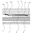
以下に本発明の一実施形態を図を用いて説明する。図1は本発明の一実施形態であり、図1は本発明を適用した裏蓋側に太陽電池を配設した太陽電池付アナログ時計の太陽電池と複合回路の接点部周辺の要部平面図、図2は要部断面図である。なお図6及び図7と同一構造には同一記号を付してその説明を省略する。
【0026】
図1及び図2において、回路支持板6は、金属製の板状部品であり、塑性加工の一方法であるプレス加工、曲げ加工及び絞り加工を利用して成形しており、二次電池の陽極を押圧保持しているため、板全体が+の電気を帯電している。また、太陽電池3と複合回路4をそれぞれ太陽電池接点部(−)7aと回路接点部(−)7bにより電気的に接続する太陽電池接続バネ(−)7を配設しているが、2本の太陽電池接続バネのうち、太陽電池3の下面に配設した電極のうち、陽極3aと回路基板4の陽極側を電気的接続するバネ部を、回路支持板6と一体成形したのが特徴である。
【0027】
即ち、回路支持板6に板バネ形状6aを配設し、この部分に上曲げ加工を加えることによって、その先端部に太陽電池接点部(+)6bを太陽電池3の太陽電池下面電極(+)3aと当接させることによって、陽極側の太陽電池接点部(+)6bを有する板バネ形状6aを回路支持板6と一体で成形した事が特徴である。回路支持板6は、板バネ形状6aとは別の場所に配設したバネ形状の回路接点部6cによって複合回路4に配設した電極パターンと当接しているため、太陽電池3が受光することにより発生する電流は、回路支持板6を介して複合回路4へ流れる。
【0028】
つまり、回路支持板6全体を太陽電池接続バネ(−)7と同等の作用を持つ導電部品として利用することが可能となる。
【0029】
これにより、図6及び図7の従来例においては太陽電池3の陽極側及び陰極側の各電極を接続するため2部品必要であった太陽電池接続バネ10は、図1及び図2においては、太陽電池3の陰極側電極3bと回路基板4の陰極パターンを接続する1本のみとなる。この結果、部品点数を一点削減することが可能となり、完成製品の部品コストを削減すると共に、組立のコストも低減することが可能となる。
【0030】
また、従来部品寸法が小さく、細い板状のバネ部品であったため変形しやすく、取り扱いに注意する必要があった太陽電池接続バネ10を、別の部品と一体成形することにより、部品寸法は大きくなり、取扱性も向上し、作業上のミスによる部品の変形や、部品の脱落による太陽電池3と複合回路4の電気的導通不良を事前に予防することが可能となる。
【0031】
なお、図1及び図2で例を挙げて説明した、裏蓋9側に太陽電池3を配設した太陽電池付アナログ時計モジュールについては、回路支持板6に板バネ形状6aを一体成形しているが、この回路支持板6については、既存の太陽電池付アナログ時計モジュールの回路支持板を流用しているのが特徴である。
【0032】
即ち、この回路支持板6には、時計モジュールと外装部品である裏蓋9を電気的に接続することによって、時計モジュールに静電気が加わったときのアースをとるバネ形状を一体で成形していたが、図1に示す本発明の一実施形態の場合、このアースバネの曲げ加工形状を変更することによって、板バネ形状6aを形成している。これにより、製作費用の高いプレス金型を新規に製作することなく、板バネ形状6aを一体成形した回路支持板6を低コストで形成することが可能となる。
【0033】
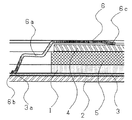
続いて、図3を用いて本発明の第二の実施形態を説明する。図3は本発明の第二の実施形態を示す太陽電池付アナログ時計モジュールの太陽電池接続部回りの要部断面図である。図3に示す太陽電池付アナログ時計は、本発明の第一の実施形態と異なり、地板1と文字板2の間に太陽電池3を配設した従来タイプの物であるが、図3に示すように、回路支持板6から板バネ形状6aを地板1側に延伸し、その先端部6bを太陽電池3の下面に配設した陽極3aと当接させることにより、太陽電池接続バネとして使用しているのが特徴である。
【0034】
図1に示す、太陽電池3が裏蓋9と回路支持板6との間に配設された構造の太陽電池付アナログ時計の場合、太陽電池3と+に帯電した回路支持板6が断面的に近接しているため、回路支持板6に板バネ形状6aを一体で形成する事が可能である。これに対して、図3に示すような、太陽電池3が文字板2と地板1の間に配設された従来の太陽電池付アナログ時計に関しても同様に、回路支持板6に代表される、+に帯電している金属部品に太陽電池接続バネ部を一体成形することにより、部品点数を削減すると共に、部品の取扱性を向上させた構造を実現することが可能となり、本発明の応用範囲は極めて広いと考えられる。
【0035】
続いて第三の実施形態を図4及び図5を用いて説明する。
【0036】
図4は本発明の第三の実施形態の要部平面図、図5は要部断面図であり、8は図示しない巻真による時刻修正機構の一部品である裏押えである。図4及び図5において、裏押え8に板バネ形状8aを一体成形し、この部分に上曲げを加えることによって、太陽電池接点部(+)8bを太陽電池3の下面側の陽極側の電極部3aに当接させているのが特徴である。本例の場合、裏押え8は、板バネ形状8aとは別に一体成形した回路接点部(+)8cによって複合回路4の下面に配設した電極パターンと導通しているため、太陽電池3が受光して発生した電流は、裏押え8を介して複合回路4へと流れる事になる。即ち、裏押え8を陽極側の太陽電池接点部(+)6bを有する板バネ形状6aを形成した回路支持板6と同等の作用を持つ導通部品として利用しているのが特徴である。
【0037】
【発明の効果】
以上のように、本発明は、太陽電池付電子時計において、太陽電池と複合回路を電気的に接続する部品である太陽電池接続バネを対象とし、太陽電池接続バネを別の部品と一体成形することによって部品点数の削減によるコストダウンを実現している。更に、部品の取扱性を向上する事を実現している。
【0038】
具体的には、裏蓋9側に太陽電池を配設した太陽電池付アナログ時計について、太陽電池の陽極と回路を電気的に導通させるバネ部品である太陽電池接続バネを、回路に代表される時計の構成要素を保持する部品である回路支持板と一体成形することによって、部品点数を削減すると共に、板バネ部品であり変形の危険があり、取り扱いに注意を要する部品であった太陽電池接続バネを、より取扱性を向上した形状とする事が可能となる。
【0039】
また、別の実施形態として、太陽電池を地板と文字板の間に配設した従来タイプの太陽電池付アナログ時計において、回路支持板からバネ部を延伸し、太陽電池と接続することによって、本発明の第一の実施形態と同様の効果を得ることが可能となる。
【0040】
また、別の実施形態として、巻真を操作することによって時刻を修正する裏回り機構の一部品である裏押エについて、太陽電池接続バネ部を一体で成形することによって、本発明の第一の実施形態と同様の効果を得ることが可能となる。
【図面の簡単な説明】
【図1】本発明の一実施形態を示す、裏蓋側に太陽電池を配設した太陽電池付アナログ時計の、太陽電池の電極付近の要部平面図である。
【図2】本発明の一実施形態を示す、裏蓋側に太陽電池を配設した太陽電池付アナログ時計の要部断面図である。
【図3】本発明の第二の実施形態を示す、太陽電池付アナログ時計の、太陽電池の電極付近の要部断面図である。
【図4】本発明の第三の実施形態を示す、太陽電池付アナログ時計の要部平面図である。
【図5】本発明の第三の実施形態を示す、太陽電池付アナログ時計の太陽電池の電極付近の要部断面図である。
【図6】従来の太陽電池付アナログ時計の、太陽電池の電極付近の要部断面図である。
【図7】従来の、太陽電池を裏蓋側に配設した太陽電池付アナログ時計の要部断面図である。
【符号の説明】
1 地板
2 文字板
3 太陽電池
3a 太陽電池の下面電極(陽極)
4 複合回路
5 巻真スペーサ
6 回路支持板
6a 板バネ形状
6b 太陽電池接点部(+)
6c 回路接点部(+)
7 太陽電池接続バネ
7a 太陽電池接点部(−)
7b 回路接点部(−)
8 裏押え
8a 板バネ形状
8b 太陽電池接点部(+)
8c 回路接点部(+)
9 裏蓋[0001]
BACKGROUND OF THE INVENTION
The present invention relates to a structure of an electronic timepiece with a solar cell.
[0002]
[Prior art]
Conventionally, timepieces have two display modes: an analog system that displays time using two or three hands and a digital system that displays time using an electro-optical display device typified by liquid crystal or LED, or both. It is well known that it can be broadly classified into a combined combination system. Also, among these analog timepieces, consumers have the presence or absence of a second hand or calendar, as well as the presence or absence of subordinate timekeeping functions such as timer function, chronograph function, alarm function, and age display function. It is also well known that it can be selected according to each preference.
[0003]
In addition, watches have been mainly used as a driving power source in the past by hand-winding or non-rechargeable primary batteries, but recently rechargeable rechargeable batteries using rechargeable secondary batteries. Watches are becoming popular.
[0004]
Examples of rechargeable timepieces that use a secondary battery as a driving power source include timepieces with solar cells that use solar cells that generate power by receiving light, and self-winding timepieces that generate electricity by rotating weights with the movement of their arms. Etc.
[0005]
Among these, the basic structure of an electronic timepiece using a solar cell as a power source will be described below by taking a pointer-type timepiece as an example. FIG. 6 is a cross-sectional view of a main part around a solar cell of a conventional electronic timepiece with a solar cell. In FIG. 6,
[0006]
In FIG. 6, the solar
[0007]
In this example, the
[0008]
However, in this structure, since it is necessary to transmit light through the
[0009]
As an example of one solution to this, unlike the conventional timepiece module with a solar cell in which the
[0010]
An example is shown in FIG. FIG. 7 is a cross-sectional view of the main part in the vicinity of a solar cell connecting portion of a rechargeable pointer type electronic timepiece module in which the
[0011]
In FIG. 7, 9 is a back cover which is an exterior component. The back cover 9 is made of a light-transmitting glass material. By disposing the
[0012]
Here, in FIG. 6 and FIG. 7, the solar
[0013]
In FIG. 6, the solar
[0014]
[Problems to be solved by the invention]
What is important here is how to obtain a structure that realizes the electrical connection between the
[0015]
That is, since the component size of the solar
[0016]
In particular, in the case of a timepiece with a solar battery using a secondary battery, even if a poor electrical connection between the
[0017]
On the other hand, if the power generation and continuity inspection of the
[0018]
In order to solve these problems, the present invention provides a structure in which a solar cell watch module with a
[0019]
[Means for Solving the Problems]
The present invention for solving the above problems includes a base plate that is a base material constituting a timepiece, a solar cell that generates power by receiving light, a secondary battery that stores current generated by the solar cell , A circuit for driving the timepiece by the output of the solar cell , a holding part for holding the components of the timepiece, and a solar cell connection part provided with a solar cell contact portion for electrically connecting the solar cell and the circuit In the electronic timepiece with a solar cell, the holding component is a metal plate-like component that presses and holds the anode of the secondary battery, and the solar cell connection component on the anode side is integrally formed. characterized in that it was.
[0020]
The solar cell connecting component on the anode side is a spring portion provided integrally with the holding component.
[0021]
It said holding part, characterized in that it is a circuit supporting plate for holding the circuit.
[0022]
The timepiece further includes a dial, and the solar cell is disposed between the dial and the main plate .
[0023]
The timepiece further includes a back cover, and the solar cell is disposed between the back cover and the circuit support plate .
[0024]
The solar cell contact portion formed on the solar cell connecting component on the anode side contacts the side opposite to the light receiving surface side of the solar cell.
[0025]
DETAILED DESCRIPTION OF THE INVENTION
Hereinafter, an embodiment of the present invention will be described with reference to the drawings. FIG. 1 is an embodiment of the present invention, and FIG. 1 is a plan view of an essential part around a contact portion of a solar cell and a composite circuit of an analog timepiece with a solar cell in which a solar cell is disposed on a back cover side to which the present invention is applied. FIG. 2 is a cross-sectional view of the main part. Note that the same structure as that in FIGS. 6 and 7 is denoted by the same symbol, and the description thereof is omitted.
[0026]
1 and 2, the
[0027]
That is, a plate spring shape 6 a is arranged on the
[0028]
In other words, the entire
[0029]
Thus, in the conventional example of FIGS. 6 and 7, the solar
[0030]
In addition, since the solar
[0031]
In addition, about the analog timepiece module with a solar cell in which the
[0032]
That is, the
[0033]
Subsequently, a second embodiment of the present invention will be described with reference to FIG. FIG. 3 is a cross-sectional view of the main part around the solar cell connecting portion of the analog timepiece module with solar cell showing the second embodiment of the present invention. Unlike the first embodiment of the present invention, the analog timepiece with solar cell shown in FIG. 3 is of a conventional type in which the
[0034]
In the case of an analog timepiece with a solar cell having a structure in which the
[0035]
Next, a third embodiment will be described with reference to FIGS.
[0036]
FIG. 4 is a plan view of the main part of the third embodiment of the present invention, FIG. 5 is a cross-sectional view of the main part, and 8 is a back presser that is a part of a time correction mechanism using a winding stem (not shown). 4 and 5, the
[0037]
【The invention's effect】
As described above, in the electronic timepiece with a solar cell, the present invention targets a solar cell connection spring that is a component for electrically connecting the solar cell and the composite circuit, and the solar cell connection spring is integrally formed with another component. As a result, the cost is reduced by reducing the number of parts. Furthermore, the handling of parts is improved.
[0038]
Specifically, for an analog timepiece with a solar cell in which a solar cell is disposed on the back cover 9 side, a solar cell connection spring, which is a spring component that electrically connects the solar cell anode and the circuit, is represented by a circuit. By integrally molding with the circuit support plate, which is a component that holds the watch components, the number of components is reduced, and there is a risk of deformation because it is a leaf spring component, which is a component that requires careful handling. It becomes possible to make a spring into the shape which improved the handleability more.
[0039]
Moreover, as another embodiment, in a conventional type analog timepiece with a solar cell in which a solar cell is disposed between a ground plate and a dial plate, the spring portion is extended from the circuit support plate and connected to the solar cell. The same effect as that of the first embodiment can be obtained.
[0040]
As another embodiment, the solar cell connecting spring part is formed integrally with the back presser, which is a part of the back turning mechanism that corrects the time by operating the winding stem. It is possible to obtain the same effect as the embodiment.
[Brief description of the drawings]
FIG. 1 is a plan view of an essential part of a solar cell in the vicinity of an electrode of a solar cell of an analog timepiece with a solar cell in which a solar cell is disposed on a case back side, illustrating an embodiment of the present invention.
FIG. 2 is a cross-sectional view of an essential part of an analog timepiece with a solar cell in which a solar cell is disposed on the back cover side, showing an embodiment of the present invention.
FIG. 3 is a cross-sectional view of a main part near an electrode of a solar cell of an analog timepiece with a solar cell, showing a second embodiment of the present invention.
FIG. 4 is a plan view of an essential part of an analog timepiece with a solar cell, showing a third embodiment of the present invention.
FIG. 5 is a cross-sectional view of a main part near an electrode of a solar battery of an analog timepiece with a solar battery, showing a third embodiment of the present invention.
FIG. 6 is a cross-sectional view of a main part in the vicinity of a solar cell electrode of a conventional analog timepiece with a solar cell.
FIG. 7 is a cross-sectional view of a main part of a conventional analog timepiece with a solar cell in which a solar cell is disposed on the back cover side.
[Explanation of symbols]
DESCRIPTION OF
4
6c Circuit contact (+)
7 Solar cell connection spring 7a Solar cell contact (-)
7b Circuit contact (-)
8 Back
8c Circuit contact (+)
9 Back cover
Claims (6)
前記保持部品は、金属製の板状部品であって、前記二次電池の陽極を押圧保持するものであると共に、陽極側の前記太陽電池接続部品を一体に形成したことを特徴とする太陽電池付電子時計。A ground plane as a base material constituting the timepiece, a solar cell that generates power by receiving light, a secondary battery that stores current generated by the solar cell, and a circuit that drives the timepiece by the output of the solar cell In an electronic timepiece with a solar cell, comprising: a holding component that holds the components of the timepiece; and a solar cell connection component that is provided with a solar cell contact portion that electrically connects the solar cell and the circuit .
The holding component is a metal plate-shaped component that presses and holds the anode of the secondary battery, and the solar cell connecting component on the anode side is integrally formed. Electronic clock with.
Priority Applications (1)
| Application Number | Priority Date | Filing Date | Title |
|---|---|---|---|
| JP2000121968A JP4551531B2 (en) | 2000-04-24 | 2000-04-24 | Electronic clock with solar battery |
Applications Claiming Priority (1)
| Application Number | Priority Date | Filing Date | Title |
|---|---|---|---|
| JP2000121968A JP4551531B2 (en) | 2000-04-24 | 2000-04-24 | Electronic clock with solar battery |
Publications (3)
| Publication Number | Publication Date |
|---|---|
| JP2001305247A JP2001305247A (en) | 2001-10-31 |
| JP2001305247A5 JP2001305247A5 (en) | 2007-03-01 |
| JP4551531B2 true JP4551531B2 (en) | 2010-09-29 |
Family
ID=18632514
Family Applications (1)
| Application Number | Title | Priority Date | Filing Date |
|---|---|---|---|
| JP2000121968A Expired - Lifetime JP4551531B2 (en) | 2000-04-24 | 2000-04-24 | Electronic clock with solar battery |
Country Status (1)
| Country | Link |
|---|---|
| JP (1) | JP4551531B2 (en) |
Families Citing this family (2)
| Publication number | Priority date | Publication date | Assignee | Title |
|---|---|---|---|---|
| JP5157299B2 (en) * | 2007-07-27 | 2013-03-06 | セイコーエプソン株式会社 | Clock and equipment |
| JP2013122423A (en) * | 2011-12-12 | 2013-06-20 | Seiko Epson Corp | Movement and electronic watch |
Citations (5)
| Publication number | Priority date | Publication date | Assignee | Title |
|---|---|---|---|---|
| JPS5313467A (en) * | 1976-06-18 | 1978-02-07 | Seiko Epson Corp | Solar battery-driven timepiece |
| JPS54112074U (en) * | 1978-01-09 | 1979-08-07 | ||
| JPS5564790U (en) * | 1978-10-28 | 1980-05-02 | ||
| JPS62237385A (en) * | 1986-04-08 | 1987-10-17 | Seiko Instr & Electronics Ltd | Solar battery type wrist watch |
| JPH095450A (en) * | 1995-06-15 | 1997-01-10 | Citizen Watch Co Ltd | Wrist watch with solar battery |
-
2000
- 2000-04-24 JP JP2000121968A patent/JP4551531B2/en not_active Expired - Lifetime
Patent Citations (5)
| Publication number | Priority date | Publication date | Assignee | Title |
|---|---|---|---|---|
| JPS5313467A (en) * | 1976-06-18 | 1978-02-07 | Seiko Epson Corp | Solar battery-driven timepiece |
| JPS54112074U (en) * | 1978-01-09 | 1979-08-07 | ||
| JPS5564790U (en) * | 1978-10-28 | 1980-05-02 | ||
| JPS62237385A (en) * | 1986-04-08 | 1987-10-17 | Seiko Instr & Electronics Ltd | Solar battery type wrist watch |
| JPH095450A (en) * | 1995-06-15 | 1997-01-10 | Citizen Watch Co Ltd | Wrist watch with solar battery |
Also Published As
| Publication number | Publication date |
|---|---|
| JP2001305247A (en) | 2001-10-31 |
Similar Documents
| Publication | Publication Date | Title |
|---|---|---|
| US4261049A (en) | Wristwatch with solar cells | |
| US10018968B2 (en) | Solar skeleton watch | |
| JP2019023626A (en) | Skeleton watch including movement independent of case middle | |
| WO2004066042A1 (en) | Electronic timepiece with solar cell | |
| CN105137740B (en) | Watch and clock movement, electronic watch and secondary battery cell | |
| JP4551531B2 (en) | Electronic clock with solar battery | |
| JP2566310Y2 (en) | Module structure of analog clock | |
| JP2014006145A (en) | Solar battery-equipped electronic timepiece | |
| JP4603666B2 (en) | Electronic clock with solar battery | |
| JP6644885B2 (en) | Solar needles for portables such as watches or timekeeping devices | |
| JP2013029469A (en) | Electronic timepiece with solar battery | |
| JP6488590B2 (en) | Conductive member, solar watch, solar cell module, electronic device | |
| JP2001311785A (en) | Electronic wristwatch with solar battery | |
| JP4511681B2 (en) | Analog clock with solar battery | |
| JPH1090440A (en) | Electronic watch mounted with solar battery | |
| JP2001264464A (en) | Electronic apparatus | |
| JP2008039716A (en) | Portable electronic device | |
| JP2013029469A5 (en) | ||
| JPH1048358A (en) | Indicator and electronic apparatus | |
| EP4254080A1 (en) | Module, and timepiece | |
| JP6327381B2 (en) | Secondary battery unit and solar panel electronic watch | |
| JPH10339783A (en) | Electronic time piece | |
| JP6358367B2 (en) | Electronic clock with solar battery | |
| JP2013122423A (en) | Movement and electronic watch | |
| JPS6130790A (en) | Timepiece structure with light receiving power generator |
Legal Events
| Date | Code | Title | Description |
|---|---|---|---|
| A521 | Written amendment |
Free format text: JAPANESE INTERMEDIATE CODE: A523 Effective date: 20070111 |
|
| A621 | Written request for application examination |
Free format text: JAPANESE INTERMEDIATE CODE: A621 Effective date: 20070111 |
|
| A977 | Report on retrieval |
Free format text: JAPANESE INTERMEDIATE CODE: A971007 Effective date: 20100115 |
|
| A131 | Notification of reasons for refusal |
Free format text: JAPANESE INTERMEDIATE CODE: A131 Effective date: 20100126 |
|
| A521 | Written amendment |
Free format text: JAPANESE INTERMEDIATE CODE: A523 Effective date: 20100310 |
|
| RD03 | Notification of appointment of power of attorney |
Free format text: JAPANESE INTERMEDIATE CODE: A7423 Effective date: 20100310 |
|
| TRDD | Decision of grant or rejection written | ||
| A01 | Written decision to grant a patent or to grant a registration (utility model) |
Free format text: JAPANESE INTERMEDIATE CODE: A01 Effective date: 20100629 |
|
| A01 | Written decision to grant a patent or to grant a registration (utility model) |
Free format text: JAPANESE INTERMEDIATE CODE: A01 |
|
| A61 | First payment of annual fees (during grant procedure) |
Free format text: JAPANESE INTERMEDIATE CODE: A61 Effective date: 20100712 |
|
| R150 | Certificate of patent or registration of utility model |
Ref document number: 4551531 Country of ref document: JP Free format text: JAPANESE INTERMEDIATE CODE: R150 Free format text: JAPANESE INTERMEDIATE CODE: R150 |
|
| FPAY | Renewal fee payment (event date is renewal date of database) |
Free format text: PAYMENT UNTIL: 20130716 Year of fee payment: 3 |
|
| S533 | Written request for registration of change of name |
Free format text: JAPANESE INTERMEDIATE CODE: R313533 |
|
| R350 | Written notification of registration of transfer |
Free format text: JAPANESE INTERMEDIATE CODE: R350 |
|
| R250 | Receipt of annual fees |
Free format text: JAPANESE INTERMEDIATE CODE: R250 |
|
| EXPY | Cancellation because of completion of term |