JP4551457B2 - Rotary cutting machine with fixing device - Google Patents
Rotary cutting machine with fixing device Download PDFInfo
- Publication number
- JP4551457B2 JP4551457B2 JP2008019510A JP2008019510A JP4551457B2 JP 4551457 B2 JP4551457 B2 JP 4551457B2 JP 2008019510 A JP2008019510 A JP 2008019510A JP 2008019510 A JP2008019510 A JP 2008019510A JP 4551457 B2 JP4551457 B2 JP 4551457B2
- Authority
- JP
- Japan
- Prior art keywords
- pair
- rotary cutting
- sandwiching
- cutting device
- workpiece
- Prior art date
- Legal status (The legal status is an assumption and is not a legal conclusion. Google has not performed a legal analysis and makes no representation as to the accuracy of the status listed.)
- Expired - Fee Related
Links
Images


Description
本発明は、主にC型鋼などの被工作物に穿孔などの所要の作業を行う回転切削装置に係り、特に、被工作物に固定するための固定装置を備えた回転切削装置に関する。 The present invention relates to a rotary cutting apparatus that mainly performs a required work such as drilling on a workpiece such as C-shaped steel, and more particularly to a rotary cutting apparatus that includes a fixing device for fixing to a workpiece.
この種の回転切削装置は、一般的に、回転切削装置本体の下面に固定装置が装着されるようになっており、この固定装置は、C型鋼などの被工作物に挟着固定する一対の挟着部材が相互に対向して平行に設けられ、この一対の挟着部材を相互に近づいたり離したりできるようガイド部材により支持し、この挟着部材に左右ネジの設けられた両ネジをネジ係合し、該両ネジを回転させることにより、該挟着部材をガイド部材に沿って相互に近づくように動かして、それらの間に被工作物を挟着固定するようになっている。(例えば、特許文献1参照)
この種の回転切削装置は、工事現場に運んで、作業者が被切削物に締着固定して作業を行うのが普通であり、従って、当該回転切削装置はより軽量であることが求められるが、上記のような形式の固定装置では、挟着部材を案内するためのガイド部材を必要とするために重量が大きくなり、取り扱いにくくなるという問題がある。 This type of rotary cutting device is usually carried to a construction site, and an operator usually performs the work by fastening and fixing to a workpiece. Therefore, the rotary cutting device is required to be lighter. However, in the fixing device of the above type, there is a problem that a guide member for guiding the sandwiching member is required, which increases the weight and makes it difficult to handle.
本発明は、この点に鑑み、固定装置をより軽量にすることにより取り扱いやすくした回転切削装置を提供することを目的とする。 In view of this point, an object of the present invention is to provide a rotary cutting device that is easy to handle by making the fixing device lighter.
すなわち、本発明は、
回転切削装置本体(以下に述べる実施形態においては参照番号22で示す。以下同じ)と、
該回転切削装置本体に装着され、該回転切削装置本体を被工作物に取り外し可能に固定する固定装置(24)と、
を有し、該固定装置(24)が、
該回転切削装置本体(22)に装着されるフレーム(26)と、
該フレームに、一定間隔をあけ相互に平行な一対の枢軸線(A)を中心に枢動可能に取り付けられた一対の挟着部材(36)であって、それぞれ、該枢軸線(A)から離れた先端側に相互に対向するように設けられ、被工作物(W)を挟着可能とされた挟着部(38)を有する一対の挟着部材(36)と、
該一対の挟着部材(36)間に設けられ、該一対の枢軸線(A)を結ぶ線に平行な方向に伸縮可能とされ、該一対の挟着部材(36)に枢着された伸縮部材(46)と、
該一対の挟着部材(36)を相互に連接し、一方の挟着部材がその枢軸線(A)の周りで時計方向及び反時計方向のいずれかに枢動するときに、他方の挟着部材がその枢軸線(A)の周りでその反対方向に枢動するようにする連接部材(66)と
を有する固定装置付き回転切削装置を提供する。
That is, the present invention
A rotary cutting device main body (in the embodiment described below, indicated by
A fixing device (24) attached to the rotary cutting device main body and removably fixing the rotary cutting device main body to a workpiece;
And the fixing device (24)
A frame (26) attached to the rotary cutting device body (22);
A pair of sandwiching members (36) attached to the frame so as to be pivotable about a pair of pivots (A) parallel to each other at regular intervals, respectively, from the pivots (A) A pair of clamping members (36) having a clamping part (38) provided so as to oppose each other at the distal end side and capable of clamping the workpiece (W);
Expansion / contraction provided between the pair of sandwiching members (36) and capable of extending and contracting in a direction parallel to a line connecting the pair of pivot axes (A) and pivotally mounted on the pair of sandwiching members (36). A member (46);
When the pair of clamping members (36) are connected to each other and one of the clamping members pivots around the pivot (A) in either the clockwise direction or the counterclockwise direction, the other clamping member A rotating cutting device with a fixing device having an articulating member (66) which causes the member to pivot about its pivot axis (A) in the opposite direction.
この回転切削装置の固定装置では、挟着部材(36)を従来の装置のように平行移動するものではなく、枢動することにより被工作物を挟着固定するようになっており、挟着部材を案内するためのガイドやそれに関連する部品を必要としないので、軽量にすることができる。従って、作業員は、当該回転切削装置を容易に所要の位置に設定したりすることができる。 In this rotary cutting device fixing device, the clamping member (36) is not moved in parallel as in the conventional device, but the workpiece is clamped and fixed by pivoting. Since a guide for guiding members and parts related thereto are not required, the weight can be reduced. Therefore, the worker can easily set the rotary cutting device at a required position.
具体的には、
上記フレーム(26)が、
回転切削装置本体(22)に装着される基部(28)と、
該基部から上記一対の挟着部材(36)の間で延びる被工作物当接部(32)と
を有し、
被工作物当接部(32)を被工作物(W)に当接させた状態で、挟着部(38)による被工作物(W)の挟着を行うようにすることができる。
In particular,
The frame (26)
A base (28) attached to the rotary cutting device body (22);
A workpiece contact portion (32) extending between the pair of clamping members (36) from the base portion,
The workpiece (W) can be clamped by the clamping portion (38) in a state where the workpiece contact portion (32) is in contact with the workpiece (W).
更に具体的には、
上記フレーム(26)の基部(28)が板状とされ、該被工作物当接部(32)が該板状の基部(28)の両側縁から延びる脚部(30)と、該脚部の先端から折り曲げられた先端部(32)とを有し、該折り曲げられた先端部の基部(28)から離れる方向に面する面を被工作物(W)に当接するようにすることができる。
More specifically,
The base (28) of the frame (26) has a plate shape, the workpiece contact portion (32) has leg portions (30) extending from both side edges of the plate-like base portion (28), and the leg portions. A tip portion (32) bent from the tip of the workpiece, and a surface facing away from the base portion (28) of the bent tip portion can be brought into contact with the workpiece (W). .
上記一対の挟着部材(36)の挟着部(38)が、相互に向かう方向に突出するスパイクを有し、被工作物を挟着するときに、該スパイクが被工作物(W)に押圧されるようにすることが好ましい。 The sandwiching portions (38) of the pair of sandwiching members (36) have spikes projecting in directions toward each other, and when the workpiece is sandwiched, the spikes are placed on the workpiece (W). It is preferable to be pressed.
この場合、上記一対の挟着部材(36)の挟着部(38)が被工作物(W)を挟むときに、該スパイクが上記枢軸線(A)から該枢軸線(A)相互を結ぶ線に対して垂直に延びる線よりも内側となるようにすることが好ましい。 In this case, when the sandwiching portions (38) of the pair of sandwiching members (36) sandwich the workpiece (W), the spikes connect the pivots (A) to the pivots (A). It is preferable to be inside the line extending perpendicularly to the line.
このようにすることにより、スパイクが被工作物(W)をフレーム(26)に向けて押し上げる力をかけることになり、被工作物をより強く保持することが可能となる。 By doing so, the spike applies a force for pushing the workpiece (W) toward the frame (26), and the workpiece can be held more strongly.
上記伸縮部材は、一方の挟着部材(36)に枢着されたメネジ部材(48)と、該メネジ部材(48)にネジ係合されて他方の挟着部材(36)に枢着されたオネジ部材(50)とからなるものとすることができる。 The telescopic member is a female screw member (48) pivotally attached to one clamping member (36), and is screwed to the female screw member (48) and pivotally attached to the other clamping member (36). It can consist of a male screw member (50).
上記一対の挟着部材(36)は、それぞれ、その枢軸線(A)よりも外側で該枢軸線に平行に延びる板状の中央板部(36−1)と、該中央板部の上記枢軸線(A)が延びる方向での両側縁から他方の挟着部材(36)に向けて延びた一対の両側板部(36−2)とからなる全体としてコ字状の部材とされ、該挟着部(38)が中央板部(36−1)に固定された板状部材から構成され、上記伸縮部材(46)が挟着部材(36)の両側板部(36−2)間に配置され該両側板部に枢着されるようにすることができる。 Each of the pair of sandwiching members (36) includes a plate-like central plate portion (36-1) extending outside the pivot axis (A) and parallel to the pivot axis, and the pivot shaft of the central plate portion. A generally U-shaped member comprising a pair of both side plate portions (36-2) extending from both side edges in the direction in which the line (A) extends toward the other clamping member (36), The attaching part (38) is composed of a plate-like member fixed to the central plate part (36-1), and the expansion / contraction member (46) is disposed between both side plate parts (36-2) of the sandwiching member (36). And can be pivotally attached to the both side plate portions.
また、上記一対の挟着部材(36)の両側板部(36−2)が、該一対の挟着部材(36)が同時に互いに反対方向に回動できる状態で相互に近接した縁を有し、該近接した両側板部間に連接部材(66)が設けられるようにすることができる。 Further, both side plates (36-2) of the pair of sandwiching members (36) have edges close to each other in a state where the pair of sandwiching members (36) can simultaneously rotate in opposite directions. A connecting member (66) may be provided between the adjacent side plate portions.
具体的には、該一対の挟着部材(36)の該両側板部(36−2)の相互に近接した縁が互いに向き合う凹部(62,64)を有し、連接部材(66)は該凹部(62,64)間に嵌合されるようにすることができる。 Specifically, the both side plates (36-2) of the pair of sandwiching members (36) have recesses (62, 64) in which the edges close to each other face each other, and the connecting member (66) It can be fitted between the recesses (62, 64).
別の形態としては、上記連接部材が、上記一対の挟着部材(36)の両側板部(36−2)の相互に近接した縁が相互にかみ合う歯車歯からなるようにすることもできる。 As another form, the connecting member may be formed of gear teeth in which edges adjacent to each other of both side plate portions (36-2) of the pair of sandwiching members (36) mesh with each other.
以下、本発明に係る回転切削装置の実施形態を図面に基づき説明する。 Hereinafter, an embodiment of a rotary cutting device according to the present invention will be described with reference to the drawings.
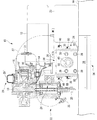
図1は、本発明に係る回転切削装置10を示している。
FIG. 1 shows a
図示のように、この回転切削装置10は、電動モータ12と、該電動モータの出力軸14に駆動連結された複数の歯車16´からなる歯車列16と、該歯車列によって回転駆動されるシャフト18と、該シャフトの下端に取り付けられた筒状の切削工具20と、該シャフトを上下動させるためのラックピニオン装置21とを有する回転切削装置本体22を備える。該回転切削装置本体は、当業者には知られているものであり詳細は省略する。尚、この回転切削装置本体は、筒状の切削工具20の先端にその外部から切削油を給油するためのノズル25、給油タンク23、給油タンクからノズルへ切削油を通す給油管27、該給油管に介装された手動ポンプ29及び逆止弁31からなる給油装置を備えており、作業者が手動ポンプ29のゴムなどの弾性部材でできた帽子状ポンプ部材29´を押すことにより給油を行うことができるようになっている。
As shown in the figure, the
回転切削装置本体22の下部には、該回転切削装置本体をC型鋼などの穿孔を行う被工作物に固定するための固定装置24が設けられている。
A
該固定装置24は、該回転切削装置本体22に装着固定されるフレーム26を有する。該フレーム26は、図1で見て左右に延びる板状の基部28と、該基部の左右両端から下方に延びる一対の脚部30と、該脚の先端を左右方向外側に水平に曲げた被工作物当接部32とを有している。脚部30は、図3及び図4に示すように、基部28に続く幅広の部分30−1と該幅広の部分30−1に続く幅狭の部分30−2とからなる。基部28は回転切削装置本体22に固定され、被工作物当接部32は、穿孔作業を行うときに、被工作物Wに当接される。尚、基部28及び幅の狭い部分30−2には、それぞれ図5及び図2に示すように、開口28−1、開口30−2´が設けられている。
The
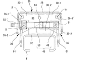
固定装置24は更に、図2乃至図4で見て左右方向で間隔をあけられ、これら図面の紙面に対して垂直に延びる一対の枢軸線Aを中心にフレーム26に枢動可能に取り付けられた一対の挟着部材36を有する。この挟着部材は、それぞれ、枢軸線Aから離れた先端側に相互に対向するように設けられて被工作物Wを挟着可能とされた挟着部36を有する。具体的には、各挟着部材36は、図5の底面図に示すように、中央板部36−1と該中央板部の(図5で見て)上下端から延びる両側板部36−2とからなるコ字状の部材とされている。中央板部36−1には、ボルト39により取り付けられて図1で見て左右方向に延びた板状部材により挟着部38が構成されている。各挟着部材の両側板部36−2の幅広の部分30−1の間には、枢軸線Aに沿って延び、フレーム30の幅広部分30−1の内壁面に接するようにして筒状のメネジ部材(図示せず)が設けられ、該幅広部分30−1の外壁面に接するように位置する両側板部36−2の外側からボルト40(図2)が該両側板部36−2及び幅広部分30−1を通して該メネジ部材の両端部分にネジ螺合され、それにより、挟着部材36が枢軸線Aを中心にフレーム30に枢着されている。
The
固定装置24は更に、一対の挟着部材36間に設けられ、枢軸線A間を結ぶ線に平行な方向に伸縮可能とされ、該一対の挟着部材36に枢着された伸縮部材46を有する。具体的には、該伸縮部材46は、図3及び図4に示すように、一方の挟着部材38に枢軸線Bを中心に枢着されたメネジ部材48と、他方の挟着部材36に枢軸線Bを中心に枢着されて、メネジ部材48にネジ係合されたオネジ部材50とを有する。より具体的には、オネジ部材50には、その長手軸線に直交するようにして枢軸線Bに沿って延び挟着部材36の両側板部36−2の内壁面にまで到る棒状部材52が設けられ、挟着部材36の両側板部36−2の外側から通されたボルト54が該棒状部材の両端に螺合し、これにより、オネジ部材50は、枢軸線Bを中心に、挟着部材36(の両側板部)に対して枢動可能とされている。メネジ部材48には同様に該メネジ部材の長手枢軸線に直交し枢軸線Bに沿ってメネジ部材48を貫通して(図1)延びて挟着部材の両側板部36−2の内壁面にまで到る一対の棒状部材58が設けられ、挟着部材36の両側板部36−2の外側から通されたボルト60が該棒状部材の両端に螺合し、これにより、メネジ部材48は、枢軸線Bを中心に、挟着部材36(の両側板部)に対して枢動可能とされている。オネジ部材50の図3で見て左端には、当該オネジ部材をその枢軸線を中心に回転させ、メネジ部材48との螺合を調節して当該伸縮部材46を伸縮させるための操作杆50´が設けられている。図3で見て左側の挟着部材36には、この操作杆50´を外に通すための開口36−1´が設けられており、右側の挟着部材36にも同様の開口36−1´が設けられている。作業者は、この操作杆を把持して回転することにより、被工作物Wに対する挟着部材36による挟着固定・固定解除の操作を行う。
The fixing
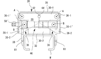
両挟着部材36の両側板部36−2は相互に隣接するように設けられており、その隣接する縁には対向する半円状の凹部62,64が設けられ、両凹部間には円形の連接部材66が嵌合されている。この連接部材66は、一方の挟着部材36がその枢軸線Aの周りで時計方向及び反時計方向のいずれかに枢動するときに、他方の挟着部材36がその枢軸線Aの周りでその反対方向に枢動するようにして、両挟着部材が同じ方向に枢動するのを阻止する。
Both side plate portions 36-2 of both sandwiching
図2乃至図4に示すように、挟着部材36の挟着部38には、相互に向かう方向に小さく突出するスパイク61が設けられており、被工作物Wを挟着するときに、該スパイク61が被工作物に押圧されるようになっている。図示の実施形態においては、図4から分かるように、挟着部材36の挟着部38が被工作物Wを挟むときに、該スパイク61が枢軸線Aから該枢軸線A相互を結ぶ線に対して垂直に延びる線よりも内側となるようにされており、挟着を行ったときに、挟着部38が該被工作物を上方に持ち上げるような力を作用するようにしている。
As shown in FIGS. 2 to 4, the sandwiching
以上、本発明の実施形態を説明したが、本発明はこれに限定するものではなく、例えば、両側板部36−2の互いに隣接する縁を、それぞれの枢軸線を中心とした円弧状とし、相互に噛合する歯車歯を設けるようにすることもできる。 As mentioned above, although embodiment of this invention was described, this invention is not limited to this, For example, let the edge which mutually adjoins the both-sides board part 36-2 be circular arc shape centering on each pivot axis, It is also possible to provide gear teeth that mesh with each other.
回転切削装置10;電動モータ12;出力軸14;歯車16´;歯車列16;シャフト18;筒状の切削工具20;回転切削装置本体22;給油タンク23;固定装置24;ノズル25;フレーム26;給油管27;基部28;ポンプ装置29;ポンプ部材29´;脚部30;幅広の部分30−1;幅狭の部分30−2;被工作物当接部32;挟着部材36;中央板部36−1;両側板部36−2;挟着部38;ボルト40;伸縮部材46;メネジ部材48;オネジ部材50;棒状部材52;ボルト54;ボルト60;スパイク61;凹部62,64;連接部材66;枢軸線A;枢軸線B;被工作物W
Claims (10)
該回転切削装置本体に装着され、該回転切削装置本体を被工作物に取り外し可能に固定する固定装置と、
を有し、該固定装置が、
該回転切削装置本体に装着されるフレームと、
該フレームに、一定間隔をあけ相互に平行な一対の枢軸線を中心に枢動可能に取り付けられた一対の挟着部材であって、それぞれ、該枢軸線から離れた先端側に相互に対向するように設けられ、被工作物を挟着可能とされた挟着部を有する一対の挟着部材と、
該一対の挟着部材間に設けられ、該一対の枢軸線を結ぶ線に平行な方向に伸縮可能とされ、該一対の挟着部材に枢着された伸縮部材と、
該一対の挟着部材相互を連接し、一方の挟着部材がその枢軸線の周りで時計方向及び反時計方向のいずれかに枢動するときに、他方の挟着部材がその枢軸線の周りでその反対方向に枢動するようにする連接部材と
を有する固定装置付き回転切削装置。 A rotary cutting device body;
A fixing device mounted on the rotary cutting device main body and removably fixing the rotary cutting device main body to a workpiece;
The fixing device has
A frame attached to the rotary cutting device body;
A pair of clamping members attached to the frame so as to be pivotable about a pair of pivots parallel to each other at a predetermined interval, and facing each other at the distal end side away from the pivots A pair of clamping members provided with a clamping part that is capable of clamping a workpiece;
An expansion / contraction member provided between the pair of sandwiching members, capable of expanding and contracting in a direction parallel to a line connecting the pair of pivot axes, and pivotally mounted on the pair of sandwiching members;
The pair of sandwiching members are connected to each other, and when one sandwiching member pivots around the pivot axis in either the clockwise direction or the counterclockwise direction, the other sandwiching member moves around the pivot axis. And a connecting member that pivots in the opposite direction.
回転切削装置本体に装着される基部と、
該基部から該一対の挟着部材の間で延びる被工作物当接部と
を有し、
該被工作物当接部を該被工作物に当接させた状態で、該挟着部による被工作物の挟着を行うようにした請求項1に記載の固定装置付き回転切削装置。 The frame
A base mounted on the rotary cutting device body;
A workpiece contact portion extending between the pair of clamping members from the base, and
The rotary cutting device with a fixing device according to claim 1, wherein the workpiece is clamped by the clamping portion in a state where the workpiece contact portion is in contact with the workpiece.
Priority Applications (3)
| Application Number | Priority Date | Filing Date | Title |
|---|---|---|---|
| JP2008019510A JP4551457B2 (en) | 2008-01-30 | 2008-01-30 | Rotary cutting machine with fixing device |
| TW98102996A TW200940220A (en) | 2008-01-30 | 2009-01-23 | Rotary cutting device with fixing device |
| CN200910138706A CN101537579A (en) | 2008-01-30 | 2009-01-24 | Rotary cutting apparatus with fixed device |
Applications Claiming Priority (1)
| Application Number | Priority Date | Filing Date | Title |
|---|---|---|---|
| JP2008019510A JP4551457B2 (en) | 2008-01-30 | 2008-01-30 | Rotary cutting machine with fixing device |
Publications (2)
| Publication Number | Publication Date |
|---|---|
| JP2009178796A JP2009178796A (en) | 2009-08-13 |
| JP4551457B2 true JP4551457B2 (en) | 2010-09-29 |
Family
ID=41033167
Family Applications (1)
| Application Number | Title | Priority Date | Filing Date |
|---|---|---|---|
| JP2008019510A Expired - Fee Related JP4551457B2 (en) | 2008-01-30 | 2008-01-30 | Rotary cutting machine with fixing device |
Country Status (3)
| Country | Link |
|---|---|
| JP (1) | JP4551457B2 (en) |
| CN (1) | CN101537579A (en) |
| TW (1) | TW200940220A (en) |
Families Citing this family (2)
| Publication number | Priority date | Publication date | Assignee | Title |
|---|---|---|---|---|
| CN102126155B (en) * | 2010-01-16 | 2013-04-10 | 苏州宝时得电动工具有限公司 | Workbench |
| JP6124642B2 (en) * | 2013-03-26 | 2017-05-10 | 三菱電機株式会社 | Power management system and refrigerator |
Citations (6)
| Publication number | Priority date | Publication date | Assignee | Title |
|---|---|---|---|---|
| JPS545882U (en) * | 1977-06-15 | 1979-01-16 | ||
| JPS5781011U (en) * | 1980-11-04 | 1982-05-19 | ||
| JPS61131210U (en) * | 1985-02-05 | 1986-08-16 | ||
| JPH04135135A (en) * | 1990-09-21 | 1992-05-08 | Suzuki Motor Corp | Work jig |
| JPH06173572A (en) * | 1992-09-30 | 1994-06-21 | Kobori Tekko Kk | Device for boring hole in intersection of shape steels disposed at right angle |
| JPH06193378A (en) * | 1992-12-28 | 1994-07-12 | Kobori Tekko Kk | Method and device for boring intersection of shape steel crossing at right angle |
-
2008
- 2008-01-30 JP JP2008019510A patent/JP4551457B2/en not_active Expired - Fee Related
-
2009
- 2009-01-23 TW TW98102996A patent/TW200940220A/en not_active IP Right Cessation
- 2009-01-24 CN CN200910138706A patent/CN101537579A/en active Pending
Patent Citations (6)
| Publication number | Priority date | Publication date | Assignee | Title |
|---|---|---|---|---|
| JPS545882U (en) * | 1977-06-15 | 1979-01-16 | ||
| JPS5781011U (en) * | 1980-11-04 | 1982-05-19 | ||
| JPS61131210U (en) * | 1985-02-05 | 1986-08-16 | ||
| JPH04135135A (en) * | 1990-09-21 | 1992-05-08 | Suzuki Motor Corp | Work jig |
| JPH06173572A (en) * | 1992-09-30 | 1994-06-21 | Kobori Tekko Kk | Device for boring hole in intersection of shape steels disposed at right angle |
| JPH06193378A (en) * | 1992-12-28 | 1994-07-12 | Kobori Tekko Kk | Method and device for boring intersection of shape steel crossing at right angle |
Also Published As
| Publication number | Publication date |
|---|---|
| TW200940220A (en) | 2009-10-01 |
| TWI355306B (en) | 2012-01-01 |
| CN101537579A (en) | 2009-09-23 |
| JP2009178796A (en) | 2009-08-13 |
Similar Documents
| Publication | Publication Date | Title |
|---|---|---|
| EP3544920B1 (en) | Method for installation and alignment apparatus for alignment of a guide rail of a lift system | |
| JP6815737B2 (en) | Chain disassembly machine | |
| US20090162158A1 (en) | Hand Held Portable Drill Leverage Unit | |
| JP2006205258A (en) | Bending device for bending machine | |
| JP4551457B2 (en) | Rotary cutting machine with fixing device | |
| US9827706B2 (en) | Mobile waterstop welding apparatus | |
| KR100971033B1 (en) | Quick adjustable pipe wrench | |
| JP2009178798A (en) | Rotary cutting device with oil-feeding device | |
| JP2007203381A (en) | Handle for operating wheel | |
| KR20170111220A (en) | Clamp for scaffold pipe | |
| JP5886345B2 (en) | Hydraulic cutter | |
| DE102013101083A1 (en) | Auxiliary tool for mounting shock absorber for reducing oscillation in e.g. motor car, has rotary element comprising screw hole with internal thread that is precisely fitted to inner pipe body and rotatably arranged at end section | |
| KR101775959B1 (en) | Clamp for scaffold boards | |
| US20170312930A1 (en) | Cutting tool | |
| KR20130017279A (en) | Clamping device | |
| WO2006022553A1 (en) | Pipe cutter | |
| JP2011247073A (en) | Automatic coupler tightening device and mechanical connection method of members utilizing the same | |
| US5785467A (en) | Lever bar machining apparatus | |
| EP2275282A1 (en) | Wallpaper loosening device | |
| KR101707075B1 (en) | drill jig | |
| ATE371786T1 (en) | SMOOTHING DEVICE FOR CONCRETE PANELS AND OTHER AGGREGATES | |
| TWM440852U (en) | Improved clamp plier tool structure | |
| KR101669949B1 (en) | A pressure device for screw bolt | |
| KR200460064Y1 (en) | Portable Vise for clamping a welding piece | |
| KR200469734Y1 (en) | Centering Device for Flange hole of Pipe |
Legal Events
| Date | Code | Title | Description |
|---|---|---|---|
| A621 | Written request for application examination |
Free format text: JAPANESE INTERMEDIATE CODE: A621 Effective date: 20100126 |
|
| A131 | Notification of reasons for refusal |
Free format text: JAPANESE INTERMEDIATE CODE: A131 Effective date: 20100413 |
|
| A521 | Written amendment |
Free format text: JAPANESE INTERMEDIATE CODE: A523 Effective date: 20100614 |
|
| TRDD | Decision of grant or rejection written | ||
| A01 | Written decision to grant a patent or to grant a registration (utility model) |
Free format text: JAPANESE INTERMEDIATE CODE: A01 Effective date: 20100706 |
|
| A01 | Written decision to grant a patent or to grant a registration (utility model) |
Free format text: JAPANESE INTERMEDIATE CODE: A01 |
|
| A61 | First payment of annual fees (during grant procedure) |
Free format text: JAPANESE INTERMEDIATE CODE: A61 Effective date: 20100709 |
|
| R150 | Certificate of patent or registration of utility model |
Free format text: JAPANESE INTERMEDIATE CODE: R150 |
|
| FPAY | Renewal fee payment (event date is renewal date of database) |
Free format text: PAYMENT UNTIL: 20130716 Year of fee payment: 3 |
|
| LAPS | Cancellation because of no payment of annual fees |