JP4550109B2 - Hollow body manufacturing method and apparatus for reducing air consumption - Google Patents
Hollow body manufacturing method and apparatus for reducing air consumption Download PDFInfo
- Publication number
- JP4550109B2 JP4550109B2 JP2007504285A JP2007504285A JP4550109B2 JP 4550109 B2 JP4550109 B2 JP 4550109B2 JP 2007504285 A JP2007504285 A JP 2007504285A JP 2007504285 A JP2007504285 A JP 2007504285A JP 4550109 B2 JP4550109 B2 JP 4550109B2
- Authority
- JP
- Japan
- Prior art keywords
- medium
- pressure
- hollow body
- reservoir
- storage tank
- Prior art date
- Legal status (The legal status is an assumption and is not a legal conclusion. Google has not performed a legal analysis and makes no representation as to the accuracy of the status listed.)
- Active
Links
Images


Classifications
-
- B—PERFORMING OPERATIONS; TRANSPORTING
- B29—WORKING OF PLASTICS; WORKING OF SUBSTANCES IN A PLASTIC STATE IN GENERAL
- B29C—SHAPING OR JOINING OF PLASTICS; SHAPING OF MATERIAL IN A PLASTIC STATE, NOT OTHERWISE PROVIDED FOR; AFTER-TREATMENT OF THE SHAPED PRODUCTS, e.g. REPAIRING
- B29C49/00—Blow-moulding, i.e. blowing a preform or parison to a desired shape within a mould; Apparatus therefor
- B29C49/42—Component parts, details or accessories; Auxiliary operations
- B29C49/78—Measuring, controlling or regulating
- B29C49/783—Measuring, controlling or regulating blowing pressure
-
- B—PERFORMING OPERATIONS; TRANSPORTING
- B29—WORKING OF PLASTICS; WORKING OF SUBSTANCES IN A PLASTIC STATE IN GENERAL
- B29C—SHAPING OR JOINING OF PLASTICS; SHAPING OF MATERIAL IN A PLASTIC STATE, NOT OTHERWISE PROVIDED FOR; AFTER-TREATMENT OF THE SHAPED PRODUCTS, e.g. REPAIRING
- B29C49/00—Blow-moulding, i.e. blowing a preform or parison to a desired shape within a mould; Apparatus therefor
- B29C49/18—Blow-moulding, i.e. blowing a preform or parison to a desired shape within a mould; Apparatus therefor using several blowing steps
-
- B—PERFORMING OPERATIONS; TRANSPORTING
- B29—WORKING OF PLASTICS; WORKING OF SUBSTANCES IN A PLASTIC STATE IN GENERAL
- B29C—SHAPING OR JOINING OF PLASTICS; SHAPING OF MATERIAL IN A PLASTIC STATE, NOT OTHERWISE PROVIDED FOR; AFTER-TREATMENT OF THE SHAPED PRODUCTS, e.g. REPAIRING
- B29C49/00—Blow-moulding, i.e. blowing a preform or parison to a desired shape within a mould; Apparatus therefor
- B29C49/42—Component parts, details or accessories; Auxiliary operations
- B29C49/64—Heating or cooling preforms, parisons or blown articles
- B29C49/66—Cooling by refrigerant introduced into the blown article
-
- B—PERFORMING OPERATIONS; TRANSPORTING
- B29—WORKING OF PLASTICS; WORKING OF SUBSTANCES IN A PLASTIC STATE IN GENERAL
- B29C—SHAPING OR JOINING OF PLASTICS; SHAPING OF MATERIAL IN A PLASTIC STATE, NOT OTHERWISE PROVIDED FOR; AFTER-TREATMENT OF THE SHAPED PRODUCTS, e.g. REPAIRING
- B29C49/00—Blow-moulding, i.e. blowing a preform or parison to a desired shape within a mould; Apparatus therefor
- B29C49/42—Component parts, details or accessories; Auxiliary operations
- B29C49/46—Component parts, details or accessories; Auxiliary operations characterised by using particular environment or blow fluids other than air
- B29C2049/4602—Blowing fluids
- B29C2049/4605—Blowing fluids containing an inert gas, e.g. helium
- B29C2049/4608—Nitrogen
-
- B—PERFORMING OPERATIONS; TRANSPORTING
- B29—WORKING OF PLASTICS; WORKING OF SUBSTANCES IN A PLASTIC STATE IN GENERAL
- B29C—SHAPING OR JOINING OF PLASTICS; SHAPING OF MATERIAL IN A PLASTIC STATE, NOT OTHERWISE PROVIDED FOR; AFTER-TREATMENT OF THE SHAPED PRODUCTS, e.g. REPAIRING
- B29C49/00—Blow-moulding, i.e. blowing a preform or parison to a desired shape within a mould; Apparatus therefor
- B29C49/42—Component parts, details or accessories; Auxiliary operations
- B29C49/46—Component parts, details or accessories; Auxiliary operations characterised by using particular environment or blow fluids other than air
- B29C2049/4602—Blowing fluids
- B29C2049/4611—Blowing fluids containing a reactive gas
- B29C2049/462—Oxygen
-
- B—PERFORMING OPERATIONS; TRANSPORTING
- B29—WORKING OF PLASTICS; WORKING OF SUBSTANCES IN A PLASTIC STATE IN GENERAL
- B29C—SHAPING OR JOINING OF PLASTICS; SHAPING OF MATERIAL IN A PLASTIC STATE, NOT OTHERWISE PROVIDED FOR; AFTER-TREATMENT OF THE SHAPED PRODUCTS, e.g. REPAIRING
- B29C49/00—Blow-moulding, i.e. blowing a preform or parison to a desired shape within a mould; Apparatus therefor
- B29C49/42—Component parts, details or accessories; Auxiliary operations
- B29C49/46—Component parts, details or accessories; Auxiliary operations characterised by using particular environment or blow fluids other than air
- B29C2049/4602—Blowing fluids
- B29C2049/465—Blowing fluids being incompressible
- B29C2049/4655—Blowing fluids being incompressible water
-
- B—PERFORMING OPERATIONS; TRANSPORTING
- B29—WORKING OF PLASTICS; WORKING OF SUBSTANCES IN A PLASTIC STATE IN GENERAL
- B29C—SHAPING OR JOINING OF PLASTICS; SHAPING OF MATERIAL IN A PLASTIC STATE, NOT OTHERWISE PROVIDED FOR; AFTER-TREATMENT OF THE SHAPED PRODUCTS, e.g. REPAIRING
- B29C49/00—Blow-moulding, i.e. blowing a preform or parison to a desired shape within a mould; Apparatus therefor
- B29C49/42—Component parts, details or accessories; Auxiliary operations
- B29C49/58—Blowing means
- B29C2049/5841—Plural independent blowing paths
-
- B—PERFORMING OPERATIONS; TRANSPORTING
- B29—WORKING OF PLASTICS; WORKING OF SUBSTANCES IN A PLASTIC STATE IN GENERAL
- B29C—SHAPING OR JOINING OF PLASTICS; SHAPING OF MATERIAL IN A PLASTIC STATE, NOT OTHERWISE PROVIDED FOR; AFTER-TREATMENT OF THE SHAPED PRODUCTS, e.g. REPAIRING
- B29C49/00—Blow-moulding, i.e. blowing a preform or parison to a desired shape within a mould; Apparatus therefor
- B29C49/42—Component parts, details or accessories; Auxiliary operations
- B29C49/62—Venting means
- B29C2049/6271—Venting means for venting blowing medium, e.g. using damper or silencer
-
- B—PERFORMING OPERATIONS; TRANSPORTING
- B29—WORKING OF PLASTICS; WORKING OF SUBSTANCES IN A PLASTIC STATE IN GENERAL
- B29C—SHAPING OR JOINING OF PLASTICS; SHAPING OF MATERIAL IN A PLASTIC STATE, NOT OTHERWISE PROVIDED FOR; AFTER-TREATMENT OF THE SHAPED PRODUCTS, e.g. REPAIRING
- B29C49/00—Blow-moulding, i.e. blowing a preform or parison to a desired shape within a mould; Apparatus therefor
- B29C49/42—Component parts, details or accessories; Auxiliary operations
- B29C49/64—Heating or cooling preforms, parisons or blown articles
- B29C49/6604—Thermal conditioning of the blown article
- B29C2049/6606—Cooling the article
- B29C2049/6607—Flushing blown articles
- B29C2049/6615—Flushing blown articles and exhausting through the blowing means
-
- B—PERFORMING OPERATIONS; TRANSPORTING
- B29—WORKING OF PLASTICS; WORKING OF SUBSTANCES IN A PLASTIC STATE IN GENERAL
- B29C—SHAPING OR JOINING OF PLASTICS; SHAPING OF MATERIAL IN A PLASTIC STATE, NOT OTHERWISE PROVIDED FOR; AFTER-TREATMENT OF THE SHAPED PRODUCTS, e.g. REPAIRING
- B29C49/00—Blow-moulding, i.e. blowing a preform or parison to a desired shape within a mould; Apparatus therefor
- B29C49/42—Component parts, details or accessories; Auxiliary operations
- B29C49/64—Heating or cooling preforms, parisons or blown articles
- B29C49/6604—Thermal conditioning of the blown article
- B29C2049/6606—Cooling the article
- B29C2049/6607—Flushing blown articles
- B29C2049/6646—Flushing blown articles while keeping the final blowing pressure in the article
-
- B—PERFORMING OPERATIONS; TRANSPORTING
- B29—WORKING OF PLASTICS; WORKING OF SUBSTANCES IN A PLASTIC STATE IN GENERAL
- B29C—SHAPING OR JOINING OF PLASTICS; SHAPING OF MATERIAL IN A PLASTIC STATE, NOT OTHERWISE PROVIDED FOR; AFTER-TREATMENT OF THE SHAPED PRODUCTS, e.g. REPAIRING
- B29C49/00—Blow-moulding, i.e. blowing a preform or parison to a desired shape within a mould; Apparatus therefor
- B29C49/42—Component parts, details or accessories; Auxiliary operations
- B29C49/64—Heating or cooling preforms, parisons or blown articles
- B29C49/6604—Thermal conditioning of the blown article
- B29C2049/6606—Cooling the article
- B29C2049/6676—Cooling the article the medium being oriented towards special areas of the blown article
- B29C2049/6692—Bottom area
-
- B—PERFORMING OPERATIONS; TRANSPORTING
- B29—WORKING OF PLASTICS; WORKING OF SUBSTANCES IN A PLASTIC STATE IN GENERAL
- B29C—SHAPING OR JOINING OF PLASTICS; SHAPING OF MATERIAL IN A PLASTIC STATE, NOT OTHERWISE PROVIDED FOR; AFTER-TREATMENT OF THE SHAPED PRODUCTS, e.g. REPAIRING
- B29C49/00—Blow-moulding, i.e. blowing a preform or parison to a desired shape within a mould; Apparatus therefor
- B29C49/42—Component parts, details or accessories; Auxiliary operations
- B29C49/78—Measuring, controlling or regulating
- B29C49/783—Measuring, controlling or regulating blowing pressure
- B29C2049/7831—Measuring, controlling or regulating blowing pressure characterised by pressure values or ranges
-
- B—PERFORMING OPERATIONS; TRANSPORTING
- B29—WORKING OF PLASTICS; WORKING OF SUBSTANCES IN A PLASTIC STATE IN GENERAL
- B29C—SHAPING OR JOINING OF PLASTICS; SHAPING OF MATERIAL IN A PLASTIC STATE, NOT OTHERWISE PROVIDED FOR; AFTER-TREATMENT OF THE SHAPED PRODUCTS, e.g. REPAIRING
- B29C49/00—Blow-moulding, i.e. blowing a preform or parison to a desired shape within a mould; Apparatus therefor
- B29C49/42—Component parts, details or accessories; Auxiliary operations
- B29C49/78—Measuring, controlling or regulating
- B29C49/783—Measuring, controlling or regulating blowing pressure
- B29C2049/7832—Blowing with two or more pressure levels
- B29C2049/7833—Blowing with three or more pressure levels
-
- B—PERFORMING OPERATIONS; TRANSPORTING
- B29—WORKING OF PLASTICS; WORKING OF SUBSTANCES IN A PLASTIC STATE IN GENERAL
- B29C—SHAPING OR JOINING OF PLASTICS; SHAPING OF MATERIAL IN A PLASTIC STATE, NOT OTHERWISE PROVIDED FOR; AFTER-TREATMENT OF THE SHAPED PRODUCTS, e.g. REPAIRING
- B29C2949/00—Indexing scheme relating to blow-moulding
- B29C2949/07—Preforms or parisons characterised by their configuration
- B29C2949/0715—Preforms or parisons characterised by their configuration the preform having one end closed
-
- B—PERFORMING OPERATIONS; TRANSPORTING
- B29—WORKING OF PLASTICS; WORKING OF SUBSTANCES IN A PLASTIC STATE IN GENERAL
- B29C—SHAPING OR JOINING OF PLASTICS; SHAPING OF MATERIAL IN A PLASTIC STATE, NOT OTHERWISE PROVIDED FOR; AFTER-TREATMENT OF THE SHAPED PRODUCTS, e.g. REPAIRING
- B29C49/00—Blow-moulding, i.e. blowing a preform or parison to a desired shape within a mould; Apparatus therefor
- B29C49/02—Combined blow-moulding and manufacture of the preform or the parison
- B29C49/04—Extrusion blow-moulding
-
- B—PERFORMING OPERATIONS; TRANSPORTING
- B29—WORKING OF PLASTICS; WORKING OF SUBSTANCES IN A PLASTIC STATE IN GENERAL
- B29C—SHAPING OR JOINING OF PLASTICS; SHAPING OF MATERIAL IN A PLASTIC STATE, NOT OTHERWISE PROVIDED FOR; AFTER-TREATMENT OF THE SHAPED PRODUCTS, e.g. REPAIRING
- B29C49/00—Blow-moulding, i.e. blowing a preform or parison to a desired shape within a mould; Apparatus therefor
- B29C49/02—Combined blow-moulding and manufacture of the preform or the parison
- B29C49/06—Injection blow-moulding
-
- B—PERFORMING OPERATIONS; TRANSPORTING
- B29—WORKING OF PLASTICS; WORKING OF SUBSTANCES IN A PLASTIC STATE IN GENERAL
- B29C—SHAPING OR JOINING OF PLASTICS; SHAPING OF MATERIAL IN A PLASTIC STATE, NOT OTHERWISE PROVIDED FOR; AFTER-TREATMENT OF THE SHAPED PRODUCTS, e.g. REPAIRING
- B29C49/00—Blow-moulding, i.e. blowing a preform or parison to a desired shape within a mould; Apparatus therefor
- B29C49/08—Biaxial stretching during blow-moulding
- B29C49/10—Biaxial stretching during blow-moulding using mechanical means for prestretching
- B29C49/12—Stretching rods
-
- B—PERFORMING OPERATIONS; TRANSPORTING
- B29—WORKING OF PLASTICS; WORKING OF SUBSTANCES IN A PLASTIC STATE IN GENERAL
- B29C—SHAPING OR JOINING OF PLASTICS; SHAPING OF MATERIAL IN A PLASTIC STATE, NOT OTHERWISE PROVIDED FOR; AFTER-TREATMENT OF THE SHAPED PRODUCTS, e.g. REPAIRING
- B29C49/00—Blow-moulding, i.e. blowing a preform or parison to a desired shape within a mould; Apparatus therefor
- B29C49/28—Blow-moulding apparatus
- B29C49/30—Blow-moulding apparatus having movable moulds or mould parts
- B29C49/36—Blow-moulding apparatus having movable moulds or mould parts rotatable about one axis
-
- B—PERFORMING OPERATIONS; TRANSPORTING
- B29—WORKING OF PLASTICS; WORKING OF SUBSTANCES IN A PLASTIC STATE IN GENERAL
- B29C—SHAPING OR JOINING OF PLASTICS; SHAPING OF MATERIAL IN A PLASTIC STATE, NOT OTHERWISE PROVIDED FOR; AFTER-TREATMENT OF THE SHAPED PRODUCTS, e.g. REPAIRING
- B29C49/00—Blow-moulding, i.e. blowing a preform or parison to a desired shape within a mould; Apparatus therefor
- B29C49/42—Component parts, details or accessories; Auxiliary operations
- B29C49/4284—Means for recycling or reusing auxiliaries or materials, e.g. blowing fluids or energy
- B29C49/42845—Recycling or reusing of fluid, e.g. pressure
- B29C49/42855—Blowing fluids, e.g. reducing fluid consumption
-
- B—PERFORMING OPERATIONS; TRANSPORTING
- B29—WORKING OF PLASTICS; WORKING OF SUBSTANCES IN A PLASTIC STATE IN GENERAL
- B29C—SHAPING OR JOINING OF PLASTICS; SHAPING OF MATERIAL IN A PLASTIC STATE, NOT OTHERWISE PROVIDED FOR; AFTER-TREATMENT OF THE SHAPED PRODUCTS, e.g. REPAIRING
- B29C49/00—Blow-moulding, i.e. blowing a preform or parison to a desired shape within a mould; Apparatus therefor
- B29C49/42—Component parts, details or accessories; Auxiliary operations
- B29C49/4284—Means for recycling or reusing auxiliaries or materials, e.g. blowing fluids or energy
- B29C49/4286—Recycling or reusing of heat energy
-
- B—PERFORMING OPERATIONS; TRANSPORTING
- B29—WORKING OF PLASTICS; WORKING OF SUBSTANCES IN A PLASTIC STATE IN GENERAL
- B29C—SHAPING OR JOINING OF PLASTICS; SHAPING OF MATERIAL IN A PLASTIC STATE, NOT OTHERWISE PROVIDED FOR; AFTER-TREATMENT OF THE SHAPED PRODUCTS, e.g. REPAIRING
- B29C49/00—Blow-moulding, i.e. blowing a preform or parison to a desired shape within a mould; Apparatus therefor
- B29C49/42—Component parts, details or accessories; Auxiliary operations
- B29C49/4289—Valve constructions or configurations, e.g. arranged to reduce blowing fluid consumption
-
- B—PERFORMING OPERATIONS; TRANSPORTING
- B29—WORKING OF PLASTICS; WORKING OF SUBSTANCES IN A PLASTIC STATE IN GENERAL
- B29C—SHAPING OR JOINING OF PLASTICS; SHAPING OF MATERIAL IN A PLASTIC STATE, NOT OTHERWISE PROVIDED FOR; AFTER-TREATMENT OF THE SHAPED PRODUCTS, e.g. REPAIRING
- B29C49/00—Blow-moulding, i.e. blowing a preform or parison to a desired shape within a mould; Apparatus therefor
- B29C49/42—Component parts, details or accessories; Auxiliary operations
- B29C49/62—Venting means
-
- B—PERFORMING OPERATIONS; TRANSPORTING
- B29—WORKING OF PLASTICS; WORKING OF SUBSTANCES IN A PLASTIC STATE IN GENERAL
- B29K—INDEXING SCHEME ASSOCIATED WITH SUBCLASSES B29B, B29C OR B29D, RELATING TO MOULDING MATERIALS OR TO MATERIALS FOR MOULDS, REINFORCEMENTS, FILLERS OR PREFORMED PARTS, e.g. INSERTS
- B29K2027/00—Use of polyvinylhalogenides or derivatives thereof as moulding material
- B29K2027/06—PVC, i.e. polyvinylchloride
-
- B—PERFORMING OPERATIONS; TRANSPORTING
- B29—WORKING OF PLASTICS; WORKING OF SUBSTANCES IN A PLASTIC STATE IN GENERAL
- B29K—INDEXING SCHEME ASSOCIATED WITH SUBCLASSES B29B, B29C OR B29D, RELATING TO MOULDING MATERIALS OR TO MATERIALS FOR MOULDS, REINFORCEMENTS, FILLERS OR PREFORMED PARTS, e.g. INSERTS
- B29K2067/00—Use of polyesters or derivatives thereof, as moulding material
-
- B—PERFORMING OPERATIONS; TRANSPORTING
- B29—WORKING OF PLASTICS; WORKING OF SUBSTANCES IN A PLASTIC STATE IN GENERAL
- B29K—INDEXING SCHEME ASSOCIATED WITH SUBCLASSES B29B, B29C OR B29D, RELATING TO MOULDING MATERIALS OR TO MATERIALS FOR MOULDS, REINFORCEMENTS, FILLERS OR PREFORMED PARTS, e.g. INSERTS
- B29K2627/00—Use of polyvinylhalogenides or derivatives thereof for preformed parts, e.g. for inserts
- B29K2627/06—PVC, i.e. polyvinylchloride
-
- B—PERFORMING OPERATIONS; TRANSPORTING
- B29—WORKING OF PLASTICS; WORKING OF SUBSTANCES IN A PLASTIC STATE IN GENERAL
- B29K—INDEXING SCHEME ASSOCIATED WITH SUBCLASSES B29B, B29C OR B29D, RELATING TO MOULDING MATERIALS OR TO MATERIALS FOR MOULDS, REINFORCEMENTS, FILLERS OR PREFORMED PARTS, e.g. INSERTS
- B29K2995/00—Properties of moulding materials, reinforcements, fillers, preformed parts or moulds
- B29K2995/0037—Other properties
- B29K2995/004—Semi-crystalline
-
- B—PERFORMING OPERATIONS; TRANSPORTING
- B29—WORKING OF PLASTICS; WORKING OF SUBSTANCES IN A PLASTIC STATE IN GENERAL
- B29K—INDEXING SCHEME ASSOCIATED WITH SUBCLASSES B29B, B29C OR B29D, RELATING TO MOULDING MATERIALS OR TO MATERIALS FOR MOULDS, REINFORCEMENTS, FILLERS OR PREFORMED PARTS, e.g. INSERTS
- B29K2995/00—Properties of moulding materials, reinforcements, fillers, preformed parts or moulds
- B29K2995/0037—Other properties
- B29K2995/0041—Crystalline
-
- Y—GENERAL TAGGING OF NEW TECHNOLOGICAL DEVELOPMENTS; GENERAL TAGGING OF CROSS-SECTIONAL TECHNOLOGIES SPANNING OVER SEVERAL SECTIONS OF THE IPC; TECHNICAL SUBJECTS COVERED BY FORMER USPC CROSS-REFERENCE ART COLLECTIONS [XRACs] AND DIGESTS
- Y02—TECHNOLOGIES OR APPLICATIONS FOR MITIGATION OR ADAPTATION AGAINST CLIMATE CHANGE
- Y02P—CLIMATE CHANGE MITIGATION TECHNOLOGIES IN THE PRODUCTION OR PROCESSING OF GOODS
- Y02P70/00—Climate change mitigation technologies in the production process for final industrial or consumer products
- Y02P70/10—Greenhouse gas [GHG] capture, material saving, heat recovery or other energy efficient measures, e.g. motor control, characterised by manufacturing processes, e.g. for rolling metal or metal working
Abstract
Description
本発明は、輪郭を有するブロー成形金型内において熱可塑性プラスチックからなる加熱されたパリソンから成形される中空本体特に耐熱性中空本体の製造方法に関するものである。本発明は、さらに、このような方法がそれにより実行可能な装置に関するものである。 The present invention relates to a method for producing a hollow body, particularly a heat-resistant hollow body, which is molded from a heated parison made of a thermoplastic in a blow mold having a contour. The invention further relates to an apparatus by which such a method can be performed.
食品工業において、特に飲料工業においても、かなり前から、食品ないしは飲料を熱可塑性プラスチックからなる中空本体特にPETボトル内に充填する方向に移行してきている。飲料の保存性を延長させるために、例えば高温充填のような種々の方法が行われている。高温で充填されるべき飲料を例えばPETボトルのようなプラスチック容器内に充填したい場合、この容器に高い耐熱性が必要とされる。 In the food industry, in particular in the beverage industry, it has been moving for a long time in the direction of filling foods or beverages into hollow bodies made of thermoplastics, especially PET bottles. In order to extend the shelf life of beverages, various methods such as high temperature filling have been performed. When it is desired to fill a beverage to be filled at a high temperature in a plastic container such as a PET bottle, the container needs to have high heat resistance.
既知の耐熱性中空本体の製造方法および装置においては、パリソンがある圧力の媒体により予備ブロー成形され(予備ブロー成形工程)、および第2のステップにおいて、より高い圧力の媒体により仕上ブロー成形される(仕上ブロー成形工程)。仕上ブロー成形圧力は、プラスチック・ブランクがブロー成形金型の内壁に圧着されるような高さである。この圧力は、金型の輪郭を、成形されるボトルに理想的に転送するために、ある時間保持される。製造されるべき中空本体が耐熱性中空本体(いわゆる高温充填ボトル)である場合、金型壁が加熱され、輪郭を型出しするために、成形されるボトルがこの金型壁に圧着される。この加熱された内壁にボトルを保持することは、プラスチックを一部結晶化させる理由からであり、これにより、高い熱安定性および形状安定性を達成することができる。しかしながら、プラスチックの結晶化が強すぎた場合、プラスチックの好ましくない変色いわゆる乳白色化が発生する。金型から取り出すときのボトルの十分な形状安定性を確保し且つ上記の変色を阻止するために、高温充填が可能なプラスチック・ボトルの製造工程においては、プラスチック・ボトルを冷却することがきわめて重要である。冷却は例えばボトルの内部において行うことが可能である。このために、種々の媒体が使用可能である。圧縮空気による冷却が広く行われている。冷却空気ないしは洗浄空気はしばしば中空延伸棒を介してボトルに供給される。空気循環による十分な冷却を保証するためには、ボトル内壁から熱を搬出する空気流れを発生させるために、例えば弁が開放される。このとき、たいていの場合、いわゆる洗浄空気は空気供給源からボトルおよび消音器を介して大気中に流出する。この冷却工程後に、ボトル内に存在し且つなお残留圧力を有する残留媒体が排出される。たいていの場合、これは消音器を介して行われる。この方法の欠点は、特に冷却過程ないしは洗浄過程に基づく空気消費量がきわめて高いことである。 In the known heat-resistant hollow body manufacturing method and apparatus, the parison is pre-blow molded with a medium of a certain pressure (pre-blow molding process), and in the second step is finish blow molded with a medium of higher pressure. (Finish blow molding process). The finish blow molding pressure is such that the plastic blank is pressed against the inner wall of the blow mold. This pressure is held for a period of time to ideally transfer the mold profile to the bottle to be molded. If the hollow body to be manufactured is a heat-resistant hollow body (so-called hot filling bottle), the mold wall is heated and the bottle to be molded is pressed against this mold wall in order to mold the contour. Holding the bottle on the heated inner wall is for the reason that the plastic is partially crystallized, whereby high thermal stability and shape stability can be achieved. However, if the crystallization of the plastic is too strong, an undesirable discoloration of the plastic, so-called milky whitening, occurs. In order to ensure sufficient shape stability of the bottle when it is removed from the mold and to prevent the above discoloration, it is extremely important to cool the plastic bottle in the manufacturing process of plastic bottles that can be filled at high temperature. It is. Cooling can be performed, for example, inside the bottle. Various media can be used for this purpose. Cooling with compressed air is widely performed. Cooling or cleaning air is often supplied to the bottle via a hollow draw bar. In order to ensure sufficient cooling by air circulation, for example, a valve is opened to generate an air flow that carries heat away from the bottle inner wall. At this time, in most cases, so-called cleaning air flows out from the air supply source into the atmosphere via the bottle and the silencer. After this cooling step, the residual medium present in the bottle and still having a residual pressure is discharged. In most cases this is done via a silencer. The disadvantage of this method is that the air consumption is particularly high due to the cooling or cleaning process.
その空気消費量が既知の工程の空気消費量よりも著しく低減される、中空本体特に耐熱性中空本体の製造工程を提供することが本発明の課題である。さらに、本発明による工程に従って作業する装置を提供することが本発明の課題である。 It is an object of the present invention to provide a process for producing a hollow body, in particular a heat-resistant hollow body, whose air consumption is significantly reduced from that of known processes. Furthermore, it is an object of the present invention to provide an apparatus for working according to the process according to the present invention.
方法に関するこの課題を解決するために、請求項1に記載の方法ステップが実行される。この方法ステップにより、はじめに、第1の媒体貯槽内に圧力p1で貯蔵されている媒体、この場合好ましくは圧縮空気が、ブロー成形金型内に存在するパリソン内に導入され且つパリソンを変形させる(予備ブロー成形工程)。圧縮空気のほかに他の媒体が使用されてもよいことは当然である。この場合、蒸気状媒体または液状媒体のような他の物質状態のみならず、他の組成もまた考えられる。空気のほかに、例えば窒素または酸素またはこれらからなる種々の混合物のような種々のガスが使用されてもよい。蒸気状媒体として例えば水蒸気が使用されてもよい。しかしながら、例えば水のような種々の液状媒体により成形工程を実行することもまた考えられる。本方法は特定のプラスチック・プリフォームの使用に限定されず、したがって、例えばPETパリソン、PVCパリソン等にも使用可能である。 To solve this problem with the method, the method steps according to claim 1 are carried out. This method step initially introduces a medium stored at a pressure p1 in the first medium reservoir, in this case preferably compressed air, into the parison present in the blow mold and deforms the parison ( Pre-blow molding process). Of course, other media besides compressed air may be used. In this case, other compositions are also conceivable, as well as other material states such as vaporous or liquid media. In addition to air, various gases such as nitrogen or oxygen or various mixtures of these may be used. For example, water vapor may be used as the vaporous medium. However, it is also conceivable to carry out the molding process with various liquid media, for example water. The method is not limited to the use of specific plastic preforms and can therefore be used, for example, for PET parisons, PVC parisons and the like.
少なくとも1つの媒体貯槽は種々のタイプで形成可能である。例えば球形貯槽、角形貯槽またはリング状貯槽が考えられる。上記以外の他の貯槽形状もまた可能であり且つそれらが除外されないことは明らかである。 The at least one media reservoir can be formed of various types. For example, a spherical storage tank, a rectangular storage tank or a ring-shaped storage tank can be considered. Obviously other reservoir shapes other than those described above are also possible and are not excluded.
予備吹込媒体の圧力p1は2−20バール(2×10⁵−20×105パスカル)であり、この場合、好ましい実施形態においては、圧力が3−10バール(3×10⁵−10×105パスカル)である。ブロー成形工程のこの工程においては、パリソンを縦方向に延ばすために、延伸棒がパリソンの開口からパリソンの底部の方向に移動することにより、パリソンの延伸もまた開始される。延伸棒は、ブロー成形工程の種々の要求に対応するために、中実に形成されるのみならず、切込みが設けられていても、または完全に中空に形成されていてもよい。 The pressure p1 of the pre-blowing medium is 2-20 bar (2 × 10 5 -20 × 10 5 Pascals), in which case in a preferred embodiment the pressure is 3-10 bar (3 × 10 5 -10 × 10). 5 Pascals). In this step of the blow molding process, stretching of the parison is also initiated by moving the stretching bar from the opening of the parison toward the bottom of the parison to extend the parison in the longitudinal direction. In order to meet the various requirements of the blow molding process, the draw bar is not only formed solid, but may also be provided with cuts or formed completely hollow.
中空本体が予備ブロー成形されたのちに、再度圧力p2の媒体が導入され、この場合、p2はp1より高い。これにより、中空本体はそのブロー成形が完了し且つブロー成形金型内壁に圧着される(仕上ブロー成形工程)。一方で、仕上吹込媒体は異なる物質状態を有する異なる媒体であってもよい。仕上ブロー成形においては予備ブロー成形と同じ媒体が使用されることが好ましく、好ましい実施形態においては、これは圧縮空気である。仕上吹込媒体の圧力p2は15−45バール(15×105−45×105パスカル)であり、20−30バール(20×105−30×105パスカル)の圧力が好ましい。特に好ましい変更態様においては、23−26バール(23×105−26×105パスカル)の仕上吹込媒体が使用される。 After the hollow body is pre-blow molded, the medium with pressure p2 is again introduced, where p2 is higher than p1. Thereby, the blow molding of the hollow main body is completed, and the hollow main body is pressure-bonded to the inner wall of the blow molding die (finish blow molding process). On the other hand, the finish blowing medium may be different media having different material states. In finish blow molding, the same medium as in pre-blow molding is preferably used, and in a preferred embodiment this is compressed air. The pressure p2 of the finish blowing medium is 15-45 bar (15 × 10 5 -45 × 10 5 Pascals), preferably 20-30 bar (20 × 10 5 -30 × 10 5 Pascals). In a particularly preferred variant, a finish blowing medium of 23-26 bar (23 × 10 5 -26 × 10 5 Pascals) is used.
耐熱性中空本体の製造においては、製造されるべき容器の部分結晶化したがって安定化を達成するために、ブロー成形金型内壁が加熱される。仕上ブロー成形のステップにより加熱されたブロー成形金型内壁に圧着された中空本体を冷却し且つこれにより型外しにおける好ましくない逆収縮硬化を回避するために、他のステップにおいて、圧力p3の洗浄/冷却媒体が貯槽から中空本体内に導入される。冷却媒体の導入は、製造されるべき容器の上端に装着された吹込ノズルを介して行われても、または中空延伸棒を介して行われてもよい。中空延伸棒は下側に開放されていてもよく、このとき、中空延伸棒は、容器の底部がきわめて適切に冷却可能であるという利点を有している。ブロー成形工程に基づき、例えば首部領域ないしは胴部領域内よりも底部領域内により多くの材料が存在するので、このことは特に重要である。しかしながら、より多くの材料とは、中空本体の型外しにおいて形状安定性を保証するために、搬出されなければならないより多くの蓄積熱もまた意味している。冷却空気が中空延伸棒を介して中空本体内に導入される場合、好ましい実施形態においては、容器内壁の特定の領域をきわめて適切に冷却可能にするために、下側に向けられた開口に追加して、側部にもいくつかの穴が存在する。冷却媒体は異なる組成および異なる状態であってもよい。好ましい実施形態においては、冷却媒体は予備ブロー成形および仕上ブロー成形と同じ媒体である。この場合、圧力p3は30−45バール(30×105−45×105パスカル)、好ましくは37−45バール(37×105−45×105パスカル)である。冷却/洗浄媒体貯槽は他の貯槽と同じタイプに形成されていることが好ましい。 In the production of a heat resistant hollow body, the inner wall of the blow mold is heated in order to achieve partial crystallization and thus stabilization of the container to be produced. In order to cool the hollow body crimped to the inner wall of the blow mold heated by the finish blow molding step and thereby avoid undesired reverse shrinkage hardening in the mold release, in another step the cleaning / A cooling medium is introduced from the reservoir into the hollow body. The introduction of the cooling medium may be effected via a blow nozzle attached to the upper end of the container to be produced, or via a hollow stretch rod. The hollow stretch bar may be open to the bottom, where the hollow stretch rod has the advantage that the bottom of the container can be cooled very appropriately. This is particularly important because there is more material in the bottom region than in the neck or barrel region, for example, based on the blow molding process. However, more material also means more accumulated heat that must be removed to ensure shape stability in the mold release of the hollow body. When cooling air is introduced into the hollow body via a hollow stretch rod, in a preferred embodiment, it is added to the opening directed downwards in order to allow a particular area of the container inner wall to be cooled very well. And there are some holes on the side. The cooling medium may have different compositions and different states. In a preferred embodiment, the cooling medium is the same medium as pre-blow molding and finish blow molding. In this case, the pressure p3 is 30-45 bar (30 × 10 5 -45 × 10 5 Pascals), preferably 37-45 bar (37 × 10 5 -45 × 10 5 Pascals). The cooling / cleaning medium reservoir is preferably formed of the same type as the other reservoirs.
洗浄空気圧力p3は仕上ブロー成形空気の圧力p2より大きいので、洗浄空気は、この工程においては、ボトルを冷却するのみならず、製造されるべき中空本体の輪郭を完全に型付けする(型付け工程)という課題もまた有している。製造されるべき中空本体の輪郭の完全な型付けが仕上ブロー成形工程内のみにおいてはもはや完了されないことにより、仕上ブロー成形工程の工程時間は、ほぼ輪郭の型付けのために実行されるであろう部分だけ短縮可能である。工程のこの部分においては、媒体貯槽即ち冷却媒体貯槽と中空本体との接続配管が開放されるだけでよい。この時点においてボトル内にかかっているp2と、p3との差圧に基づき、洗浄/冷却空気媒体貯槽と中空本体との接続配管の開放後に冷却媒体は中空本体内に流入するが、中空本体内の圧力が洗浄/冷却媒体貯槽内の圧力に等しくなるまでの間だけ流入すればよい。冷却媒体の中空本体内へのこの制限された流入に基づき、中空本体の冷却は工程のこの時点においてはまだ終了されていない。中空本体内の圧力が冷却/洗浄媒体貯槽内の圧力に等しくなったとき、ボトルの輪郭の所定の型付けおよび容器壁における結晶化を支援するために、この状態がある時間保持される。 Since the cleaning air pressure p3 is greater than the pressure p2 of the finish blow molding air, the cleaning air not only cools the bottle in this process but also completely molds the contour of the hollow body to be manufactured (molding process). It also has the problem. Since the complete molding of the contour of the hollow body to be produced is no longer completed only within the finish blow molding process, the process time of the finish blow molding process is the part that will be performed for the contour molding almost. Can only be shortened. In this part of the process, the connection pipe between the medium storage tank or cooling medium storage tank and the hollow body need only be opened. The cooling medium flows into the hollow body after the connection pipe between the cleaning / cooling air medium storage tank and the hollow body is opened based on the differential pressure between p2 and p3 applied to the bottle at this point. It is only necessary to flow in until the pressure is equal to the pressure in the cleaning / cooling medium storage tank. Based on this limited flow of cooling medium into the hollow body, the cooling of the hollow body has not yet been terminated at this point in the process. When the pressure in the hollow body is equal to the pressure in the cooling / cleaning medium reservoir, this state is held for a period of time to assist in pre-determining the bottle profile and crystallization at the vessel wall.
この型付け工程ののちに、ボトルと、洗浄空気の圧力より低い圧力を有する媒体貯槽との接続が形成されることによりボトルの冷却が継続して行われ、一方、ボトルと洗浄/冷却空気媒体貯槽との接続は開放されたままである。これにより、洗浄空気は、ボトルを介して、より低い圧力を有する媒体貯槽内に流入し、且つボトルは空気運動により内部から冷却される。この場合、冷却空気は熱を受け取り且つ熱をより低い圧力を有する媒体貯槽に搬送する。即ち、既知の工程とは異なり、本発明による工程においては、ボトルの洗浄は周囲の方向に行われず、他の媒体貯槽の方向に行われる。この他の貯槽内には既に過圧がかかっているので、周囲の方向への洗浄に比較して洗浄空気流量は減少する。これは洗浄時間の延長により補償される。仕上ブロー成形における工程時間が短縮されるので、洗浄時間の延長にもかかわらず、ブロー成形工程の全体が延長される必要はない。 After this molding step, the bottle is continuously cooled by forming a connection between the bottle and a medium reservoir having a pressure lower than the pressure of the wash air, while the bottle and the wash / cooling air medium reservoir are The connection to remains open. Thereby, the cleaning air flows into the medium storage tank having a lower pressure through the bottle, and the bottle is cooled from the inside by air movement. In this case, the cooling air receives heat and conveys the heat to a media reservoir having a lower pressure. That is, unlike the known processes, in the process according to the invention, the bottles are not washed in the direction of the surroundings but in the direction of the other medium reservoir. Since the overpressure is already applied in the other storage tanks, the cleaning air flow rate is reduced as compared with the cleaning in the surrounding direction. This is compensated by extending the cleaning time. Since the process time in finish blow molding is shortened, the entire blow molding process does not need to be extended despite the increase in cleaning time.
即ち、その方向に洗浄される媒体貯槽にはボトルを介して洗浄/冷却空気媒体貯槽から空気が供給されるので、固有のプロセス空気供給源はもはや必要ではない。本発明による工程における洗浄空気は最も高い圧力を有する媒体であるので、ブロー成形工程の他のいずれの媒体貯槽の方向にも洗浄可能である。しかしながら、それぞれの媒体貯槽内にかかっている圧力は異なるので、異なる圧力差およびこの結果としての異なる圧力均衡時間に基づき、洗浄/冷却時間は適合且つ調節されなければならない。 That is, since the media reservoir being cleaned in that direction is supplied with air from the cleaning / cooling air media reservoir via the bottle, a unique process air supply is no longer necessary. Since the cleaning air in the process according to the invention is the medium with the highest pressure, it can be cleaned in the direction of any other medium reservoir in the blow molding process. However, since the pressure applied in each media reservoir is different, the cleaning / cooling time must be adapted and adjusted based on the different pressure differences and the resulting different pressure balance times.
冷却工程の終了時に上記の洗浄空気流れが再び停止され且つなおボトル内に存在する残留圧縮空気が排出され、これにより、ボトル内にはほぼ周囲条件が支配している。この残留空気の排出は周囲の方向に対してのみならず他の媒体貯槽の方向にも実行可能である。 At the end of the cooling process, the washing air flow is stopped again and the residual compressed air still present in the bottle is discharged, so that the ambient conditions dominate in the bottle. This discharge of residual air can be carried out not only in the direction of the surroundings but also in the direction of other medium reservoirs.
従属請求項により、本発明による方法を変更形態として形成する可能性が存在する。
少なくとも1つの媒体は圧縮空気であることが好ましい。好ましい実施形態においては、媒体のタイプはいかなるプロセス・ステップにおいても変更されない。これにより、このときに好ましくない混合が行われることなく、異なる貯槽間において媒体を往復搬送することが可能である。圧力がほぼ一定のレベルに保持されるだけでよい。
Depending on the dependent claims, there is the possibility of forming the method according to the invention as a variant.
Preferably the at least one medium is compressed air. In the preferred embodiment, the media type is not changed in any process step. Accordingly, it is possible to reciprocate the medium between different storage tanks without undesired mixing at this time. The pressure need only be maintained at a substantially constant level.
この有利な変更形態においては、媒体貯槽内の圧力をできるだけ一定に保持するために、媒体貯槽に例えば均圧タンクのような均圧装置が設けられる。異なる圧力レベルを有する媒体貯槽間の接続が形成されるので、これは特に目的に適うものであり、この場合、貯槽内の目標圧力はできるだけ変化しないようにすべきである。種々の均圧装置が考えられるが、全て、媒体貯槽内の圧力変化が目標値の10%を超えないように設計されているべきである。 In this advantageous variant, in order to keep the pressure in the medium reservoir as constant as possible, the medium reservoir is provided with a pressure equalizing device, for example a pressure equalizing tank. This is particularly suitable because a connection is made between media reservoirs with different pressure levels, in which case the target pressure in the reservoir should be as small as possible. Various pressure equalization devices are possible, but all should be designed so that the pressure change in the media reservoir does not exceed 10% of the target value.
しかしながら、均圧装置の代わりに、ブロー成形ステーションの手前に圧力を制御する絞り弁を挿入することもまた考えられ、この圧力は、この場合、最終的にそれぞれのプロセス・ステップに対して必要とされるよりも常にやや高く供給されなければならない。 However, instead of a pressure equalizing device, it is also conceivable to insert a throttle valve that controls the pressure in front of the blow molding station, which in this case is ultimately required for each process step. It must always be supplied a little higher than is done.
本発明の他の有利な変更形態においては、冷却工程後になおボトル内に存在する媒体が、周囲の方向に圧抜きされず、存在する媒体貯槽の1つ内に供給される。これにより、例えば制御空気媒体貯槽に供給されてもよいであろう。好ましい変更態様においては、媒体貯槽は既に存在するものではなく、他の第4の媒体貯槽好ましくは低圧媒体貯槽である。このような低圧媒体貯槽は、例えば、それを介して例えば圧縮空気ピストルに圧縮空気が供給される、例えば工場の圧縮空気網であってもよい。このような供給により、吹込媒体のリサイクル率がさらに改善される。 In another advantageous variant of the invention, the medium still present in the bottle after the cooling step is not deflated in the peripheral direction but is fed into one of the existing medium reservoirs. Thereby, for example, it may be supplied to the control air medium storage tank. In a preferred variant, the medium reservoir does not already exist, but is another fourth medium reservoir, preferably a low pressure medium reservoir. Such a low-pressure medium storage tank may be, for example, a factory compressed air network through which compressed air is supplied, for example, to a compressed air pistol. Such supply further improves the recycling rate of the blowing medium.
装置に関して、本発明に基づく課題は請求項9の特徴により解決される。
請求項9に記載のように、本発明による装置は、ブロー成形過程の間にパリソンないしはボトルがその中に存在する、輪郭を有するブロー成形金型と、それによりパリソンがその縦軸に沿って延伸される延伸棒と、およびその中にブロー成形過程のプロセス媒体が存在する少なくとも3つの媒体貯槽とを含む。この場合、予備吹込媒体の圧力は2−20バール(2×10⁵−20×105パスカル)好ましくは3−10バール(3×10⁵−10×105パスカル)である。仕上吹込媒体の圧力は15−45バール(15×105−45×105パスカル)好ましくは23−26バール(23×105−26×105パスカル)であり、および洗浄媒体の圧力は30−45バール(30×105−45×105パスカル)好ましくは37−40バール(37×105−40×105パスカル)である。
With regard to the device, the problem according to the invention is solved by the features of claim 9.
As claimed in claim 9, the device according to the invention comprises a contoured blow mold in which a parison or bottle is present during the blow molding process, whereby the parison is along its longitudinal axis. A stretch bar to be stretched and at least three media reservoirs in which the process medium of the blow molding process is present. In this case, the pressure of the preliminary blowing medium is 2-20 bar (2 × 10 5 -20 × 10 5 Pascals), preferably 3-10 bar (3 × 10 5 -10 × 10 5 Pascals). The pressure of the finish blowing medium is 15-45 bar (15 × 10 5 -45 × 10 5 Pascals), preferably 23-26 bar (23 × 10 5 -26 × 10 5 Pascals), and the pressure of the cleaning medium is 30 -45 bar (30 × 10 5 -45 × 10 5 Pascals), preferably 37-40 bar (37 × 10 5 -40 × 10 5 Pascals).
従属請求項は装置の他の有利な変更態様を示す。機械は回転式延伸ブロー成形機であることが好ましい。しかしながら、この方法は、他の延伸ブロー成形機または例えば押出ブロー成形機のような他の機械タイプに使用することもまた考えられる。 The dependent claims show other advantageous modifications of the device. The machine is preferably a rotary stretch blow molding machine. However, it is also conceivable to use this method for other stretch blow molding machines or other machine types such as, for example, extrusion blow molding machines.
好ましい変更態様においては、少なくとも1つのステップ内におけるプロセス媒体として圧縮空気が使用される。各プロセス・ステップにおいて圧縮空気が使用されることが好ましい。しかしながら、方法に関して既に記載のように、異なる物質状態の任意の媒体を使用することもまた考えられる。好ましい変更態様においては、プロセス空気を定置部分から機械の回転部分へ供給する、機械への中央空気供給装置が存在する。 In a preferred variant, compressed air is used as the process medium in at least one step. Preferably compressed air is used in each process step. However, it is also conceivable to use any medium of different material states, as already described for the method. In a preferred variant, there is a central air supply to the machine that supplies process air from the stationary part to the rotating part of the machine.
媒体貯槽は種々のタイプおよび方法で形成されていてもよい。例えば球形媒体貯槽または角形媒体貯槽が考えられる。好ましい実施形態においては、貯槽はほぼリングを形成するチャネルであり、リングは閉鎖された2つの半円から形成されている。この場合、半円はほぼ四角形に対応する断面を有している。 The media reservoir may be formed in various types and methods. For example, a spherical medium storage tank or a square medium storage tank is conceivable. In a preferred embodiment, the reservoir is a channel that generally forms a ring, and the ring is formed from two closed semicircles. In this case, the semicircle has a cross section substantially corresponding to a quadrangle.
他の好ましい変更態様により、チャネル内の圧力をほぼ一定に保持するために、リング・チャネルに均圧装置が接続されている。圧力が一定であることは、製造されるべき製品の品質に対してきわめて重要である。 According to another preferred variant, a pressure equalizing device is connected to the ring channel in order to keep the pressure in the channel substantially constant. The constant pressure is crucial for the quality of the product to be manufactured.
好ましい変更態様により、洗浄/冷却空気は中空延伸棒を介して中空本体内に供給される。この場合、延伸棒内には、下側端部のみならず側部にもまた穴が設けられていることが好ましく、これらの穴を介して冷却空気が適切にボトル内壁の所定の位置に流出可能である。 According to a preferred variant, the cleaning / cooling air is supplied into the hollow body via a hollow draw bar. In this case, it is preferable that a hole is provided not only in the lower end portion but also in the side portion in the drawing rod, and the cooling air appropriately flows to a predetermined position on the inner wall of the bottle through these holes. Is possible.
他の好ましい変更形態により、機械は、予備吹込および仕上吹込用媒体、中空本体の冷却用媒体および機械の制御用媒体および延伸棒の(上方および下方)制御用媒体を受け入れる6つのリング・チャネル貯槽を有している。 According to another preferred variant, the machine has six ring channel reservoirs for receiving pre-blow and finish blow media, hollow body cooling media and machine control media and drawbar (upper and lower) control media. have.
以下に、本発明の実施例を図面により説明する。 Embodiments of the present invention will be described below with reference to the drawings.
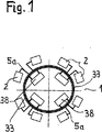
図1に示す装置は、飲料工業用の、ボトルの形のPETからなる耐熱性中空本体7を製造するように構成されている。装置は本質的にある数のブロー成形ステーション2を含み、ブロー成形ステーション2内において、中空本体7がブロー成形金型2a内に埋め込まれ且つ過圧が加えられ、これにより中空本体7はボトルに成形される。装置は、さらに、ブロー成形ステーション2ごとにそれぞれ主吹込空気配管5aを含み、主吹込空気配管5aは洗浄/冷却空気媒体貯槽33に接続されている。ブロー成形車の内部に均圧タンク38が存在し、均圧タンクの役目は、媒体貯槽31−36の圧力レベルをできるだけ一定に保持することである。媒体貯槽31−36は、図1の装置においては、リング・チャネルとして形成されている。
The apparatus shown in FIG. 1 is configured to produce a heat resistant
図2−4により、本発明の具体的な実施形態のプロセス経過を以下に説明する。中央プロセス媒体供給装置5が存在し、中央プロセス媒体供給装置5は、使用圧力のプロセス媒体を定置部分から回転分配装置70を介して機械の回転部分に供給する。ここで、各部分工程に対して圧縮空気が使用され、圧縮空気の圧力は機械の回転部分への供給において40バール(40×105パスカル)である。この空気は、洗浄/冷却空気媒体貯槽33内に、これが充満されるまで供給される。中央プロセス媒体供給装置5から仕上吹込媒体貯槽31への接続配管5bが存在し、接続配管5bは自動逆止弁57により制御される。機械の運転中に仕上吹込媒体貯槽31内の圧力がその目標値から約10%低下したとき、自動逆止弁57が開放し、且つ仕上吹込媒体貯槽31に接続配管5bを介してプロセス媒体供給装置5から空気が供給され、仕上吹込媒体貯槽31内の圧力が再びたかだか目標値以下10%の圧力が存在するまでの間供給される。このケースは、例えば機械の始動時に、媒体貯槽31−36内に過圧がまだ形成されていないときに発生する。これにより、仕上吹込媒体貯槽31には、仕上運転の前に予め、プロセス空気が供給される。自動逆止弁58、59a、59bおよび接続配管5g、5hおよび5iを介して、仕上吹込媒体貯槽31から、制御空気媒体貯槽34、「延伸棒上方」媒体貯槽35および「延伸棒下方」媒体貯槽36に圧縮空気が供給される。自動逆止弁58は、この場合、約10バール(10×105パスカル)の値に設定され、これにより制御空気媒体貯槽内にこの圧力を設定可能である。「延伸棒上方」媒体貯槽35および「延伸棒下方」媒体貯槽36は約6バール(6×105パスカル)の圧力のプロセス空気で充満されている。したがって、自動逆止弁59aおよび59bは約6バール(6×105パスカル)に設定されるだけでよい。
The process progress of a specific embodiment of the present invention will be described below with reference to FIGS. There is a central process
予備ブロー成形のためのプロセス空気を提供する予備吹込媒体貯槽32にもまた、自動逆止弁56および接続配管5eを介して圧縮空気が供給される。予備ブロー成形圧力は約5バール(5×10⁵パスカル)の値であるので、自動逆止弁56もまたほぼこの圧力に設定されている。
Compressed air is also supplied to the preliminary blowing
図2はさらにブロー成形ステーション2を示す。ブロー成形ステーション2は、弁ブロック50、吹込ノズル60、ブロー成形金型2aおよび中空延伸棒6からなっている。一方、弁ブロック50は、プロセス空気の流入ないしは流出を制御する弁51−55からなっている。吹込ノズル60は中空本体7の上部に装着され且つ接続配管5dおよび5kを介して弁ブロック50と接続されている。機械の運転時に閉鎖された金型2aと、およびブロー成形されるべき中空本体7との中に挿入される中空延伸棒6は、主吹込空気配管5aを介して洗浄/冷却空気媒体貯槽33と接続されている。
FIG. 2 further shows a
媒体貯槽31−36の全てが充満されているとき、中空本体7の本来の製造プロセスが開始可能である。
はじめに、ブロー成形されるべき中空本体7が金型2a内に挿入され、次に金型2aが閉鎖される。吹込ノズル60が中空本体7の上部に装着されたのち、中空本体7を縦方向に延伸させるために、中空延伸棒6が中空本体7内に上から挿入可能である。その直後に弁ブロック50内の弁51が開放され(図3、点81参照)、これにより、約5バール(5×105パスカル)の予備吹込空気を、接続配管5fおよび5dを介して吹込ノズル60の供給通路61内に、したがって中空本体7内に導くことが可能である。このとき、中空本体7は、ブロー成形金型壁の方向へ、半径方向にも延伸される。予備ブロー成形が終了したとき、弁51が再び閉鎖され且つ仕上吹込弁52が開放される(図3、点82参照)。これにより、約30バール(30×105パスカル)の圧力の仕上吹込空気が、仕上吹込媒体貯槽31から、接続配管5c、5dおよび吹込ノズル60の空気通路61を介して中空本体7内に流入する。ここでほぼ仕上げられた中空本体7内に圧力が形成されたとき、仕上ブロー成形工程が終了し、且つ仕上吹込弁52が再び閉鎖される。この工程時点において、中空本体は確かにその最終外側形状を既にほぼ達成しているが、その輪郭はなお完全には型付けされていない。このために、型付け工程が行われ、型付け工程は、洗浄/冷却空気弁53の開放(図3、点83参照)により開始される。これにより、約40バール(40×105パスカル)の圧力の低温洗浄空気が、洗浄/冷却空気媒体貯槽33から、接続配管5aおよび中空延伸棒6を介して中空本体7内に流入する。中空本体7内に圧力が形成された(図3、点83a参照)のち、中空本体7を完全に型付けするために、中空本体7はさらに少しの時間このレベルに保持される。洗浄空気のボトル内壁に対する温度差により、洗浄空気は多少加熱され且つボトル内壁はより低温となる。しかしながら、この時点において既に中空本体7をブロー成形金型2aから取り出そうとする場合、中空本体7は、なお含んでいる残留熱のためにきわめて不安定であろう。この理由から、中空本体7はさらに冷却されなければならない。このために、洗浄/冷却空気弁53がなお開放されたまま、仕上吹込弁52が改めて開放される(図3、点83b参照)。これにより、中空本体7内に存在するやや加熱された洗浄空気が、吹込ノズル60内の空気通路61および接続配管5dおよび5cを介して仕上吹込媒体貯槽31内に逆流可能である。この状態もまた、一方で中空本体7を冷却するために中空本体7内に必要な空気循環を発生させるために、他方で仕上吹込媒体貯槽31にプロセス空気を供給するために、少しの時間保持され、これにより、次のブロー成形ステップのために十分な圧縮空気が供給される。このプロセス・ステップにおいて、均圧により、中空本体7内に約30バール(30×105パスカル)の圧力が設定される(図3、点83c参照)。同時に空気リサイクル工程としても働くこの冷却/洗浄工程が終了したとき、仕上吹込弁52および洗浄/冷却空気弁53が閉鎖され、一方同時に圧抜き弁55が開放され(図3、点84参照)、これにより、中空本体7内に存在するプロセス空気が、吹込ノズル60の空気通路62、接続配管5kおよび接続配管5lを介して消音器65内に流入可能である(圧抜き工程)。これにより、圧抜き弁55の開放後においては中空本体7内にほぼ周囲条件が支配している。
When all of the medium reservoirs 31-36 are full, the original manufacturing process of the
First, the
しかしながら、洗浄/冷却工程ないしはリサイクリング工程後の圧抜きが、消音器65の方向ではなく、作業空気媒体貯槽37の方向に行われてもよい。このために、仕上吹込弁52および洗浄/冷却空気弁53が閉鎖されるのと同時に作業空気弁54が開放され(図3、点84参照)、これにより、中空本体7内の約30バール(30×105パスカル)の圧力の空気が、吹込ノズル60内の空気通路62および接続配管5kおよび5mを介して、作業空気媒体貯槽37内に流入可能である。作業空気媒体貯槽37から、接続配管5nおよび回転分配装置70を介して、空気を機械の回転部分から定置部分内に導入することが可能であり、これにより、機械の周辺内において行われる他のプロセスにプロセス空気を供給することが可能である。図示の実施形態においては、作業空気媒体貯槽37は機械の回転部分内に存在する。しかしながら、作業空気媒体貯槽37を定置部分または機械の外側に設置することもまた可能である。この場合には、空気は、圧抜き工程において、接続配管5mないしは5nを介して直接機械の回転分配装置70内に、したがって定置部分内に導かれるであろう。
However, the depressurization after the cleaning / cooling process or the recycling process may be performed not in the direction of the silencer 65 but in the direction of the working air
上記のようにプロセス空気が直ちに消音器65を介して圧抜きされないで、プロセス空気が作業空気媒体貯槽37を介して機械から導かれる場合、圧抜きは作業空気媒体貯槽37内に予めかかっている圧力レベルに至るまで行われるにすぎない。中空本体7内に存在する残留空気は回収されることなく、吹込ノズル60内の空気通路62、接続配管5kおよび5lを介して、および消音器65を介して大気中に導かれる。このために、中空本体7内の圧力と作業空気媒体貯槽37内の圧力とが同じになったのちに、作業空気弁54が閉鎖され且つ圧抜き弁55が開放される。
If the process air is not immediately depressurized via the silencer 65 as described above and the process air is guided from the machine via the working
プロセス空気流量を増大し、したがって機械の処理能力も向上させるために、弁ブロック50内の弁は異なって形成されていてもよい。断面が拡大されることにより1つの弁を通過する最大可能空気流量が上昇されても、または1つの切換点に複数の弁が設けられてもよい。即ち、例えば、圧抜きにおいて、1つの圧抜き弁55の代わりに、2つの圧抜き弁55および55′が使用されてもよい。
The valves in the
図3および図4は、機械位置(°)に関する吹込圧力(バール)を表わした工程線図と、および機械位置(°)に関する弁51−55′の切換線図とを示す。
工程の開始(機械位置0°)においては、予備吹込弁51、仕上吹込弁52および洗浄/冷却空気弁53は閉鎖され、圧抜き弁55および55′は開放されている。ある時間tののちに、予備吹込弁51の開放により予備ブロー成形過程がスタートされる(機械位置54°)。これにより、約5バール(5×105パスカル)の予備吹込空気が予備吹込媒体貯槽32から中空本体7内に搬送される。ほぼ同時に、圧抜き弁55および55′もまた閉鎖される。予備ブロー成形過程が終了したのち、予備吹込弁51が再び閉鎖され且つ仕上吹込弁52が開放される(機械位置64°)。仕上吹込弁52の閉鎖後に洗浄/冷却空気弁53が開放される(機械位置100°)。
3 and 4 show a process diagram representing the blowing pressure (bar) with respect to the machine position (°) and a switching diagram of the valves 51-55 ′ with respect to the machine position (°).
At the start of the process (
中空本体7の型付けが完了したとき、仕上吹込弁52が再度開放され(図3、点83b参照)、これにより、ここで、圧縮空気が、洗浄/冷却空気媒体貯槽33から、ブロー成形ステーション2を介して仕上吹込媒体貯槽31内に流入可能である(機械位置197°)。即ち、工程のこの時点においては、仕上吹込弁52および洗浄/冷却空気弁53は開放されている。仕上ブロー成形されたボトルが十分に冷却されたとき、仕上吹込弁52および洗浄/冷却空気弁53が閉鎖され、並びに圧抜き弁55および55′が開放され(図3、点84参照)、これにより、ボトル内に存在する約30バール(30×105パスカル)の圧縮空気は、圧抜き弁55、55′および消音器65を介して周囲に放出され、したがって、中空本体7内にはほぼ周囲条件が支配している(機械位置292°)。さらにブロー成形されるべき新たな中空本体7が再びブロー成形金型2a内に挿入されるまでの残りの工程時間(機械位置回転の68°)は、ブロー成形が完了したボトルの圧抜きおよびブロー成形金型2aの開放のために必要とされる。
When the molding of the
Claims (21)
次のステップ、即ち、
a)中空本体(7)を延伸し、および第1の媒体貯槽(32)内に貯蔵され且つ圧力p1の媒体をパリソン内に導入するステップ(予備ブロー成形工程)と、
b)第2の媒体貯槽(31)内に貯蔵され且つp1より高い圧力p2の第2の媒体を中空本体(7)内に導入するステップ(仕上ブロー成形工程)と、
c)第3の媒体貯槽(33)内に貯蔵され且つp2より高い圧力p3の第3の媒体を供給することにより中空本体(7)を内部から冷却するステップ(冷却工程)、および圧力差による結果として中空本体(7)を完全に型付けするステップ(型付け工程)と、
d)中空本体(7)を介して、第3の媒体貯槽(33)と、より低い圧力の媒体貯槽(31、32、34、35、36)との間の接続を形成し、およびこの結果として中空本体(7)の内部を冷却するステップ(洗浄工程)と、
e)この接続を切り離し、および中空本体(7)内にほぼ周囲圧力がかかるように中空本体(7)から媒体を排出するステップ(圧抜き工程)と、
を少なくとも有する、中空本体の製造方法。In the method for producing a hollow body (7) molded from a heated parison made of thermoplastic plastic in a blow mold (2a) having a contour,
The next step, namely
a) stretching the hollow body (7) and introducing a medium stored in the first medium reservoir (32) and having a pressure p1 into the parison (pre-blow molding process);
b) introducing a second medium stored in the second medium storage tank (31) and having a pressure p2 higher than p1 into the hollow body (7) (finish blow molding process);
c) a step of cooling the hollow body (7) from the inside by supplying a third medium stored in the third medium storage tank (33) and having a pressure p3 higher than p2 (cooling step), and a pressure difference As a result, the step of completely molding the hollow body (7) (molding process);
d) Forming a connection between the third medium reservoir (33) and the lower pressure medium reservoir (31, 32, 34, 35, 36) via the hollow body (7) and the result Cooling the inside of the hollow body (7) as (cleaning step),
e) disconnecting this connection and discharging the medium from the hollow body (7) so that a substantially ambient pressure is applied in the hollow body (7) (pressure relief process);
A method for producing a hollow body having at least
中空本体(7)が、輪郭を有するブロー成形金型(2a)内において、熱可塑性プラスチックからなる加熱されたパリソンから、第1の媒体貯槽(32)内に貯蔵され且つ圧力p1の予備吹込媒体をパリソン(7)内に導入すること(予備ブロー成形工程)により、およびほぼ同時に延伸棒(6)によって中空本体(7)を延伸し、および第2の媒体貯槽(31)内に貯蔵され且つp1より高い圧力p2の仕上吹込媒体を中空本体(7)内に導入すること(仕上ブロー成形工程)により成形され、および、中空本体(7)が、第3の媒体貯槽(33)内に貯蔵されている圧力p2より高い圧力p3の冷却媒体によって冷却される(冷却及び型付け工程)ように構成した、中空本体(7)の製造装置において、
予備吹込媒体の圧力が2−20バール(2×10⁵―20×105パスカル)であり、仕上吹込媒体の圧力が15−45バール(15×105―45×105パスカル)であり、および冷却媒体の圧力が30−45バール(30×105―45×105パスカル)であり、
前記冷却及び型付け工程の後に、前記中空本体(7)を介して、第3の媒体貯槽(33)と、より低い圧力の媒体貯槽(31、32、34、35、36)との間の接続を形成し、およびこの結果として中空本体(7)の内部を冷却すること(洗浄工程)を特徴とする中空本体の製造装置。An apparatus for manufacturing a hollow body (7),
A hollow body (7) is stored in a first medium reservoir (32) from a heated parison made of thermoplastic plastic in a blow mold (2a) having a contour and a pre-injection medium at pressure p1 Is drawn into the parison (7) (pre-blow molding step), and at about the same time, the hollow body (7) is stretched by the stretch rod (6) and stored in the second medium reservoir (31) and It is formed by introducing a finish blowing medium having a pressure p2 higher than p1 into the hollow body (7) (finish blow molding step), and the hollow body (7) is stored in the third medium storage tank (33). In the manufacturing apparatus of the hollow body (7) configured to be cooled by a cooling medium having a pressure p3 higher than the pressure p2 being applied ( cooling and shaping step ),
The pressure of the preliminary blowing medium is 2-20 bar (2 × 10 5 -20 × 10 5 Pascal), the pressure of the finishing blowing medium is 15-45 bar (15 × 10 5 -45 × 10 5 Pascal), and the pressure of the cooling medium is Ri 30-45 bar (30 × 10 5 -45 × 10 5 pascals) der,
Connection between the third medium reservoir (33) and the lower pressure medium reservoir (31, 32, 34, 35, 36) via the hollow body (7) after the cooling and shaping step And, as a result, the inside of the hollow body (7) is cooled (cleaning step) .
Applications Claiming Priority (2)
| Application Number | Priority Date | Filing Date | Title |
|---|---|---|---|
| DE102004014653.5A DE102004014653B4 (en) | 2004-03-25 | 2004-03-25 | Process and device for producing a particularly heat-resistant hollow body |
| PCT/EP2005/002399 WO2005092594A1 (en) | 2004-03-25 | 2005-03-08 | Method and device for producing a hollow body while reducing air consumption |
Publications (2)
| Publication Number | Publication Date |
|---|---|
| JP2007530314A JP2007530314A (en) | 2007-11-01 |
| JP4550109B2 true JP4550109B2 (en) | 2010-09-22 |
Family
ID=34961018
Family Applications (1)
| Application Number | Title | Priority Date | Filing Date |
|---|---|---|---|
| JP2007504285A Active JP4550109B2 (en) | 2004-03-25 | 2005-03-08 | Hollow body manufacturing method and apparatus for reducing air consumption |
Country Status (8)
| Country | Link |
|---|---|
| US (3) | US7892477B2 (en) |
| EP (1) | EP1727661B2 (en) |
| JP (1) | JP4550109B2 (en) |
| CN (1) | CN100540272C (en) |
| AT (1) | ATE442239T1 (en) |
| DE (5) | DE202004021781U1 (en) |
| ES (1) | ES2331368T5 (en) |
| WO (1) | WO2005092594A1 (en) |
Families Citing this family (59)
| Publication number | Priority date | Publication date | Assignee | Title |
|---|---|---|---|---|
| EP1660301B2 (en) | 2003-09-05 | 2021-06-16 | KHS Corpoplast GmbH | Method and device for blow-forming containers |
| DE202004021781U1 (en) * | 2004-03-25 | 2010-12-09 | Krones Ag | Device for producing a particular heat-resistant hollow body |
| FR2889993B1 (en) * | 2005-08-23 | 2007-12-28 | Technoplan Engineering S A Sa | PROCESS FOR BLOWING BY MEANS OF A GAS OF A PACKAGING AND INSTALLATION FOR CARRYING OUT SAID METHOD |
| GB2431372A (en) * | 2005-10-18 | 2007-04-25 | Ebac Ltd | Apparatus and method for blow moulding articles |
| ITRM20060001A1 (en) * | 2006-01-04 | 2007-07-05 | Sipa Societa Industrializzazione | PROCESS AND PRODUCTION PLANT FOR BLOWING PLASTIC CONTAINERS |
| ITTV20060169A1 (en) * | 2006-09-26 | 2008-03-27 | Acqua Minerale San Benedetto Spa | APPARATUS FOR BLOWING CONTAINERS IN PLASTIC MATERIAL WITH RECOVERY OF THE COMPRESSED BLOWING GAS AND ITS OPERATING METHOD |
| DE102006054268A1 (en) * | 2006-11-17 | 2008-05-21 | Veritas Ag | Tubular shaped part |
| DE102007015105B4 (en) | 2007-03-29 | 2022-03-10 | Krones Aktiengesellschaft | Blow molding device |
| ITRM20070370A1 (en) * | 2007-07-03 | 2009-01-04 | Sipa Societa Industrializzazio | MOLDING MACHINE FOR CONTAINER BLOWING |
| FR2920692B1 (en) * | 2007-09-10 | 2010-02-26 | Sidel Participations | METHOD FOR FORMING CONTAINERS COMPRISING A SCAN STAGE OF THE INTERNAL VOLUME OF THE RECIPIENT HAVING A VARIABLE DURATION OVER AT LEAST ONE TIME OF COMPENSATION GIVEN |
| FR2921293B1 (en) * | 2007-09-24 | 2012-11-02 | Sidel Participations | PROCESS FOR MANUFACTURING CONTAINERS COMPRISING AN INTERMEDIATE DEPRESSURIZATION OPERATION |
| DE202008005257U1 (en) | 2008-04-17 | 2008-11-20 | Krones Ag | Device for blow molding |
| EP2143545A1 (en) * | 2008-07-07 | 2010-01-13 | Nestec S.A. | Method and apparatus for packaging a liquid food product |
| DE102008061492A1 (en) | 2008-12-10 | 2010-06-17 | Krones Ag | Method and device for the economical production of plastic containers |
| DE102009011583A1 (en) * | 2009-03-06 | 2010-09-09 | Krones Ag | Method and device for producing and filling thin-walled beverage containers |
| DE102009031154A1 (en) * | 2009-06-30 | 2011-01-05 | Krones Ag | Method for converting a blow molding machine and blow molding machine |
| CN101612787B (en) * | 2009-07-14 | 2011-07-27 | 亚普汽车部件有限公司 | Manufacturing method of plastic fuel tank |
| DE102009041013A1 (en) * | 2009-09-10 | 2011-03-24 | Krones Ag | Method and apparatus for blow molding containers |
| DE102009044258A1 (en) * | 2009-10-15 | 2011-05-05 | Krones Ag | Plant and process for the production, filling, packaging and / or transport of beverages |
| DE102009060654B4 (en) * | 2009-12-22 | 2019-05-16 | Krones Aktiengesellschaft | Method and device for producing plastic bottles |
| DE102010007542A1 (en) | 2010-02-08 | 2011-08-11 | KHS Corpoplast GmbH, 22145 | Method and apparatus for blow molding containers |
| FR2962931B1 (en) | 2010-07-20 | 2014-02-14 | Sidel Participations | DEVICE FOR INJECTING AT LEAST TWO PRESSURIZED FLUIDS INTO THE COLLAR OF A CONTAINER FOR FORMING SUCH A CONTAINER |
| JP5725643B2 (en) * | 2010-10-14 | 2015-05-27 | 日精エー・エス・ビー機械株式会社 | Operation method of blow molding equipment |
| DE102011101259A1 (en) | 2011-05-11 | 2012-11-15 | Krones Aktiengesellschaft | Apparatus and method for forming plastic preforms |
| US9044887B2 (en) * | 2011-05-27 | 2015-06-02 | Discma Ag | Method of forming a container |
| DE102011106652A1 (en) | 2011-07-05 | 2013-01-10 | Krones Aktiengesellschaft | Blowing machine with pressure cylinder with force compensation for piston compressor |
| FR2978371B1 (en) * | 2011-07-25 | 2013-08-16 | Sidel Participations | "DEVICE FOR INJECTING A PRESSURIZED LIQUID FOR FORMING A CONTAINER COMPRISING A WORKING CHAMBER AGAINST PUSHING PUMPING MEANS" |
| BR112014002887B1 (en) * | 2011-08-08 | 2020-09-15 | Discma Ag | ROTATING SYSTEM FOR SIMULTANEOUSLY BLOWING AND FILLING PLASTIC CONTAINERS |
| EP2607052A1 (en) | 2011-12-21 | 2013-06-26 | Nestec S.A. | A method and system for blowing and filling lightweight containers |
| DE102012025788B3 (en) | 2012-04-17 | 2023-12-28 | Krones Aktiengesellschaft | Device and method for expanding plastic containers |
| DE102012103349A1 (en) * | 2012-04-17 | 2013-10-17 | Krones Ag | Blow molding machine with bottom cooling in stabilization phase |
| FR2991227B1 (en) | 2012-05-30 | 2014-07-04 | Sidel Participations | PROCESS FOR MANUFACTURING A CONTAINER FROM A BLANK, WITH FEEDBACK ACCORDING TO REAL PRESSURE OF END OF PRESSURE |
| DE102012106916A1 (en) * | 2012-07-30 | 2014-05-22 | Krones Ag | Apparatus and method for forming plastic preforms with separate flow paths for blowing air and control air |
| JP6072250B2 (en) | 2012-08-03 | 2017-02-01 | 株式会社吉野工業所 | Method and apparatus for manufacturing containers |
| DE102012110023A1 (en) * | 2012-10-19 | 2014-04-24 | Krones Ag | Blowing machine with variable intermediate pressure level |
| JP6028521B2 (en) * | 2012-10-25 | 2016-11-16 | 東洋製罐株式会社 | Blow molding apparatus and blow molding method |
| DE102013104995A1 (en) * | 2013-05-15 | 2014-11-20 | Krones Ag | Blow molding machine with separate pressure pad control |
| JP6496720B2 (en) * | 2013-06-24 | 2019-04-03 | ディスクマ アーゲーDiscma Ag | Method and station for forming a container by applying a pressure profile controlled by an extension rod and machine comprising the station |
| WO2014209341A1 (en) | 2013-06-28 | 2014-12-31 | Discma Ag | Method of molding a container |
| FR3023743B1 (en) | 2014-07-18 | 2016-07-29 | Sidel Participations | METHOD FOR DETECTING ANOMALIES IN A CONTAINER FORMING MACHINE |
| EP2987604B1 (en) * | 2014-08-20 | 2016-11-16 | Krones AG | Device and method for vacuum recycling in a container treatment system |
| EP2987606B1 (en) * | 2014-08-20 | 2020-03-18 | Krones AG | Method for de-moulding and filling containers and mould filling machine |
| JP6448381B2 (en) * | 2015-01-19 | 2019-01-09 | サントリーホールディングス株式会社 | Compressed air supply system |
| DE102015106615A1 (en) * | 2015-04-29 | 2016-11-03 | Krones Ag | Method and device for forming plastic preforms with container cooling |
| DE102015211131A1 (en) * | 2015-06-17 | 2016-12-22 | Krones Ag | Method and blow molding machine for molding and filling containers |
| CN107571480B (en) | 2016-07-04 | 2020-11-06 | 边宇弘 | Method for manufacturing pressure container with in-mold label and three-dimensional shape |
| DE102016125552A1 (en) | 2016-12-23 | 2018-06-28 | Krones Ag | Method and device for blow molding containers with movable bottom part |
| DE102016125586A1 (en) | 2016-12-23 | 2018-06-28 | Krones Aktiengesellschaft | Method and device for blow molding containers with movable bottom part |
| DE102017120863A1 (en) * | 2017-09-10 | 2019-03-14 | Khs Corpoplast Gmbh | Method and device for producing containers made of thermoplastic material |
| FR3080795B1 (en) | 2018-05-02 | 2020-04-03 | Sidel Participations | METHOD OF FORMING CONTAINER IN THERMOPLASTIC MATERIAL BY BI-AXIAL DRAWING |
| CN109483854A (en) * | 2018-12-31 | 2019-03-19 | 宁波新博来万机械有限公司 | A kind of novel hot tank bottle blowing machine |
| CN114650906A (en) * | 2019-09-20 | 2022-06-21 | 日精Asb机械株式会社 | Blow molding apparatus and blow molding method for resin container |
| KR102193067B1 (en) * | 2020-01-02 | 2020-12-18 | 최주영 | Method for manufacturing a double container having a replaceable inner container inside the outer container |
| DE102020115854A1 (en) | 2020-06-16 | 2021-12-16 | Khs Corpoplast Gmbh | Method for producing containers from preforms by means of a device for producing containers |
| DE102020116537A1 (en) * | 2020-06-23 | 2021-12-23 | Khs Corpoplast Gmbh | Method and apparatus for producing containers from thermally conditioned preforms made of thermoplastic material |
| DE102021127436A1 (en) * | 2021-10-21 | 2023-04-27 | Krones Aktiengesellschaft | Process and device for blow molding containers with a movable base |
| DE102021128205A1 (en) | 2021-10-28 | 2023-05-04 | Krones Aktiengesellschaft | Device and method for forming plastic preforms into plastic containers with an adjustable throttle |
| DE102022122880A1 (en) | 2022-09-08 | 2024-03-14 | Krones Aktiengesellschaft | Method and device for forming plastic preforms into plastic containers with controlled reservoir pressure |
| DE102022122881A1 (en) * | 2022-09-08 | 2024-03-14 | Krones Aktiengesellschaft | Method and device for forming plastic preforms into plastic containers with machine control |
Family Cites Families (49)
| Publication number | Priority date | Publication date | Assignee | Title |
|---|---|---|---|---|
| GB763584A (en) * | 1951-12-17 | 1956-12-12 | Francis Trigg Parfrey | A new and improved method of and means for forming hollow articles from thermo-plastic material by blowing |
| US3247304A (en) * | 1961-10-17 | 1966-04-19 | Owens Illinois Glass Co | Method of and apparatus for making plastic articles |
| US3339229A (en) * | 1964-12-09 | 1967-09-05 | Dow Chemical Co | Plastic bottle blowing and reaming apparatus |
| DE1993432U (en) * | 1968-06-21 | 1968-09-05 | Fritz Wessolleck | TOY. |
| US3717429A (en) * | 1971-01-04 | 1973-02-20 | Phillips Petroleum Co | Apparatus for cooling the blow pin and plastic molding material during blow molding operation |
| US3806300A (en) * | 1971-05-27 | 1974-04-23 | Ethyl Dev Corp | Apparatus for forming the neck on a plastic container |
| US3819317A (en) * | 1972-10-30 | 1974-06-25 | Haskon Inc | Apparatus for blow molding and injecting cooling gas |
| US4043735A (en) * | 1973-11-28 | 1977-08-23 | Farrell Patent Company | Balloon blow molding tooling |
| CH602308A5 (en) * | 1975-02-20 | 1978-07-31 | Paul Marcus | |
| US3977822A (en) * | 1975-03-17 | 1976-08-31 | Monsanto Company | Apparatus for continuous stretch-blow molding |
| BE845899A (en) * | 1976-05-24 | 1976-12-31 | APPARATUS FOR CONTROL OF THE DISTRIBUTION OF PLASTIC MATERIAL DURING THE MANUFACTURING OF PLASTIC CONTAINERS WITH BI-AXIAL ORIENTATION | |
| US4070141A (en) * | 1976-11-26 | 1978-01-24 | Leonard Benoit Ryder | Apparatus for injection blow molding |
| US4065535A (en) * | 1976-12-27 | 1977-12-27 | Hercules Incorporated | Thread forming and neck finishing process |
| US4473515A (en) | 1980-09-02 | 1984-09-25 | Ryder Leonard B | Injection blow molding method |
| US4488863A (en) * | 1981-02-23 | 1984-12-18 | The Continental Group, Inc. | Recycling of blow air |
| US4379688A (en) * | 1981-09-14 | 1983-04-12 | Ethyl Development Corporation | Oriented injection blow molded container production |
| SE448967B (en) * | 1983-03-10 | 1987-03-30 | Petainer Sa | SET AND DEVICE FOR MANUFACTURING THERMOPLASTIC CONTAINERS |
| US4549865A (en) * | 1984-03-28 | 1985-10-29 | Owens-Illinois, Inc. | Blow molding apparatus |
| US4883631A (en) * | 1986-09-22 | 1989-11-28 | Owens-Illinois Plastic Products Inc. | Heat set method for oval containers |
| JPH039831A (en) | 1989-06-06 | 1991-01-17 | Mitsubishi Plastics Ind Ltd | Manufacture of blow molded container |
| US5136333A (en) † | 1989-06-30 | 1992-08-04 | Lexmark International, Inc. | Electrophotographic printer and cartridge arrangement |
| JPH0647269B2 (en) * | 1989-08-31 | 1994-06-22 | 日精エー・エス・ビー機械株式会社 | Method and apparatus for molding heat-resistant hollow container |
| US5182122A (en) | 1989-08-31 | 1993-01-26 | Nissei Asb Machine Co., Ltd. | Apparatus for stretch blow molding hollow heat-resistant container |
| JP3153907B2 (en) | 1990-12-18 | 2001-04-09 | 弘料 吉岡 | Gas compression recycling equipment |
| US5290506A (en) * | 1991-04-30 | 1994-03-01 | Nissei Asb Machine Co., Ltd. | Process of injection stretch blow molding hollow article having thick-walled bottom |
| JP3054233B2 (en) | 1991-05-31 | 2000-06-19 | 三菱樹脂株式会社 | Blow molding bottle manufacturing method |
| DE4425518C2 (en) | 1993-07-29 | 1996-06-05 | Air Prod Gmbh | Process for the cryogenic production of blow molded parts made of plastic |
| US5474735A (en) * | 1993-09-24 | 1995-12-12 | Continental Pet Technologies, Inc. | Pulse blow method for forming container with enhanced thermal stability |
| DE4340291A1 (en) | 1993-11-26 | 1995-06-01 | Krupp Corpoplast Masch | Multiple use of blown air |
| DE4340290A1 (en) * | 1993-11-26 | 1995-06-01 | Krupp Corpoplast Masch | Multiple use of working air |
| JPH07156259A (en) | 1993-12-03 | 1995-06-20 | Denki Kagaku Kogyo Kk | Manufacture of resin hollow vessel |
| TW289008B (en) * | 1995-07-18 | 1996-10-21 | A K Tech Lab Inc | Air operation method and device for an extention blow forming machine |
| JPH11227035A (en) | 1997-04-11 | 1999-08-24 | Boc Group Inc:The | Cooling of article in heated mold of blow drawing molding apparatus of single mold |
| JP3801766B2 (en) | 1998-01-27 | 2006-07-26 | 株式会社吉野工業所 | How to collect blowers |
| US6428735B1 (en) | 1999-02-26 | 2002-08-06 | Schmalbach-Lubeca Ag | Method for making a carbonated soft drink bottle with an internal web and hand-grip feature |
| DE19934320A1 (en) * | 1999-07-21 | 2001-01-25 | Krupp Corpoplast Maschb Gmbh | Rapid blow molding of e.g. PET bottles, employs air hotter than blowing mold to prevent plastic surface degradation and monomer deposits, with additional refinements assuring excellent upright stability and appearance |
| US6485669B1 (en) | 1999-09-14 | 2002-11-26 | Schmalbach-Lubeca Ag | Blow molding method for producing pasteurizable containers |
| US6514451B1 (en) | 2000-06-30 | 2003-02-04 | Schmalbach-Lubeca Ag | Method for producing plastic containers having high crystallinity bases |
| US6733716B2 (en) † | 2001-05-21 | 2004-05-11 | Sabel Plastechs Inc. | Method of making a stretch/blow molded article (bottle) with an integral projection such as a handle |
| FR2827541B1 (en) * | 2001-07-20 | 2005-07-01 | Technoplan Engineering S A | DEVICE FOR BLOWING PACKAGES |
| GB2380967B (en) * | 2001-09-28 | 2003-12-24 | Roton Compressor Services Ltd | Blow moulding control system |
| US6855289B2 (en) * | 2001-11-27 | 2005-02-15 | Graham Packaging Pet Technologies, Inc. | Method and apparatus for cooling during in-mold handle attachment |
| DE10340915A1 (en) * | 2003-09-05 | 2005-03-31 | Sig Technology Ltd. | Method and device for blow-molding workpieces |
| DE202004021781U1 (en) * | 2004-03-25 | 2010-12-09 | Krones Ag | Device for producing a particular heat-resistant hollow body |
| KR101199692B1 (en) * | 2004-07-27 | 2012-11-08 | 도요 세이칸 가부시키가이샤 | Polyester container having excellent heat resistance and shock resistance and method of producing the same |
| EP1778780B1 (en) * | 2004-08-18 | 2009-01-14 | Basell Poliolefine Italia S.r.l. | Stretch blow-molded containers from ziegler natta propylene polymer compositions |
| FR2920692B1 (en) * | 2007-09-10 | 2010-02-26 | Sidel Participations | METHOD FOR FORMING CONTAINERS COMPRISING A SCAN STAGE OF THE INTERNAL VOLUME OF THE RECIPIENT HAVING A VARIABLE DURATION OVER AT LEAST ONE TIME OF COMPENSATION GIVEN |
| DE102009035868A1 (en) * | 2009-07-31 | 2011-02-03 | Krones Ag | Device for forming plastic preforms with synchronous heating and stretching |
| GB201008520D0 (en) * | 2010-05-21 | 2010-07-07 | Brittpac Ltd | Containers |
-
2004
- 2004-03-25 DE DE202004021781U patent/DE202004021781U1/en not_active Expired - Lifetime
- 2004-03-25 DE DE202004021780U patent/DE202004021780U1/en not_active Expired - Lifetime
- 2004-03-25 DE DE102004014653.5A patent/DE102004014653B4/en not_active Expired - Fee Related
- 2004-03-25 DE DE202004021779U patent/DE202004021779U1/en not_active Expired - Lifetime
-
2005
- 2005-03-08 AT AT05707725T patent/ATE442239T1/en not_active IP Right Cessation
- 2005-03-08 WO PCT/EP2005/002399 patent/WO2005092594A1/en not_active Application Discontinuation
- 2005-03-08 CN CNB2005800096499A patent/CN100540272C/en active Active
- 2005-03-08 ES ES05707725T patent/ES2331368T5/en active Active
- 2005-03-08 US US10/592,821 patent/US7892477B2/en not_active Expired - Fee Related
- 2005-03-08 EP EP05707725.7A patent/EP1727661B2/en active Active
- 2005-03-08 DE DE502005008104T patent/DE502005008104D1/en active Active
- 2005-03-08 JP JP2007504285A patent/JP4550109B2/en active Active
-
2010
- 2010-12-23 US US12/978,062 patent/US8550805B2/en active Active
- 2010-12-23 US US12/978,047 patent/US9044892B2/en not_active Expired - Fee Related
Also Published As
| Publication number | Publication date |
|---|---|
| US9044892B2 (en) | 2015-06-02 |
| DE502005008104D1 (en) | 2009-10-22 |
| ATE442239T1 (en) | 2009-09-15 |
| JP2007530314A (en) | 2007-11-01 |
| DE202004021781U1 (en) | 2010-12-09 |
| US20110089613A1 (en) | 2011-04-21 |
| DE102004014653A1 (en) | 2005-10-13 |
| DE102004014653B4 (en) | 2022-10-20 |
| ES2331368T5 (en) | 2013-07-31 |
| EP1727661B2 (en) | 2013-05-08 |
| ES2331368T3 (en) | 2009-12-30 |
| DE202004021779U1 (en) | 2010-12-09 |
| US8550805B2 (en) | 2013-10-08 |
| EP1727661B1 (en) | 2009-09-09 |
| US20080164642A1 (en) | 2008-07-10 |
| CN100540272C (en) | 2009-09-16 |
| EP1727661A1 (en) | 2006-12-06 |
| US7892477B2 (en) | 2011-02-22 |
| WO2005092594A1 (en) | 2005-10-06 |
| DE202004021780U1 (en) | 2010-12-09 |
| CN1938145A (en) | 2007-03-28 |
| US20110089614A1 (en) | 2011-04-21 |
Similar Documents
| Publication | Publication Date | Title |
|---|---|---|
| JP4550109B2 (en) | Hollow body manufacturing method and apparatus for reducing air consumption | |
| CA2412364C (en) | Method and apparatus for cooling during in-mold handle attachment | |
| US9498913B2 (en) | Method and device for producing filled containers | |
| US10696434B2 (en) | Method and device for producing containers which are filled with a liquid filling substance | |
| US10350814B2 (en) | System for forming and filling containers with carbonated products at ambient temperature | |
| CN101934582A (en) | A kind of method and a kind of blow moulding machine that blow moulding machine is changed of being used for | |
| JP3953521B2 (en) | Improvement of method and equipment for manufacturing thermoplastic resin parison | |
| US10350816B2 (en) | Form-filing machine | |
| JP6770666B1 (en) | Resin container manufacturing equipment and manufacturing method | |
| CA3062869C (en) | Stretch blow molding apparatus and blow molding method | |
| JP2022188209A (en) | Method for manufacturing resin container, mold for temperature control and blow molding device | |
| CN108437411B (en) | Airflow type self-expansion forming bottle blowing device | |
| CN206551467U (en) | Device for plastic preforms to be molded into plastic containers | |
| JP5082900B2 (en) | Method for producing a synthetic resin container having handle pieces connected thereto | |
| WO2021060497A1 (en) | Method for producing resin container and device for producing resin container | |
| TWI699276B (en) | Method for manufacturing resin container and blow molding device | |
| JPWO2019208498A1 (en) | Injection molding dies, lip dies included in them, and injection molding methods | |
| MXPA98007591A (en) | Improvement in the method and plant to manufacture resin preforms termoplast |
Legal Events
| Date | Code | Title | Description |
|---|---|---|---|
| A621 | Written request for application examination |
Free format text: JAPANESE INTERMEDIATE CODE: A621 Effective date: 20071009 |
|
| A977 | Report on retrieval |
Free format text: JAPANESE INTERMEDIATE CODE: A971007 Effective date: 20091113 |
|
| A131 | Notification of reasons for refusal |
Free format text: JAPANESE INTERMEDIATE CODE: A131 Effective date: 20091118 |
|
| A521 | Request for written amendment filed |
Free format text: JAPANESE INTERMEDIATE CODE: A523 Effective date: 20100204 |
|
| A131 | Notification of reasons for refusal |
Free format text: JAPANESE INTERMEDIATE CODE: A131 Effective date: 20100329 |
|
| A521 | Request for written amendment filed |
Free format text: JAPANESE INTERMEDIATE CODE: A523 Effective date: 20100528 |
|
| TRDD | Decision of grant or rejection written | ||
| A01 | Written decision to grant a patent or to grant a registration (utility model) |
Free format text: JAPANESE INTERMEDIATE CODE: A01 Effective date: 20100623 |
|
| A01 | Written decision to grant a patent or to grant a registration (utility model) |
Free format text: JAPANESE INTERMEDIATE CODE: A01 |
|
| A61 | First payment of annual fees (during grant procedure) |
Free format text: JAPANESE INTERMEDIATE CODE: A61 Effective date: 20100707 |
|
| R150 | Certificate of patent or registration of utility model |
Ref document number: 4550109 Country of ref document: JP Free format text: JAPANESE INTERMEDIATE CODE: R150 Free format text: JAPANESE INTERMEDIATE CODE: R150 |
|
| FPAY | Renewal fee payment (event date is renewal date of database) |
Free format text: PAYMENT UNTIL: 20130716 Year of fee payment: 3 |
|
| R250 | Receipt of annual fees |
Free format text: JAPANESE INTERMEDIATE CODE: R250 |
|
| R250 | Receipt of annual fees |
Free format text: JAPANESE INTERMEDIATE CODE: R250 |
|
| R250 | Receipt of annual fees |
Free format text: JAPANESE INTERMEDIATE CODE: R250 |
|
| R250 | Receipt of annual fees |
Free format text: JAPANESE INTERMEDIATE CODE: R250 |
|
| R250 | Receipt of annual fees |
Free format text: JAPANESE INTERMEDIATE CODE: R250 |
|
| R250 | Receipt of annual fees |
Free format text: JAPANESE INTERMEDIATE CODE: R250 |
|
| R250 | Receipt of annual fees |
Free format text: JAPANESE INTERMEDIATE CODE: R250 |
|
| R250 | Receipt of annual fees |
Free format text: JAPANESE INTERMEDIATE CODE: R250 |
|
| R250 | Receipt of annual fees |
Free format text: JAPANESE INTERMEDIATE CODE: R250 |
|
| R250 | Receipt of annual fees |
Free format text: JAPANESE INTERMEDIATE CODE: R250 |
|
| R250 | Receipt of annual fees |
Free format text: JAPANESE INTERMEDIATE CODE: R250 |