JP4549596B2 - Device for regulating flow in a part or passage of a conduit and an intake manifold including the device - Google Patents
Device for regulating flow in a part or passage of a conduit and an intake manifold including the device Download PDFInfo
- Publication number
- JP4549596B2 JP4549596B2 JP2001519999A JP2001519999A JP4549596B2 JP 4549596 B2 JP4549596 B2 JP 4549596B2 JP 2001519999 A JP2001519999 A JP 2001519999A JP 2001519999 A JP2001519999 A JP 2001519999A JP 4549596 B2 JP4549596 B2 JP 4549596B2
- Authority
- JP
- Japan
- Prior art keywords
- manifold
- control shaft
- parts
- assembly
- bearing
- Prior art date
- Legal status (The legal status is an assumption and is not a legal conclusion. Google has not performed a legal analysis and makes no representation as to the accuracy of the status listed.)
- Expired - Fee Related
Links
Images


Classifications
-
- F—MECHANICAL ENGINEERING; LIGHTING; HEATING; WEAPONS; BLASTING
- F02—COMBUSTION ENGINES; HOT-GAS OR COMBUSTION-PRODUCT ENGINE PLANTS
- F02M—SUPPLYING COMBUSTION ENGINES IN GENERAL WITH COMBUSTIBLE MIXTURES OR CONSTITUENTS THEREOF
- F02M35/00—Combustion-air cleaners, air intakes, intake silencers, or induction systems specially adapted for, or arranged on, internal-combustion engines
- F02M35/10—Air intakes; Induction systems
- F02M35/104—Intake manifolds
- F02M35/108—Intake manifolds with primary and secondary intake passages
- F02M35/1085—Intake manifolds with primary and secondary intake passages the combustion chamber having multiple intake valves
-
- F—MECHANICAL ENGINEERING; LIGHTING; HEATING; WEAPONS; BLASTING
- F02—COMBUSTION ENGINES; HOT-GAS OR COMBUSTION-PRODUCT ENGINE PLANTS
- F02D—CONTROLLING COMBUSTION ENGINES
- F02D9/00—Controlling engines by throttling air or fuel-and-air induction conduits or exhaust conduits
- F02D9/08—Throttle valves specially adapted therefor; Arrangements of such valves in conduits
- F02D9/10—Throttle valves specially adapted therefor; Arrangements of such valves in conduits having pivotally-mounted flaps
- F02D9/109—Throttle valves specially adapted therefor; Arrangements of such valves in conduits having pivotally-mounted flaps having two or more flaps
- F02D9/1095—Rotating on a common axis, e.g. having a common shaft
-
- F—MECHANICAL ENGINEERING; LIGHTING; HEATING; WEAPONS; BLASTING
- F02—COMBUSTION ENGINES; HOT-GAS OR COMBUSTION-PRODUCT ENGINE PLANTS
- F02M—SUPPLYING COMBUSTION ENGINES IN GENERAL WITH COMBUSTIBLE MIXTURES OR CONSTITUENTS THEREOF
- F02M35/00—Combustion-air cleaners, air intakes, intake silencers, or induction systems specially adapted for, or arranged on, internal-combustion engines
- F02M35/10—Air intakes; Induction systems
- F02M35/10242—Devices or means connected to or integrated into air intakes; Air intakes combined with other engine or vehicle parts
- F02M35/10255—Arrangements of valves; Multi-way valves
-
- F—MECHANICAL ENGINEERING; LIGHTING; HEATING; WEAPONS; BLASTING
- F02—COMBUSTION ENGINES; HOT-GAS OR COMBUSTION-PRODUCT ENGINE PLANTS
- F02M—SUPPLYING COMBUSTION ENGINES IN GENERAL WITH COMBUSTIBLE MIXTURES OR CONSTITUENTS THEREOF
- F02M35/00—Combustion-air cleaners, air intakes, intake silencers, or induction systems specially adapted for, or arranged on, internal-combustion engines
- F02M35/10—Air intakes; Induction systems
- F02M35/10314—Materials for intake systems
- F02M35/10321—Plastics; Composites; Rubbers
-
- F—MECHANICAL ENGINEERING; LIGHTING; HEATING; WEAPONS; BLASTING
- F02—COMBUSTION ENGINES; HOT-GAS OR COMBUSTION-PRODUCT ENGINE PLANTS
- F02M—SUPPLYING COMBUSTION ENGINES IN GENERAL WITH COMBUSTIBLE MIXTURES OR CONSTITUENTS THEREOF
- F02M35/00—Combustion-air cleaners, air intakes, intake silencers, or induction systems specially adapted for, or arranged on, internal-combustion engines
- F02M35/10—Air intakes; Induction systems
- F02M35/1034—Manufacturing and assembling intake systems
- F02M35/10354—Joining multiple sections together
-
- F—MECHANICAL ENGINEERING; LIGHTING; HEATING; WEAPONS; BLASTING
- F02—COMBUSTION ENGINES; HOT-GAS OR COMBUSTION-PRODUCT ENGINE PLANTS
- F02D—CONTROLLING COMBUSTION ENGINES
- F02D9/00—Controlling engines by throttling air or fuel-and-air induction conduits or exhaust conduits
- F02D9/08—Throttle valves specially adapted therefor; Arrangements of such valves in conduits
- F02D9/10—Throttle valves specially adapted therefor; Arrangements of such valves in conduits having pivotally-mounted flaps
- F02D9/107—Manufacturing or mounting details
-
- F—MECHANICAL ENGINEERING; LIGHTING; HEATING; WEAPONS; BLASTING
- F02—COMBUSTION ENGINES; HOT-GAS OR COMBUSTION-PRODUCT ENGINE PLANTS
- F02M—SUPPLYING COMBUSTION ENGINES IN GENERAL WITH COMBUSTIBLE MIXTURES OR CONSTITUENTS THEREOF
- F02M35/00—Combustion-air cleaners, air intakes, intake silencers, or induction systems specially adapted for, or arranged on, internal-combustion engines
- F02M35/10—Air intakes; Induction systems
- F02M35/104—Intake manifolds
- F02M35/112—Intake manifolds for engines with cylinders all in one line
-
- F—MECHANICAL ENGINEERING; LIGHTING; HEATING; WEAPONS; BLASTING
- F05—INDEXING SCHEMES RELATING TO ENGINES OR PUMPS IN VARIOUS SUBCLASSES OF CLASSES F01-F04
- F05C—INDEXING SCHEME RELATING TO MATERIALS, MATERIAL PROPERTIES OR MATERIAL CHARACTERISTICS FOR MACHINES, ENGINES OR PUMPS OTHER THAN NON-POSITIVE-DISPLACEMENT MACHINES OR ENGINES
- F05C2225/00—Synthetic polymers, e.g. plastics; Rubber
- F05C2225/08—Thermoplastics
Abstract
Description
【0001】
本発明は、特に熱機関用の吸気の範囲で、たとえば吸気マニホルドとの関連で流体、特に気流の流れを制御する分野に関し、一般には、通路における流れの制御を、この通路に配置された、制御軸により操作可能な部品によって制御する装置に関する。
【0002】
より詳しくは、本発明は、管路部分または通路における流れの調節装置と、この装置を含む吸気マニホルドと、このようなマニホルドの製造方法とを目的とする。
【0003】
現在、管路部分の通路または同等物に、流れまたはフローの調節または制御装置を組み込む場合、一般には、一つまたは複数の個別操作中、前記管路部分に開口部を切り抜いた後で、調節装置を支持する横方向のインサートを前記管路部分に組み立てるか、あるいは、前記管路部分から隔てられた二つの部分の間に前記調節装置を備えた中間管路区間を設置することによって行われる。
【0004】
しかしながら、これらの周知の方法は、調節部品に加えて、予め組み立てられた壁部分または軸受構造を同様に含む複雑なインサートの実施を必要とし、管路部分または同等物を収容する壁部分との密接かつ気密な組立が非常に難しいか、あるいは、前記調節部品の組立時だけに使用され、実際には前記管路部分または同等物の構成部をなす構造部品とはならない、中間または差し込みの取付または統合部品を追加供給および設置することが必要である。
【0005】
しかも、上記の既知の方法は、一般に、様々な構成部分(はめ込み部品)の組立面または組立ライン位置に脆弱ゾーンを形成し、(調節装置を備えない)管路部分または同等物の製造そのものに対して、技術的な数々の操作あるいは複数の追加部品が必要となる。
【0006】
さらに、これらの既知の方法の結果として得られるアセンブリは、その構成上、一般には制御部が偏心して突出することから、外形寸法が大きくなる。
【0007】
本発明は、特に、こうした欠点の少なくとも幾つかを解消することを目的とする。
【0008】
このため、本発明は、制御軸により支持されたバルブまたは同様の回転閉鎖部品により、少なくとも一つの管路部分、通路または同等物における流体、特に気流の流れを調節する装置を目的とし、この装置は、バルブ/制御軸の各アセンブリを、摩擦溶接または振動溶接により前記管路部分または前記部品を組み立てて形成した2個の係合部の間に回転可能に封入するとともに、管路部分の壁および/または、一つまたは複数の対応する分離または偏心軸受に設けられた、対応する収容補強部に取り付けることによって、関与する管路部分の構造内または少なくとも一つの管路部分を含む部品の構造内の通過開口部の位置に組み込むことを特徴とする。
【0009】
本発明は、概略的な添付図面に関して限定的ではなく例として挙げられた、好適な実施形態に関する以下の説明によって、いっそう理解される。
【0010】
添付図は、制御軸4により支持されたバルブ3または同様の回転閉鎖部品により、少なくとも一つの管路部分2、通路、開口部または同等物(たとえば任意の流体循環路の一部)で、流体、特に気流の流れを調節する装置を示す。
【0011】
本発明によれば、バルブ3/制御軸4の各アセンブリを、前記管路部分2または前記部品1を組み立てて形成した2個の係合部分2’、2”または1”、1”’の間に回転可能に封入し、管路部分2の壁および/または、部品1をなす部分1”、1”’の少なくとも一つに存在する一つまたは複数の対応する分離または偏心軸受6に設けられた、対応する収容補強部5、5’に取り付けることによって、関与する管路部分2の構造内または少なくとも一つの管路部分2を含む部品1の構造内の通過開口部の位置に組み込む。
【0012】
本発明はまた、互いに結合され、または結合されずに、互いに任意の方法で配置された、複数の管路部分2または開口部にも、管路部分2または通過開口部のみにも、同様に適用される。
【0013】
かくして、本発明の好適な実施形態によれば、調節装置は、各々がバルブ3を含む、管路2の複数部分または部品1の通過開口部に延びるバルブ3/軸4のアセンブリを備えることができ、バルブ3が全て、単一の制御軸4に取付および形成される。
【0014】
「管路部分」という表現は、この明細書では、バルブタイプの可動部品により塞ぐことができる円形または非円形のあらゆる通路を意味する。この通路は、場合によっては、単なる横断開口部または通過開口部に限定することもでき、その場合、管路部分2の軸方向または長手方向の寸法は、きわめて小さくされ、さらにはゼロにされる。
【0015】
バルブ3は、管路2の中央部分または、このような管路が通じる開口部の位置に配置することができる。
【0016】
実施形態によれば、制御軸4は、前記部分2’、2”または1”、1”’の組立接合ゾーンの位置で、前記少なくとも一つの管路部分2または前記部品1を構成する部分2’、2”の間にサンドイッチ状に挟まれる(図1、2および7を参照)。
【0017】
さらに、2個の構成部分2’および3の組立または接合面の間の密接な結合接触による組立ラインまたは接合ライン2”’は、関与する管路部分2の軸に垂直な面に配置可能であるが、また、構成部分2’および2”の組立を容易にするために他の方向に延びることもできる。
【0018】
組立接合面は、これらの面が少なくとも一つの収容補強部5、5’に通じるようにし、関与する管路部分2を切り離して、構成部分2’および2”の少なくとも一方に、または双方の間に、制御軸4/バルブ3のアセンブリを設置できるように決定すればよい。
【0019】
本発明の別の実施形態によれば、制御軸4は、管路2の一端の位置にはめ込まれ、(たとえば隣接する2個の管路をつなぐ)壁部分で、管路の壁に対してオフセットした場所に固定される。
【0020】
一つまたは複数のバルブ3を保持し、回転支持する制御軸4の支持機能およびガイド機能は、限定的ではなく例として以下に記載した各種の技術的な解決方法により達成される。
【0021】
従って、特に図1、図2、図3および図4に示した本発明の第一の変形実施形態によれば、制御軸4は、考慮された一つまたは複数の管路部分2または部品1の一つまたは複数の壁の外側にある少なくとも一つの軸受6によって、少なくとも部分的に支持および回転ガイド可能であり、前記軸受が、場合によっては、部分1”および1”’にそれぞれ存在する2個の係合部分の組立によって形成され、あるいは前記2個の係合部分のうちの一方だけに予め成形される。
【0022】
有利には、制御軸4を、一つまたは複数の管路2の壁に対して偏心した一つまたは複数の軸受6の位置に、回転ガイドしながら取付可能であり、前記軸受が、部品1の二つの部分1”、1”’の一方1”に形成され、前記軸受6、12に前記軸4を弾性的にかみ合わせ、または係止することにより固定および保持が行われ、前記制御軸4が、制御軸4またはバルブ3の位置でも、軸受6の位置でも、前記二つの部分1”、1”’の他方1”’と接触せずに前記部分1”、1”’の間に封入される。
【0023】
軸受6は、たとえば、一つまたは二つの可変または弾性のヨークまたは舌片6’を含む、ほぼU字形の構造から形成可能であり、ヨークまたは舌片が、相互の間に、あるいは係合成形部と共に軸受6を形成し、前記軸受6は、対向する固定端6”を備えた前記ヨークを広げて制御軸4を挿入した後で弾性的にこの軸4を固定するように構成された、狭い差し込み開口部を備えている(特に、図3、図4および図5を参照)。
【0024】
本発明のこの実施形態は、一つまたは複数の管路2に通じる開口部に制御軸4/バルブ3のアセンブリをはめ込む場合に特に適用されるが、この実施形態では、一つまたは複数の管路2の壁に配置される支持軸受またはガイド軸受は一つもない(特に図3、5参照)。
【0025】
図1ないし図2に示した第二の変形実施形態によれば、制御軸4を支持するとともに回転ガイドする少なくとも一つの軸受7が、一つまたは複数の管路部分2または部品1を形成する2個の部分2’、2”または1”、1”’の壁の接合ゾーンに設けられた対向する受容補強部5、5’の協働により形成することができ、前記一つまたは複数の支持およびガイド軸受7が、はめ込み気密部品8を介在させて、もしくは介在させずに、場合によっては気密にされる。
【0026】
上記の二つの変形実施形態では、制御軸4の回転ガイドを容易にして制御軸を所定の位置に固定するために、前記制御軸4が、前記制御軸と一続きで形成されるか、鋳造または組立により制御軸4にはめ込まれた、一つまたは複数の円筒形の突起9または環状(円盤状)の突起9’を含むことができ、この突起が、支持・ガイド軸受6、7か、または前記制御軸4の並進ブロッキングストッパ10と、協働するように構成される。
【0027】
突起9、9’は、有利には耐摩耗性の材料、および/または、支持およびガイド軸受6、7の構成材料との摩擦係数が小さい材料からなり、スリーブ形の環状の突起9は、組立後に制御軸4に対して並進ブロッキング地点を形成するように、長手方向に向かい合った端に円盤状のストッパ9”を備えることができる。
【0028】
図3および図4に示した本発明の第三の変形実施形態によれば、制御軸4はまた、一つまたは複数の回転ガイド軸受11を含むことができる。回転ガイド軸受11は、一つまたは複数の管路部分2または部品1の二つの構成部分2’および2”または1”および1”’の組立時に形成された支持軸受12に、予め組み立てられ、封入され、ブロックされる。
【0029】
たとえば玉軸受または針状ころ軸受として予め組み立てられた回転ガイド軸受11は、場合によっては支持軸受12に全体として封入されて、保護および並進ブロックすることができるので、ストッパ10が不要になる。
【0030】
もちろん、上記の解決方法のうちの一つだけを用いて、あるいは混合して、制御軸4の支持機能およびガイド機能を実現できることは、当業者にとって自明である。
【0031】
制御軸4/バルブ3のアセンブリは、金属バルブを(金属または非金属の)軸に固定することによって(たとえば溶接、ねじ留め、係止、折り畳みその他)、または金属またはプラスチック軸にバルブを鋳造することによって(ガイド突起9または軸受11は、鋳造前または後に軸に設置される)、あるいはまた、軸/プラスチック材料からなるバルブを一続きで鋳造することによって得られる。
【0032】
管路部分2の構成部分2’および2”の組立、および/または部品1の構成部分1”および1”’の組立もまた、前記部分2’および2”または1”および1”’の構成材料の性質に応じて、機械的な結合、接着、溶接その他など違ったやり方で実施可能である。
【0033】
制御軸4は、バルブ3に対して中央になるように、あるいは、場合によっては偏心すなわち中心を外して、前記バルブ3の最大開口部または最大通路の位置でフローを妨害しないように配置することができる(これについては、本出願人名義のフランス特許出願第99 02531号を参照)。
【0034】
しかし、本発明の好適な実施形態によれば、管路部分2および/または部品1の2個の構成部分2’および2”または1”および1”’は、熱可塑性材料から構成され、振動溶接によって組み立てられる。接合面は、場合によっては、前記2個の部分の少なくとも一方の上または内部、あるいは双方の間に、制御軸4/バルブ3のアセンブリの設置可能にするように構成および配置される。
【0035】
制御軸4の通路位置における気密性は、組立前または組立後にはめ込まれる分離気密要素から、組立時にライニングを形成することによって得られ、あるいは、関与する一つまたは複数の通路の外面の位置に振動溶接により付加的な部分17をはめ込むことによって得られ、この付加的な部分が、場合によっては、支持・ガイド軸受6、12を軸方向に気密に収容可能である。
【0036】
特に、図8および図9に、上記の第三の解決方法の実施形態を示した。
【0037】
これらの図が示すように、通路15’は、まず最初に、対向する各溶接ビード19’、19”(図8Aおよび図8B)の部分で部品1”および1”’を重ねる組立時に、横方向に気密な通路15’を得るように形成され、外側に通じる開口部が、前記開口部を囲む円形ビードを一緒に形成する半円形の2個のビード部分(図8C)によって、(部品1の外面で)囲まれる。
【0038】
次に、2個の半円形のビード19’および19”に、部品17の一致する円形ビード19”’を押し当て、振動溶接による組立を行って(図8D:側面立面図)、気密部品1および17のアセンブリを得る。
【0039】
本発明はまた、シリンダヘッドにマニホルドのチャンバまたは分配器を接続するための管路部分として、少なくとも一つ、好適には複数の吸気管2を含み、熱可塑性材料からなる少なくとも2個の係合部分1”、1”’を振動溶接により組み立てて構成される、吸気マニホルドまたは分配器1を目的とする(図3ないし図5および図7ないし図9を参照)。
【0040】
こうした吸気マニホルドまたは吸気分配器1は、少なくとも幾つかの、好適には全部の管2または、この管の通過開口部が、前記マニホルドまたは分配器1の構造に組み込まれた上記の調節装置を含み、この調節装置は、前記吸気管2または通過開口部を通る単一の制御軸4に取付または形成された複数のバルブ3を含む、流れ調節アセンブリを形成し、その一端に、アクチュエータ14’に接続される伝達機構14との結合手段13、あるいは直接アクチュエータに結合される結合手段13で、少なくとも回転結合手段を特に備えることを特徴とする。
【0041】
アクチュエータ14’は、空気圧式、電気式、機械式その他とすることができる。
【0042】
本発明の好適な実施形態によれば、バルブ3を備えた制御軸4は、吸気管2の一端付近、すなわちマニホルド1のチャンバの壁1’との接合ゾーンの位置あるいはシリンダヘッドにおける固定プレートとの接合ゾーンの位置で、横方向に延びており、支持軸受12と、場合によってはガイド軸受6、7と、制御軸4の並進ブロッキングストッパ10とが、少なくとも部分的に、好適には全体として、マニホルドのチャンバの前記壁1’または前記固定プレートに形成されている。
【0043】
並進ブロッキングストッパ10は、壁1’の突起(図3)または壁1’の補強部(図5)によって形成することができる。
【0044】
前記制御軸4/バルブ3のアセンブリは、特に、吸気管2/マニホルド1のチャンバの境界または吸気管2/シリンダヘッドの境界の位置に配置可能である。特に、第一の場合、前記アセンブリを2個の部分1”および1”’の間でサンドイッチ状に挟むことができる。これらの部分は、前記マニホルドのチャンバまたは分配器を形成し、前記マニホルドのチャンバに前記吸気管が通じる開口部の位置で前記吸気管/マニホルドの境界領域を通る組立または接合面またはラインを備える(図3ないし図5)。
【0045】
図3ないし図5、図7および図9に特に示した本発明の変形実施形態によれば、制御軸4は、関与する吸気管2の壁と接触せずに自在にこの壁を通過し、あるいは、マニホルド1のチャンバに通じる前記吸気管2の開口部を介して延び、マニホルド1の構成部分1”、1”’の組立によって、マニホルド1の壁1’と前記吸気管2のアセンブリとの接合ゾーンまたはマニホルド1のチャンバに前記吸気管2が通じる接合ゾーンの周囲で、気密エンクロージャ15が構成され、制御軸4/バルブ3のアセンブリによって形成された部品が、制御軸4に形成またははめ込まれた円筒形の突起9または軸受部分11の位置で、マニホルド1をなす部品1”、1”’の一方1”の壁1’に予め形成された軸受6、12に、協働または係止により取り付けられ、前記部品1”、1”’の他方1”’が、2個の部品1”および1”’を組立後、場合によっては前記軸受6、12からの制御軸4のあらゆる抜けを妨ぐ。
【0046】
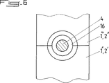
図3、図4および図5に特に示した本発明の第一の実施形態によれば、前記気密エンクロージャ15が、結合手段13を支持する制御軸4の出側部分用または伝達機構14の引っ込み操作軸14”用の通路15’の位置で、軸方向の補助キャップ16により補完され、前記キャップが、前記通路15’の位置で焼きばめ、圧力ばめ、または溶接される(このキャップは、場合によっては制御軸4の通路の気密化手段を支持し、あるいは操作軸14”および/または伝達機構14を回転可能にしながら、それ自体が前記気密性を確保する)。
【0047】
特に図9に示した別の実施形態によれば、マニホルド1の二つの部分1”および1”’の組立によって形成される気密エンクロージャ15が、結合手段13を支持する制御軸4の出側部分用または伝達機構14の引っ込み操作軸14”用の通路15’の位置で閉じられ、この閉鎖が、伝達機構14の少なくとも一つの構成要素および/または軸方向に気密である少なくとも一つの軸受6、12を収容する第三の中空部分17を、開口部または前記通路15’の外面の位置で振動溶接により結合することにより実施され、この第三の中空部分17は、部品1の形成後、結合される。
【0048】
好適には、図5A、図5Bおよび図5Cが示すように、制御軸4/バルブ3のアセンブリが、気密エンクロージャ15内に全体として延びており、制御軸4が、溶接による組立ゾーンまたは組立ラインを通らず、制御軸4の対向端にある2個のバルブ3が、突出して取り付けられ、通路15’の付近に配置されるバルブ3が、操作軸14”の端をはめ込んで受容するための、たとえば長方形の断面の軸方向の盲管18を備え、この盲管が結合手段13を形成する。
【0049】
図3Aが示すように、変形実施形態では、制御軸4の正方形の断面の延長部分として結合手段13を構成可能であり、この延長部分が、アクチュエータに接続される伝達機構14の一部をなす、係合する形状の受容スリーブを備えた凹型部品に、(たとえば係止、接着、圧力ばめおよび/または焼きばめ等により)接続される。
【0050】
制御軸4の作動機構により、開放位置と閉鎖位置(全部または一部)との間でバルブ3が移動可能であり、端位置は、制御軸に結合されて好適にはアクチュエータ14’の近傍に配置される、一つまたは複数の機械ストッパによって画定される。開放位置と閉鎖位置との間の移動は、オールオアナシング式または比例式に行うことができる。
【0051】
かくして、制御軸4と伝達機構14との結合は、外部で、あるいは好適には、マニホルド1の2個の構成部分1”および1”’の組立時に形成された気密エンクロージャの内部で、実施可能であり、その場合、前記凹型または凸型部品は、対応する通過孔15’を通って延びる。
【0052】
さらに、本発明はまた、熱可塑性材料からなる少なくとも二つの部分1”、1”’から上記の吸気マニホルドまたは分配器1を製造する方法を目的とする。
【0053】
この方法は主に、吸気マニホルド1の第一の部分1”を供給し、この第一の部分の上または内部と、補強部5、5’および/または適切な支持および/またはガイド軸受部分6、12とに、それぞれが通過開口部または対応する吸気管2の部分通路2’に配置された複数のバルブ3を含む制御軸4を設置し、場合によっては吸気管2の係合部分2”を含む吸気マニホルド1の少なくとも一つの第二の部分1”’を供給し、バルブ3により制御軸4を封入もしくはサンドイッチ状に挟むことによって、第一の部分1”との組立位置に一つまたは複数の第二の部分1”’を配置し、最後に、吸気マニホルド1の前記少なくとも2個の部分1”、1”’を振動溶接により組み立てることからなる。
【0054】
第二の部分1”’は、前記アセンブリと直接接触することにより制御軸4/バルブ3のアセンブリの封入に直接関与し(場合によっては、管路部分2の2個の部分2’および2”の間の組立ラインの位置で、2個の部分1”および1”’の間に制御軸4をサンドイッチ状に挟んで係止する)、あるいは、カバーの一部すなわち第一の部分1”に対するカバーだけを構成可能であり、第一の部分1”は、場合によっては、制御軸4/バルブ3のアセンブリの支持および回転ガイドだけを行う。
【0055】
従って、有利には、図3および図5が示すように、制御軸4/バルブ3のアセンブリの組立が、前記第一の部分1”へのはめ込みまたは係止により行われ、2個の部分1”および1”’の組立により、駆動通路15’を除いて前記アセンブリの周囲に気密エンクロージャ15を構成し、制御軸4と伝達機構14との結合時に駆動通路が気密にされる。
【0056】
以上により、本発明の基本は、第一に、部分1”、2’上または2個の部分1”、1”’および2’および2”の間に制御軸4/バルブ3のアセンブリを組み立て(前記アセンブリは、場合によっては、軸受部分5、5’、6または11により所定の位置に保持される)、第二に、管路部分2、マニホルドまたは分配器1、または本発明による調節装置を含むように構成された他のあらゆる物体または構造の、2個の構成部分1”および1”’、2’および2”の組立操作を行うことからなる。
【0057】
本発明により、調節装置の設置および組立に必要な操作が最小限で済み(既存の製造方法に干渉せず、また、この製造方法を延長しない)、小型で、しかも高信頼性の気密性を保証しながら、前記調節装置を完全に統合できる(衝突からの保護)技術的な解決策に到達することができる。
【0058】
もちろん、本発明は、添付図面に関して記載された実施形態に制限されるものではない。本発明の範囲を逸脱せずに、特に各種要素の構成の観点から、あるいは同等の代替技術によって、様々な変形を検討することができる。
【図面の簡単な説明】
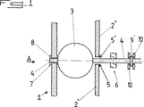
【図1】 本発明による調節装置を含む管路部分の側面立面図と断面図である。
【図2】 図1の管路部分を方向Aからみた図である。
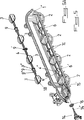
【図3】 本発明の第一の変形実施形態に従って、吸気管の構成部分を支持するマニホルドまたは分配器の壁部分の位置に、バルブを備えた制御軸を組み立てる前(図3A)と、組み立てた後(図3B)とで、吸気マニホルドの一部を示す部分断面斜視図である。
【図4】 図3Bに示された吸気マニホルドの一部の拡大詳細図である。
【図5】 本発明の第二の変形実施形態に従って、吸気管が通じる開口部の位置に、バルブを備えた制御軸を組み立てる前(図5A)と、このような軸を組み立てた後(図5B)と、伝達機構およびアクチュエータを組み立てた後(図5C)とで、吸気マニホルドの一部を示す部分断面斜視図である。
【図6】 図5に示したキャップの方向Bからみた詳細図である(伝達機構14は省略されている)。
【図7】 気密エンクロージャで囲まれた吸気管の詳細な側面立面図である。
【図8】 マニホルドの二つの部分の振動溶接による通路位置への組立(図8A、8Bおよび8C:正面斜視図)と、前記通路の外面位置への第三の部分の組立による気密化(図8D:側面立面図)とを示す、部分概略図である。
【図9】 本発明の別の実施形態に従って、図5に示したマニホルドの通路15’に取り付けられた、図8Dの解決方法を示す側面立面断面図である。[0001]
The present invention relates to the field of controlling the flow of fluids, in particular airflows, in particular in the range of intake air for heat engines, for example in connection with an intake manifold, and generally the flow control in the passage is arranged in this passage, The present invention relates to a device controlled by components operable by a control shaft.
[0002]
More particularly, the present invention is directed to a device for regulating the flow in a conduit section or passage, an intake manifold including the device, and a method for manufacturing such a manifold.
[0003]
Currently, when incorporating a flow or flow adjustment or control device into a passageway or equivalent in a pipeline section, generally the adjustment is made after the opening has been cut out in the pipeline section during one or more individual operations. This is done by assembling a lateral insert supporting the device into the conduit part or by installing an intermediate conduit section with the adjusting device between two parts separated from the conduit part. .
[0004]
However, these known methods require the implementation of complex inserts that include pre-assembled wall portions or bearing structures as well as adjustment components, and with wall portions that contain conduit portions or the like. Intermediate or plug-in installations that are very difficult to assemble tightly and tightly or that are used only when assembling the adjustment part and do not actually constitute a structural part of the conduit section or equivalent Or it is necessary to supply and install additional integrated parts.
[0005]
Moreover, the above known methods generally form a weak zone at the assembly surface or assembly line position of the various components (fitting parts), making it possible to manufacture the pipeline part (without adjusting device) or the equivalent itself. On the other hand, many technical operations or a plurality of additional parts are required.
[0006]
Further, the assembly obtained as a result of these known methods generally has a larger outer dimension due to the configuration, since the control part generally protrudes eccentrically.
[0007]
The present invention is particularly aimed at overcoming at least some of these disadvantages.
[0008]
To this end, the present invention is directed to a device for regulating the flow of fluid, in particular airflow, in at least one duct section, passage or the like, by means of a valve or similar rotary closure part supported by a control shaft. Encloses each assembly of the valve / control shaft rotatably between two engaging portions formed by assembling the pipe part or the parts by friction welding or vibration welding, and the wall of the pipe part And / or the structure of the part including the at least one conduit portion in the structure of the involved conduit portion by attaching to the corresponding containment reinforcement provided on one or more corresponding separation or eccentric bearings It is characterized by being incorporated at the position of the inside opening.
[0009]
The invention will be better understood from the following description of preferred embodiments, given by way of example and not limitation with reference to the accompanying schematic drawings.
[0010]
The attached figure shows that a
[0011]
According to the present invention, each assembly of the
[0012]
The present invention also applies to a plurality of
[0013]
Thus, according to a preferred embodiment of the invention, the adjusting device comprises a
[0014]
The expression “pipe section” here means any circular or non-circular passage that can be closed by a valve-type moving part. This passage may in some cases be limited to a simple transverse opening or passage opening, in which case the axial or longitudinal dimension of the
[0015]
The
[0016]
According to an embodiment, the
[0017]
Furthermore, an assembly line or
[0018]
The assembly interface is such that these surfaces lead to at least one
[0019]
According to another embodiment of the present invention, the
[0020]
The support function and guide function of the
[0021]
Thus, in particular according to the first variant embodiment of the invention shown in FIGS. 1, 2, 3 and 4, the
[0022]
Advantageously, the
[0023]
The
[0024]
This embodiment of the present invention is particularly applicable when the
[0025]
According to a second variant embodiment shown in FIGS. 1 to 2, at least one
[0026]
In the above two variant embodiments, in order to facilitate the rotation guide of the
[0027]
The
[0028]
According to a third variant embodiment of the invention shown in FIGS. 3 and 4, the
[0029]
For example, the rotary guide bearing 11 pre-assembled as a ball bearing or a needle roller bearing is sometimes sealed as a whole in the support bearing 12 and can be protected and translated, so that the
[0030]
Of course, it is obvious to those skilled in the art that the support function and the guide function of the
[0031]
The
[0032]
The assembly of the
[0033]
The
[0034]
However, according to a preferred embodiment of the invention, the two
[0035]
The tightness in the passage position of the
[0036]
In particular, FIGS. 8 and 9 show an embodiment of the third solution described above.
[0037]
As these figures show, the passage 15 'is first laterally moved during assembly when
[0038]
Next, the matching
[0039]
The present invention also includes at least two
[0040]
Such an intake manifold or
[0041]
Actuator 14 'can be pneumatic, electrical, mechanical or the like.
[0042]
According to a preferred embodiment of the present invention, the
[0043]
The
[0044]
The assembly of the
[0045]
According to the variant embodiment of the invention specifically shown in FIGS. 3 to 5, 7 and 9, the
[0046]
According to a first embodiment of the invention, particularly shown in FIGS. 3, 4 and 5, the
[0047]
In particular, according to another embodiment shown in FIG. 9, the
[0048]
Preferably, as shown in FIGS. 5A, 5B and 5C, the assembly of the
[0049]
As shown in FIG. 3A, in an alternative embodiment, the coupling means 13 can be configured as an extension of the square cross section of the
[0050]
The
[0051]
Thus, the coupling between the
[0052]
Furthermore, the present invention is also directed to a method of manufacturing the intake manifold or
[0053]
This method mainly supplies the
[0054]
The
[0055]
Thus, advantageously, as shown in FIGS. 3 and 5, the assembly of the
[0056]
Thus, the basis of the present invention is that firstly the assembly of the
[0057]
According to the present invention, the operation required for installing and assembling the adjusting device is minimized (does not interfere with the existing manufacturing method and does not extend the manufacturing method), and is small in size and highly reliable. While guaranteeing, a technical solution can be reached in which the adjusting device can be fully integrated (protection against collisions).
[0058]
Of course, the invention is not limited to the embodiments described with reference to the accompanying drawings. Various modifications can be considered without departing from the scope of the present invention, particularly in terms of the configuration of various elements or by equivalent alternative techniques.
[Brief description of the drawings]
1 is a side elevational view and a cross-sectional view of a conduit section including an adjusting device according to the present invention.
FIG. 2 is a view of the pipeline portion of FIG.
FIG. 3 shows, before assembling a control shaft with a valve (FIG. 3A) at the position of the manifold or distributor wall part supporting the intake pipe components according to the first variant embodiment of the invention (FIG. 3A); FIG. 3B is a partial cross-sectional perspective view showing a portion of the intake manifold after (FIG. 3B).
4 is an enlarged detail view of a portion of the intake manifold shown in FIG. 3B. FIG.
FIG. 5 shows that before assembling a control shaft with a valve at the position of the opening through which the intake pipe communicates (FIG. 5A) and after assembling such a shaft according to a second variant embodiment of the invention (FIG. 5). 5B) and a partial cross-sectional perspective view showing a portion of the intake manifold after the transmission mechanism and actuator are assembled (FIG. 5C).
6 is a detailed view seen from the direction B of the cap shown in FIG. 5 (the
FIG. 7 is a detailed side elevation view of an intake pipe surrounded by an airtight enclosure.
FIG. 8 shows assembly of the two parts of the manifold into the passage position by vibration welding (FIGS. 8A, 8B and 8C: front perspective view) and airtightness by assembling the third part to the outer surface position of the passage (FIG. 8). 8D: side elevational view).
9 is a side elevation cross-sectional view of the solution of FIG. 8D attached to the
Claims (10)
シリンダヘッドに前記チャンバを接続する管路部分の形状に形成された複数の吸気管(2)と、
制御軸(4)および前記制御軸(4)に支持されたバルブ(3)を有し、前記マニホルド(1)の構造と一体に形成され、ベアリング(6)に回動可能に取付けられる流れ調節装置と、
一方を他方に接合する少なくとも2つの係合部分(1”,1”’)を有する前記マニホルド(1)と
を備えている吸気マニホルドにおいて、
前記2つの部分(1”,1”’)が少なくとも前記チャンバの係合部分を形成し、前記ベアリング(6)が前記吸気管(2)の外側にある部分の組立範囲内に位置する前記部分(1”,1”’)に形成され、
前記制御軸(4)が前記制御軸(4)の並進ブロッキングストッパ(10)と協働する少なくとも一つの円筒形の突起(9’)を備え、
前記調節装置が前記マニホルド(1)の前記チャンバの壁(1’)と一体に形成される前記吸気管(2)の接合範囲に位置する前記吸気管(2)の一端近傍で軸方向に延在しており、
前記ベアリング(6)および前記制御軸(4)の前記並進ブロッキングストッパ(10)が前記マニホルド(1)のチャンバの壁(1’)に形成され、
前記マニホルドを構成する前記部分(1”、1”’)の組立体が前記マニホルド(1)の壁(1’)と一体になって前記吸気管(2)の組立体の接合範囲を囲むように気密エンクロージャ(15)を形成し、
前記気密エンクロージャ(15)が、環状軸プラグ(16)をアクチュエータ(14’)に取付けられた回転結合手段(14)用の通路(15’)に焼嵌め、圧力嵌め、または溶接することによって、前記回転結合手段(14)と離して、かつ前記回転結合手段(14)を支持する前記制御軸(4)の部分を有するように前記通路(15’)の位置に補完されていることを特徴とする吸気マニホルド。A chamber of the manifold (1) ;
A plurality of intake pipes (2) formed in the shape of a conduit portion connecting the chamber to the cylinder head;
Flow control having a control shaft (4) and a valve (3) supported by the control shaft (4) , integrally formed with the structure of the manifold (1), and rotatably attached to the bearing (6) Equipment,
An intake manifold comprising said manifold (1) having at least two engaging portions (1 ", 1"') joining one to the other,
It said two parts (1 ", 1"') forms an engagement portion of at least the chamber, the said bearing (6) is positioned within the assembly range of the outer near Ru portion of the intake pipe (2) Formed in the part (1 ", 1"')
The control shaft (4) comprises at least one cylindrical protrusion (9 ') cooperating with a translational blocking stopper (10) of the control shaft (4);
The adjusting device extends in the axial direction in the vicinity of one end of the intake pipe (2) located in a joint range of the intake pipe (2) formed integrally with the chamber wall (1 ′) of the manifold (1). Exist,
The translation blocking stopper (10) of the bearing (6) and the control shaft (4) is formed in the chamber wall (1 ′) of the manifold (1);
The assembly of the parts (1 ″, 1 ″ ′) constituting the manifold is integrated with the wall (1 ′) of the manifold (1) so as to surround the joint range of the assembly of the intake pipe (2). Forming an airtight enclosure (15) in the
The hermetic enclosure (15) is shrink-fitted, pressure-fitted, or welded by an annular shaft plug (16) into a passage (15 ') for rotational coupling means (14) attached to an actuator (14') , wherein a distance between the rotational coupling means (14), and is complemented to the position of said passage so as to have a portion of said control shaft for supporting the rotary coupling means (14) (4) (15 ') Intake manifold.
シリンダヘッドに前記チャンバを接続する管路部分の形状に形成された複数の吸気管(2)と、
制御軸(4)および前記制御軸(4)に支持されたバルブ(3)を有し、前記マニホルド(1)の構造と一体に形成され、ベアリング(6)に回動可能に取付けられる流れ調節装置と、
一方を他方に接合する少なくとも2つの係合部分(1”,1”’)を有する前記マニホルド(1)と
を備えている吸気マニホルドにおいて、
前記2つの部分(1”,1”’)が少なくとも前記チャンバの係合部分を形成し、前記ベアリング(6)が前記吸気管(2)の外側にある部分の組立範囲内に位置する前記部分(1”,1”’)に形成され、
前記制御軸(4)が前記制御軸(4)の並進ブロッキングストッパ(10)と協働する少なくとも一つの円筒形の突起(9’)を備え、
前記調節装置が前記マニホルド(1)の前記チャンバの壁(1’)と一体に形成される前記吸気管(2)の接合範囲に位置する前記吸気管(2)の一端近傍で軸方向に延在しており、
前記ベアリング(6)および前記制御軸(4)の前記並進ブロッキングストッパ(10)が前記マニホルド(1)のチャンバの壁(1’)に形成され、
前記マニホルドを構成する前記部分(1”、1”’)の組立体が前記マニホルド(1)の壁(1’)と一体になって前記吸気管(2)の組立体の接合範囲を囲むように気密エンクロージャ(15)を形成し、
前記マニホルド(1)の前記2つの部分(1”、1”’)を組み立てることにより形成された前記気密エンクロージャ(15)が、前記2つの部分(1”、1”’)の外表面での相互接続と、振動溶接と、アクチュエータ(14’)に取付けられた回転結合手段(14)および軸方向の前記ベアリング(6)を密封する第3の中空部分(17)とにより、前記制御軸(4)に支持される前記回転結合手段(14)用の通路(15’)の位置で気密にされていることを特徴とする吸気マニホルド。A chamber of the manifold (1) ;
A plurality of intake pipes (2) formed in the shape of a conduit portion connecting the chamber to the cylinder head;
Flow control having a control shaft (4) and a valve (3) supported by the control shaft (4) , integrally formed with the structure of the manifold (1), and rotatably attached to the bearing (6) Equipment,
An intake manifold comprising said manifold (1) having at least two engaging portions (1 ", 1"') joining one to the other,
The two parts (1 ″, 1 ″ ′) form at least an engaging part of the chamber and the bearing (6) is located within the assembly range of the part outside the intake pipe (2) (1 ", 1"')
The control shaft (4) comprises at least one cylindrical protrusion (9 ') cooperating with a translational blocking stopper (10) of the control shaft (4);
The adjusting device extends in the axial direction in the vicinity of one end of the intake pipe (2) located in a joint range of the intake pipe (2) formed integrally with the chamber wall (1 ′) of the manifold (1). Exist,
The translation blocking stopper (10) of the bearing (6) and the control shaft (4) is formed in the chamber wall (1 ′) of the manifold (1);
The assembly of the parts (1 ″, 1 ″ ′) constituting the manifold is integrated with the wall (1 ′) of the manifold (1) so as to surround the joint range of the assembly of the intake pipe (2). Forming an airtight enclosure (15) in the
The hermetic enclosure (15) formed by assembling the two parts (1 ″, 1 ″ ′) of the manifold (1) is at the outer surface of the two parts (1 ″, 1 ″ ′). By means of the interconnection, vibration welding, the rotary coupling means (14) attached to the actuator (14 ′) and the third hollow part (17) sealing the axial bearing (6) , the control shaft ( 4. An intake manifold characterized in that it is airtight at the position of the passage (15 ′) for the rotary coupling means (14) supported by 4).
前記制御軸(4)が前記組立範囲または組立ラインと交差しておらず、
前記制御軸(4)の対向する端部の前記バルブ(3)が突出して固定されており、
前記バルブ(3)が前記回転結合手段(14)を構成する操作軸(14”)の端部の挿入部により軸方向の盲管(18)のハウジングに取付けられた前記通路(15’)近傍に位置していることを特徴とする請求項1または2に記載の吸気マニホルド。The adjusting device extends entirely within the hermetic enclosure (15);
The control axis (4) does not intersect the assembly range or assembly line;
The valve of the opposite ends of the control shaft (4) (3) is fixed to protrude,
Said passage (15 ') near which it is attached to the housing of the valve (3) is blind tube in the axial direction by the insertion of the end of the operating shaft constituting the rotary coupling means (14) (14') (18) The intake manifold according to claim 1, wherein the intake manifold is located in the intake manifold.
前記制御軸(4)が前記2つの部分(1”,1”’)の他方(1”’)に接触することなく前記部分(1”,1”’)の間に封入されており、
前記他方の部分(1”’)は前記2つの部分(1”,1”’)の組立後に前記制御軸(4)が前記ベアリング(6)から外れるのを防止することとなることを特徴とする請求項1〜5のいずれか一項に記載の吸気マニホルド。The bearing (6) is formed on one of the parts (1 ″, 1 ″ ′);
The control shaft (4) is enclosed between the parts (1 ", 1"') without contacting the other (1 "') of the two parts (1", 1 "');
The other part (1 ″ ′) prevents the control shaft (4 ) from being detached from the bearing (6) after the assembly of the two parts (1 ″, 1 ″ ′). The intake manifold according to any one of claims 1 to 5.
Applications Claiming Priority (3)
| Application Number | Priority Date | Filing Date | Title |
|---|---|---|---|
| FR9910999A FR2797931B1 (en) | 1999-08-31 | 1999-08-31 | DEVICE FOR CONTROLLING THE FLOW IN A DUCT PORTION OR A PASSAGE AND MANIFOLD COMPRISING SUCH A DEVICE |
| FR99/10999 | 1999-08-31 | ||
| PCT/FR2000/002413 WO2001016473A1 (en) | 1999-08-31 | 2000-08-31 | Device for regulating flow in a duct portion or an intake passage and manifold comprising same |
Publications (3)
| Publication Number | Publication Date |
|---|---|
| JP2003508668A JP2003508668A (en) | 2003-03-04 |
| JP2003508668A5 JP2003508668A5 (en) | 2007-10-18 |
| JP4549596B2 true JP4549596B2 (en) | 2010-09-22 |
Family
ID=9549482
Family Applications (1)
| Application Number | Title | Priority Date | Filing Date |
|---|---|---|---|
| JP2001519999A Expired - Fee Related JP4549596B2 (en) | 1999-08-31 | 2000-08-31 | Device for regulating flow in a part or passage of a conduit and an intake manifold including the device |
Country Status (7)
| Country | Link |
|---|---|
| US (1) | US6895926B1 (en) |
| EP (1) | EP1212525B1 (en) |
| JP (1) | JP4549596B2 (en) |
| AT (1) | ATE334305T1 (en) |
| DE (1) | DE60029598T2 (en) |
| FR (1) | FR2797931B1 (en) |
| WO (1) | WO2001016473A1 (en) |
Families Citing this family (30)
| Publication number | Priority date | Publication date | Assignee | Title |
|---|---|---|---|---|
| DE10131109A1 (en) * | 2001-06-27 | 2003-01-09 | Mann & Hummel Filter | Process for producing a switch flap assembly |
| FR2833061B1 (en) | 2001-12-05 | 2006-10-06 | Mark Iv Systemes Moteurs Sa | DEVICE FOR CONTROLLING THE FLOW IN A CONDUIT PORTION OR THE LIKE |
| JP4463488B2 (en) * | 2003-03-27 | 2010-05-19 | 本田技研工業株式会社 | Throttle body |
| FR2864167B1 (en) * | 2003-12-19 | 2006-02-24 | Mark Iv Systemes Moteurs Sa | TWO-PART INTAKE MANIFOLD AND METHOD FOR MANUFACTURING THE SAME |
| JP2005248987A (en) * | 2004-03-01 | 2005-09-15 | Denso Corp | Bearing support device |
| DE102004021125A1 (en) * | 2004-04-29 | 2005-12-01 | Mann + Hummel Gmbh | Flap arrangement in the flange region of an intake system of an internal combustion engine |
| JP2006002601A (en) * | 2004-06-16 | 2006-01-05 | Mitsubishi Electric Corp | Intake manifold and its manufacturing method |
| JP4626409B2 (en) * | 2005-06-03 | 2011-02-09 | 日産自動車株式会社 | Engine intake manifold |
| US7438087B1 (en) | 2005-09-30 | 2008-10-21 | Taylor Innovations, L.L.C. | Overpressure rotary valve assembly with locking pin and collapsible member |
| FR2891886B1 (en) * | 2005-10-07 | 2010-04-02 | Mark Iv Systemes Moteurs Sa | CLAMP CONTROL DEVICE AND ADMISSION MANIFOLD COMPRISING AT LEAST ONE SUCH DEVICE |
| JP2007138840A (en) * | 2005-11-18 | 2007-06-07 | Denso Corp | Intake device and method for manufacturing the same |
| JP4636328B2 (en) * | 2006-01-20 | 2011-02-23 | アイシン精機株式会社 | Intake control device |
| TWI441835B (en) * | 2006-07-12 | 2014-06-21 | Novartis Ag | Novel polymers |
| JP2008038759A (en) * | 2006-08-07 | 2008-02-21 | Toyota Motor Corp | Variable intake device of internal combustion engine |
| DE102006039827A1 (en) * | 2006-08-25 | 2008-02-28 | Mahle International Gmbh | Switching device for controlling a gas flow |
| US7370671B2 (en) * | 2006-10-06 | 2008-05-13 | Taylor Innovations, L.L.C. | Valve activation assembly which mechanically collapses a collapsible member in response to both overpressure and underpressure conditions |
| DE102007005686B4 (en) * | 2007-02-05 | 2009-01-02 | Siemens Ag | Intake manifold for an internal combustion engine |
| KR100831582B1 (en) * | 2007-03-14 | 2008-05-22 | 주식회사 케피코 | Tumble control valve assembly |
| KR100789646B1 (en) | 2007-03-14 | 2007-12-27 | 주식회사 케피코 | Tumble control valve assembly |
| FR2927124B1 (en) * | 2008-02-05 | 2013-02-22 | Mark Iv Systemes Moteurs Sa | PROCESS FOR PRODUCING A SUPPORT PLATE FOR CHAMPS OF FLAP AND SUPPORT PLATE |
| KR101114085B1 (en) * | 2008-07-14 | 2012-02-21 | 기아자동차주식회사 | Valve shaft supporting structure in variable intake manifold |
| US8316812B2 (en) * | 2008-09-09 | 2012-11-27 | Mark Iv Systemes Moteurs Usa, Inc. | Dual output flow control actuator |
| JP5243288B2 (en) * | 2009-02-02 | 2013-07-24 | 愛三工業株式会社 | Bearing device |
| JP2011220143A (en) * | 2010-04-06 | 2011-11-04 | Denso Corp | Air-intake apparatus of internal combustion engine |
| DE102011087234A1 (en) * | 2011-11-28 | 2013-05-29 | Mahle International Gmbh | Frischluftzuführeinrichtung |
| FR2983250B1 (en) * | 2011-11-28 | 2013-12-20 | Valeo Sys Controle Moteur Sas | GAS INTAKE SYSTEM FOR A VEHICLE ENGINE |
| KR101531331B1 (en) * | 2013-12-30 | 2015-06-25 | 말레동현필터시스템 주식회사 | Variable induction valve module and its manufacturing method |
| DE102015204604A1 (en) * | 2015-03-13 | 2016-09-15 | Mahle International Gmbh | Suction module of a fresh air system |
| JP6396267B2 (en) * | 2015-08-25 | 2018-09-26 | 株式会社マーレ フィルターシステムズ | Intake device for internal combustion engine |
| USD858579S1 (en) * | 2018-03-29 | 2019-09-03 | Wen Chen | Air flap |
Family Cites Families (12)
| Publication number | Priority date | Publication date | Assignee | Title |
|---|---|---|---|---|
| JPS6288875U (en) * | 1985-11-22 | 1987-06-06 | ||
| FR2606115B1 (en) * | 1986-10-31 | 1989-03-10 | Peugeot | BUTTERFLY VALVE IN PARTICULAR FOR A MOTOR VEHICLE AND ITS APPLICATION TO A CARBURETOR |
| DE3833846A1 (en) * | 1987-10-16 | 1989-04-27 | Volkswagen Ag | Intake arrangement for an internal combustion engine with a flap generating a swirl and/or turbulence |
| JP2501786Y2 (en) * | 1990-10-03 | 1996-06-19 | ブラザー工業株式会社 | Bearing support structure |
| WO1995016112A1 (en) * | 1993-12-10 | 1995-06-15 | Mitsubishi Jidosha Kogyo Kabushiki Kaisha | Suction control device for a multi-cylinder internal combustion engine |
| US5875758A (en) * | 1995-04-06 | 1999-03-02 | E. I. Du Pont De Nemours And Company | Resin air intake system provided with intake control valve |
| JPH08277717A (en) * | 1995-04-06 | 1996-10-22 | Du Pont Kk | Resin intake system provided with intake control valve |
| DE19523870A1 (en) * | 1995-06-30 | 1997-01-02 | Mann & Hummel Filter | Suction device made of thermoplastic |
| DE19726162C1 (en) * | 1997-06-20 | 1999-01-28 | Bosch Gmbh Robert | Intake air distributor |
| US6098586A (en) * | 1997-08-27 | 2000-08-08 | Siemens Canada Limited | Integrated intake manifold and air cleaner system |
| US5979871A (en) * | 1998-03-30 | 1999-11-09 | Ford Motor Company | Clamshell throttle valve assembly |
| US6135418A (en) * | 1999-02-10 | 2000-10-24 | Eaton Corporation | Low-leakage air valve for variable air intake system |
-
1999
- 1999-08-31 FR FR9910999A patent/FR2797931B1/en not_active Expired - Lifetime
-
2000
- 2000-08-31 DE DE60029598T patent/DE60029598T2/en not_active Expired - Lifetime
- 2000-08-31 JP JP2001519999A patent/JP4549596B2/en not_active Expired - Fee Related
- 2000-08-31 AT AT00960770T patent/ATE334305T1/en not_active IP Right Cessation
- 2000-08-31 WO PCT/FR2000/002413 patent/WO2001016473A1/en active IP Right Grant
- 2000-08-31 US US10/069,507 patent/US6895926B1/en not_active Expired - Lifetime
- 2000-08-31 EP EP00960770A patent/EP1212525B1/en not_active Expired - Lifetime
Also Published As
| Publication number | Publication date |
|---|---|
| JP2003508668A (en) | 2003-03-04 |
| US6895926B1 (en) | 2005-05-24 |
| FR2797931A1 (en) | 2001-03-02 |
| DE60029598D1 (en) | 2006-09-07 |
| ATE334305T1 (en) | 2006-08-15 |
| DE60029598T2 (en) | 2007-07-19 |
| EP1212525A1 (en) | 2002-06-12 |
| EP1212525B1 (en) | 2006-07-26 |
| FR2797931B1 (en) | 2001-10-05 |
| WO2001016473A1 (en) | 2001-03-08 |
Similar Documents
| Publication | Publication Date | Title |
|---|---|---|
| JP4549596B2 (en) | Device for regulating flow in a part or passage of a conduit and an intake manifold including the device | |
| JP4849389B2 (en) | Flap valve device in flange part of internal combustion engine intake device | |
| ES2236892T3 (en) | ELECTROIMAN, ESPECIALLY TO OPERATE VALVES. | |
| JP2003106175A (en) | Throttling device provided with driving device storing part and driving device contact forming part | |
| US6935573B2 (en) | Expansion valve | |
| CN102759233A (en) | Electronic expansion valve | |
| KR20200054898A (en) | Bearing system | |
| JP7175842B2 (en) | ELECTRIC MOTOR, ELECTRIC PUMP, AND CONNECTOR MANUFACTURING METHOD | |
| JPH02227555A (en) | Pressure regulation unit | |
| JP3819716B2 (en) | Gas flow control device | |
| JP2002174391A (en) | Valve interposed in resin pipe line without interruption of fluid | |
| JPH1030744A (en) | Electric flow control valve | |
| JP2536825Y2 (en) | Butterfly valve | |
| JP2005036805A (en) | Transmission control of pressure pulse in intake manifold of engine | |
| JP4593538B2 (en) | Valve device, butterfly valve assembly method, and throttle body manufacturing method | |
| CN112005036A (en) | Flow path switching valve and method for manufacturing same | |
| JP7288531B2 (en) | Motor-operated valve stator and motor-operated valve | |
| JP7302910B2 (en) | valve device | |
| US11772211B2 (en) | Flow control valve | |
| JP7070297B2 (en) | Fuel tank switchgear | |
| JPH09196194A (en) | Electric flow control valve | |
| JP3041183B2 (en) | Gas shut-off valve | |
| JP2529806Y2 (en) | speed controller | |
| WO2021006139A1 (en) | Electric actuator and attachment structure for same, and valve body drive device | |
| JP6782128B2 (en) | Ball valve |
Legal Events
| Date | Code | Title | Description |
|---|---|---|---|
| A521 | Request for written amendment filed |
Free format text: JAPANESE INTERMEDIATE CODE: A523 Effective date: 20070827 |
|
| A621 | Written request for application examination |
Free format text: JAPANESE INTERMEDIATE CODE: A621 Effective date: 20070827 |
|
| A131 | Notification of reasons for refusal |
Free format text: JAPANESE INTERMEDIATE CODE: A131 Effective date: 20090728 |
|
| A601 | Written request for extension of time |
Free format text: JAPANESE INTERMEDIATE CODE: A601 Effective date: 20091021 |
|
| A602 | Written permission of extension of time |
Free format text: JAPANESE INTERMEDIATE CODE: A602 Effective date: 20091028 |
|
| A521 | Request for written amendment filed |
Free format text: JAPANESE INTERMEDIATE CODE: A523 Effective date: 20100126 |
|
| A131 | Notification of reasons for refusal |
Free format text: JAPANESE INTERMEDIATE CODE: A131 Effective date: 20100219 |
|
| A521 | Request for written amendment filed |
Free format text: JAPANESE INTERMEDIATE CODE: A523 Effective date: 20100518 |
|
| TRDD | Decision of grant or rejection written | ||
| A01 | Written decision to grant a patent or to grant a registration (utility model) |
Free format text: JAPANESE INTERMEDIATE CODE: A01 Effective date: 20100608 |
|
| A01 | Written decision to grant a patent or to grant a registration (utility model) |
Free format text: JAPANESE INTERMEDIATE CODE: A01 |
|
| A61 | First payment of annual fees (during grant procedure) |
Free format text: JAPANESE INTERMEDIATE CODE: A61 Effective date: 20100707 |
|
| R150 | Certificate of patent or registration of utility model |
Free format text: JAPANESE INTERMEDIATE CODE: R150 |
|
| FPAY | Renewal fee payment (event date is renewal date of database) |
Free format text: PAYMENT UNTIL: 20130716 Year of fee payment: 3 |
|
| R250 | Receipt of annual fees |
Free format text: JAPANESE INTERMEDIATE CODE: R250 |
|
| LAPS | Cancellation because of no payment of annual fees |