JP4549552B2 - Method and apparatus for fast computation of natural logarithm log (X) - Google Patents
Method and apparatus for fast computation of natural logarithm log (X) Download PDFInfo
- Publication number
- JP4549552B2 JP4549552B2 JP2001039370A JP2001039370A JP4549552B2 JP 4549552 B2 JP4549552 B2 JP 4549552B2 JP 2001039370 A JP2001039370 A JP 2001039370A JP 2001039370 A JP2001039370 A JP 2001039370A JP 4549552 B2 JP4549552 B2 JP 4549552B2
- Authority
- JP
- Japan
- Prior art keywords
- log
- binary
- mantissa
- value
- calculating
- Prior art date
- Legal status (The legal status is an assumption and is not a legal conclusion. Google has not performed a legal analysis and makes no representation as to the accuracy of the status listed.)
- Expired - Fee Related
Links
Images


Classifications
-
- G—PHYSICS
- G06—COMPUTING OR CALCULATING; COUNTING
- G06F—ELECTRIC DIGITAL DATA PROCESSING
- G06F1/00—Details not covered by groups G06F3/00 - G06F13/00 and G06F21/00
- G06F1/02—Digital function generators
- G06F1/03—Digital function generators working, at least partly, by table look-up
- G06F1/035—Reduction of table size
- G06F1/0356—Reduction of table size by using two or more smaller tables, e.g. addressed by parts of the argument
-
- G—PHYSICS
- G06—COMPUTING OR CALCULATING; COUNTING
- G06F—ELECTRIC DIGITAL DATA PROCESSING
- G06F2101/00—Indexing scheme relating to the type of digital function generated
- G06F2101/10—Logarithmic or exponential functions
-
- G—PHYSICS
- G06—COMPUTING OR CALCULATING; COUNTING
- G06F—ELECTRIC DIGITAL DATA PROCESSING
- G06F7/00—Methods or arrangements for processing data by operating upon the order or content of the data handled
- G06F7/38—Methods or arrangements for performing computations using exclusively denominational number representation, e.g. using binary, ternary, decimal representation
- G06F7/48—Methods or arrangements for performing computations using exclusively denominational number representation, e.g. using binary, ternary, decimal representation using non-contact-making devices, e.g. tube, solid state device; using unspecified devices
- G06F7/483—Computations with numbers represented by a non-linear combination of denominational numbers, e.g. rational numbers, logarithmic number system or floating-point numbers
Landscapes
- Engineering & Computer Science (AREA)
- Theoretical Computer Science (AREA)
- Physics & Mathematics (AREA)
- General Engineering & Computer Science (AREA)
- General Physics & Mathematics (AREA)
- Apparatus For Radiation Diagnosis (AREA)
- Image Processing (AREA)
- Image Analysis (AREA)
Description
【0001】
【発明の属する技術分野】
本発明は、演算集約的なアルゴリズムを計算するための方法及び装置に関し、より具体的には、コンピュータ断層撮影画像処理やその他の用途に特に有用な方式でlog(x)、又は同様な−log(x)を計算するための方法及び装置に関する。
【0002】
【発明の背景】
周知のコンピュータ断層撮影(CT)イメージング・システムの少なくとも1つの構成では、X線源は、デカルト座標系のX−Y平面(一般に「画像作成面」と呼ばれる)内に位置するようにコリメートされたファンビーム(扇形状ビーム)を放出する。X線ビームは、例えば患者などの画像作成対象物を透過する。ビームは、この対象物によって減衰を受けた後、放射線検出器のアレイ上に入射する。検出器アレイで受け取った減衰したビーム状放射線の強度は、対象物によるX線ビームの減衰に依存する。このアレイの各検出器素子は、それぞれの検出器位置でのビーム減衰の計測値に相当する電気信号を別々に発生させる。すべての検出器からの減衰量計測値を別々に収集し、透過プロフィールが作成される。
【0003】
周知の第3世代CTシステムでは、X線源及び検出器アレイは、X線ビームが画像作成対象物を切る角度が一定に変化するようにして、画像作成面内でこの画像作成対象物の周りをガントリと共に回転する。あるガントリ角度で検出器アレイより得られる一群のX線減衰量計測値(すなわち、投影データ)のことを「ビュー(view)」という。また、画像作成対象物の「スキャン・データ」は、X線源と検出器が1回転する間に、様々なガントリ角度、すなわちビュー角度で得られるビューの集合からなる。アキシャル・スキャンでは、この投影データを処理し、画像作成対象物を透過させて得た2次元スライスに対応する画像を構成させる。投影データの組から画像を再構成させるための一方法に、当技術分野においてフィルタ補正逆投影法(filtered back projection)と呼ぶものがある。この処理方法では、スキャンにより得た減衰量計測値を「CT値」、別名「ハウンスフィールド値」という整数に変換し、これらの整数値を用いて陰極線管ディスプレイ上の対応するピクセルの輝度を制御する。
【0004】
コンピュータ断層撮影(CT)画像処理において、負の自然対数関数−log(x)は重要であり且つ演算集約的なアルゴリズムである。周知のシステムでは、この関数は5次多項式を用いて近似されている。しかし、この多項式により消費される処理時間は全体の画像処理時間の20%を超えており、なおかつ比較的大きな近似誤差及び誤差標準偏差を生じさせている。
【0005】
正の浮動小数点数xは次式のように表現できる。
【0006】
x=m×2e 式(1)
上式において、m(1≦m<2)は仮数であり、eは2進の指数である。
【0007】
式(1)を用いると、−log(x)は次式
y=−log(x)=−log(m)−e×log(2) 式(2)
により表記できる。
【0008】
次の式は、領域1≦m<2において有限次数の多項式を用いてlog(m)の近似をしたものである。一般的に言って、多項式の次数が高いほどその近似が良好となるが、演算負荷の大きさは多項式の次数に比例する。例えば、現在使用されている5次多項式では、次式により表記される。
【0009】
【0010】
式(3b)において、a0 〜a6 は事前計算された定数である。−log(x)を計算するためには、6回の加算と6回の乗算が必要であり、さらに仮数及び指数の抽出が必要である。
【0011】
より効率的かつより正確に画像を処理するために、IEEE(Institute of Electrical and Electronic Engineers)の浮動小数点精度に一致した数値確度を達成しながら、−log(x)の計算に使用する近似の複雑性を低下させるための方法及び装置を提供することが望ましい。
【0012】
【発明の概要】
したがって、本発明の実施の一形態では、自然対数関数を計算するための方法であって、1と2の間の仮数領域を均等間隔のN個の小領域に区分するステップと、均等間隔のN個の小領域の各々の中心点ai (ここで、i=0,...,N−1)を事前計算するステップと、各小領域に対して、mをある数に対する2進浮動小数点表現の仮数として、mの1次多項式によりlog(m)が小領域内の任意のmに対して事前に選択した確度範囲内で計算されるように、Nの値を十分大きく選択するステップと、mの1次多項式を利用して、演算デバイスのメモリ内に格納された特定の数xの2進浮動小数点表現に対するlog(x)の値を計算するステップと、を含む方法である。
【0013】
この実施形態及び本明細書に記載したその他の実施形態により、IEEEの浮動小数点精度に一致した数値確度を達成しながら、自然対数を計算するために使用する近似の複雑性を低下できることが理解されよう。
【0014】
【発明の実施の形態】
図1及び図2を参照すると、「第3世代」のCTスキャナに典型的なガントリ12を含むものとして、コンピュータ断層撮影(CT)イメージング・システム10を示している。ガントリ12は、このガントリ12の対向面上に位置する検出器アレイ18に向けてX線ビーム16を放出するX線源14を有する。検出器アレイ18は、投射され被検体22(例えば、患者)を透過したX線を一体となって検知する検出器素子20により形成される。検出器アレイ18は、単一スライス構成で製作される場合とマルチ・スライス構成で製作される場合がある。各検出器素子20は、入射したX線ビームの強度を表す電気信号、すなわち患者22を透過したX線ビームの減衰を表す電気信号を発生させる。X線投影データを収集するためのスキャンの間に、ガントリ12及びガントリ上に装着されたコンポーネントは回転中心24の周りを回転する。
【0015】
ガントリ12の回転及びX線源14の動作は、CTシステム10の制御機構26により制御される。制御機構26は、X線源14に電力及びタイミング信号を供給するX線制御装置28と、ガントリ12の回転速度及び位置を制御するガントリ・モータ制御装置30とを含む。制御機構26内にはデータ収集システム(DAS)32があり、これによって検出器素子20からのアナログ・データをサンプリングし、このデータを後続の処理のためにディジタル信号に変換する。画像再構成装置34は、サンプリングされディジタル化されたX線データをDAS32から受け取り、高速で画像再構成を行う。再構成された画像はコンピュータ36に入力として渡され、コンピュータにより大容量記憶装置38内に格納される。
【0016】
コンピュータ36はまた、キーボードを有するコンソール40を介して、オペレータからのコマンド及びスキャン・パラメータを受け取る。付属の陰極線管ディスプレイ42により、オペレータはコンピュータ36からの再構成画像やその他のデータを観察することができる。コンピュータ36は、オペレータの発したコマンド及びパラメータを用いて、DAS32、X線制御装置28及びガントリ・モータ制御装置30に対して制御信号や制御情報を提供する。さらにコンピュータ36は、モータ式テーブル46を制御してガントリ12内での患者22の位置決めをするためのテーブル・モータ制御装置44を操作する。詳細には、テーブル46により患者22の各部分はガントリ開口48を通過できる。
【0017】
画像再構成装置34では、画像を作成するために負の自然対数関数−log(m)を用いている。本発明の実施の一形態では、上記式(3a)の関数log(m)は、次式のように表記できる。
【0018】
【数1】
すなわち、
【0020】
【数2】
。
【0022】
上式において、aは既知の基準点である。上記関数の誤差(error)は次式により表記できる。
【0023】
【数3】
。
【0025】
(m−a)<1であるため、誤差を最小にするためには2つの方式がある。その1つは近似の次数を上げることであり、もう一方はmからaまでの距離を最小にすることである。仮数mは1と2の間にあるため、本発明の実施の一形態では、1と2の間の領域を均等間隔のN個の小領域に区分する。これらの小領域の各々の中心を事前計算し、これを式(4a)及び式(4b)における基準点として使用する。十分に多くの小領域に区分することによって、低い次数の多項式関数によりCTイメージング目的のための十分な確度が得られる。詳細には、小領域の数を十分に大きく選択することにより、具体的な任意の小領域内における任意のmに対してlog(m)の値を1次多項式により当該小領域内で事前に選択した確度範囲内で計算できる。例えば、コンピュータ36は、そのメモリ内に格納した特定の数xの2進浮動小数点表現に対して、mの1次多項式を用いてlog(x)の値を計算する。
【0026】
事前計算した基準点からなる組を用いた1次多項式に基づくlog(m)の近似は、次式で表される。
【0027】
log(m)≒log(ai)+[(m−ai)/ai ] 式(6)
ここで、i=0,...,N−1
1≦ai<2
上式において、ai は所与の仮数mに最も近い基準点である。
【0028】
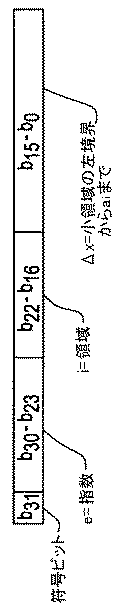
本発明の実施の一形態では、6回の演算処理を要するような式i=round((m−1)×N)を用いて小領域の指標を計算せずに、以下のようにして演算負荷を減少させている。区分アルゴリズムによりメモリ内の2進浮動小数点数の仮数を2つの小領域に分割する。この2つの小領域は、指標iと、仮数mから基準点ai までの距離であるΔxを有する。指標i及びΔxはコンピュータ・システムに格納されたIEEE浮動小数点数から直接抽出され、これにより演算時間が短縮されかつ確度が向上する。実施の一形態では、仮数の区分は図3の例示のように行われる。図において、指標iは0から127までの範囲にあり、各領域は図3に示すデータから抽出される情報を表している。さらに詳細には、単精度IEEE浮動小数点数において、b31は符号ビット、b30は指数eの最上位ビット、b23は指数eの最下位ビット、b22は仮数mの最上位ビット、b0 は仮数mの最下位ビットをそれぞれ表す。(ビットbの番号付けに対して異なる指定を使用することを所望する場合には、当業者によって記述に関して表記上の一貫性のために必要となる適当な変更を行うことができる。)。この単精度の実施形態では、指数eはb30からb23までのビットから直接抽出され、領域iはb22からb16までのビットから直接抽出され、またΔx(仮数mから基準点ai までの距離)はb15からb0 までのビットから直接抽出される。
【0029】
図3に示す抽出を用いて、各小領域における式(6)の最大誤差は次式により推定される。
【0030】
error≦[1/(2ai 2)]×[1/(2N)]2 式(7a)
ここで、i=0,...,N−1
1≦ai<2
。
【0031】
式(7a)から、第1次近似の誤差は常に正であり、誤差に偏りのあることが分かる。最大誤差を最小限にするために、実施の一形態では、式(7a)の平均誤差を式(6)から減算する。したがって、不偏誤差は次式で表される。
【0032】
|error|≦[1/(4Nai)]2 式(7b)
ここで、i=0,...,N−1
1≦ai<2
。
【0033】
式(6)から式(7b)を減算することにより、次式により表される−log(x)の不偏の1次多項式関数が得られる。
【0034】
y=−log(x)≒bi+ciΔx+e×log(2) 式(8)
ここで、i=0,...,N−1
bi=−log(ai)+[1/(4Nai)]2 −[1+(1/(2N))](1/ai)
ci=−1/ai 式(9)
。
【0035】
上式において、ai =1+(i+0.5)/Nであり、またΔxは仮数mから基準点までの距離である。値Δxは、IEEE浮動小数点データから直接抽出される。実施の一形態では、log(2)と、bi 及びci とが事前計算され、初期化時点においてルックアップ・テーブル内に記憶されている。実施の一形態では、bi の値はlog(ai )の事前計算値から決定される。比較してみると、式(8)による演算に必要な時間は、式(3b)による5次近似を計算するのに必要な時間の1/3だけでよい。
【0036】
mとΔxの関係を考慮に入れながら、log(x)、あるいは−log(x))の近似値をmの1次多項式及びlog(ai )の事前計算値を用いて計算する。
【0037】
本発明の実施の一形態では、その画像再構成装置34は、CTイメージング・システム10により収集した投影データから被検体を画像化する際に、ソフトウェアまたはファームウェアにより本発明の1つまたは複数の方法を用いた対数値計算をするように構成されている。
【0038】
本発明の様々な実施形態に関する以上の記述から、IEEE(Institute of Electrical and Electronic Engineers)浮動小数点精度と一致した数値確度を維持しながら、−log(x)を計算するために使用する近似の複雑性を低下させることができることは明らかである。したがって、CTイメージング・システム10により処理される画像では処理がより効率的となると共に、ディテール(細部)が失われることがない。本発明の具体的な実施形態を詳細に記載し図示してきたが、これらは説明および例示のためのものに過ぎず、本発明を限定する意図ではないことを明瞭に理解されたい。例えば、log(x)及び−log(x)に対する改良型の演算の実施形態は、演算の正確性を維持させながら効率を上昇させることを必要とする任意の演算システムに組み込むことができる。さらに、本発明は、本明細書において詳細に検討したものと比べてより高い精度またはより低い精度を有する浮動小数点数と共に使用するのに適している。こうした異なる精度に対応させるために必要となる修正は、本明細書に記載した本発明を完全に理解すれば、当業者には明らかであろう。したがって、本発明の精神及び範囲は特許請求の範囲の各項及びこれと法的に等価なものによって限定されるべきである。
【図面の簡単な説明】
【図1】CTイメージング・システムの外観図である。
【図2】図1に示すシステムのブロック図である。
【図3】本発明の実施の一形態により区分され、IEEEの単精度2進浮動小数点形式で格納されている数を表した図である。
【符号の説明】
10 CTイメージング・システム
12 ガントリ
14 X線源
16 X線ビーム
18 検出器アレイ
20 検出器素子
22 患者
24 回転中心
26 制御機構
32 データ収集システム(DAS)
42 陰極線管ディスプレイ
48 ガントリ開口[0001]
BACKGROUND OF THE INVENTION
The present invention relates to a method and apparatus for computing an operation intensive algorithm, and more particularly, log (x) or similar -log in a manner that is particularly useful for computed tomography image processing and other applications. It relates to a method and an apparatus for calculating (x).
[0002]
BACKGROUND OF THE INVENTION
In at least one configuration of a known computed tomography (CT) imaging system, the x-ray source is collimated to lie in the XY plane (commonly referred to as the “imaging plane”) of the Cartesian coordinate system. A fan beam (fan-shaped beam) is emitted. The X-ray beam passes through an image creation object such as a patient. After being attenuated by this object, the beam is incident on the array of radiation detectors. The intensity of the attenuated beam radiation received at the detector array depends on the attenuation of the x-ray beam by the object. Each detector element of the array separately generates an electrical signal corresponding to a measurement of beam attenuation at the respective detector location. Attenuation measurements from all detectors are collected separately and a transmission profile is created.
[0003]
In the known third generation CT system, the X-ray source and detector array are arranged around the imaging object in the imaging plane such that the angle at which the X-ray beam cuts the imaging object varies constantly. Rotate with the gantry. A group of X-ray attenuation measurement values (ie, projection data) obtained from the detector array at a certain gantry angle is referred to as “view”. Further, the “scan data” of the image creation object is composed of a set of views obtained at various gantry angles, that is, view angles while the X-ray source and the detector are rotated once. In the axial scan, the projection data is processed, and an image corresponding to a two-dimensional slice obtained by transmitting the image creation target is formed. One method for reconstructing an image from a set of projection data is known in the art as the filtered back projection. In this processing method, the attenuation measurement value obtained by scanning is converted into an integer called “CT value”, also known as “Hounsfield value”, and the brightness of the corresponding pixel on the cathode ray tube display is converted using these integer values. Control.
[0004]
In computed tomography (CT) image processing, the negative natural logarithm function -log (x) is an important and computationally intensive algorithm. In known systems, this function is approximated using a fifth order polynomial. However, the processing time consumed by this polynomial exceeds 20% of the total image processing time and still causes a relatively large approximation error and error standard deviation.
[0005]
A positive floating point number x can be expressed as:
[0006]
x = m × 2 e Formula (1)
In the above equation, m (1 ≦ m <2) is a mantissa and e is a binary exponent.
[0007]
Using equation (1), -log (x) is expressed by the following equation: y = -log (x) =-log (m) -e * log (2) Equation (2)
Can be expressed as
[0008]
The following expression is an approximation of log (m) using a finite degree polynomial in the region 1 ≦ m <2. Generally speaking, the higher the degree of the polynomial, the better the approximation, but the computational load is proportional to the degree of the polynomial. For example, the currently used fifth order polynomial is expressed by the following equation.
[0009]
[0010]
In formula (3b), a 0 ~a 6 are constants which are pre-calculated. In order to calculate -log (x), 6 additions and 6 multiplications are necessary, and a mantissa and an exponent must be extracted.
[0011]
The complexity of the approximation used to calculate -log (x) while achieving numerical accuracy consistent with IEEE (Institute of Electrical and Electronic Engineers) floating point precision for more efficient and more accurate image processing It would be desirable to provide a method and apparatus for reducing performance.
[0012]
SUMMARY OF THE INVENTION
Therefore, in one embodiment of the present invention, there is a method for calculating a natural logarithmic function, the step of dividing a mantissa region between 1 and 2 into N equally spaced subregions, Precomputing the center point a i (where i = 0,..., N−1) of each of the N subregions, and for each subregion, m is a binary float for a number As a mantissa for decimal point representation, a step of selecting a value of N sufficiently large so that log (m) is calculated within an accuracy range selected in advance for an arbitrary m in a small region by a first-order polynomial of m And calculating the value of log (x) for a binary floating point representation of a particular number x stored in the memory of the computing device using a first order polynomial of m.
[0013]
It is understood that this embodiment and the other embodiments described herein can reduce the complexity of the approximation used to calculate the natural logarithm while achieving numerical accuracy consistent with IEEE floating point precision. Like.
[0014]
DETAILED DESCRIPTION OF THE INVENTION
Referring to FIGS. 1 and 2, a computed tomography (CT)
[0015]
The rotation of the
[0016]
[0017]
The
[0018]
[Expression 1]
That is,
[0020]
[Expression 2]
.
[0022]
In the above formula, a is a known reference point. The error of the above function can be expressed by the following equation.
[0023]
[Equation 3]
.
[0025]
Since (m−a) <1, there are two ways to minimize the error. One is to increase the order of approximation, and the other is to minimize the distance from m to a. Since the mantissa m is between 1 and 2, in the embodiment of the present invention, the region between 1 and 2 is divided into N small regions with equal intervals. The center of each of these subregions is precalculated and used as the reference point in equations (4a) and (4b). By partitioning into a sufficiently large number of small regions, a low order polynomial function provides sufficient accuracy for CT imaging purposes. Specifically, by selecting a sufficiently large number of small regions, the value of log (m) for any m in a specific small region is preliminarily determined in the small region by a first order polynomial. Can be calculated within the selected accuracy range. For example, the
[0026]
An approximation of log (m) based on a first order polynomial using a set of pre-calculated reference points is expressed by the following equation.
[0027]
log (m) ≈log (a i ) + [(m−a i ) / a i ] Equation (6)
Here, i = 0,. . . , N-1
1 ≦ a i <2
Where a i is the reference point closest to the given mantissa m.
[0028]
In one embodiment of the present invention, the calculation is performed as follows without calculating the small region index using the equation i = round ((m−1) × N) that requires six calculation processes. The load is reduced. The mantissa of the binary floating point number in the memory is divided into two small areas by the partitioning algorithm. These two small regions have an index i and Δx that is a distance from the mantissa m to the reference point a i . The indices i and Δx are extracted directly from the IEEE floating point numbers stored in the computer system, thereby reducing computation time and improving accuracy. In one embodiment, the mantissa division is performed as illustrated in FIG. In the figure, the index i is in the range from 0 to 127, and each area represents information extracted from the data shown in FIG. More specifically, in a single precision IEEE floating point number, b 31 is a sign bit, b 30 is the most significant bit of the exponent e, b 23 is the least significant bit of the exponent e, b 22 is the most significant bit of the mantissa m, b 0 represents the least significant bit of the mantissa m. (If it is desired to use a different designation for the numbering of bit b, the person skilled in the art can make appropriate changes necessary for notational consistency with respect to the description.) In this single precision embodiment, the index e is extracted directly from the bits b 30 to b 23 , the region i is extracted directly from the bits b 22 to b 16 , and Δx (the mantissa m to the reference point a i Is directly extracted from the bits b 15 to b 0 .
[0029]
Using the extraction shown in FIG. 3, the maximum error of equation (6) in each small region is estimated by the following equation.
[0030]
error ≦ [1 / (2a i 2 )] × [1 / (2N)] 2 formula (7a)
Here, i = 0,. . . , N-1
1 ≦ a i <2
.
[0031]
From equation (7a), it can be seen that the error of the first-order approximation is always positive and the error is biased. In order to minimize the maximum error, in one embodiment, the average error of equation (7a) is subtracted from equation (6). Therefore, the unbiased error is expressed by the following equation.
[0032]
| Error | ≦ [1 / (4Na i )] Formula 2 (7b)
Here, i = 0,. . . , N-1
1 ≦ a i <2
.
[0033]
By subtracting equation (7b) from equation (6), an unbiased first-order polynomial function of −log (x) expressed by the following equation is obtained.
[0034]
y = −log (x) ≈b i + c i Δx + e × log (2) Equation (8)
Here, i = 0,. . . , N-1
b i = −log (a i ) + [1 / (4Na i )] 2 − [1+ (1 / (2N))] (1 / a i )
c i = −1 / a i Formula (9)
.
[0035]
In the above equation, a i = 1 + (i + 0.5) / N, and Δx is the distance from the mantissa m to the reference point. The value Δx is extracted directly from the IEEE floating point data. In one embodiment, log (2) and b i and c i are precomputed and stored in the lookup table at the time of initialization. In one embodiment, the value of b i is determined from the precomputed value of log (a i ). In comparison, the time required for the calculation according to equation (8) may be only 1/3 of the time required to calculate the fifth-order approximation according to equation (3b).
[0036]
An approximate value of log (x) or -log (x)) is calculated using a first-order polynomial of m and a pre-calculated value of log (a i ), taking into account the relationship between m and Δx.
[0037]
In one embodiment of the invention, the
[0038]
From the above description of various embodiments of the present invention, the complexity of the approximation used to calculate -log (x) while maintaining numerical accuracy consistent with IEEE (Institute of Electrical and Electronic Engineers) floating point precision. It is clear that the sex can be reduced. Thus, images processed by the
[Brief description of the drawings]
FIG. 1 is an external view of a CT imaging system.
FIG. 2 is a block diagram of the system shown in FIG.
FIG. 3 is a diagram showing numbers stored in an IEEE single-precision binary floating-point format according to an embodiment of the present invention.
[Explanation of symbols]
10
42 Cathode
Claims (10)
前記特定の数xが2進仮数mと共に2進指数eを有しており、さらに、前記の特定の数xの2進浮動小数点表現に対するlog(x)の値を計算する前記ステップが、メモリ内の、2進指数e及び2進仮数mを含むxの2進表現の仮数mを区分するステップであって、この区分の第1の最上位部分を領域iに対応させ、この区分の第2の下位部分を領域Δx(Δxは仮数mから基準点ai=1+(i+0.5)/Nまでの距離)に対応させている、区分ステップと、mの1次多項式とlog(ai)の事前計算値とを用いて、log(x)の近似値を計算するステップと、を含んでおり、
log(x)の近似値を計算する前記ステップが、i=0,...,N−1に対して次式により近似値を計算するステップを含む、方法。
y=−log(x)≒bi+ciΔx+e×log(2)
上式において、
bi=−log(ai)+[1/(4Nai)]2−[1+(1/(2N))](1/ai)
ci=−1/ai
である。A method for calculating a natural logarithmic function, the step of partitioning a mantissa region between 1 and 2 into N subregions of equal spacing, and a center point of each of the N subregions of uniform spacing precomputing a i (where i = 0,..., N−1), and for each subregion, m is a binary mantissa of a binary floating point representation for a number, Selecting a sufficiently large value of N such that log (m) is calculated within the accuracy range preselected for any m in the small region by a first order polynomial, and using a first order polynomial of m to, look contains calculating a value for log (x) for binary floating point representation of the particular number x stored in the memory of the computing device, a
The step of calculating the value of log (x) for the binary floating point representation of the particular number x, wherein the particular number x has a binary exponent e together with a binary mantissa m; Partitioning a mantissa m of a binary representation of x including a binary exponent e and a binary mantissa m, wherein the first most significant portion of the partition corresponds to the region i, and 2 is associated with the region Δx (Δx is the distance from the mantissa m to the reference point a i = 1 + (i + 0.5) / N), a linear polynomial of m, and log (a i ) by using the pre-calculated values, includes calculating an approximation of log (x), a,
said step of calculating an approximation of log (x) comprises i = 0,. . . Comprises calculating an approximation by the following equation with respect to N-1, method.
y = −log (x) ≈b i + c i Δx + e × log (2)
In the above formula,
b i = −log (a i ) + [1 / (4Na i )] 2 − [1+ (1 / (2N))] (1 / a i )
c i = -1 / a i
It is.
収集した被検体の投影データから被検体の画像を作成するために、コンピュータ断層撮影(CT)スキャナにおいて利用されており、
前記特定の数xが2進仮数mと共に2進指数eを有しており、さらに、特定の数xの2進浮動小数点表現に対するlog(x)の値を計算する前記ステップが、メモリ内の、2進指数e及び2進仮数mを含むxの2進表現の仮数mを区分するステップであって、この区分の第1の最上位部分を領域iに対応させ、この区分の第2の下位部分を領域Δx(Δxは仮数mから基準点ai=1+(i+0.5)/Nまでの距離)に対応させている、区分ステップと、mの1次多項式とlog(ai)の事前計算値とを用いて、log(x)の近似値を計算するステップと、を含んでおり、
log(x)の近似値を計算する前記ステップが、i=0,...,N−1に対して次式により近似値を計算するステップを含む、方法。
y=−log(x)≒bi+ciΔx+e×log(2)
上式において、
bi=−log(ai)+[1/(4Nai)]2−[1+(1/(2N))](1/ai)
ci=−1/ai
である。A method for calculating a natural logarithmic function, the step of partitioning a mantissa region between 1 and 2 into N subregions of equal spacing, and a center point of each of the N subregions of uniform spacing precomputing a i (where i = 0,..., N−1), and for each subregion, m is a binary mantissa of a binary floating point representation for a number, Selecting a sufficiently large value of N such that log (m) is calculated within the accuracy range preselected for any m in the small region by a first order polynomial, and using a first order polynomial of m to, look contains calculating a value for log (x) for binary floating point representation of the particular number x stored in the memory of the computing device, a
From the collected specimen projection data to create an image of the object, which is utilized in a computer tomography (CT) scanner,
Said particular number x has a binary exponent e together with a binary mantissa m, and said step of calculating the value of log (x) for a binary floating point representation of the particular number x is in memory Partitioning the mantissa m of the binary representation of x including the binary exponent e and the binary mantissa m, with the first most significant portion of the partition corresponding to the region i, and the second of the partition A subdivision step corresponding to a region Δx (Δx is a distance from a mantissa m to a reference point a i = 1 + (i + 0.5) / N), a linear polynomial of m, and log (a i ) Calculating an approximate value of log (x) using a pre-calculated value ,
said step of calculating an approximation of log (x) comprises i = 0,. . . Comprises calculating an approximation by the following equation with respect to N-1, method.
y = −log (x) ≈b i + c i Δx + e × log (2)
In the above formula,
b i = −log (a i ) + [1 / (4Na i )] 2 − [1+ (1 / (2N))] (1 / a i )
c i = -1 / a i
It is.
特定の数xが2進仮数mと共に2進指数eを有しており、前記デバイスを、特定の数xの2進浮動小数点表現に対するlog(x)の値を計算するように構成する段階が、前記デバイスのメモリ内の、2進指数e及び2進仮数mを含むxの2進表現の仮数mを区分し、この区分の第1の最上位部分を領域iに対応させ、この区分の第2の下位部分を領域Δx(Δxは仮数mから基準点ai=1+(i+0.5)/Nまでの距離)に対応させるように区分する段階、mの1次多項式及びlog(ai)の事前計算値を用いて、log(x)の近似値を計算する段階、を行うように前記デバイスを構成することを含み、
前記デバイスを、log(x)の近似値を計算するように構成する段階が、前記デバイスを、i=0,...,N−1において次式により近似値を計算するように構成することを含む、演算デバイス。
y=−log(x)≒bi+ciΔx+e×log(2)
上式において、
bi=−log(ai)+[1/(4Nai)]2−[1+(1/(2N))](1/ai)
ci=−1/ai
である。A computing device including a memory for storing a specific number of binary floating-point representations, wherein the mantissa area between 1 and 2 is divided into N equally spaced subareas, the equally spaced N Precomputing the center points a i (i = 0,..., N−1) of each of the subregions, and in each subregion, m is a binary floating point representation for a number As a binary mantissa, the value of N is set to a sufficiently large value so that log (m) is calculated within the accuracy range selected in advance for an arbitrary m in a small region by a first-order polynomial of m. stages, using a first-order polynomial of m, the step of calculating the value of log (x) for binary floating point representation of the particular number x stored in the memory are configured to perform ,
Configuring a particular number x to have a binary exponent e along with a binary mantissa m, and configuring the device to calculate a value of log (x) for the binary floating point representation of the particular number x Partition the mantissa m of the binary representation of x including the binary exponent e and binary mantissa m in the memory of the device, the first most significant part of this partition corresponding to region i, Partitioning the second lower part to correspond to the region Δx (Δx is the distance from the mantissa m to the reference point a i = 1 + (i + 0.5) / N), a first-order polynomial of m and log (a i ) using a pre-calculated value of, look including to configure the device to perform steps, the calculating an approximate value of log (x),
Configuring the device to calculate an approximation of log (x), wherein the device is i = 0,. . . , Including to configure the N-1 to calculate an approximation by the following equation, computing device.
y = −log (x) ≈b i + c i Δx + e × log (2)
In the above formula,
b i = −log (a i ) + [1 / (4Na i )] 2 − [1+ (1 / (2N))] (1 / a i )
c i = -1 / a i
It is.
コンピュータ断層撮影(CT)スキャナ内に存在すると共に、前記CTスキャナが収集した被検体の投影データから被検体の画像を作成する際に対数値計算のために利用されており、
特定の数xが、2進仮数mと共に2進指数eを有するように格納されており、さらに、前記デバイスを、特定の数xの2進浮動小数点表現に対するlog(x)の値を計算するように構成する段階が、前記デバイスを、メモリ内の、2進指数e及び2進仮数mを含むxの2進表現の仮数mを区分する段階であって、この区分の第1の最上位部分を領域iに対応させ、この区分の第2の下位部分を領域Δx(Δxは仮数mから基準点ai=1+(i+0.5)/Nまでの距離)に対応させる段階、mの1次多項式とlog(ai)の事前計算値とを用いて、log(x)の近似値を計算する段階、を行うように構成することを含み、
前記デバイスを、log(x)の近似値を計算するように構成させることが、前記デバイスを、i=0,...,N−1において次式により近似値を計算するように構成させることを含む、演算デバイス。
y=−log(x)≒bi+ciΔx+e×log(2)
上式において、
bi=−log(ai)+[1/(4Nai)]2−[1+(1/(2N))](1/ai)
ci=−1/ai
である。A computing device including a memory for storing a specific number of binary floating-point representations, wherein the mantissa area between 1 and 2 is divided into N equally spaced subareas, the equally spaced N Precomputing the center points a i (i = 0,..., N−1) of each of the subregions, and within each subregion, m is a binary floating point representation of 2 for a number As a decimal mantissa, the value of N is set to a sufficiently large value so that log (m) is calculated within an accuracy range selected in advance for an arbitrary m in a small region by a first-order polynomial of m. Calculating a value of log (x) for a binary floating point representation of a particular number x stored in the memory using a first order polynomial of m ; and
Is present in a computed tomography (CT) scanner and is used for logarithmic calculation when creating an image of a subject from projection data collected by the CT scanner ,
A particular number x is stored to have a binary exponent e along with a binary mantissa m, and the device further calculates the value of log (x) for the binary floating point representation of the particular number x Configuring the device to partition the mantissa m of the binary representation of x in memory with a binary exponent e and a binary mantissa m, the first most significant of the partition Associating the part with the region i and the second lower part of this section with the region Δx (Δx is the distance from the mantissa m to the reference point a i = 1 + (i + 0.5) / N), 1 of m by using the pre-calculated value of the next polynomial and log (a i), seen including that configured to perform the step of calculating an approximation of log (x), a,
Configuring the device to calculate an approximation of log (x), the device is i = 0,. . . , Causing configured in N-1 to calculate an approximation by the following equation, computing device.
y = −log (x) ≈b i + c i Δx + e × log (2)
In the above formula,
b i = −log (a i ) + [1 / (4Na i )] 2 − [1+ (1 / (2N))] (1 / a i )
c i = -1 / a i
It is.
Applications Claiming Priority (2)
| Application Number | Priority Date | Filing Date | Title |
|---|---|---|---|
| US09/507521 | 2000-02-18 | ||
| US09/507,521 US7031993B1 (en) | 2000-02-18 | 2000-02-18 | Method and apparatus for fast natural log(X) calculation |
Publications (2)
| Publication Number | Publication Date |
|---|---|
| JP2001306301A JP2001306301A (en) | 2001-11-02 |
| JP4549552B2 true JP4549552B2 (en) | 2010-09-22 |
Family
ID=24018957
Family Applications (1)
| Application Number | Title | Priority Date | Filing Date |
|---|---|---|---|
| JP2001039370A Expired - Fee Related JP4549552B2 (en) | 2000-02-18 | 2001-02-16 | Method and apparatus for fast computation of natural logarithm log (X) |
Country Status (3)
| Country | Link |
|---|---|
| US (1) | US7031993B1 (en) |
| JP (1) | JP4549552B2 (en) |
| DE (1) | DE10107321A1 (en) |
Families Citing this family (3)
| Publication number | Priority date | Publication date | Assignee | Title |
|---|---|---|---|---|
| JP2007183342A (en) * | 2006-01-05 | 2007-07-19 | Nec Electronics Corp | Data converting circuit and display device using the same |
| JP4735499B2 (en) * | 2006-09-28 | 2011-07-27 | ブラザー工業株式会社 | Image processing program and image processing apparatus |
| US10970045B2 (en) | 2018-12-17 | 2021-04-06 | Samsung Electronics Co., Ltd. | Apparatus and method for high-precision compute of log1p( ) |
Family Cites Families (25)
| Publication number | Priority date | Publication date | Assignee | Title |
|---|---|---|---|---|
| US3813529A (en) * | 1972-10-25 | 1974-05-28 | Singer Co | Digital high order interpolator |
| JPH0631990B2 (en) * | 1984-01-07 | 1994-04-27 | カシオ計算機株式会社 | Waveform interpolator |
| US5184317A (en) * | 1989-06-14 | 1993-02-02 | Pickett Lester C | Method and apparatus for generating mathematical functions |
| JPH03113532A (en) * | 1989-09-27 | 1991-05-14 | Shimadzu Corp | Logarithm computing element |
| US5068816A (en) * | 1990-02-16 | 1991-11-26 | Noetzel Andrew S | Interplating memory function evaluation |
| DE4137031C1 (en) * | 1991-11-11 | 1993-04-08 | Siemens Ag, 8000 Muenchen, De | Computer tomograph equipment providing three=dimensional scanning - relatively rotates measuring unit, consisting of X=ray radiator and radiation detector, and patient couch |
| US5365465A (en) * | 1991-12-26 | 1994-11-15 | Texas Instruments Incorporated | Floating point to logarithm converter |
| EP0596175A1 (en) * | 1992-11-05 | 1994-05-11 | International Business Machines Corporation | Apparatus for executing the argument reduction in exponential computations of IEEE standard floating-point numbers |
| US5481583A (en) * | 1994-08-24 | 1996-01-02 | Picker International, Inc. | Higher order preinterpolator for backprojection |
| US5570310A (en) * | 1994-12-05 | 1996-10-29 | Motorola Inc. | Method and data processor for finding a logarithm of a number |
| US5629780A (en) * | 1994-12-19 | 1997-05-13 | The United States Of America As Represented By The Administrator Of The National Aeronautics And Space Administration | Image data compression having minimum perceptual error |
| US5642305A (en) * | 1995-01-31 | 1997-06-24 | Motorola, Inc. | Logarithm/inverse-logarithm converter and method of using same |
| US5600581A (en) * | 1995-02-22 | 1997-02-04 | Motorola, Inc. | Logarithm/inverse-logarithm converter utilizing linear interpolation and method of using same |
| WO1996041237A1 (en) | 1995-06-07 | 1996-12-19 | E.I. Du Pont De Nemours And Company | Sensitizers and photoacid precursors |
| JP3110288B2 (en) * | 1995-07-21 | 2000-11-20 | 日本電気株式会社 | Exponential logarithmic conversion circuit |
| US5886911A (en) * | 1997-01-29 | 1999-03-23 | Winbond Electronics Corp. | Fast calculation method and its hardware apparatus using a linear interpolation operation |
| US6055553A (en) * | 1997-02-25 | 2000-04-25 | Kantabutra; Vitit | Apparatus for computing exponential and trigonometric functions |
| US6111985A (en) | 1997-06-06 | 2000-08-29 | Microsoft Corporation | Method and mechanism for providing partial results in full context handwriting recognition |
| US5951629A (en) * | 1997-09-15 | 1999-09-14 | Motorola, Inc. | Method and apparatus for log conversion with scaling |
| US6078683A (en) | 1997-11-20 | 2000-06-20 | De La Rue, Inc. | Method and system for recognition of currency by denomination |
| US6567831B1 (en) * | 1997-12-24 | 2003-05-20 | Elbrus International Limited | Computer system and method for parallel computations using table approximation |
| US6363405B1 (en) * | 1997-12-24 | 2002-03-26 | Elbrus International Limited | Computer system and method for parallel computations using table approximation methods |
| US6173029B1 (en) * | 1998-08-25 | 2001-01-09 | General Electric Company | Higher order detector z-slope correction for a multislice computed tomography system |
| WO2000026861A1 (en) | 1998-10-29 | 2000-05-11 | De La Rue International Limited | Method and system for recognition of currency by denomination |
| JP2001296992A (en) * | 2000-04-14 | 2001-10-26 | Mitsubishi Electric Corp | Logarithmic operation device and logarithmic operation method |
-
2000
- 2000-02-18 US US09/507,521 patent/US7031993B1/en not_active Expired - Fee Related
-
2001
- 2001-02-16 DE DE2001107321 patent/DE10107321A1/en not_active Withdrawn
- 2001-02-16 JP JP2001039370A patent/JP4549552B2/en not_active Expired - Fee Related
Also Published As
| Publication number | Publication date |
|---|---|
| DE10107321A1 (en) | 2001-08-23 |
| JP2001306301A (en) | 2001-11-02 |
| US7031993B1 (en) | 2006-04-18 |
Similar Documents
| Publication | Publication Date | Title |
|---|---|---|
| US6415013B1 (en) | Backprojection methods and apparatus for computed tomography imaging systems | |
| US7391844B2 (en) | Method and apparatus for correcting for beam hardening in CT images | |
| KR100457607B1 (en) | Tomographic imaging scan condition determining method, tomographic imaging method and x-ray ct apparatus | |
| US6215841B1 (en) | Methods and apparatus for 3D artifact reduction | |
| US6219441B1 (en) | Reconstruction of images from three-dimensional cone beam data | |
| US6108575A (en) | Helical weighting algorithms for fast reconstruction | |
| US5818896A (en) | Methods and apparatus for three-dimensional and maximum intensity projection image reconstruction in a computed tomography system | |
| JP2002531199A (en) | Method and apparatus for calcification leveling | |
| JP2004065983A (en) | Method and apparatus for weighting computed tomography data | |
| JPH08509408A (en) | Image reconstruction from cone beam data | |
| CN1509685A (en) | Method and apparatus for computing volume priming | |
| JPH10262960A (en) | Partial volume artifact reducing method and its system | |
| US7929659B2 (en) | System and method for generating computed tomography images | |
| JP4266683B2 (en) | Method and apparatus for multi-slice image reconstruction | |
| EP1372115B1 (en) | Methods and apparatus for reconstructing an image of an object | |
| JPH10295684A (en) | Method and system for modulating gain of data collection system and correcting data collected during system scan in computer type tomogram system | |
| US6418184B1 (en) | Helical rowwise view weighting of computed tomographic images | |
| US5845003A (en) | Detector z-axis gain correction for a CT system | |
| US6351514B1 (en) | Slice-adaptive multislice helical weighting for computed tomography imaging | |
| JP4079488B2 (en) | Method and system for detecting blockage of a reference channel in a computed tomography system | |
| JP2000107170A (en) | Method and apparatus for image reconstruction | |
| US5473654A (en) | Backprojection for x-ray CT system | |
| US6600802B1 (en) | Image space correction for multi-slice helical reconstruction with z-smoothing | |
| JP4549552B2 (en) | Method and apparatus for fast computation of natural logarithm log (X) | |
| JP4832662B2 (en) | Method and apparatus for deconvolution of imaging data |
Legal Events
| Date | Code | Title | Description |
|---|---|---|---|
| A621 | Written request for application examination |
Free format text: JAPANESE INTERMEDIATE CODE: A621 Effective date: 20080214 |
|
| A977 | Report on retrieval |
Free format text: JAPANESE INTERMEDIATE CODE: A971007 Effective date: 20100128 |
|
| A131 | Notification of reasons for refusal |
Free format text: JAPANESE INTERMEDIATE CODE: A131 Effective date: 20100202 |
|
| A521 | Request for written amendment filed |
Free format text: JAPANESE INTERMEDIATE CODE: A523 Effective date: 20100329 |
|
| RD02 | Notification of acceptance of power of attorney |
Free format text: JAPANESE INTERMEDIATE CODE: A7422 Effective date: 20100329 |
|
| RD04 | Notification of resignation of power of attorney |
Free format text: JAPANESE INTERMEDIATE CODE: A7424 Effective date: 20100329 |
|
| TRDD | Decision of grant or rejection written | ||
| A01 | Written decision to grant a patent or to grant a registration (utility model) |
Free format text: JAPANESE INTERMEDIATE CODE: A01 Effective date: 20100615 |
|
| A01 | Written decision to grant a patent or to grant a registration (utility model) |
Free format text: JAPANESE INTERMEDIATE CODE: A01 |
|
| A61 | First payment of annual fees (during grant procedure) |
Free format text: JAPANESE INTERMEDIATE CODE: A61 Effective date: 20100707 |
|
| R150 | Certificate of patent or registration of utility model |
Free format text: JAPANESE INTERMEDIATE CODE: R150 |
|
| FPAY | Renewal fee payment (event date is renewal date of database) |
Free format text: PAYMENT UNTIL: 20130716 Year of fee payment: 3 |
|
| LAPS | Cancellation because of no payment of annual fees |