JP4549045B2 - Fire compartment penetrating joint - Google Patents
Fire compartment penetrating joint Download PDFInfo
- Publication number
- JP4549045B2 JP4549045B2 JP2003316682A JP2003316682A JP4549045B2 JP 4549045 B2 JP4549045 B2 JP 4549045B2 JP 2003316682 A JP2003316682 A JP 2003316682A JP 2003316682 A JP2003316682 A JP 2003316682A JP 4549045 B2 JP4549045 B2 JP 4549045B2
- Authority
- JP
- Japan
- Prior art keywords
- thermal expansion
- expansion material
- joint
- fire
- synthetic resin
- Prior art date
- Legal status (The legal status is an assumption and is not a legal conclusion. Google has not performed a legal analysis and makes no representation as to the accuracy of the status listed.)
- Expired - Lifetime
Links
- 230000000149 penetrating effect Effects 0.000 title claims description 10
- 239000000463 material Substances 0.000 claims description 51
- 230000035515 penetration Effects 0.000 claims description 19
- 230000002265 prevention Effects 0.000 claims description 18
- 229920003002 synthetic resin Polymers 0.000 claims description 12
- 239000000057 synthetic resin Substances 0.000 claims description 12
- 239000010410 layer Substances 0.000 claims 6
- 239000002356 single layer Substances 0.000 claims 1
- 229920005989 resin Polymers 0.000 description 4
- 239000011347 resin Substances 0.000 description 4
- 239000000779 smoke Substances 0.000 description 3
- BZHJMEDXRYGGRV-UHFFFAOYSA-N Vinyl chloride Chemical compound ClC=C BZHJMEDXRYGGRV-UHFFFAOYSA-N 0.000 description 2
- 238000001746 injection moulding Methods 0.000 description 2
- 238000005304 joining Methods 0.000 description 2
- 238000004519 manufacturing process Methods 0.000 description 2
- -1 polyethylene Polymers 0.000 description 2
- 101150096674 C20L gene Proteins 0.000 description 1
- 239000004593 Epoxy Substances 0.000 description 1
- JOYRKODLDBILNP-UHFFFAOYSA-N Ethyl urethane Chemical compound CCOC(N)=O JOYRKODLDBILNP-UHFFFAOYSA-N 0.000 description 1
- PXGOKWXKJXAPGV-UHFFFAOYSA-N Fluorine Chemical compound FF PXGOKWXKJXAPGV-UHFFFAOYSA-N 0.000 description 1
- 239000004677 Nylon Substances 0.000 description 1
- 239000004698 Polyethylene Substances 0.000 description 1
- 239000004743 Polypropylene Substances 0.000 description 1
- 102220543923 Protocadherin-10_F16L_mutation Human genes 0.000 description 1
- 208000025865 Ulcer Diseases 0.000 description 1
- 101100445889 Vaccinia virus (strain Copenhagen) F16L gene Proteins 0.000 description 1
- 101100445891 Vaccinia virus (strain Western Reserve) VACWR055 gene Proteins 0.000 description 1
- 208000027418 Wounds and injury Diseases 0.000 description 1
- 238000004140 cleaning Methods 0.000 description 1
- 238000010276 construction Methods 0.000 description 1
- 230000003628 erosive effect Effects 0.000 description 1
- 229910052731 fluorine Inorganic materials 0.000 description 1
- 239000011737 fluorine Substances 0.000 description 1
- 238000000034 method Methods 0.000 description 1
- 229920001778 nylon Polymers 0.000 description 1
- 229920001083 polybutene Polymers 0.000 description 1
- 229920000573 polyethylene Polymers 0.000 description 1
- 229920001155 polypropylene Polymers 0.000 description 1
- 102220215119 rs1060503548 Human genes 0.000 description 1
- 239000010865 sewage Substances 0.000 description 1
- 238000003892 spreading Methods 0.000 description 1
- 239000000126 substance Substances 0.000 description 1
- 231100000397 ulcer Toxicity 0.000 description 1
- XLYOFNOQVPJJNP-UHFFFAOYSA-N water Substances O XLYOFNOQVPJJNP-UHFFFAOYSA-N 0.000 description 1
- 238000004804 winding Methods 0.000 description 1
Images


Description
この発明は、防火区画貫通継手に関し、特にたとえば、防火区画の貫通孔において管どうしを接合し、火災時に管路の中を炎や煙などが通り、区画の反対側へ侵入することを防ぐ、防火区画貫通継手に関する。 This invention relates to a fire compartment penetrating joint, in particular, for example, joining pipes in a through hole of a fire compartment and preventing flames and smoke from entering the opposite side of the compartment during a fire. The present invention relates to a fireproof compartment penetration joint.
従来の防火区画貫通部材の一例が、特許文献1に開示されている。この特許文献1の防火区画貫通部材は、貫通穴の外側で配管の外側に装着され、装着後に配管上をずらして防火区画の貫通穴に挿入される。そして、火災発生時には、その貫通部材の熱膨張ゴムが配管と貫通穴との間で膨張し、配管を押し潰すことによって、貫通穴を閉塞する。
特許文献1の従来技術では、配管とは別に防火区画貫通部材を用意し、その貫通部材を配管の外側に巻き付けてから防火区画に設けた貫通孔に挿入しなければならないので、施工性が悪い。 In the prior art of Patent Document 1, a fireproof section penetrating member is prepared separately from the pipe, and the penetrating member must be wound around the outside of the pipe and then inserted into the through hole provided in the fireproof section, so that the workability is poor. .
火災時に熱膨張材が膨張して配管を潰すことによって、配管内の隙間を塞ぐので、熱膨張材が配管を潰すまでの時間は配管の管壁の厚さに影響する。すなわち、配管の管壁の厚みが大きいときには、熱膨張材が膨張する際の管壁の抵抗力が大きく、かつ管壁は熱により軟化しにくく、熱膨張材が配管を潰すまでに時間がかかってしまう。このような場合、速く配管を潰すためには熱膨張材の圧力を大きくすればよいが、そうすると熱膨張材の量を多くしなければならず、部材が厚くなり、施工性がさらに悪くなってしまう。 Since the thermal expansion material expands during a fire and crushes the piping, the gap in the piping is closed, so the time until the thermal expansion material crushes the piping affects the thickness of the pipe wall. That is, when the thickness of the pipe wall of the pipe is large, the resistance of the pipe wall when the thermal expansion material expands is large, and the pipe wall is not easily softened by heat, and it takes time for the thermal expansion material to crush the pipe. End up. In such a case, the pressure of the thermal expansion material may be increased in order to quickly crush the pipe, but then the amount of the thermal expansion material must be increased, the member becomes thicker, and the workability is further deteriorated. End up.
それゆえに、この発明の主たる目的は、施工性に優れ、迅速に貫通孔を閉塞できる、防火区画貫通継手を提供することである。 Therefore, the main object of the present invention is to provide a fire-blocking through-joint having excellent workability and capable of quickly closing a through-hole.
第1の発明は、貫通孔によって防火区画を貫通し、管どうしを接合する防火区画貫通継手であって、溶融状態で一体化された合成樹脂によって形成される厚肉の中央部と中央部の両端部に形成される当該中央部より薄肉の受口とを含み、貫通孔に設置される継手本体、および中央部の管壁内部に埋め込まれる熱膨張材を備え、受口の両端は、合成樹脂のみからなり、熱膨張材は、火災時に当該熱膨張材の内側の合成樹脂を押し潰して貫通孔に断熱層を形成することを特徴とする、防火区画貫通継手である。 The first invention through the fire rating by the through-hole, a fire rating through joint for joining tubes to each other, the central portion and the central portion of the thick that will be formed by integrated in a molten state synthetic resin wherein from said central portion to be formed at both ends and a thin-walled receptacle, the joint body installed in the through hole, and provided with a thermal expansion material which is embedded in the tube wall inside the central portion, both ends of the socket is synthesized Ri Do from the resin alone, the thermal expansion material, and forming an insulating layer in the through hole by crushing the synthetic resin inside of the thermal expansion material in a fire, a fire rating through joint.
第1の発明では、たとえば、継手用金型の中に熱膨張材を予めセットしておいてから、継手用金型内に樹脂を注入するなどの方法で、熱膨張材を継手本体内に埋め込む。 In the first invention, for example, after the thermal expansion material is set in advance in the joint mold, the thermal expansion material is injected into the joint body by a method of injecting resin into the joint mold. Embed.
火災発生時には、熱膨張材が継手本体を押し潰すことによって貫通孔、すなわち管路を閉塞する。このとき、熱膨張材を継手本体内に埋め込んでいるので、熱膨張材の内側の継手本体の厚みが薄くなり、熱膨張材が継手本体の管壁を潰す力は小さくてすみ、かつ管壁は熱により軟化し易い。このため、迅速に防火区画を貫通する管路を閉塞することができる。 In the event of a fire is, to close the through hole, i.e. the conduit by Netsu膨stretched member is crush the joint body. At this time, since the thermal expansion material is embedded in the joint main body, the thickness of the joint main body inside the thermal expansion material is reduced, the force of the thermal expansion material crushing the pipe wall of the joint main body is small, and the pipe wall Is easily softened by heat. For this reason, the pipe line which penetrates a fire prevention division can be obstruct | occluded rapidly.
この発明によれば、熱膨張材を継手本体内に埋め込んでいるので、特許文献1のような管路の外側に別部材を装着する場合に比べて施工性に優れ、しかも熱膨張材をあまり多くしなくても迅速に貫通孔を閉塞することができる。
この発明の上述の目的,その他の目的,特徴および利点は、図面を参照して行う以下の実施例の詳細な説明から一層明らかとなろう。
According to this invention, since the thermal expansion material is embedded in the joint body, it is excellent in workability compared with the case where another member is attached to the outside of the pipe line as in Patent Document 1, and the thermal expansion material is not much. The through hole can be quickly closed without increasing the number .
The above object, other objects, features and advantages of the present invention will become more apparent from the following detailed description of embodiments with reference to the drawings.
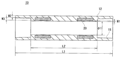
図1に示すこの発明の一実施例である防火区画貫通継手10はソケット型継手である。継手本体12は塩化ビニル、ポリエチレン,ポリブテン,ポリプロピレンあるいはナイロンなど合成樹脂から形成される。
The fire
継手本体12の形状は円筒形であり、長さL1はたとえば150mmであり、内径φ1は図2に示すように、継手10内に差込まれる管16の内径φ2と等しく、たとえば100mmである。その両端部に肉薄の受口18を設け、受口18を設けていない中央部の管壁内に2個の熱膨張材リング20を埋め込む。それらの位置は、たとえば壁14に設けた貫通孔22(図2)の両端部に対応する位置である。
The shape of the
熱膨張材リング20の内側の継手本体12の管壁の厚さW1は管の使用上必要最小限とする。たとえば、排水管の場合であれば汚水による浸食、管内洗浄時の磨耗などを考慮した最小限の厚さとされ、たとえば2mmである。リング20の外側の管壁の厚さW2は防火区画貫通継手10の管壁に強度を持たせるため管16の管壁の厚さtとほぼ等しく、たとえば7.1mmである。熱膨張材リング20の厚さW3はそれの長さとの兼合いで、試験などの結果に基づいて決定される。
The thickness W1 of the pipe wall of the
防火区画貫通継手10は射出成形により形成される。たとえば、溶融した熱膨張材を円筒形の金型に流し込んで、熱膨張材リング20を予め作成しておく。このリング20を継手本体用金型内にセットし、溶融した塩化ビニル樹脂を流し込む。すると、熱膨張材リング20が継手本体12内に埋め込まれる。
The fire prevention
別の製造方法としては、図3に示すように、熱膨張材リング20用の溝24および内層のリング26用の溝28を設けた継手本体12を射出形成で作成する。それらの溝24および溝28の中へ予め作成しておいた熱膨張材リング20および内層のリング26を順番に嵌め込む。そして、熱膨張材リング20を継手本体12と内層のリング26との中に設ける。
As another manufacturing method, as shown in FIG. 3, the
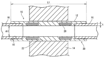
この防火区画貫通継手10を防火区画壁14に設けた貫通孔22に挿入し、その両端部の受口18内へそれぞれ管16を嵌めて接着することにより、管路30を形成する。たとえば、図2の壁14の右側で火災が発生した場合、図4に示すように、その熱により防火区画貫通継手10の右側の熱膨張材リング20が膨張して管路30を塞ぎ、壁14内に断熱層32を形成する。このため、防火区画貫通継手10を設けた壁14は防火区画として、炎や煙などが管路30内を通り壁14の左側へ拡がることを防止する。
This fireproof section through
このように、予め継手本体12内に熱膨張材リング20を埋め込んでおけば、防火区画貫通継手10を貫通孔22内にそのまま挿入することができる。このため、施工時に別部材を管路30に巻き付けるなどの手間が必要なく、施工性に優れる。
Thus, if the thermal
熱膨張材リング20の内側の管壁の厚みを最小限に薄くすると、熱膨張材リング20が膨張する際の管壁の抵抗力が小さく、かつ管壁が熱により軟化し易いので、火災時に熱膨張材リング20は速やかに貫通孔22(管路30)を閉塞することができる。
なお、2個の熱膨張材リング20を継手本体12に設けたが、継手本体12の中央部の長さL2の中央に1個または適当な間隔で3個以上のリングを用いてもよい。
If the thickness of the tube wall inside the thermally
In addition, although the two thermal
熱膨張材リング20を継手本体12内に埋め込んで、リング20の内側に本体壁を残すようにしたが、この内側本体壁(図1のW1の厚みのもの)はなくてもよい。すなわち、熱膨張材リング20が継手本体12の内面に露出するように、リング20を継手本体12内の最も内側に埋め込むこともできる。このようにすると、熱膨張材が露出しているので膨張しやすく、管路30をさらに迅速に遮断することができる。ただし、この場合には熱膨張材リング20に耐水性や耐薬品性などのたとえば排水管としての必要性能を付与する必要がある。この防火区画貫通継手10に必要性能が不足していても、熱膨張材リング20の内側にエポキシ系、ウレタン系およびふっ素系などの樹脂をコーティングして、それらの必要性能を確保するようにしてもよい。
Although the thermal
図5に示すこの発明の他の一実施例である防火区画貫通継手10は図1に示す防火区画貫通継手10とほぼ同じであるが、継手本体12に熱膨張材リング20を1個埋め込んでいる。この防火区画貫通継手10を防火区画床34の貫通孔22に嵌め込み、その両端部の受口18へ管16をそれぞれ挿入し接着することにより、管路30を形成する。これ以外の部分に関しては図1実施例の示す防火区画貫通継手10と同様であるため、説明は省略する。
The fire
この防火区画貫通継手10を防火区画床34内に設けて、たとえば、図5の床34の下側で火災が発生した場合、その熱により防火区画貫通継手10の熱膨張材リング20が膨張して管路30を塞いで、炎や煙などが管路30内を通り床34の上側へ上ってくることを防止する。
For example, when a fire occurs on the lower side of the
なお、熱膨張材リング20の個数は1個であるが、間隔を開けて2個以上設けてもよい。
In addition, although the number of the thermal
10…防火区画貫通継手
12…継手本体
16…管
20…熱膨張材リング
DESCRIPTION OF
Claims (7)
溶融状態で一体化された合成樹脂によって形成される厚肉の中央部と前記中央部の両端部に形成される当該中央部より薄肉の受口とを含み、前記貫通孔に設置される継手本体、および
前記中央部の管壁内部に埋め込まれる熱膨張材を備え、
前記受口の両端は、前記合成樹脂のみからなり、
前記熱膨張材は、火災時に当該熱膨張材の内側の前記合成樹脂を押し潰して前記貫通孔に断熱層を形成することを特徴とする、防火区画貫通継手。 A fire compartment penetrating joint that penetrates the fire compartment through a through hole and joins pipes together,
And a said central portion than in the thin receptacle formed at both ends of the central portion and the central portion of the Ru thick is formed by the integrated synthetic resin in a molten state, the joint body installed in the through hole And a thermal expansion material embedded in the central tube wall,
Both ends of the socket is Ri Do because only the synthetic resin,
The thermal expansion material, and forming an insulating layer in the through hole by crushing the synthetic resin inside of the thermal expansion material in a fire, fire rating through joint.
内層および外層が前記合成樹脂によって形成され、中間層が前記熱膨張材によって形成される3層部、および
前記合成樹脂によって形成され、前記3層部と同じ厚みを有する単層部を含む、請求項1記載の防火区画貫通継手。 The central part is
An inner layer and an outer layer are formed of the synthetic resin, an intermediate layer includes a three-layer portion formed of the thermal expansion material, and a single-layer portion formed of the synthetic resin and having the same thickness as the three-layer portion. Item 1. A fireproof section through joint according to Item 1.
前記熱膨張材、当該熱膨張材の内側の前記合成樹脂、および当該熱膨張材の外側の前記合成樹脂の厚さのそれぞれは、前記中央部の周方向に対して均一の厚さを有する、請求項1ないし4のいずれかに記載の防火区画貫通継手。Each of the thermal expansion material, the synthetic resin inside the thermal expansion material, and the thickness of the synthetic resin outside the thermal expansion material has a uniform thickness with respect to the circumferential direction of the central portion. The fireproof compartment penetration joint according to any one of claims 1 to 4.
少なくとも防火区画の貫通孔内に熱膨張材が位置するように前記防火区画貫通継手の中央部が配置され、当該防火区画貫通継手の受口のそれぞれに管が接続されることによって形成される、防火区画貫通管路。The center part of the fire prevention compartment penetration joint is disposed so that the thermal expansion material is located at least in the through hole of the fire prevention compartment, and a tube is connected to each of the receiving ports of the fire prevention compartment penetration joint. Fire protection section through pipe.
Priority Applications (1)
| Application Number | Priority Date | Filing Date | Title |
|---|---|---|---|
| JP2003316682A JP4549045B2 (en) | 2003-09-09 | 2003-09-09 | Fire compartment penetrating joint |
Applications Claiming Priority (1)
| Application Number | Priority Date | Filing Date | Title |
|---|---|---|---|
| JP2003316682A JP4549045B2 (en) | 2003-09-09 | 2003-09-09 | Fire compartment penetrating joint |
Related Child Applications (1)
| Application Number | Title | Priority Date | Filing Date |
|---|---|---|---|
| JP2007305182A Division JP5008535B2 (en) | 2007-11-27 | 2007-11-27 | Fire compartment penetrating pipe and fire compartment penetrating joint |
Publications (3)
| Publication Number | Publication Date |
|---|---|
| JP2005083483A JP2005083483A (en) | 2005-03-31 |
| JP2005083483A5 JP2005083483A5 (en) | 2008-01-17 |
| JP4549045B2 true JP4549045B2 (en) | 2010-09-22 |
Family
ID=34416505
Family Applications (1)
| Application Number | Title | Priority Date | Filing Date |
|---|---|---|---|
| JP2003316682A Expired - Lifetime JP4549045B2 (en) | 2003-09-09 | 2003-09-09 | Fire compartment penetrating joint |
Country Status (1)
| Country | Link |
|---|---|
| JP (1) | JP4549045B2 (en) |
Families Citing this family (11)
| Publication number | Priority date | Publication date | Assignee | Title |
|---|---|---|---|---|
| JP2007056537A (en) * | 2005-08-24 | 2007-03-08 | Kubota Corp | Drain piping structure and resin drain piping joint |
| JP4903517B2 (en) * | 2006-08-17 | 2012-03-28 | シーシーアイ株式会社 | Fireproof attachment |
| JP2008106936A (en) * | 2006-09-28 | 2008-05-08 | Kubota Corp | Pipe material for piping and drain pipe system |
| JP4994886B2 (en) * | 2007-02-27 | 2012-08-08 | 株式会社クボタ | Drainage piping structure |
| JP4994913B2 (en) * | 2007-03-30 | 2012-08-08 | 株式会社クボタ | Drainage piping structure |
| JP2011102535A (en) * | 2011-01-21 | 2011-05-26 | Kubota Corp | Drain piping joint |
| JP5859042B2 (en) * | 2014-02-25 | 2016-02-10 | クボタシーアイ株式会社 | Drainage pipe fitting |
| KR101619457B1 (en) * | 2014-06-10 | 2016-05-13 | (주)디모스텍 | Foamable Fireproof is Equipped Drainpipe |
| JP6737569B2 (en) * | 2015-03-31 | 2020-08-12 | 積水化学工業株式会社 | Cable protection tube and fireproof structure |
| KR101903691B1 (en) * | 2016-10-21 | 2018-10-04 | 삼성중공업 주식회사 | Flange assembly for pipe and method for installing the same |
| JP6918491B2 (en) * | 2016-12-28 | 2021-08-11 | 積水化学工業株式会社 | Fireproof structure of fixed frame and compartment penetration |
Citations (12)
| Publication number | Priority date | Publication date | Assignee | Title |
|---|---|---|---|---|
| JPH049518Y2 (en) * | 1985-05-31 | 1992-03-10 | ||
| JPH08299487A (en) * | 1995-05-02 | 1996-11-19 | Furukawa Techno Material:Kk | Fire-proof device for long body penetrated part |
| JPH11201382A (en) * | 1998-01-13 | 1999-07-30 | Sekisui Chem Co Ltd | Pipe joint having heat insulation layer, and its manufacture |
| JPH11201383A (en) * | 1998-01-14 | 1999-07-30 | Sekisui Chem Co Ltd | Pipe joint and manufacture thereof |
| JP2001047466A (en) * | 1999-08-10 | 2001-02-20 | Sekisui Chem Co Ltd | Production of foamed layer built-in joint |
| JP2001289363A (en) * | 2000-04-10 | 2001-10-19 | Kubota Corp | Fireproof three-layer pipe |
| JP2002071082A (en) * | 2000-08-28 | 2002-03-08 | Sekisui Chem Co Ltd | Sound absorptive fireproof tube |
| JP2002080612A (en) * | 2000-09-05 | 2002-03-19 | Tosetz Co Ltd | Method of producing thermally expansive molded article, and the molded article |
| JP2002250479A (en) * | 2001-02-22 | 2002-09-06 | Tosetz Co Ltd | Penetration member for fire prevention section |
| JP2002323177A (en) * | 2001-02-26 | 2002-11-08 | Bakuma Kogyo Kk | Fire-proof skeleton penetrating drain pipe unit and its construction method |
| JP2003181373A (en) * | 2001-12-19 | 2003-07-02 | Tokyo Gas Co Ltd | Construction method for preventing disaster for exposed pipeline |
| JP2003214592A (en) * | 2002-10-28 | 2003-07-30 | Funen Akurosu Kk | Joint for fire prevention division penetrating part |
-
2003
- 2003-09-09 JP JP2003316682A patent/JP4549045B2/en not_active Expired - Lifetime
Patent Citations (12)
| Publication number | Priority date | Publication date | Assignee | Title |
|---|---|---|---|---|
| JPH049518Y2 (en) * | 1985-05-31 | 1992-03-10 | ||
| JPH08299487A (en) * | 1995-05-02 | 1996-11-19 | Furukawa Techno Material:Kk | Fire-proof device for long body penetrated part |
| JPH11201382A (en) * | 1998-01-13 | 1999-07-30 | Sekisui Chem Co Ltd | Pipe joint having heat insulation layer, and its manufacture |
| JPH11201383A (en) * | 1998-01-14 | 1999-07-30 | Sekisui Chem Co Ltd | Pipe joint and manufacture thereof |
| JP2001047466A (en) * | 1999-08-10 | 2001-02-20 | Sekisui Chem Co Ltd | Production of foamed layer built-in joint |
| JP2001289363A (en) * | 2000-04-10 | 2001-10-19 | Kubota Corp | Fireproof three-layer pipe |
| JP2002071082A (en) * | 2000-08-28 | 2002-03-08 | Sekisui Chem Co Ltd | Sound absorptive fireproof tube |
| JP2002080612A (en) * | 2000-09-05 | 2002-03-19 | Tosetz Co Ltd | Method of producing thermally expansive molded article, and the molded article |
| JP2002250479A (en) * | 2001-02-22 | 2002-09-06 | Tosetz Co Ltd | Penetration member for fire prevention section |
| JP2002323177A (en) * | 2001-02-26 | 2002-11-08 | Bakuma Kogyo Kk | Fire-proof skeleton penetrating drain pipe unit and its construction method |
| JP2003181373A (en) * | 2001-12-19 | 2003-07-02 | Tokyo Gas Co Ltd | Construction method for preventing disaster for exposed pipeline |
| JP2003214592A (en) * | 2002-10-28 | 2003-07-30 | Funen Akurosu Kk | Joint for fire prevention division penetrating part |
Also Published As
| Publication number | Publication date |
|---|---|
| JP2005083483A (en) | 2005-03-31 |
Similar Documents
| Publication | Publication Date | Title |
|---|---|---|
| JP4549045B2 (en) | Fire compartment penetrating joint | |
| JP5140153B2 (en) | Method and system for sealing an annular gap between a fixed conduit and a pipe, tube or duct made of a thermoplastic material extending into the conduit | |
| EP3682151B1 (en) | Conduit through which at least one pipe or cable extends | |
| KR20100097091A (en) | Fire-stop system for placement in a conduit through which a thermally weakenable pipe extends, method for placing the system and conduit provided with such a system | |
| JP2568656Y2 (en) | Fire protection structure at the penetration of a long fire protection compartment | |
| JPH0651697U (en) | Pipe segment for building heat insulation conduit | |
| JP2023126673A (en) | Pipe assembly insulation and vapor barrier | |
| US6615860B2 (en) | Fire block conduit coupler | |
| JP5008535B2 (en) | Fire compartment penetrating pipe and fire compartment penetrating joint | |
| JP5351387B2 (en) | Drainage piping structure | |
| JP2005083483A5 (en) | ||
| JP5249398B2 (en) | Fire compartment penetrating pipe and fire compartment penetrating joint | |
| JP2019065953A (en) | Joint, piping structure, and manufacturing method of joint | |
| JP6147690B2 (en) | Drainage pipe fitting | |
| JP5384082B2 (en) | Refractory double-layer pipe fittings | |
| JP6873723B2 (en) | Pipe fittings and leg fittings | |
| JP2008131733A (en) | Duct port waterproofing device | |
| JP2003161392A (en) | Thermal expanding annular joint member with fire resistance for fire resisting double layer pipe joint | |
| JP7294961B2 (en) | Collective Joints, Collective Joint Systems, Buildings | |
| JPH10220659A (en) | Sleeve to be arranged in wall through hole, and concrete wall | |
| EP1352191B1 (en) | Fire block conduit coupler | |
| JP3948821B2 (en) | Connecting member for pipe fittings | |
| JP7343447B2 (en) | Piping support and its manufacturing method | |
| JP4030752B2 (en) | Double-layer pipe | |
| JP2005233414A (en) | Hose coupling structure |
Legal Events
| Date | Code | Title | Description |
|---|---|---|---|
| A711 | Notification of change in applicant |
Free format text: JAPANESE INTERMEDIATE CODE: A712 Effective date: 20050707 |
|
| RD02 | Notification of acceptance of power of attorney |
Free format text: JAPANESE INTERMEDIATE CODE: A7422 Effective date: 20050825 |
|
| A625 | Written request for application examination (by other person) |
Free format text: JAPANESE INTERMEDIATE CODE: A625 Effective date: 20060322 |
|
| A521 | Request for written amendment filed |
Free format text: JAPANESE INTERMEDIATE CODE: A523 Effective date: 20071127 |
|
| A977 | Report on retrieval |
Free format text: JAPANESE INTERMEDIATE CODE: A971007 Effective date: 20090424 |
|
| A131 | Notification of reasons for refusal |
Free format text: JAPANESE INTERMEDIATE CODE: A131 Effective date: 20090428 |
|
| A521 | Request for written amendment filed |
Free format text: JAPANESE INTERMEDIATE CODE: A523 Effective date: 20090617 |
|
| A131 | Notification of reasons for refusal |
Free format text: JAPANESE INTERMEDIATE CODE: A131 Effective date: 20091201 |
|
| A521 | Request for written amendment filed |
Free format text: JAPANESE INTERMEDIATE CODE: A523 Effective date: 20100122 |
|
| TRDD | Decision of grant or rejection written | ||
| A01 | Written decision to grant a patent or to grant a registration (utility model) |
Free format text: JAPANESE INTERMEDIATE CODE: A01 Effective date: 20100706 |
|
| A01 | Written decision to grant a patent or to grant a registration (utility model) |
Free format text: JAPANESE INTERMEDIATE CODE: A01 |
|
| A61 | First payment of annual fees (during grant procedure) |
Free format text: JAPANESE INTERMEDIATE CODE: A61 Effective date: 20100706 |
|
| R150 | Certificate of patent or registration of utility model |
Free format text: JAPANESE INTERMEDIATE CODE: R150 Ref document number: 4549045 Country of ref document: JP Free format text: JAPANESE INTERMEDIATE CODE: R150 |
|
| FPAY | Renewal fee payment (event date is renewal date of database) |
Free format text: PAYMENT UNTIL: 20130716 Year of fee payment: 3 |
|
| FPAY | Renewal fee payment (event date is renewal date of database) |
Free format text: PAYMENT UNTIL: 20140716 Year of fee payment: 4 |
|
| S533 | Written request for registration of change of name |
Free format text: JAPANESE INTERMEDIATE CODE: R313533 |
|
| R350 | Written notification of registration of transfer |
Free format text: JAPANESE INTERMEDIATE CODE: R350 |
|
| EXPY | Cancellation because of completion of term |