JP4547091B2 - Slip control article suitable for use in wet and dry conditions - Google Patents
Slip control article suitable for use in wet and dry conditions Download PDFInfo
- Publication number
- JP4547091B2 JP4547091B2 JP2000573547A JP2000573547A JP4547091B2 JP 4547091 B2 JP4547091 B2 JP 4547091B2 JP 2000573547 A JP2000573547 A JP 2000573547A JP 2000573547 A JP2000573547 A JP 2000573547A JP 4547091 B2 JP4547091 B2 JP 4547091B2
- Authority
- JP
- Japan
- Prior art keywords
- stem
- slip control
- control article
- article
- backing layer
- Prior art date
- Legal status (The legal status is an assumption and is not a legal conclusion. Google has not performed a legal analysis and makes no representation as to the accuracy of the status listed.)
- Expired - Fee Related
Links
Images


Classifications
-
- A—HUMAN NECESSITIES
- A63—SPORTS; GAMES; AMUSEMENTS
- A63B—APPARATUS FOR PHYSICAL TRAINING, GYMNASTICS, SWIMMING, CLIMBING, OR FENCING; BALL GAMES; TRAINING EQUIPMENT
- A63B53/00—Golf clubs
- A63B53/14—Handles
-
- A—HUMAN NECESSITIES
- A63—SPORTS; GAMES; AMUSEMENTS
- A63B—APPARATUS FOR PHYSICAL TRAINING, GYMNASTICS, SWIMMING, CLIMBING, OR FENCING; BALL GAMES; TRAINING EQUIPMENT
- A63B60/00—Details or accessories of golf clubs, bats, rackets or the like
- A63B60/06—Handles
-
- A—HUMAN NECESSITIES
- A63—SPORTS; GAMES; AMUSEMENTS
- A63B—APPARATUS FOR PHYSICAL TRAINING, GYMNASTICS, SWIMMING, CLIMBING, OR FENCING; BALL GAMES; TRAINING EQUIPMENT
- A63B60/00—Details or accessories of golf clubs, bats, rackets or the like
- A63B60/06—Handles
- A63B60/08—Handles characterised by the material
-
- A—HUMAN NECESSITIES
- A63—SPORTS; GAMES; AMUSEMENTS
- A63B—APPARATUS FOR PHYSICAL TRAINING, GYMNASTICS, SWIMMING, CLIMBING, OR FENCING; BALL GAMES; TRAINING EQUIPMENT
- A63B60/00—Details or accessories of golf clubs, bats, rackets or the like
- A63B60/06—Handles
- A63B60/10—Handles with means for indicating correct holding positions
-
- A—HUMAN NECESSITIES
- A63—SPORTS; GAMES; AMUSEMENTS
- A63B—APPARATUS FOR PHYSICAL TRAINING, GYMNASTICS, SWIMMING, CLIMBING, OR FENCING; BALL GAMES; TRAINING EQUIPMENT
- A63B60/00—Details or accessories of golf clubs, bats, rackets or the like
- A63B60/06—Handles
- A63B60/14—Coverings specially adapted for handles, e.g. sleeves or ribbons
-
- B—PERFORMING OPERATIONS; TRANSPORTING
- B25—HAND TOOLS; PORTABLE POWER-DRIVEN TOOLS; MANIPULATORS
- B25G—HANDLES FOR HAND IMPLEMENTS
- B25G1/00—Handle constructions
- B25G1/10—Handle constructions characterised by material or shape
-
- B—PERFORMING OPERATIONS; TRANSPORTING
- B32—LAYERED PRODUCTS
- B32B—LAYERED PRODUCTS, i.e. PRODUCTS BUILT-UP OF STRATA OF FLAT OR NON-FLAT, e.g. CELLULAR OR HONEYCOMB, FORM
- B32B27/00—Layered products comprising a layer of synthetic resin
- B32B27/06—Layered products comprising a layer of synthetic resin as the main or only constituent of a layer, which is next to another layer of the same or of a different material
- B32B27/08—Layered products comprising a layer of synthetic resin as the main or only constituent of a layer, which is next to another layer of the same or of a different material of synthetic resin
-
- B—PERFORMING OPERATIONS; TRANSPORTING
- B62—LAND VEHICLES FOR TRAVELLING OTHERWISE THAN ON RAILS
- B62K—CYCLES; CYCLE FRAMES; CYCLE STEERING DEVICES; RIDER-OPERATED TERMINAL CONTROLS SPECIALLY ADAPTED FOR CYCLES; CYCLE AXLE SUSPENSIONS; CYCLE SIDE-CARS, FORECARS, OR THE LIKE
- B62K21/00—Steering devices
- B62K21/26—Handlebar grips
-
- A—HUMAN NECESSITIES
- A63—SPORTS; GAMES; AMUSEMENTS
- A63B—APPARATUS FOR PHYSICAL TRAINING, GYMNASTICS, SWIMMING, CLIMBING, OR FENCING; BALL GAMES; TRAINING EQUIPMENT
- A63B2208/00—Characteristics or parameters related to the user or player
- A63B2208/12—Characteristics or parameters related to the user or player specially adapted for children
-
- A—HUMAN NECESSITIES
- A63—SPORTS; GAMES; AMUSEMENTS
- A63B—APPARATUS FOR PHYSICAL TRAINING, GYMNASTICS, SWIMMING, CLIMBING, OR FENCING; BALL GAMES; TRAINING EQUIPMENT
- A63B49/00—Stringed rackets, e.g. for tennis
- A63B49/02—Frames
- A63B49/08—Frames with special construction of the handle
-
- Y—GENERAL TAGGING OF NEW TECHNOLOGICAL DEVELOPMENTS; GENERAL TAGGING OF CROSS-SECTIONAL TECHNOLOGIES SPANNING OVER SEVERAL SECTIONS OF THE IPC; TECHNICAL SUBJECTS COVERED BY FORMER USPC CROSS-REFERENCE ART COLLECTIONS [XRACs] AND DIGESTS
- Y10—TECHNICAL SUBJECTS COVERED BY FORMER USPC
- Y10T—TECHNICAL SUBJECTS COVERED BY FORMER US CLASSIFICATION
- Y10T24/00—Buckles, buttons, clasps, etc.
- Y10T24/27—Buckles, buttons, clasps, etc. including readily dissociable fastener having numerous, protruding, unitary filaments randomly interlocking with, and simultaneously moving towards, mating structure [e.g., hook-loop type fastener]
- Y10T24/2792—Buckles, buttons, clasps, etc. including readily dissociable fastener having numerous, protruding, unitary filaments randomly interlocking with, and simultaneously moving towards, mating structure [e.g., hook-loop type fastener] having mounting surface and filaments constructed from common piece of material
-
- Y—GENERAL TAGGING OF NEW TECHNOLOGICAL DEVELOPMENTS; GENERAL TAGGING OF CROSS-SECTIONAL TECHNOLOGIES SPANNING OVER SEVERAL SECTIONS OF THE IPC; TECHNICAL SUBJECTS COVERED BY FORMER USPC CROSS-REFERENCE ART COLLECTIONS [XRACs] AND DIGESTS
- Y10—TECHNICAL SUBJECTS COVERED BY FORMER USPC
- Y10T—TECHNICAL SUBJECTS COVERED BY FORMER US CLASSIFICATION
- Y10T428/00—Stock material or miscellaneous articles
- Y10T428/23907—Pile or nap type surface or component
- Y10T428/23979—Particular backing structure or composition
-
- Y—GENERAL TAGGING OF NEW TECHNOLOGICAL DEVELOPMENTS; GENERAL TAGGING OF CROSS-SECTIONAL TECHNOLOGIES SPANNING OVER SEVERAL SECTIONS OF THE IPC; TECHNICAL SUBJECTS COVERED BY FORMER USPC CROSS-REFERENCE ART COLLECTIONS [XRACs] AND DIGESTS
- Y10—TECHNICAL SUBJECTS COVERED BY FORMER USPC
- Y10T—TECHNICAL SUBJECTS COVERED BY FORMER US CLASSIFICATION
- Y10T428/00—Stock material or miscellaneous articles
- Y10T428/24—Structurally defined web or sheet [e.g., overall dimension, etc.]
- Y10T428/24174—Structurally defined web or sheet [e.g., overall dimension, etc.] including sheet or component perpendicular to plane of web or sheet
- Y10T428/24182—Inward from edge of web or sheet
-
- Y—GENERAL TAGGING OF NEW TECHNOLOGICAL DEVELOPMENTS; GENERAL TAGGING OF CROSS-SECTIONAL TECHNOLOGIES SPANNING OVER SEVERAL SECTIONS OF THE IPC; TECHNICAL SUBJECTS COVERED BY FORMER USPC CROSS-REFERENCE ART COLLECTIONS [XRACs] AND DIGESTS
- Y10—TECHNICAL SUBJECTS COVERED BY FORMER USPC
- Y10T—TECHNICAL SUBJECTS COVERED BY FORMER US CLASSIFICATION
- Y10T428/00—Stock material or miscellaneous articles
- Y10T428/24—Structurally defined web or sheet [e.g., overall dimension, etc.]
- Y10T428/2419—Fold at edge
- Y10T428/24198—Channel-shaped edge component [e.g., binding, etc.]
-
- Y—GENERAL TAGGING OF NEW TECHNOLOGICAL DEVELOPMENTS; GENERAL TAGGING OF CROSS-SECTIONAL TECHNOLOGIES SPANNING OVER SEVERAL SECTIONS OF THE IPC; TECHNICAL SUBJECTS COVERED BY FORMER USPC CROSS-REFERENCE ART COLLECTIONS [XRACs] AND DIGESTS
- Y10—TECHNICAL SUBJECTS COVERED BY FORMER USPC
- Y10T—TECHNICAL SUBJECTS COVERED BY FORMER US CLASSIFICATION
- Y10T428/00—Stock material or miscellaneous articles
- Y10T428/24—Structurally defined web or sheet [e.g., overall dimension, etc.]
- Y10T428/24273—Structurally defined web or sheet [e.g., overall dimension, etc.] including aperture
- Y10T428/24322—Composite web or sheet
-
- Y—GENERAL TAGGING OF NEW TECHNOLOGICAL DEVELOPMENTS; GENERAL TAGGING OF CROSS-SECTIONAL TECHNOLOGIES SPANNING OVER SEVERAL SECTIONS OF THE IPC; TECHNICAL SUBJECTS COVERED BY FORMER USPC CROSS-REFERENCE ART COLLECTIONS [XRACs] AND DIGESTS
- Y10—TECHNICAL SUBJECTS COVERED BY FORMER USPC
- Y10T—TECHNICAL SUBJECTS COVERED BY FORMER US CLASSIFICATION
- Y10T428/00—Stock material or miscellaneous articles
- Y10T428/24—Structurally defined web or sheet [e.g., overall dimension, etc.]
- Y10T428/24479—Structurally defined web or sheet [e.g., overall dimension, etc.] including variation in thickness
- Y10T428/24496—Foamed or cellular component
- Y10T428/24504—Component comprises a polymer [e.g., rubber, etc.]
- Y10T428/24512—Polyurethane
-
- Y—GENERAL TAGGING OF NEW TECHNOLOGICAL DEVELOPMENTS; GENERAL TAGGING OF CROSS-SECTIONAL TECHNOLOGIES SPANNING OVER SEVERAL SECTIONS OF THE IPC; TECHNICAL SUBJECTS COVERED BY FORMER USPC CROSS-REFERENCE ART COLLECTIONS [XRACs] AND DIGESTS
- Y10—TECHNICAL SUBJECTS COVERED BY FORMER USPC
- Y10T—TECHNICAL SUBJECTS COVERED BY FORMER US CLASSIFICATION
- Y10T428/00—Stock material or miscellaneous articles
- Y10T428/24—Structurally defined web or sheet [e.g., overall dimension, etc.]
- Y10T428/24942—Structurally defined web or sheet [e.g., overall dimension, etc.] including components having same physical characteristic in differing degree
- Y10T428/24983—Hardness
-
- Y—GENERAL TAGGING OF NEW TECHNOLOGICAL DEVELOPMENTS; GENERAL TAGGING OF CROSS-SECTIONAL TECHNOLOGIES SPANNING OVER SEVERAL SECTIONS OF THE IPC; TECHNICAL SUBJECTS COVERED BY FORMER USPC CROSS-REFERENCE ART COLLECTIONS [XRACs] AND DIGESTS
- Y10—TECHNICAL SUBJECTS COVERED BY FORMER USPC
- Y10T—TECHNICAL SUBJECTS COVERED BY FORMER US CLASSIFICATION
- Y10T428/00—Stock material or miscellaneous articles
- Y10T428/24—Structurally defined web or sheet [e.g., overall dimension, etc.]
- Y10T428/24942—Structurally defined web or sheet [e.g., overall dimension, etc.] including components having same physical characteristic in differing degree
- Y10T428/24992—Density or compression of components
-
- Y—GENERAL TAGGING OF NEW TECHNOLOGICAL DEVELOPMENTS; GENERAL TAGGING OF CROSS-SECTIONAL TECHNOLOGIES SPANNING OVER SEVERAL SECTIONS OF THE IPC; TECHNICAL SUBJECTS COVERED BY FORMER USPC CROSS-REFERENCE ART COLLECTIONS [XRACs] AND DIGESTS
- Y10—TECHNICAL SUBJECTS COVERED BY FORMER USPC
- Y10T—TECHNICAL SUBJECTS COVERED BY FORMER US CLASSIFICATION
- Y10T428/00—Stock material or miscellaneous articles
- Y10T428/31504—Composite [nonstructural laminate]
- Y10T428/31826—Of natural rubber
- Y10T428/3183—Next to second layer of natural rubber
Description
【0001】
発明の分野
本発明は、柔らかで手触りが良く、摩擦特性が高く、湿潤状態および乾燥状態に高性能である、滑り制御物品に関する。
【0002】
発明の背景
補強されたグリップおよび耐滑り面の開発は、一般に物品の材料および表面の位相幾何学を中心とする。共通の材料は、天然および合成ゴム、スチレンブロックコポリマー、ラテックス、エチレン酢酸ビニル、エチレンプロピレンゴム、ポリウレタン、ポリエステルコポリマー、ポリイミドなどである。表面の位相幾何学は滑らかなものから誇張された掴み構造を有するものまでに及ぶ。
【0003】
米国特許第3,585,101号は、アルミニウム、真鍮、プラスチックなどの柔らかで、可鍛性、可撓性があり、改良された掴み面を提供するためにぎざぎざ模様が刻まれた材料の薄いシートを開示している。シートは接着剤を使用して硬質物体に適用される。
【0004】
米国特許第4,488,918号は、プラスチックフィルムに同時押出され接着された第2の熱可塑性材料で形成される硬質の山および谷が間隔をあけて無作為にある滑り止め面を有するプラスチックフィルムを開示している。表面は比較的高く鋭い不規則なプラスチックの山と谷のパターンを有し、また十分に鋭く硬く粗いため他の表面を機械的に掴むことができる。
【0005】
米国特許第5,234,740号は、構造面を有する滑り制御面を開示している。構造面は、突起、一般には三角錐の突起の配列を含む。この特許は、ソフトボールのバット、ゴルフクラブ、テニスラケット、ラケットボールラケット、スカッシュラケット、バドミントンラケットなどの競技用具の他に工具の取っ手に適用されてもよいことを開示している。
【0006】
発明の概要
本発明は、柔らかで手触りが良く、摩擦特性が高く、湿潤および乾燥の両方の状態で掴みの性能が高い改良された掴み面に関する。掴み面は、熱可塑性エラストマーから作られる様々な形状の可撓性がある直立するステムの配列を有する柔らかい微細構造面である。ステムの大きさ、配置間隔および可撓性、またステムの配列のパターン、さらにエラストマー材料の特性は、これら全てが表面の柔らかい手触り、制振作用、および乾燥および湿潤状態における掴み性能を提供している。本発明の滑り制御面の様々な実施態様は、微小流路、吸収剤層および親水性/疎水性領域を含んでもよく、これらは全て流体を直立するステムから離れるように誘導し、ステムを乾燥したままであるようにして湿潤状態でも高い摩擦性能を提供する。
【0007】
本発明の滑り制御物品は、別の物品に適用できるラップなどのシート構造に形成されてもよい。あるいは、滑り制御物品は、ゴルフクラブ、野球用バット、ラケット、自転車のハンドル、運動用具、家庭用品、建設用機械、外科用器機、さらにプールサイド、飛び込み台、浴槽の滑り止め面を含む様々な成形または製造された物品に組み込まれてもよい。
【0008】
一実施態様において、滑り制御物品は1平方センチメートルあたり少なくとも15.5本(1平方インチあたり100本)、より一般的には1平方センチメートルあたり少なくとも54本(1平方インチあたり350本)のステムの配列を有する第1面と、そして第2面とを有する。直立するステムの外面の少なくとも一部はエラストマー材料である。ステムのアスペクト比(ステムの高さ:ステムの直径)は少なくとも1.25であり、好ましくは少なくとも1.5であり、より好ましくは少なくとも2.0であり、最も好ましくは3.0より大きい。第1面の静摩擦係数は、乾燥時には少なくとも0.6であり、湿潤時には乾燥時の静摩擦係数からの変動が20%内である。したがって、水が存在するとき摩擦特性は実質的に低下することはない。第1面の剥離強さおよび引張強さは、別の滑り制御物品と係合するとき実質的にゼロである。
【0009】
一実施態様において、エラストマー材料を含む直立するステムの配列は、第2面上にも形成される。第2面の静摩擦係数は、乾燥時には少なくとも0.6であり、湿潤時には乾燥時の静摩擦係数の20%内である。第2面の剥離強さおよび引張強さは、別の滑り制御物品と係合するとき実質的にゼロである。
【0010】
他の実施態様において、静摩擦係数は、乾燥時には少なくとも1.0または少なくとも2.0である。別の滑り制御面と約53グラム/6.45cm2の圧力で係合するとき、第1面の動的剪断強さが少なくとも23,268ダイン/cm2(5.4オンス/in2)であり、好ましくは43,090ダイン/cm2(10オンス/in2)より大きく、より好ましくは少なくとも77,562ダイン/cm2(18オンス/in2)であり、最も好ましくは少なくとも107,725ダイン/cm2(25オンス/in2)である。高い剪断力は本質的にはエラストマー材料の摩擦特性によるものであり、機械的締結具などでのステムの機械的連動によるものではない。
【0011】
裏材層は、滑り制御物品の用途によっては、補強ウェブ、気泡層、実質的に非弾性ポリマー層、または接着剤あるいは発泡接着剤層などの1つまたはそれ以上の層であってもよい。裏材層は、弾性であっても非弾性であっても、厚くても薄くても、多孔性であっても非孔性であっても、接着剤層が有っても無くてもよい。一実施態様において、非エラストマー裏材層は、直立するステムの一部を形成してもよい。裏材層は任意に極めて薄くてもよいため、本発明の滑り制御物品は非常に薄いラップまたは軽量の掴みの用途としての使用に適したグリップテープとして構成されてもよい。あるいは、裏材層は成形された、押出された、または製造された物品の一部であってもよい。
【0012】
発明の詳細な説明
図1は、本発明による滑り制御物品20の側面断面図である。物品20は、直立するステム26の配列を有する第1面24を有する裏材層21を含む。ステムは規則的または不規則な配列に配置されてもよい。ステムの様々なパターン(六角形、斜線、正弦曲線など)が使用されてもよい。直立するステム26はエラストマー材料で構成される。直立するステム26の全外面はエラストマー材料である。図1の実施態様において、裏材層21はエラストマー材料の直立するステム26と一体成形される。裏材層21と直立するステム26の組み合わせはステムウェブと呼ばれることがある。例証される実施態様は、ステム26を略円筒形として示し、ステム26の側面は一般に僅かにテーパー35になっており金型から取り外し易くしている。切頭円錐または切頭角錐、矩形、半球、正方形、六角形、八角形、ガムドロップ(gum drop)など、様々な非円筒形の形状も利用されうる。
【0013】
本発明の滑り制御物品20は、構造を団結するためにエラストマー材料で構成される直立するステム26および裏材層21を本質的に必要とする。しかしながら、裏材層21のエラストマー特性は、滑り制御物品20がグリップ包装として使用される場合など、用途によっては全ての要求を満たすわけではない。したがって、追加の裏材層22、34、36は、裏材層21を補強するために第2面25に任意に適用される。追加の裏材層22は、滑り制御物品20を固定および補強し、他の様々な機能と同様に引張に抵抗し引裂抵抗を高める。本発明の滑り制御物品20を別の面に取り付けるために、接着剤層34および剥離ライナー36が任意に提供される。本明細書で使用されるように、裏材層は、直立するステムを支持する1つまたはそれ以上の層を有するアセンブリを指すが、一般にはこれらの層の多くて1つは直立するステムと一体成形される。
【0014】
裏材層の厚さは一般には、約0.05〜約0.38mm(0.002in〜0.015in)である。いくつかの例において、裏材層は押出しの間に一枚の布帛など補強ウェブと結合させるのに十分な厚さであり、引裂抵抗および引張強さをさらに与える。滑り制御物品が可撓性支持体に縫い止められているとき、補強ウェブは特に有用である。裏材層は発泡または固体ポリマー材料であってもよい。一実施態様において、裏材層は、繊維材料または織物または不織の布帛スクリムの層などの多孔性および/または吸収剤層を含んでもよい。多孔性材料は水分を吸収するおよび/または水分を直立するステムから離れるように誘導するのに有用である。一実施態様において、裏材層は、滑り制御物品のネッキングまたは引張を防ぐ実質的に非弾性の層を含む。
【0015】
滑り制御物品を一体に保つために裏材層にエラストマー材料と十分に融和性があるのが望ましい。好適な裏材層材料は、熱可塑性ポリウレタン、ポリ塩化ビニル、ポリアミド、ポリイミド、ポリオレフィン(例、ポリエチレンおよびポリプロピレン)、ポリエステル(例、ポリエチレンテレフタレート)、ポリスチレン、ナイロン、アセタール、ブロックコポリマー(例、テキサス州ヒューストンのShell Chemical CompanyよりKRATON(登録商標)の名称で入手可能なエラストマーセグメントを含むポリスチレン材料)、ポリカーボネート、熱可塑性エラストマー(例ポリオレフィン、ポリエステル、またはナイロンのタイプ)およびコポリマー、およびこれらのブレンドを含む。また熱可塑性材料は、充填剤、繊維、帯電防止剤、滑剤、潤滑剤、発泡剤、界面活性剤、顔料、染料、カップリング剤、可塑剤、沈殿防止剤、親水性/疎水性添加剤などを含むがこれらに限定はされない添加剤も含んでもよい。
【0016】
任意の接着剤層は一般には、滑り制御物品が適用される支持体物品に結合させるために選択される、感圧接着剤、熱硬化性または熱可塑性接着剤、放射線硬化接着剤、溶液型接着剤、およびこれらのブレンドなどの接着剤を含む。接着剤はフィラメントを含んでもよい。裏材層は任意に積層できる、または接着剤を染み込ませることができる。本発明に有用な一接着剤は、Minnesota Mining and Manufacturing Companyより入手可能なAdhesive Transfer Tape 950である。多くの好適なエポキシ、ウレタン、合成または天然ベースのゴムおよびアクリル接着剤も、この目的で市販されており入手可能である。用途によっては、接着剤は滑り制御物品を表面に剥離可能に結合しても、永久に結合してもよい。
【0017】
図1Aは、図1に概ね説明されている追加裏材層22、34、36を除いた両面滑り制御物品20’の断面図である。物品20’は、直立するステム26’の配列を第1面24’と第2面25’の両方に有する裏材層21’を含む。直立するステム26’は単一のエラストマー材料で構成される。図1Aの実施態様において、裏材層21’はエラストマー材料の直立するステム26’と一体成形される。別の実施態様において、上部分と下部分とは、2つの異なるエラストマー材料から同時押出されてもよい。本発明による両面滑り制御物品は、開示される様々な実施態様から形成されてもよい。
【0018】
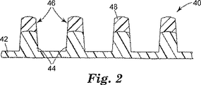
図2は、本発明による別の滑り制御物品40の側面断面図である。裏材層42はステム46の下部分44を画定する。ステム46の上部分48はエラストマー材料で構成される。裏材層42およびステムの下部分44は、滑り制御物品40の用途に応じて、エラストマーまたは非エラストマーの様々な材料で構成されてもよい。最低限、上部分48の外面はエラストマー材料である。一実施態様において、ステム44の上部分48は疎水特性を有する。疎水特性は、上部分48を疎水性材料で構成することによって、または上部分48が疎水特性を有するように処理することによって得られうる。無極性液体との接触を含む用途には、ステム46の上部分48は疎水特性を有するように処理されてもよい(例、コロナ処理)。
【0019】
図3は、本発明に従って同時押出によって形成された別の代替の滑り制御物品50の側面断面図である。裏材層52は中央領域54に突出し、エラストマーステム56に構造的一体性を追加する。裏材層52は一般に剛性ポリマー材料である。
【0020】
図3Aは、本発明に従って同時押出によって形成された代替の滑り制御物品50’である。ステム56’および裏材層52’はエラストマー材料で構成される。ステム56’は追加の裏材層53’の中央領域54’を通って突出する。追加の裏材層53’によって構造的安定性、疎水性/親水性特性、あるいは様々な他の機能が得られうる。一実施態様において、追加の裏材層53’はステム56’を構成するのに使用されるものとは異なる特性を有するエラストマー材料であってもよい。
【0021】
図4は、吸収剤層76と流体連通し裏材層74を通る複数の孔72を組み込んだ滑り制御物品70の側面断面図である。吸収剤層76はエラストマーステム78から水分を引き出し、湿潤状態において優れた摩擦特性を維持する。
【0022】
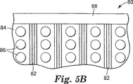
図5Aおよび図5Bは、裏材層84上で直立するエラストマーステム86の間に微小流路82を組み込んだ滑り制御物品80を例示している。微小流路82は毛管力を利用して駆動力の方向に流体を迅速に移動させる。吸収剤層88は裏材84の第1面90に沿って配置され、駆動力を提供する。あるいは、駆動力はステム86の重量および/または親水性部分であってもよい。
【0023】
本発明の滑り制御物品が湿潤および乾燥の両方の状態において非常に優れた摩擦特性を有するように、多くの構造が組み合わされる。図6は、ステム64の疎水性先端62上に存在する個々の水滴60の略図である。水滴60は、滑り制御物品66を振るまたは握ることによってステム64から容易に取り除かれる。水の再分配もまたステムの密度により影響される。
【0024】
大量の水60の沈着により、ステム64の基部において液体が分配されることになり、このとき図7に示すように先端62は乾燥したままである。水または他の極性液体が滑り制御物品66の表面上に沈着するとき、ステム64の先端62は熱可塑性エラストマーポリマーの疎水性の性質のため曝露されたままである。裏材層を親水性材料で構成することで、水60を先端62から離す助けになる。
【0025】
直立するステム64は、ステムのエラストマー材料の摩擦特性のために、主として他の表面とかみ合う。摩擦性能はステム64が他の表面に突出することを要求しない(すなわち、機械的係合は必要ない)。したがって、軟質材料および硬質材料の両方と摩擦接触しうる。
【0026】
本発明の滑り制御物品により、最小の圧力で、別の滑り制御物品と係合するとき、高い剪断力が得られる。直立するステムが可撓性の高いエラストマー材料から実質的に構成されるため、高い剪断力は機械的締結具などでのステムの機械的連動からは得られない。むしろ直立するステムの摩擦特性は、2つの滑り制御物品が互いに係合するとき、ステムの大きさ、ステムの密度、およびステムのパターンによって高められる。可能な用途としては、滑り制御物品を含む表面を掴むように本発明の滑り制御物品が配置されたグローブがある。
【0027】
直立するステムは連動しないため、本発明の滑り制御物品の剥離力および引張力は、同じまたは類似のステムウェブ構造物と係合するときには実質的にゼロである。この特性は、使用者は一般に、滑り制御物品により生じた剥離力または引張力を克服することなく、掴んだ品物を自由に素早く解放できなければならないため、本発明の滑り制御物品を握る目的で安全に使用するために重要である。例えば、本発明の滑り制御物品は自転車のハンドルを包むことも、自転車に乗るときに使用するグローブに適用することもできる。使用者が自転車のハンドルを握るとき、2つの滑り制御物品が係合し、最小の圧力で剪断作用において優れた滑り制御特性を提供する。しかしながら、実質的にゼロである剥離力および引張力によって、使用者が2つの滑り制御物品から実質的にゼロの抵抗でハンドルを解放できる。
【0028】
本発明の滑り制御物品の柔らかな手触りは、エラストマー材料の性質およびステムの幾何学的形状による。エラストマー材料のショアー硬度は好ましくは約70D未満であり(Estane(登録商標)58091)、より好ましくは約90A未満であり、最も好ましくは約60A未満である。引張弾性率は、好ましくは約12MPa未満であり、より好ましくは約6MPa未満であり、最も好ましくは約4MPa未満である。ステムの高さ、ステムの直径、およびステム間の距離(ステムの幾何学的形状と呼ぶ)は、表面上で柔らかな手触りとなるための重要な要因である。一般に、長いステムはその可撓性により手触りが柔らかくなる。ステムの間隔に関しては、指先の触覚の圧点間の平均距離は、約1.27mm(0.050in)である。対象間の距離が触覚の圧点間の距離の半分未満であるとき、表面上の突起を区別するのが困難になる。したがって、最良の手触りは、一般にはステムの密度が可能な限り高いステムウェブによって得られる。ステムの密度が310本/cm2(1平方インチあたりステム2,000本)を超えるものであると、皮膚に接触する際、独特の柔らかさと心地よい手触りが得られる。
【0029】
再度図1を参照すると、滑り制御物品の性能を最適化するためにステムは実質的に直立する必要がある。ステムはステムの直径およびエラストマー材料の性質によって直立状態が保持される。直立するステムの高さ28は、一般に約0.254mm〜約1.27mm(0.010in〜約0.050in)の範囲であり、より一般には約0.51mm〜約1.02mm(0.020in〜0.040in)である。隣接するステム26との間の離隔距離または間隙30は、一般的には約0.254mm〜約2.54mm(0.01in〜0.1in)であり、より一般的には約0.46mm〜約0.84mm(0.018in〜0.033in)である。ステム26の最大横断直径29は約0.076mm〜約0.76mm(0.003in〜約0.030in)である。ステム26は、少なくとも1平方センチメートルあたり15.5本(1平方インチあたり100本)、より一般には1平方センチメートルあたり約54本〜1平方センチメートルあたり約1550本(1平方インチあたり350本〜1平方インチあたり約10,000本)の密度で裏材上に配置される。
【0030】
ステムのアスペクト比は少なくとも1.25であり、好ましくは少なくとも1.5であり、より好ましくは少なくとも2.0であり、最も好ましくは3.0より大きいが、3.0を超えるアスペクト比はいくつかの用途において可能である。アスペクト比は、ピンの高さ対最大横断寸法の比率を表す。円形断面を有するピンに関しては、最大横断寸法はピンの直径である。
【0031】
図8は、本発明による滑り制御面102を組み込んだ典型的な物品100の斜視図である。物品100は一方の端に開口部104を有し、ゴルフクラブ、野球用バット、ハンドルなど様々な構造物に取り付けるのに好適な形成されたグリップである。物品100は射出成形、異形押出、ロール押出成形(roll extrusion forming)など様々な工程によって作られてもよい。
【0032】
エラストマー材料
エラストマー材料は、G. Holden et al.の「Thermoplastic Elastomers」,(第2版、1996年)に記述されるような流されて成形されうる状態に加熱されうる熱可塑性エラストマーであってもよい。2つまたはそれ以上の異なる熱可塑性エラストマー材料を積層されたまたはブレンドされた形で使用し、滑り制御物品の部分を画定することもまた本発明の範囲内である。
【0033】
使用される「エラストマー」または「エラストマーの」という用語は、ゴムのそれと類似のレジリエンス特性を有するゴムまたはポリマーを表す。特に、エラストマーという用語は、実質的に伸ばされ、次いでエラストマーを伸ばす応力を解放すると元の寸法に戻る材料の特性を反映する。全ての場合において、エラストマーは少なくとも10%伸長でき(厚さ0.5mmで)、より好ましくは少なくとも30%伸長でき、2秒間伸長を保持した後で1分間の解放時間の後に、少なくとも50%回復して戻る事ができなければならない。より一般的には、エラストマーは弾性限度を超えずに25%伸長されることができる。いくつかの場合において、エラストマーは引裂かれずまたは組成物の弾性限度を超えずに元の寸法の300%あるいはそれ以上伸長されることができる。エラストマーは一般に、弱い応力およびその応力の解放によって実質的に変形された後、室温で迅速に初めの寸法および形状に戻る高分子材料としてASTM D883−96にあるようにこの弾性を反映するように特徴付けられている。ASTM D412−98Aはエラストマー特性を評価するために張力におけるゴム特性をテストするための適切な手順でありうる。
【0034】
いくつかの用途には、熱硬化性エラストマーが使用されてもよい。一般に、このような組成物は、硬化に際して一体網状構造または構造を形成する比較的高分子量の配合物を含む。硬化は、化学硬化剤、触媒、および/または照射を含む様々な方法によって行われてもよい。
【0035】
材料の最終的な物理的特性は様々な要因の機能であり、特に:平均ポリマー分子の数および量(number and weight average polymer molecular weights);エラストマーの補強領域(硬質セグメント)の融点または軟化点(例えば、ASTM D1238−86によって決定されうる);硬質セグメント領域を含むエラストマー組成物の重量パーセント;エラストマー組成物の強化または軟質セグメント(低Tg)部分;架橋密度(架橋間の平均分子量);および添加剤または補助剤の性質およびレベル、など。
【0036】
エラストマーのクラスの例には、アニオントリブロックコポリマー、ポリオレフィンをベースとする熱可塑性エラストマー、ハロゲン含有ポリオレフィンをベースとする熱可塑性エラストマー、動的加硫エラストマー−熱可塑性物質のブレンドをベースとする熱可塑性エラストマー、ポリアミドまたはポリイミドをベースとする熱可塑性エラストマー、イオノマー熱可塑性エラストマー、ポリマーネットワークに相互貫入する熱可塑性エラストマー中の水素化ブロックコポリマー、カルボカチオン重合による熱可塑性エラストマー、スチレン/水素化ブタジエンブロックコポリマーを含むポリマーブレンド、およびポリアクリル酸エステルをベースとする熱可塑性エラストマーが含まれる。エラストマーのいくつかの特定の例としては、天然ゴム、ブチルゴム、EPDMゴム、ポリジメチルシロキサンなどのシリコーンゴム、ポリイソプレン、ポリブタジエン、ポリウレタン、エチレン/プロピレン/ジエンターポリマーエラストマー、クロロプレンゴム、スチレン−ブタジエンコポリマー(ランダムまたはブロック)、スチレン−イソプレンコポリマー(ランダムまたはブロック)、アクリロニトリル−ブタジエンコポリマー、これらの混合物およびこれらのコポリマーが挙げられる。ブロックコポリマーは線状、放射状、または星の形状であってもよく、またジブロック(AB)またはトリブロック(ABA)コポリマーまたはこれらの混合物であってもよい。これらのエラストマーを互いにまたは非エラストマーとブレンドすることもまた考えられる。ブロックコポリマー(例、エラストマーセグメントを含むポリスチレン材料)を含む市販の入手可能なエラストマーは、テキサス州ヒューストンのShell Chemical CompanyよりKRATON(登録商標)の名称で入手可能である。
【0037】
製造方法
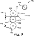
図9に説明される工程は、1つまたはそれ以上の層の溶融熱可塑性材料154を金型156に押出すために適応される押出機または押出ダイ152を含む3つのロールを竪形に積重ねた成形装置150を示す。この場合、金型156はロール158であり、溶融熱可塑性材料154がロール158の円筒形表面上を通過するときそこに移すための所望の表面模様をその外側円筒形面に有する。説明される実施態様において、ロール158の表面は、同様の複数の直立するステム162を形成するために適応される複数の配列されるキャビティ160を有する。キャビティは、熱可塑性材料154から、好適な表面ステム構造を形成するために要求されるように配列され、要求される寸法および形状に作られてもよい。一実施態様において、溶融熱可塑性材料154の十分な追加量が金型156に押出され、裏材層の一部を形成する(図1および図3を参照)。
【0038】
ロール158は回転可能であり、対向するロール168と共にニップ166を形成する。ロール158と対向するロール168との間のニップ166は、溶融熱可塑性材料154をキャビティ160に流すのを助け、その上に均一の裏材層を提供する。ニップ166を形成する間隙の間隔は、熱可塑性材料154の裏材層の予め決められた厚さを形成するのを助けるために調整されうる。任意に、裏材層164は同時にニップ166に運ばれる。エラストマー材料の組成物および直立するステム162の幾何学的形状によっては、裏材層164滑り制御物品172を金型156から能率的に取り除くのに有用でありうる。
【0039】
図9に説明されるように、滑り制御物品172はロール158を出た後に第3ロール170横切ってもよい。この工程において、3つのロール158、168、170全ての温度は、熱可塑性材料154の所望の冷却を達成するために選択的に制御されてもよい。第3ロール170もまた、滑り制御物品172が横切る経路をさらに画定する役割を果たす。
【0040】
金型158は、連続加工(テープ、円筒形ドラム、またはベルトなど)または回分加工(射出成形または圧縮成形など)のいずれかに使用されるタイプでありうる。直立するステム162を形成するために金型158を作るとき、金型158のキャビティ160は孔あけ、機械加工、レーザー孔あけ、水噴射機械加工、注入成形、エッチング、打抜き、ダイヤモンド旋削、型彫り、ローレット切りなどのいずれかの好適な方法で形成されてもよい。キャビティの配置は、滑り制御物品の間隔および配向を決定する。ステム162の形状は一般に、キャビティ160の形状に応じる。金型キャビティは、熱可塑性材料をキャビティに注入するのを促進するために溶融熱可塑性材料が適用される表面の反対側のキャビティの端において開いていてもよい。キャビティが閉じていると、キャビティに真空状態が適用され、溶融熱可塑性材料がキャビティ全体を実質的に満たしうる。あるいは、閉じたキャビティは、形成されるステム構造の長さよりも長く、注入された材料はキャビティ内の空気を圧縮できる。金型キャビティは、そこから表面ステム構造を剥離し易いように設計されるべきであり、したがって斜めの側壁または剥離塗料(テフロン材料層など)をキャビティ壁に含んでもよい。また、金型表面は金型から熱可塑性裏材層を剥離し易くするために剥離塗料をその上に含んでもよい。いくつかの実施態様において、キャビティはロールの表面に応じて斜めでありうる。
【0041】
金型は硬質または可撓性の好適な材料から作られうる。金型部品は、金属、スチール、セラミック、ポリマー材料(シリコーンゴムなど熱硬化性および熱可塑性ポリマーを含む)またはこれらの組み合わせで作られうる。金型を形成する材料は、裏材層および表面の地形を形成するのに使用される特定の流動性がある熱可塑性材料に関連する熱エネルギーに耐える十分な一体性および耐久性がなければならない。さらに、金型を形成する材料は、キャビティが様々な方法で形成され、安価で、寿命が長く、許容できる質の材料を一貫して作り、様々な加工上のパラメーターが可能であるのが好ましい。
【0042】
溶融熱可塑性材料は金型キャビティ内にさらに金型の表面上に流され、被覆材料の層を形成する。溶融熱可塑性材料の流れを促進するために、熱可塑性材料は一般には適切な温度まで加熱され、次いでキャビティに塗布されなければならない。この塗布技術は、カレンダー被覆、キャストコーチング、フローコーチング、しごき塗、押出、グラビア塗布、ナイフ塗布、吹付塗などいずれの従来の技術であってもよい。図9に、単一押出機および押出ダイの配置が示されている。しかしながら、2つ(またはそれ以上)の押出機および関連のダイを使用することで、複数の熱可塑性材料のニップ166に同時に押出し、マルチコンポーネント(multi−component)(多層またはマルチブレンド)積層被覆材料を達成することができる。
【0043】
溶融熱可塑性材料154の金型158への流れは、対向するロール168の間の加圧によって促進されてもよい。裏材層164が多孔性材料を含む場合、3つのロールを竪形に積重ねた成形装置150は溶融熱可塑性材料154の浸透度を制御する。この方法において、溶融熱可塑性材料154の量は、裏材層164の表面被覆をかろうじて浸透するように制御され、裏材層164をほぼ封入するように熱可塑性材料154の挿入と反対側の多孔性裏材層164を浸透するように制御されうる。溶融熱可塑性材料154の多孔性裏材層164への浸透は、溶融熱可塑性材料154の温度、ニップ166における熱可塑性材料154の量、および/または金型キャビティの線速度に関連する押出流量によって制御されてもよい。
【0044】
溶融熱可塑性材料154が金型キャビティ160の中および金型表面156の上に塗布された後、熱可塑性材料は冷却され凝固し、その上に所望の外面地形を形成する(例、直立するステム162)。凝固された熱可塑性材料は次いで金型158から分離される。熱可塑性材料154は、凝固すると収縮することが多く、これによって材料(例、表面ステム構造および裏材層)および一体フィルム層を金型から剥離し易くなる(図1を参照)。金型の一部または全部は、表面ステム構造および裏材層の凝固を助けるために冷却されてもよい。冷却は水、押込空気、伝熱液体、またはその他の冷却工程を使用することにより達成される。
【0045】
射出成形などのいくつかの成形工程は、熱硬化エラストマーポリマーを利用してもよい。溶融材料として熱硬化樹脂が使用される場合、樹脂は未硬化または未重合状態で液体として金型に塗布される。樹脂が金型に塗布された後、樹脂が固体となるまで重合または硬化される。一般に、重合工程は、重合を促進するために硬化時間またはエネルギー源への曝露のいずれか、または両方を含む。エネルギー源は、提供される場合、熱または電子ビーム、紫外線、または可視光線などの放射線エネルギーでありうる。樹脂は凝固した後、金型から取り除かれる。いくつかの例において、表面ステム構造が金型から取り除かれた後に熱硬化樹脂の重合または硬化がさらに望まれてもよい。好適な熱硬化樹脂の例として、メラミン、ホルムアルデヒド樹脂、アクリル酸樹脂、エポキシ樹脂、ウレタン樹脂などが挙げられる。少なくとも一方の側に直立するステム構造を有する裏材層の構成は、米国特許第4,290,174号(Kalleberg)、同第5,077,870号(Melbye et al.)、および同第5,201,101号(Rouser et al.)に開示されるように、射出成形または異形押出によって実現されうる。
【0046】
静摩擦係数および動摩擦係数を測定する試験手順
各フィルムのサンプルの静摩擦係数および動摩擦係数をペンシルベニア州フィラデルフィアのThwing−Albert Instrument Companyより入手可能なThwing−Albert Model 225−1 摩擦/剥離テスターで測定した。装置の操作はThwing−Albert使用説明書、摩擦/剥離テスター、型番号225−1、1994年5月改訂、Software第2.4版に明記されている。この静摩擦係数の分析は、加重された5.08cm×5.08cm(2in×2in)の滑り制御物品のサンプルを、ニューヨーク州マンハッタンのToray Ultrasuede Americaより入手可能なUltrasuede(登録商標)HPという名称で販売されている人工皮革に対して動かすのに必要とされる水平方向の力を測定した。
【0047】
摩擦テスト用試験品は5.08cm×5.08cm(2in×2in)の滑り制御物品のサンプルを5.08cm×5.08cm(2in×2in)の金属テスト用そり(metal test sled)に固定することで用意された。テスト用試験品を、ミネソタ州セントポールのMinnesota Mining and Manufacturing Companyより入手可能なSCOTCH9851などの両面感圧接着剤でそりに取り付けた。金属テスト用そりの重さは500gであった。ブロックの上に500gさらに加重し、総重量を1000gとした。
【0048】
摩擦テスト用の人工皮革サンプルを用意するために、約10.16cm×30.48cm(4in×12in)のサンプルを金属板にSCOTCH9851などの両面感圧接着テープで固定し、テスト中サンプルが動いたりしわがよらないようにした。
【0049】
サンプルが接着された金属板を金属プラテン(platen)の試験面に用意されたばね挟みでしっかりと留めた。底部にフィルムのサンプルを有する金属テスト用そりと総重量が1000gとなるように重量を追加して布帛の上に配置し、分速5.1cm(2in)で10秒間使用説明書に明記されている指示に従って布帛上を横切って引っ張った。次いで静摩擦係数を機械で計算し、ここでサンプル上で滑り量を生じる測定された水平方向の力を1000gのそりの通常の力で割った。各摩擦テスト用サンプルおよび滑り制御物品に関して少なくとも5つの測定が記録された。算術平均を摩擦/剥離テスターで計算した。
【0050】
動的剪断強さの試験方法
動的剪断強さをI−mass剥離テスターで測定した。テスターを180°の剥離状態にした。約3.8cm×12.7cm(1.5in×5in)のステムウェブを3M 404などの両面テープを使用して取り付け、厚さ約1.6mm(1/16in)、6.35cm×22.9cm(幅2.5in×長さ9in)のアルミニウム試験パネルの中心に長さ方向に取り付けた。同様に、約2.54cm×2.54cm(1in×1in)のステムウェブのサンプルを、厚さ約1.6 mm(1/16in)、6.35cm×22.9cm(幅2.5in×長さ9in)のアルミニウム試験パネルの中心に取り付けた。次いでパネルを互いに接触させて各サンプルのステムと共に配置した。デジタルキャリパーゲージを使用してアルミニウムパネルを含み圧力を全く加えずに2つのサンプルの係合する厚さを測定した。上側パネルの重さは約53gであった。
【0051】
I−massテスターの可動プラットホームに、ステムウェブのより大きいサンプルを有するアルミニウムパネルをステムウェブの側を上にして取り付けた。ステムウェブが係合位置にあるように約2.54cm×2.54cm(1in×1in)のステムウェブのサンプルを有するアルミニウムパネルを上部に配置した。フォースゲージ(force gauge)から最も遠い端にあり、上側パネル上のサンプルが下側のサンプルを通って引かれるように、ステムウェブを配置した。係合する組の上に、係合された厚さよりも約0.13mm〜0.254mm(0.005〜0.010in)厚い間隙でバーを配置した。このバーは、2つのステムウェブのサンプルを係合させるために過度の圧力を加えずにサンプルが外れないように設計されている。フォースゲージが可動プラットホームと真直ぐに平行な力を測定するように、上側のアルミニウムパネルの端をフォースゲージの適所に取り付けた。
【0052】
I−massテスターの均合をとり、ゼロの目盛りに合わせ、平均2秒測定するように調節した。間隔を置いたバーが平均2秒間ステムウェブのサンプルの直上にあるように、バーの位置を調節した。プラットホームの割合を30.5cm/分(12in/分)に設定した。各サンプルの山、谷、および平均の力を測定した。各サンプルを3回テストし、平均値を計算した。
【0053】
サンプルに使用される材料
実施例のサンプルの準備に様々なエラストマー材料が使用された。これらの材料を表1にまとめる。いくつかのサンプルのいくつかの特性を表2にまとめる。
【0054】
【表1】

【表2】
ブレンドの流動学および形態学
Estate(登録商標)58661およびVector(登録商標)4111の両方の粘度を、DSRおよび細管レオメーター(CR)の両方を使用して、ステムウェブの押出しで使用した温度204℃(400°F)で、数十の剪断速度に関して測定した。剪断速度が高い場合(>10s−1)、Vector(登録商標)4111の粘度および弾性率がEstate(登録商標)58661の約2倍であるのは明らかである。
【0057】
走査型電子顕微鏡(SEM)を使用し、様々な組成物のブレンドの形態を調べた。Brabenderミキサーを使用してブレンドをかき混ぜ、熱圧方法を使用し60秒間6.9MPa(1000psi)で約216℃(420°F)でシリコーン型に圧縮した。材料を収容している成形型をドライアイスで冷却した。サンプルを金型から剥離した。以下に記述する熱圧ブレンドのみを研究した。サンプルの表面近くで顕微鏡写真を撮った。ほぼ全サンプル中に、分散形態が存在した。60/40のEstate(登録商標)58661/Vector(登録商標)4111のサンプルにのみ共連続構造が存在した。
【0058】
実施例
実施例1
重量比50:50でポリウレタン樹脂Estate(登録商標)58661とスチレントリブロックコポリマーVector(登録商標)4111とをペレットとしてドライブレンドした。Vectorが摩擦性能を向上させた一方で、ポリウレタンは構造の耐久性およびレジリエンスを提供した。Estate(登録商標)58661を少なくとも4時間約82.3℃(180°F)で乾かした。ペレットの混合物を約2重量%のカーボンブラック/ポリウレタンブレンドと混合した。最終ブレンド中のカーボンブラック量は1重量%を超えなかった。
【0059】
図9に概略的に示されるように、ただし成形型(tooling)はロールよりはむしろベルトとして構成し、混合物を押出した。ポリオレフィン加工用に設計されスクリュー直径が約6.35cm(2.5in)のデビス標準(Davis Standard)単一スクリュー押出機としての押出機である。1分あたり約8回転(rpm)で、溶融体を約13.8MPa(2000psi)の溶融圧力でダイを通して排出した。押出機の最終領域の温度は約216℃(420°F)であった。ダイの温度は約232℃(450°F)であった。ダイリップの開口部は約0.51mm(0.020in)であった。
【0060】
溶融体を、金属ロールを有するシリコーンベルト/成形型に約345,705Pa(50psi)のニップ圧力で押込んだ。ロールの1つは、約65.6℃(150°F)に加熱された型押しされた表面を有した。表面には約0.46cm(0.018in)の間隔をあけて直径約0.254mm(0.010in)の孔の配列があった。Minnesota Mining and Manufacturing Companyより404の製品名で入手可能な両面塗布テープの裏材層をニップに導入し、直立するステムの反対側のウェブの側に接着した。ウェブおよび両面塗布テープを約1.5m/分(5ft/分)の速度で型押しされた表面から取り除いた。
【0061】
結果として得られたステムウェブは、ステムを約490本/cm2(3159本/in2)有した。ステムの中心から中心までの距離はx方向に約0.439mm(0.0173in)であり、y方向に約0.465mm(0.0183in)であった。ステムの直径は約0.15mm(0.0059in)であり、ステムの高さは約0.625mm(0.0246in)であった。隣接するステムとの間隙は約0.127mm(0.005in)であった。
【0062】
水滴とステムウェブと同じ組成物の平らな支持体との間の接触角度を測定し、水の湿潤能力を概算した。接触角度は、疎水性材料に期待される約65°と測定された(図6を参照)。次いでステムウェブの構造面に大量の水をつけ、光学顕微鏡で調べた。水はステムの間の空間を完全に満たした。図7に示すように、ステムの先端はエラストマーの疎水性の性質のために曝露された。先端が曝露されたことの結果として、同じ条件下でテストした際、フラットシートの成果と比較して摩擦特性が向上した。
【0063】
2つの方法を使って掴みの性能を評価した。実験の最初の組は、ステムウェブの摩擦特性を直接測定することを含んだ。結果を、ステムウェブと同じポリマーブレンドでできた平らな支持体の性能と比較した。第2の方法は、ステムウェブを直接物品に適用することを含んだ。68.6cm×2.54cm(27in×1in)のウェブのストリップをゴルフクラブのシャフトの周りに巻きつけ、湿潤および乾燥の両方の状態で、現存するゴルフクラブの握りの性能と比較した。評価者の一団は、新しいグリップのゴルフクラブで一連のスイングをした。本発明の性能は湿潤状態において制御サンプルに勝ると確信された。テニスラケットでも類似のテストを行った。
【0064】
実施例2
ステムウェブを型押しされた表面からむら無く取り外し、物品に均一に適用するために、同時押出工程を使用して2層構造を作成した。特に明記されていない限り、成形型および加工のパラメーターは実施例1に記載のとおりである。実施例1の両面塗布テープの裏材層ではなく、80:20重量%のポリウレタンEstate(登録商標)58137とVector(登録商標)4111とのブレンドでできた裏材層をステムウェブと同時押出した。ポリウレタンの硬度は70ジュロメーターであり、モジュラスは約22MPa(3200psi)であった。約5rpmで直径約6.35cm(2.5in)のスクリューを使用して剛性裏材層を押出した。約15rpmで動く直径約3.2cm(1.25in)のスクリュー押出機を使用して構造物のステムがある部分を形成するトップ層を押出した。温度分布は実施例1に記載されるのと同じであった。最小圧力約6.9MPa(1000psi)、前部の温度約216℃(420°F)でポリマーメルトを排出した。
【0065】
Cloerenフィードブロック型番号86−120−398に両方の溶融体を約232℃(450°F)で結合した。型番号89−12939のデクルシステムを有するCloeren押出ダイを使用した。構造物を型押しされた表面から約1.5m/分(5fpm)および3m/分(10fpm)で取り外した。結果として得られた各層の厚さ(ステムを除く)は、巻取速度約5fpmで、約0.254mm(0.010in)であった。
【0066】
実施例3
実施例2に概ね従って、ステムの幾何学的形状が異なる成形型を使用し約68,941Pa(10psi)の圧力でステムウェブを作成し、その結果ステムは短くなった。ステムウェブは80:20重量%のポリウレタン樹脂Estate(登録商標)58661とスチレントリブロックコポリマーVector(登録商標)4111であった。裏材層を80:20重量%のポリウレタンEstate(登録商標)58137とVector(登録商標)4111とのブレンドで作成し、実施例2のようにステムウェブと同時押出した。
【0067】
結果として得られたステムウェブのステムは、ステムを約235本/cm2(1516本/in2)有した。ステムの中心から中心までの距離はx方向に約0.676mm(0.0266in)であり、y方向に約0.630mm(0.0248in)であった。ステムの直径は約0.198mm(0.0078in)であり、ステムの高さは約0.307mm(0.0121in)であった。隣接するステムとの間隙は約0.127mm(0.005in)であった。
【0068】
実施例4
単一層構造で密度がステム約139本/cm2(900本/in2)のステムウェブを、異なるステム幾何学的形状を有する成形型を使用して実施例1と同じ加工条件かつポリマーブレンドの配合で作成した。ステムの直径は、実施例1の約465本/cm2(3000本/in2)の構造より約50%大きく、構造の耐久性を増した。ステムの高さは約0.56mm〜約0.61mm(0.022in〜0.024in)であった。ピンの間の距離は約0.84mm(0.033in)であり、個々のピンの感触があった。太目のピンは可撓性が低く、表面の手触りをざらざらと粗くする。この表面は皮膚と接触しない用途に最適である。
【0069】
実施例5
ステムウェブを異なるステム幾何学的形状を有する成形型を使用し、80:20重量%のポリウレタン樹脂Estate(登録商標)58661とスチレントリブロックコポリマーVector(登録商標)4111の実施例1に実質的に従って作成した。結果として得られたステムウェブは、約46本/cm2(299本/in2)であった。ステムの中心から中心までの距離はx方向に約1.68mm(0.066in)であり、y方向に約1.29mm(0.0507in)であった。ステムの直径は約0.459mm(0.0195in)であり、ステムの高さは約0.617mm(0.0243in)であった。隣接するステムとの間隙は約0.254mm(0.010in)であった。ポリウレタンの割合が高いことにより、結果として得られる滑り制御物品の耐久性が増した。
【0070】
実施例6
実施例1と類似のシリコーン成形型(tooling)および上述の熱圧方法を使用してステムウェブシートを作成した。配合を表3に示す。なお比率はEstane(登録商標)58661対Vector(登録商標)4111の割合を表す。結果として得られたステムウェブは、約490本/cm2(3159本/in2)であった。ステムの中心から中心までの距離はx方向に約0.439mm(0.0173in)であり、y方向に約0.465mm(0.0183in)であった。ステムの直径は約0.15mm(0.0059in)であり、ステムの高さは約0.625mm(0.0246in)であった。隣接するステムとの間隙は約0.127mm(0.005in)であった。
【0071】
乾燥および湿潤の両方の状態において様々なブレンド配合物の群の特性を量的に比較するために、Thwing−Albert摩擦/剥離テスターを使用して静摩擦(SFC)および動摩擦(DFC)の両方を測定した。さらにフラットシートの摩擦係数、すなわちステムウェブの他の側のいくつかのブレンド配合物もまた測定した。様々な配合物の熱圧回分加工において準備されたステムウェブのSFCおよびDFCの平均値を表3に示す。
【0072】
【表3】
純粋なVector(登録商標)4111から作られたステムサンプルのDFCおよびSFCは最も高く、純粋なEstane(登録商標)58661から作られたステムサンプルのDFCおよびSFCは最も低かった。混合物はほぼ直線関係でその間であった。さらに、各ブレンドのSFCおよびDFCはステムとUltrasuede(登録商標)支持体の間に水を加えると低下した。事実、水を加えることにより各組成物のステムウェブの摩擦は僅か約7%低下した。50/50および60/40のブレンドに摩擦性能における小さな異なりが見つかった。摩擦性能にも基づき、ポリウレタンの量を多く含むため、60/40の配合は耐磨耗性をより高くする。
【0074】
実施例7
50:50重量%のポリウレタン樹脂Estate(登録商標)58661とスチレントリブロックコポリマーVector(登録商標)4111のステムウェブを実施例1に実質的に従って作成した。ステムの幾何学的形状は実施例1に示すとおりである。フラットシートもこの配合で作成した。ステムウェブおよびフラットシートのSFCおよびDFCの平均値を表4に示す。
【0075】
【表4】
ステムウェブ(60%Estane(登録商標)58661および40%Vector(登録商標)4111)およびフラットシートの静摩擦係数および動摩擦係数は、乾燥状態で測定されたとき、類似点があることが表4より明らかである。しかしながら、ステムウェブに水を加えると、実験誤差で、フラットシートの摩擦係数は30%低下した一方で、ステムウェブは高い摩擦を維持した。この結果は図6および図7に示す湿潤の機構と一致する。
【0077】
実施例8
実施例1、3、および5の3つのステムウェブのサンプルの動的剪断強さを上述のテスト方法を使用して調べた。結果の要約を表5に示す。
【0078】
【表5】
実施例1および実施例5に従って作られたステムウェブの動的剪断強さが最も強かった。実施例1および実施例3のサンプルは、実施例5のサンプルよりもステムの密度およびステムの直径においてより類似していた。しかしながら、実施例3のステムの高さは実施例1および実施例5のステムの高さの凡そ半分であった。実施例5の比較的低密度のステムウェブでさえ実施例3のサンプルより優れていた。したがって、ステムの高さが動的剪断強さの重要な要因であることは明らかである。
【図面の簡単な説明】
【図1】 本発明による滑り制御物品の側面断面図である。
【図1A】 本発明による両面滑り制御物品の側面断面図である。
【図2】 本発明による代替の滑り制御物品の側面断面図である。
【図3】 本発明による同時押出された滑り制御物品の側面断面図である。
【図3A】 本発明による代替の同時押出された滑り制御物品の側面断面図である。
【図4】 第2面に吸収剤層を有する本発明による滑り制御物品の側面断面図である。
【図5A】 微小流路および吸収材料を含む本発明による滑り制御物品の側面断面図である。
【図5B】 図5Aの滑り制御物品の平面図である。
【図6】 本発明による滑り制御物品と相互作用する水の小滴の略図である。
【図7】 本発明による滑り制御物品の直立するステムから離された水の略図である。
【図8】 本発明による滑り制御物品を組み込んだ典型的な物品の斜視図である。
【図9】 本発明による滑り制御物品の典型的な製造方法の略図である。[0001]
Field of Invention
The present invention relates to a slip control article that is soft and comfortable to touch, has high frictional properties, and has high performance in wet and dry conditions.
[0002]
Background of the Invention
The development of reinforced grips and anti-slip surfaces is generally centered on the topological geometry of the material and surface of the article. Common materials are natural and synthetic rubber, styrene block copolymer, latex, ethylene vinyl acetate, ethylene propylene rubber, polyurethane, polyester copolymer, polyimide and the like. Surface topologies range from smooth to those with exaggerated gripping structures.
[0003]
U.S. Pat. No. 3,585,101 is a thin, material that is soft, malleable, flexible, such as aluminum, brass, plastic, and engraved with a knurled pattern to provide an improved gripping surface A sheet is disclosed. The sheet is applied to a hard object using an adhesive.
[0004]
U.S. Pat. No. 4,488,918 describes a plastic having a non-slip surface with spaced apart hard peaks and valleys formed of a second thermoplastic material coextruded and bonded to a plastic film. A film is disclosed. The surface has a relatively high and sharp irregular plastic crest and valley pattern, and is sufficiently sharp and hard to allow other surfaces to be mechanically gripped.
[0005]
U.S. Pat. No. 5,234,740 discloses a slip control surface having a structural surface. The structural surface includes an array of protrusions, generally triangular pyramid protrusions. This patent discloses that it may be applied to tool handles in addition to playing equipment such as softball bats, golf clubs, tennis rackets, racquetball rackets, squash rackets, badminton rackets and the like.
[0006]
Summary of the Invention
The present invention relates to an improved gripping surface that is soft and comfortable to touch, has high frictional properties, and has high grip performance in both wet and dry conditions. The gripping surface is a soft microstructured surface with an array of flexible upstanding stems of various shapes made from thermoplastic elastomers. Stem size, spacing and flexibility, as well as stem array patterns, as well as the properties of the elastomeric material, all provide soft feel on the surface, vibration damping and gripping performance in dry and wet conditions. Yes. Various embodiments of the slip control surface of the present invention may include microchannels, absorbent layers and hydrophilic / hydrophobic regions, all of which guide the fluid away from the upstanding stem and dry the stem. It provides high friction performance even in wet conditions.
[0007]
The slip control article of the present invention may be formed in a sheet structure such as a wrap that can be applied to another article. Alternatively, slip control articles can be formed in a variety of forms including golf clubs, baseball bats, rackets, bicycle handles, exercise equipment, household items, construction machinery, surgical instruments, and poolsides, diving platforms, and non-slip surfaces of bathtubs. Or it may be incorporated into the manufactured article.
[0008]
In one embodiment, the slip control article has an array of at least 15.5 stems per square centimeter (100 per square inch), more typically at least 54 stems per square centimeter (350 per square inch). Having a first surface and a second surface. At least a portion of the outer surface of the upstanding stem is an elastomeric material. The stem aspect ratio (stem height: stem diameter) is at least 1.25, preferably at least 1.5, more preferably at least 2.0, and most preferably greater than 3.0. The coefficient of static friction of the first surface is at least 0.6 when dry, and the coefficient of static friction when dry when wet. Fluctuations from Within 20%. Thus, the friction properties are not substantially reduced when water is present. The peel strength and tensile strength of the first surface is substantially zero when engaged with another slip control article.
[0009]
In one embodiment, an array of upstanding stems comprising an elastomeric material is also formed on the second surface. The static friction coefficient of the second surface is at least 0.6 when dry and within 20% of the static friction coefficient when dry when wet. The peel strength and tensile strength of the second surface is substantially zero when engaged with another slip control article.
[0010]
In other embodiments, the coefficient of static friction is at least 1.0 or at least 2.0 when dry. Another slip control surface and about 53 grams / 6.45 cm 2 The dynamic shear strength of the first surface when engaged at a pressure of at least 23,268 dynes / cm 2 (5.4 oz / in 2 ), Preferably 43,090 dynes / cm 2 (10 oz / in 2 ) Larger, more preferably at least 77,562 dynes / cm 2 (18 oz / in 2 Most preferably at least 107,725 dynes / cm 2 (25 oz / in 2 ). The high shear force is essentially due to the frictional properties of the elastomeric material and not due to the mechanical interlocking of the stem with a mechanical fastener or the like.
[0011]
The backing layer may be one or more layers such as a reinforcing web, a cellular layer, a substantially inelastic polymer layer, or an adhesive or foam adhesive layer, depending on the application of the slip control article. The backing layer may be elastic or inelastic, thick or thin, porous or non-porous, and may or may not have an adhesive layer. . In one embodiment, the non-elastomeric backing layer may form part of an upstanding stem. Since the backing layer can be arbitrarily very thin, the slip control article of the present invention may be configured as a grip tape suitable for use as a very thin wrap or lightweight gripping application. Alternatively, the backing layer may be part of a molded, extruded or manufactured article.
[0012]
Detailed Description of the Invention
FIG. 1 is a side sectional view of a
[0013]
The
[0014]
The thickness of the backing layer is generally from about 0.05 to about 0.38 mm (0.002 in to 0.015 in). In some examples, the backing layer is thick enough to bond with a reinforcing web, such as a piece of fabric, during extrusion, further providing tear resistance and tensile strength. The reinforcement web is particularly useful when the slip control article is sewn to the flexible support. The backing layer may be a foamed or solid polymer material. In one embodiment, the backing layer may comprise a porous and / or absorbent layer, such as a layer of fibrous material or a woven or non-woven fabric scrim. The porous material is useful for absorbing moisture and / or guiding moisture away from the upstanding stem. In one embodiment, the backing layer includes a substantially inelastic layer that prevents necking or tensioning of the slip control article.
[0015]
It is desirable that the backing layer be sufficiently compatible with the elastomeric material to keep the slip control article together. Suitable backing layer materials are thermoplastic polyurethane, polyvinyl chloride, polyamide, polyimide, polyolefin (eg, polyethylene and polypropylene), polyester (eg, polyethylene terephthalate), polystyrene, nylon, acetal, block copolymer (eg, Texas) Includes polystyrene materials containing elastomer segments available under the name KRATON® from Shell Chemical Company, Houston), polycarbonates, thermoplastic elastomers (eg, polyolefin, polyester, or nylon types) and copolymers, and blends thereof . Thermoplastic materials include fillers, fibers, antistatic agents, lubricants, lubricants, foaming agents, surfactants, pigments, dyes, coupling agents, plasticizers, suspending agents, hydrophilic / hydrophobic additives, etc. It may also contain additives including but not limited to.
[0016]
The optional adhesive layer is generally selected for bonding to the support article to which the slip control article is applied, a pressure sensitive adhesive, a thermosetting or thermoplastic adhesive, a radiation curable adhesive, a solution type adhesive And adhesives such as blends thereof. The adhesive may include a filament. The backing layer can optionally be laminated or impregnated with an adhesive. One adhesive useful in the present invention is Adhesive Transfer Tape 950 available from the Minnesota Mining and Manufacturing Company. Many suitable epoxy, urethane, synthetic or natural based rubbers and acrylic adhesives are also commercially available for this purpose. Depending on the application, the adhesive may releasably bond the slip control article to the surface or may bond permanently.
[0017]
FIG. 1A is a cross-sectional view of a double-sided
[0018]
FIG. 2 is a side cross-sectional view of another
[0019]
FIG. 3 is a side cross-sectional view of another alternative
[0020]
FIG. 3A is an alternative slip control article 50 'formed by coextrusion in accordance with the present invention. Stem 56 'and backing layer 52' are composed of an elastomeric material. The stem 56 'projects through the central region 54' of the additional backing layer 53 '. Additional backing layer 53 'may provide structural stability, hydrophobic / hydrophilic properties, or various other functions. In one embodiment, the
[0021]
FIG. 4 is a side cross-sectional view of a
[0022]
5A and 5B illustrate a
[0023]
Many structures are combined so that the slip control article of the present invention has very good frictional properties in both wet and dry conditions. FIG. 6 is a schematic illustration of
[0024]
The deposition of a large amount of
[0025]
The
[0026]
The slip control article of the present invention provides a high shear force when engaged with another slip control article with minimal pressure. Since the upstanding stem is substantially constructed from a highly flexible elastomeric material, high shear forces cannot be obtained from the mechanical interlocking of the stem with a mechanical fastener or the like. Rather, the friction characteristics of an upstanding stem are enhanced by the stem size, stem density, and stem pattern when the two slip control articles are engaged with each other. A possible application is a glove in which the slip control article of the present invention is arranged to grip a surface containing the slip control article.
[0027]
Because upright stems are not interlocked, the peel and tensile forces of the slip control article of the present invention are substantially zero when engaged with the same or similar stem web structure. This property is intended for the purpose of grasping the slip control article of the present invention, as the user must generally be able to release the gripped item quickly and freely without overcoming the peel or pull forces created by the slip control article. Important for safe use. For example, the slip control article of the present invention can be used to wrap a bicycle handle or to a glove used when riding a bicycle. When the user grips the bicycle handle, the two slip control articles engage and provide excellent slip control characteristics in shearing action with minimal pressure. However, substantially zero peel and tension forces allow the user to release the handle from the two slip control articles with substantially zero resistance.
[0028]
The soft hand of the present slip control article depends on the nature of the elastomeric material and the geometry of the stem. The Shore hardness of the elastomeric material is preferably less than about 70D (Estane® 58091), more preferably less than about 90A, and most preferably less than about 60A. The tensile modulus is preferably less than about 12 MPa, more preferably less than about 6 MPa, and most preferably less than about 4 MPa. Stem height, stem diameter, and distance between stems (referred to as stem geometry) are important factors for a soft hand on the surface. In general, a long stem is soft to the touch due to its flexibility. With respect to stem spacing, the average distance between the tactile pressure points of the fingertips is about 1.27 mm (0.050 in). When the distance between objects is less than half the distance between tactile pressure points, it becomes difficult to distinguish protrusions on the surface. Thus, the best feel is generally obtained by a stem web with the highest possible stem density. Stem density is 310 / cm 2 When it exceeds (2,000 stems per square inch), a unique softness and a pleasant touch can be obtained when contacting the skin.
[0029]
Referring again to FIG. 1, the stem needs to be substantially upright to optimize the performance of the slip control article. The stem is kept upright by the diameter of the stem and the nature of the elastomeric material. The
[0030]
The aspect ratio of the stem is at least 1.25, preferably at least 1.5, more preferably at least 2.0, and most preferably greater than 3.0, but what aspect ratio is greater than 3.0 In some applications. Aspect ratio represents the ratio of pin height to maximum transverse dimension. For pins with a circular cross section, the maximum transverse dimension is the pin diameter.
[0031]
FIG. 8 is a perspective view of an
[0032]
Elastomer material
The elastomeric material is G. Holden et al. It may be a thermoplastic elastomer that can be heated to a flowable and moldable state as described in “Thermoplastic Elastomers”, (2nd edition, 1996). It is also within the scope of the present invention to use two or more different thermoplastic elastomer materials in laminated or blended form to define a portion of the slip control article.
[0033]
The term “elastomer” or “elastomeric” as used refers to a rubber or polymer having resilience properties similar to those of rubber. In particular, the term elastomer reflects the property of a material that is substantially stretched and then returns to its original dimensions upon releasing the stress that stretches the elastomer. In all cases, the elastomer can be stretched at least 10% (at a thickness of 0.5 mm), more preferably at least 30%, and at least 50% recovery after a 1 minute release time after holding for 2 seconds. And be able to return. More generally, the elastomer can be stretched 25% without exceeding the elastic limit. In some cases, the elastomer can be stretched 300% or more of its original dimensions without being torn or exceeding the elastic limit of the composition. Elastomers generally reflect this elasticity as in ASTM D883-96 as a polymeric material that, after being substantially deformed by a weak stress and the release of that stress, quickly returns to its original size and shape at room temperature. It is characterized. ASTM D412-98A can be a suitable procedure for testing rubber properties in tension to evaluate elastomer properties.
[0034]
For some applications, thermoset elastomers may be used. In general, such compositions include relatively high molecular weight formulations that form an integral network or structure upon curing. Curing may be performed by various methods including chemical curing agents, catalysts, and / or irradiation.
[0035]
The final physical properties of the material are a function of various factors, in particular: number and weight average polymer polymer weights; melting point or softening point of the reinforced region (hard segment) of the elastomer (hard segment) For example, as determined by ASTM D1238-86); weight percent of elastomer composition including hard segment regions; reinforcement or soft segment (low Tg) portion of elastomer composition; crosslink density (average molecular weight between crosslinks); and addition The nature and level of the agent or adjuvant, etc.
[0036]
Examples of elastomer classes include anionic triblock copolymers, polyolefin-based thermoplastic elastomers, thermoplastic elastomers based on halogen-containing polyolefins, thermoplastics based on dynamically vulcanized elastomer-thermoplastic blends. Elastomers, polyamide or polyimide based thermoplastic elastomers, ionomer thermoplastic elastomers, hydrogenated block copolymers in thermoplastic elastomers that interpenetrate polymer networks, thermoplastic elastomers by carbocation polymerization, styrene / hydrogenated butadiene block copolymers Polymer blends including and thermoplastic elastomers based on polyacrylates are included. Some specific examples of elastomers include natural rubber, butyl rubber, EPDM rubber, silicone rubber such as polydimethylsiloxane, polyisoprene, polybutadiene, polyurethane, ethylene / propylene / diene terpolymer elastomer, chloroprene rubber, styrene-butadiene copolymer. (Random or block), styrene-isoprene copolymers (random or block), acrylonitrile-butadiene copolymers, mixtures thereof and copolymers thereof. The block copolymer may be linear, radial, or star-shaped, and may be a diblock (AB) or triblock (ABA) copolymer or mixtures thereof. It is also conceivable to blend these elastomers with each other or with non-elastomers. Commercially available elastomers, including block copolymers (eg, polystyrene material containing elastomeric segments) are available under the name KRATON® from Shell Chemical Company, Houston, Texas.
[0037]
Production method
The process illustrated in FIG. 9 is a stack of three rolls that include an extruder or extrusion die 152 adapted to extrude one or more layers of molten
[0038]
[0039]
As illustrated in FIG. 9, the
[0040]
The
[0041]
The mold can be made from a suitable material that is rigid or flexible. Mold parts can be made of metal, steel, ceramic, polymeric materials (including thermosetting and thermoplastic polymers such as silicone rubber) or combinations thereof. The material forming the mold must be sufficiently integral and durable to withstand the thermal energy associated with the specific fluid thermoplastic material used to form the backing layer and surface topography. . In addition, the material forming the mold is preferably cavities formed in a variety of ways, inexpensively, with a long lifetime, consistently creating acceptable quality materials and various processing parameters are possible. .
[0042]
The molten thermoplastic material is flowed further into the mold cavity and onto the surface of the mold to form a layer of coating material. In order to facilitate the flow of molten thermoplastic material, the thermoplastic material must generally be heated to an appropriate temperature and then applied to the cavity. This coating technique may be any conventional technique such as calendar coating, cast coating, flow coating, ironing, extrusion, gravure coating, knife coating, and spray coating. In FIG. 9, the arrangement of a single extruder and extrusion die is shown. However, by using two (or more) extruders and associated dies, a multi-component (multi-layer or multi-blend) laminate coating material is extruded simultaneously into multiple thermoplastic nips 166. Can be achieved.
[0043]
The flow of molten
[0044]
After the molten
[0045]
Some molding processes, such as injection molding, may utilize a thermoset elastomeric polymer. When a thermosetting resin is used as the molten material, the resin is applied to the mold as a liquid in an uncured or unpolymerized state. After the resin is applied to the mold, it is polymerized or cured until the resin is solid. In general, the polymerization process involves either or both curing time or exposure to an energy source to facilitate polymerization. The energy source, if provided, can be radiation energy such as heat or electron beam, ultraviolet light, or visible light. After the resin has solidified, it is removed from the mold. In some instances, polymerization or curing of a thermoset resin may be further desired after the surface stem structure is removed from the mold. Examples of suitable thermosetting resins include melamine, formaldehyde resin, acrylic resin, epoxy resin, urethane resin and the like. The construction of a backing layer having a stem structure upstanding on at least one side is described in US Pat. Nos. 4,290,174 (Kalleberg), 5,077,870 (Melbee et al.), And , 201, 101 (Rouser et al.), Can be realized by injection molding or profile extrusion.
[0046]
Test procedure for measuring static and dynamic friction coefficients
The static and dynamic friction coefficients of each film sample were measured with a Thwing-Albert Model 225-1 friction / peeling tester available from the Thwing-Albert Instrument Company, Philadelphia, PA. The operation of the apparatus is specified in the Thwing-Albert Instruction Manual, Friction / Peel Tester, Model No. 225-1, revised May 1994, Software version 2.4. This static coefficient of friction analysis is a sample of a weighted 5.08 cm x 5.08 cm (2 in x 2 in) slip control article under the name Ultrasuede HP available from Toray Ultrasude America, Manhattan, New York. The horizontal force required to move against the artificial leather being sold was measured.
[0047]
The friction test specimen is a 5.08 cm x 5.08 cm (2 in x 2 in) slip control article sample fixed to a 5.08 cm x 5.08 cm (2 in x 2 in) metal test sled. Prepared by that. Test specimens were attached to the sled with a double-sided pressure sensitive adhesive such as SCOTCH9851, available from Minnesota Mining and Manufacturing Company, St. Paul, Minnesota. The weight of the metal test sled was 500 g. An additional 500 g was applied on the block to give a total weight of 1000 g.
[0048]
In order to prepare an artificial leather sample for friction test, a sample of about 10.16 cm x 30.48 cm (4 in x 12 in) is fixed to a metal plate with a double-sided pressure sensitive adhesive tape such as SCOTCH9851, and the sample moves during the test. I tried not to wrinkle.
[0049]
The metal plate to which the sample was bonded was firmly clamped with a spring pin provided on the test surface of the metal platen. A metal test sled with a film sample at the bottom and placed on the fabric with an additional weight so that the total weight is 1000 g, specified in the instructions for use for 10 seconds at 5.1 cm (2 in) per minute Pulled across the fabric according to the instructions. The coefficient of static friction was then calculated mechanically, where the measured horizontal force that produced the amount of slip on the sample was divided by the normal force of 1000 g of sled. At least five measurements were recorded for each friction test sample and slip control article. The arithmetic average was calculated with a friction / peeling tester.
[0050]
Test method for dynamic shear strength
Dynamic shear strength was measured with an I-mass peel tester. The tester was in a 180 ° peeled state. A stem web of about 3.8 cm x 12.7 cm (1.5 in x 5 in) is attached using double-sided tape such as 3M 404, and the thickness is about 1.6 mm (1/16 in), 6.35 cm x 22.9 cm. It was attached to the center of the aluminum test panel (width 2.5 in × length 9 in) in the length direction. Similarly, a sample of a stem web about 2.54 cm x 2.54 cm (1 in x 1 in) is about 1.6 mm (1/16 in) thick, 6.35 cm x 22.9 cm (width 2.5 in x length) A 9-inch aluminum test panel was attached to the center. The panels were then placed in contact with each other and with the stem of each sample. A digital caliper gauge was used to measure the engaging thickness of the two samples, including the aluminum panel, without applying any pressure. The weight of the upper panel was about 53 g.
[0051]
An aluminum panel with a larger sample of the stem web was attached to the movable platform of the I-mass tester with the stem web side up. An aluminum panel with a stem web sample of about 2.54 cm x 2.54 cm (1 in x 1 in) was placed on top so that the stem web was in the engaged position. The stem web was positioned so that the sample on the upper panel was pulled through the lower sample, at the end farthest from the force gauge. The bars were placed on the engaging set with a gap approximately 0.13 mm to 0.254 mm (0.005 to 0.010 in) thicker than the engaged thickness. This bar is designed so that the sample does not come off without applying excessive pressure to engage the two stem web samples. The edge of the upper aluminum panel was attached in place on the force gauge so that the force gauge measured a force parallel to the movable platform.
[0052]
The I-mass tester was averaged, adjusted to zero scale, and adjusted to measure on average for 2 seconds. The bar positions were adjusted so that the spaced bars were directly above the stem web sample for an average of 2 seconds. The platform rate was set at 30.5 cm / min (12 in / min). The peak, valley, and average force of each sample was measured. Each sample was tested in triplicate and the average value was calculated.
[0053]
Material used for sample
Various elastomeric materials were used in the preparation of the example samples. These materials are summarized in Table 1. Some properties of some samples are summarized in Table 2.
[0054]
[Table 1]
[Table 2]
Blend rheology and morphology
The viscosities of both Estate® 58661 and Vector® 4111 were measured at a temperature of 204 ° C. (400 ° F.) used for stem web extrusion using both DSR and capillary rheometer (CR). , Measured for several tens of shear rates. Obviously, the viscosity and elastic modulus of Vector® 4111 is about twice that of Estate® 58661 at high shear rates (> 10 s-1).
[0057]
A scanning electron microscope (SEM) was used to examine the morphology of the blends of the various compositions. The blend was agitated using a Brabender mixer and compressed into a silicone mold at about 216 ° C. (420 ° F.) at 6.9 MPa (1000 psi) for 60 seconds using a hot press method. The mold containing the material was cooled with dry ice. The sample was peeled from the mold. Only the hot-pressure blends described below were studied. A micrograph was taken near the surface of the sample. There was a dispersed form in almost all samples. A co-continuous structure was present only in the 60/40 Estate® 58661 / Vector® 4111 sample.
[0058]
Example
Example 1
Polyurethane resin Estate (registered trademark) 58661 and styrene triblock copolymer Vector (registered trademark) 4111 were dry blended as pellets at a weight ratio of 50:50. While Vector improved friction performance, polyurethane provided structural durability and resilience. Estate® 58661 was dried at about 82.3 ° C. (180 ° F.) for at least 4 hours. The pellet mixture was mixed with about 2% by weight of a carbon black / polyurethane blend. The amount of carbon black in the final blend did not exceed 1% by weight.
[0059]
As shown schematically in FIG. 9, the tooling was configured as a belt rather than a roll, and the mixture was extruded. Extruder as a Davis Standard single screw extruder designed for polyolefin processing and having a screw diameter of about 6.35 cm (2.5 in). The melt was discharged through the die at a melt pressure of about 13.8 MPa (2000 psi) at about 8 revolutions per minute (rpm). The temperature in the final zone of the extruder was about 216 ° C. (420 ° F.). The die temperature was about 232 ° C. (450 ° F.). The opening of the die lip was about 0.51 mm (0.020 in).
[0060]
The melt was pressed into a silicone belt / mold with metal rolls at a nip pressure of about 345,705 Pa (50 psi). One of the rolls had an embossed surface heated to about 65.6 ° C. (150 ° F.). The surface had an array of holes approximately 0.254 mm (0.010 in) in diameter with a spacing of approximately 0.46 cm (0.018 in). A backing layer of double coated tape available under the product name of 404 from the Minnesota Mining and Manufacturing Company was introduced into the nip and adhered to the side of the web opposite the upstanding stem. The web and double coated tape were removed from the stamped surface at a speed of about 1.5 m / min (5 ft / min).
[0061]
The resulting stem web has about 490 stems / cm. 2 (3159 / in 2 ). The distance from the center of the stem to the center was about 0.439 mm (0.0173 in) in the x direction and about 0.465 mm (0.0183 in) in the y direction. The stem diameter was about 0.15 mm (0.0059 in) and the stem height was about 0.625 mm (0.0246 in). The gap between adjacent stems was about 0.127 mm (0.005 in).
[0062]
The contact angle between the water drop and the stem web and a flat support of the same composition was measured to approximate the water wetting ability. The contact angle was measured to be about 65 ° expected for hydrophobic materials (see FIG. 6). Next, a large amount of water was applied to the structural surface of the stem web and examined with an optical microscope. The water completely filled the space between the stems. As shown in FIG. 7, the tip of the stem was exposed due to the hydrophobic nature of the elastomer. As a result of the tip being exposed, the friction properties improved when tested under the same conditions compared to the flat sheet results.
[0063]
Grasping performance was evaluated using two methods. The first set of experiments involved directly measuring the friction properties of the stem web. The results were compared with the performance of a flat support made of the same polymer blend as the stem web. The second method involved applying the stem web directly to the article. A 68.6 cm x 2.54 cm (27 in x 1 in) strip of web was wrapped around the golf club shaft and compared to the grip performance of existing golf clubs, both wet and dry. A group of evaluators made a series of swings with a new grip golf club. The performance of the present invention was believed to outperform the control sample in the wet state. A similar test was performed on a tennis racket.
[0064]
Example 2
In order to remove the stem web uniformly from the embossed surface and apply it uniformly to the article, a two-layer structure was created using a coextrusion process. Unless otherwise specified, mold and processing parameters are as described in Example 1. Instead of the backing layer of the double-coated tape of Example 1, a backing layer made of a blend of 80:20 wt% polyurethane Estate® 58137 and Vector® 4111 was coextruded with the stem web. . The hardness of the polyurethane was 70 durometer and the modulus was about 22 MPa (3200 psi). The rigid backing layer was extruded using a screw with a diameter of about 6.35 cm (2.5 in) at about 5 rpm. A screw extruder with a diameter of about 3.2 cm (1.25 in) moving at about 15 rpm was used to extrude the top layer forming the part with the stem of the structure. The temperature distribution was the same as described in Example 1. The polymer melt was discharged at a minimum pressure of about 6.9 MPa (1000 psi) and a front temperature of about 216 ° C. (420 ° F.).
[0065]
Both melts were bonded to a Cloeren feedblock model number 86-120-398 at about 232 ° C (450 ° F). A Cloeren extrusion die with a decal system of model number 89-12939 was used. The structure was removed from the embossed surface at approximately 1.5 m / min (5 fpm) and 3 m / min (10 fpm). The resulting thickness of each layer (excluding the stem) was about 0.254 mm (0.010 in) at a winding speed of about 5 fpm.
[0066]
Example 3
In general accordance with Example 2, a stem web was made at a pressure of about 68,941 Pa (10 psi) using molds with different stem geometries, resulting in a shorter stem. The stem web was 80:20 wt% polyurethane resin Estate® 58661 and styrene triblock copolymer Vector® 4111. A backing layer was made with a blend of 80:20 wt% polyurethane Estate® 58137 and Vector® 4111 and coextruded with the stem web as in Example 2.
[0067]
The resulting stem web stem has about 235 stems / cm. 2 (1516 / in 2 ). The distance from the center of the stem to the center was about 0.676 mm (0.0266 in) in the x direction and about 0.630 mm (0.0248 in) in the y direction. The stem diameter was about 0.198 mm (0.0078 in) and the stem height was about 0.307 mm (0.0121 in). The gap between adjacent stems was about 0.127 mm (0.005 in).
[0068]
Example 4
Single layer structure with a density of about 139 stems / cm 2 (900 / in 2 ) Stem webs were made with the same processing conditions and polymer blend formulation as Example 1 using molds having different stem geometries. The diameter of the stem was about 465 lines / cm in Example 1. 2 (3000 / in 2 ) About 50% larger than the structure of), which increased the durability of the structure. The height of the stem was about 0.56 mm to about 0.61 mm (0.022 in to 0.024 in). The distance between the pins was about 0.84 mm (0.033 in), and there was an individual pin feel. Thick pins are less flexible and rough the surface. This surface is ideal for applications that do not come into contact with the skin.
[0069]
Example 5
Stem web was used substantially in accordance with Example 1 of 80:20 wt% polyurethane resin Estate® 58661 and styrene triblock copolymer Vector® 4111 using molds having different stem geometries. Created. The resulting stem web was about 46 / cm 2 (299 pieces / in 2 )Met. The distance from the center of the stem to the center was about 1.68 mm (0.066 in) in the x direction and about 1.29 mm (0.0507 in) in the y direction. The stem diameter was about 0.459 mm (0.0195 in) and the stem height was about 0.617 mm (0.0243 in). The gap between adjacent stems was about 0.254 mm (0.010 in). The high proportion of polyurethane increased the durability of the resulting slip control article.
[0070]
Example 6
A stem web sheet was prepared using a silicone tooling similar to Example 1 and the hot pressing method described above. The formulation is shown in Table 3. The ratio represents the ratio of Estane (registered trademark) 58661 to Vector (registered trademark) 4111. The resulting stem web was about 490 / cm 2 (3159 / in 2 )Met. The distance from the center of the stem to the center was about 0.439 mm (0.0173 in) in the x direction and about 0.465 mm (0.0183 in) in the y direction. The stem diameter was about 0.15 mm (0.0059 in) and the stem height was about 0.625 mm (0.0246 in). The gap between adjacent stems was about 0.127 mm (0.005 in).
[0071]
Measure both static friction (SFC) and dynamic friction (DFC) using a Thwing-Albert friction / peel tester to quantitatively compare the properties of various blend formulations in both dry and wet conditions did. In addition, the coefficient of friction of the flat sheet, i.e. several blend formulations on the other side of the stem web, was also measured. Table 3 shows the average SFC and DFC values of stem webs prepared in hot-press batch processing of various formulations.
[0072]
[Table 3]
Stem samples made from pure Vector® 4111 had the highest DFC and SFC, and stem samples made from pure Estane® 58661 had the lowest DFC and SFC. The mixture was approximately in a linear relationship between them. Furthermore, the SFC and DFC of each blend decreased with the addition of water between the stem and the Ultrasude® support. In fact, the addition of water reduced the stem web friction of each composition by only about 7%. Minor differences in friction performance were found for the 50/50 and 60/40 blends. Based on friction performance, it contains a large amount of polyurethane, so the 60/40 formulation makes wear resistance higher.
[0074]
Example 7
A stem web of 50:50 wt% polyurethane resin Estate® 58661 and styrene triblock copolymer Vector® 4111 was made substantially in accordance with Example 1. The stem geometry is as shown in Example 1. A flat sheet was also made with this formulation. Table 4 shows the average values of SFC and DFC of the stem web and flat sheet.
[0075]
[Table 4]
It is clear from Table 4 that the static and dynamic friction coefficients of the stem web (60
[0077]
Example 8
The dynamic shear strength of the three stem web samples of Examples 1, 3, and 5 was examined using the test method described above. A summary of the results is shown in Table 5.
[0078]
[Table 5]
The dynamic shear strength of the stem web made according to Example 1 and Example 5 was the strongest. The samples of Example 1 and Example 3 were more similar in stem density and stem diameter than the sample of Example 5. However, the height of the stem of Example 3 was approximately half the height of the stem of Examples 1 and 5. Even the relatively low density stem web of Example 5 was superior to the sample of Example 3. Thus, it is clear that stem height is an important factor in dynamic shear strength.
[Brief description of the drawings]
FIG. 1 is a side sectional view of a slip control article according to the present invention.
FIG. 1A is a side sectional view of a double-sided slip control article according to the present invention.
FIG. 2 is a side cross-sectional view of an alternative slip control article according to the present invention.
FIG. 3 is a side cross-sectional view of a co-extruded slip control article according to the present invention.
3A is a side cross-sectional view of an alternative co-extruded slip control article according to the present invention. FIG.
FIG. 4 is a side cross-sectional view of a slip control article according to the present invention having an absorbent layer on a second surface.
FIG. 5A is a side cross-sectional view of a slip control article according to the present invention including a microchannel and an absorbent material.
FIG. 5B is a plan view of the slip control article of FIG. 5A.
FIG. 6 is a schematic representation of a water droplet interacting with a slip control article according to the present invention.
FIG. 7 is a schematic illustration of water separated from an upstanding stem of a slip control article according to the present invention.
FIG. 8 is a perspective view of an exemplary article incorporating a slip control article according to the present invention.
FIG. 9 is a schematic diagram of an exemplary method of manufacturing a slip control article according to the present invention.
Claims (9)
各直立するステムの少なくとも一部は、エラストマー材料から形成され、
該エラストマー材料は、90A未満のショアー硬度を有し、
各ステムの幅方向最大断面寸法は、0.003〜0.030インチであり、
各ステムのアスペクト比は、少なくとも1.25であり、
各ステムは、柔軟性を有しており、
柔軟なステムの配列によって形成される上記第1面は、乾燥時において、少なくとも0.6の静止摩擦係数を有し、湿潤時において、上記乾燥時における静止摩擦係数からの変動が20%以内の静止摩擦係数を有し、
上記第1面は、上記同一の特徴を有する別の滑り制御物品のステム配列と係合するとき、少なくとも23,268ダイン/cm2の動的剪断強さを有し、
上記第1面は、上記同一の特徴を有する別の滑り制御物品のステム配列と係合するとき、実質的にゼロである引っ張り強さと剥離強さとを有する、滑り制御物品。Slip control article suitable for wet and dry conditions, comprising an array of 100-10,000 upright stems per square inch and molded at least partially integral therewith A backing layer having a first side having a second side and
At least a portion of each upstanding stem is formed from an elastomeric material;
The elastomeric material has a Shore hardness of less than 90 A ;
The maximum cross-sectional dimension in the width direction of each stem is 0.003 to 0.030 inch,
The aspect ratio of each stem is at least 1.25,
Each stem has a flexibility,
The first surface formed by the flexible stem arrangement has a static coefficient of friction of at least 0.6 when dry, and when wet , variation from the static coefficient of friction when dry is within 20%. Having a coefficient of static friction,
The first surface has a dynamic shear strength of at least 23,268 dynes / cm 2 when engaged with a stem arrangement of another slip control article having the same characteristics;
The slip control article, wherein the first surface has a tensile strength and a peel strength that are substantially zero when engaged with a stem arrangement of another slip control article having the same characteristics.
各直立するステムの少なくとも一部は、エラストマー材料から形成され、At least a portion of each upstanding stem is formed from an elastomeric material;
該エラストマー材料は、90A未満のショアー硬度を有し、The elastomeric material has a Shore hardness of less than 90A;
各ステムの幅方向最大断面寸法は、0.003〜0.030インチであり、The maximum cross-sectional dimension in the width direction of each stem is 0.003 to 0.030 inch,
各ステムは、柔軟性を有しており、 Each stem has flexibility,
柔軟なステムの配列によって形成される上記第1面は、乾燥時において、少なくとも0.6の静止摩擦係数を有し、The first surface formed by the flexible stem arrangement has a coefficient of static friction of at least 0.6 when dry;
上記第1面は、上記同一の特徴を有する別の滑り制御物品のステム配列と係合するとき、そのピーク動的剪断強さの80%の平均動的剪断強さを有し、The first surface has an average dynamic shear strength of 80% of its peak dynamic shear strength when engaged with a stem arrangement of another slip control article having the same characteristics;
柔軟なステムの上記配列によって形成される外面は、上記同一の特徴を有する別の滑り制御物品のステム配列と係合するとき、実質的にゼロである引っ張り強さと剥離強さとを有する、滑り制御物品。Slip control, wherein the outer surface formed by the array of flexible stems has a tensile strength and a peel strength that are substantially zero when engaged with a stem array of another slip control article having the same characteristics. Goods.
Applications Claiming Priority (3)
| Application Number | Priority Date | Filing Date | Title |
|---|---|---|---|
| US09/166,837 US6372323B1 (en) | 1998-10-05 | 1998-10-05 | Slip control article for wet and dry applications |
| US09/166,837 | 1998-10-05 | ||
| PCT/US1999/019142 WO2000020210A1 (en) | 1998-10-05 | 1999-08-23 | Slip control article for wet and dry applications |
Publications (3)
| Publication Number | Publication Date |
|---|---|
| JP2002526288A JP2002526288A (en) | 2002-08-20 |
| JP2002526288A5 JP2002526288A5 (en) | 2006-10-12 |
| JP4547091B2 true JP4547091B2 (en) | 2010-09-22 |
Family
ID=22604886
Family Applications (1)
| Application Number | Title | Priority Date | Filing Date |
|---|---|---|---|
| JP2000573547A Expired - Fee Related JP4547091B2 (en) | 1998-10-05 | 1999-08-23 | Slip control article suitable for use in wet and dry conditions |
Country Status (7)
| Country | Link |
|---|---|
| US (1) | US6372323B1 (en) |
| EP (2) | EP1359007B1 (en) |
| JP (1) | JP4547091B2 (en) |
| KR (1) | KR100596608B1 (en) |
| CA (1) | CA2344805C (en) |
| DE (2) | DE69936887T2 (en) |
| WO (1) | WO2000020210A1 (en) |
Families Citing this family (126)
| Publication number | Priority date | Publication date | Assignee | Title |
|---|---|---|---|---|
| US6610382B1 (en) * | 1998-10-05 | 2003-08-26 | 3M Innovative Properties Company | Friction control article for wet and dry applications |
| US20120027990A1 (en) * | 1998-10-05 | 2012-02-02 | 3M Innovative Properties Company | Article for wet applications |
| US7309519B2 (en) * | 1998-10-05 | 2007-12-18 | 3M Innovative Properties Company | Friction control articles for healthcare applications |
| US8277922B2 (en) * | 1998-10-05 | 2012-10-02 | 3M Innovative Properties Company | Stem web |
| US6673417B1 (en) * | 1999-04-12 | 2004-01-06 | Crossville Ceramics Company | Anti-slip floor tiles and their method of manufacture |
| US6966846B2 (en) * | 1999-10-19 | 2005-11-22 | Bloom Jr James Pierce | Counterweighted golf club |
| SE522861C2 (en) * | 2000-05-22 | 2004-03-09 | Dan Johansson | Ways to achieve an improved friction grip between two contact surfaces |
| US6651402B2 (en) * | 2000-06-05 | 2003-11-25 | Kenneth D. Grunst | Methods and structures for sealing air gaps in a building |
| FR2813200A1 (en) * | 2000-08-28 | 2002-03-01 | High Cedar Entpr Co Ltd | Skid-proof protective strap, for covering surface of game racket handle e.g. for badminton racket, golf club grip, etc., comprises outer surface having recessed portion filled with granules |
| US6513778B2 (en) * | 2000-09-14 | 2003-02-04 | Evertax Corporation | Bracing device |
| US6591560B2 (en) * | 2001-03-09 | 2003-07-15 | Milliken & Company | Electrostatic dissipating flooring article |
| US20030159250A1 (en) * | 2001-06-04 | 2003-08-28 | Ruana Bruce M. | Releasably attachable grip |
| US20040107543A1 (en) * | 2001-06-04 | 2004-06-10 | Ruana Bruce M. | Releasably attachable grip |
| US6775937B2 (en) * | 2001-06-07 | 2004-08-17 | Bruce M. Ruana | Railing advertising - surface, system and method |
| JP2003039582A (en) * | 2001-07-19 | 2003-02-13 | Three M Innovative Properties Co | Wet anti-slip sheet and wet anti-slip structure |
| US20100001151A1 (en) * | 2001-07-31 | 2010-01-07 | Wheatley Alan J | Frictional dash mount for a global positional system |
| US7910188B2 (en) * | 2001-07-31 | 2011-03-22 | American Covers, Inc. | Frictional holding pad |
| US6652398B2 (en) * | 2001-08-27 | 2003-11-25 | Innercore Grip Company | Vibration dampening grip cover for the handle of an implement |
| US6800234B2 (en) * | 2001-11-09 | 2004-10-05 | 3M Innovative Properties Company | Method for making a molded polymeric article |
| US7703179B2 (en) * | 2001-11-09 | 2010-04-27 | 3M Innovative Properties Company | Microreplicated surface |
| US6676869B2 (en) | 2001-12-21 | 2004-01-13 | 3M Innovative Properties Company | Continuous process for indirect printing of polymeric films having texture |
| US20040010943A1 (en) * | 2002-01-10 | 2004-01-22 | Bishop Douglas E. | Traction system and footwear |
| JP2003300636A (en) * | 2002-04-08 | 2003-10-21 | Three M Innovative Properties Co | Sheet feeder, sheet separating member, sheet feeding assembly and sheet separating assembly |
| BR0309987A (en) * | 2002-05-13 | 2005-08-16 | Bruce M Ruana | Hilt |
| JP2004011734A (en) * | 2002-06-06 | 2004-01-15 | Three M Innovative Properties Co | Elastic member, and paper feed roller using the same |
| US20040010217A1 (en) * | 2002-07-15 | 2004-01-15 | Blette Russell E. | Friction enhancing apparatus and method of application thereof |
| US6881164B2 (en) * | 2002-11-27 | 2005-04-19 | Akadema Inc. | Sports equipment and/or tool handle grip |
| JP4390708B2 (en) | 2002-11-27 | 2009-12-24 | 独立行政法人科学技術振興機構 | Fine protrusion structure and manufacturing method thereof |
| US8124216B2 (en) * | 2002-12-03 | 2012-02-28 | Antonini Fred A | Adhesive backed skins and grips for handheld devices |
| US6919504B2 (en) * | 2002-12-19 | 2005-07-19 | 3M Innovative Properties Company | Flexible heat sink |
| US7201683B2 (en) * | 2003-05-05 | 2007-04-10 | Roberto Estape | Elastic grip handle for a baseball/softball bat |
| US20040256765A1 (en) * | 2003-06-18 | 2004-12-23 | Millennium Mat Company | Method and system for making a slip resistant mat |
| US6935382B2 (en) * | 2003-06-25 | 2005-08-30 | Christine Buckley | Exercise rug with contours |
| US8268426B2 (en) * | 2003-09-04 | 2012-09-18 | Antonini Fred A | Silicone-elastomer film |
| US8119213B2 (en) | 2005-02-08 | 2012-02-21 | Antonini Fred A | Elastomeric film |
| US8088480B2 (en) | 2003-09-29 | 2012-01-03 | Shieldmark, Inc. | Adhesive tape |
| US20050123723A1 (en) * | 2003-12-03 | 2005-06-09 | Jack Wang | Grip strip and method of making the same |
| US7678316B2 (en) * | 2004-06-08 | 2010-03-16 | 3M Innovative Properties Company | Coextruded profiled webs |
| US20050276945A1 (en) * | 2004-06-09 | 2005-12-15 | Muggli Mark W | Composite articles and methods of making the same |
| US20050276985A1 (en) * | 2004-06-09 | 2005-12-15 | Muggli Mark W | Composite article having a tie layer and method of making the same |
| US20050276944A1 (en) * | 2004-06-09 | 2005-12-15 | Muggli Mark M | Composite articles and methods of making the same |
| WO2006010074A2 (en) * | 2004-07-09 | 2006-01-26 | G & F Industries | Boat pad and pad assembly |
| US20060029772A1 (en) * | 2004-08-03 | 2006-02-09 | Nam Liong Enterprise Co., Ltd. | Elastic composite material having massaging and breathing characteristics |
| US7560667B2 (en) * | 2004-08-24 | 2009-07-14 | C Change Surgical Llc | Heating element for liquid warming device |
| US20060077638A1 (en) * | 2004-10-12 | 2006-04-13 | Salmon Peter C | Adaptive interface using flexible fingers |
| US20080237937A1 (en) * | 2005-02-26 | 2008-10-02 | Ben Aaron | Means and Method for Producing Enhanced Object Gripping Surfaces and Enhancing Object Strength, and The Objects So Enhanced |
| US8173245B2 (en) * | 2005-06-01 | 2012-05-08 | International Rectifier Corporation | Peelable tape carrier |
| GB2444189B (en) * | 2005-08-02 | 2011-09-21 | World Properties Inc | Silicone compositions, methods of manufacture, and articles formed therefrom |
| US20090162651A1 (en) * | 2005-08-02 | 2009-06-25 | World Properties, Inc. | Silicone compositions, methods of manufacture, and articles formed therefrom |
| US20100183814A1 (en) * | 2005-08-02 | 2010-07-22 | Victor Rios | Silicone compositions, methods of manufacture, and articles formed therefrom |
| US20090162596A1 (en) * | 2005-08-02 | 2009-06-25 | World Properties, Inc. | Silicone compositions, methods of manufacture, and articles formed therefrom |
| US8079184B2 (en) * | 2005-08-09 | 2011-12-20 | W. R. Grace & Co.-Conn. | Skid resistant surfaces |
| US20070044397A1 (en) * | 2005-08-09 | 2007-03-01 | Wiercinski Robert A | Skid resistant surfaces |
| KR100827378B1 (en) * | 2006-02-08 | 2008-05-07 | 엘지전자 주식회사 | Thermal spreading sheet |
| US7997889B2 (en) * | 2006-05-26 | 2011-08-16 | Richie Johnson | Method for making hard mold |
| US7856690B2 (en) * | 2006-11-22 | 2010-12-28 | 3M Innovative Properties Company | Brushing assembly |
| US20090032059A1 (en) * | 2007-08-03 | 2009-02-05 | 3M Innovative Properties Company | Cleaning material and method of cleaning a surface |
| JP5330413B2 (en) * | 2008-01-28 | 2013-10-30 | エクセレント システムス アクティーゼルスカブ | Cleat |
| US7634877B2 (en) * | 2008-02-06 | 2009-12-22 | W. R. Grace & Co.—Conn. | Skid resistant surfaces |
| US8027735B1 (en) | 2008-04-01 | 2011-09-27 | Advanced Bionics, Llc | Atraumatic high-retention headpiece |
| WO2010059430A2 (en) * | 2008-11-21 | 2010-05-27 | 3M Innovative Properties Company | Cleaning tool with upstanding stems and method of cleaning a surface |
| US20100192321A1 (en) * | 2009-01-30 | 2010-08-05 | 3M Innovative Properties Company | Hair and lint cleaning tool |
| US8147352B2 (en) * | 2009-04-10 | 2012-04-03 | Nike, Inc. | Golf club having hydrophobic and hydrophilic portions |
| DE202009011795U1 (en) * | 2009-09-01 | 2011-01-20 | Rti Sports Vertrieb Von Sportartikeln Gmbh | Bicycle handle element |
| JP5452170B2 (en) * | 2009-10-28 | 2014-03-26 | 岐阜プラスチック工業株式会社 | palette |
| US9339981B2 (en) | 2009-10-30 | 2016-05-17 | Macneil Ip Llc | Method of making a floor tile with elastomer jacketed support members |
| US9180640B2 (en) | 2009-10-30 | 2015-11-10 | Macneil Ip Llc | Method of making a floor tile with overmolded pads |
| US20130095295A1 (en) * | 2009-10-30 | 2013-04-18 | Macneil Ip Llc | Floor tile with overmold crush pads |
| US8640403B2 (en) * | 2009-10-30 | 2014-02-04 | Macneil Ip Llc | Floor tile with elastomer jacketed bottom support members |
| US8535785B2 (en) | 2009-10-30 | 2013-09-17 | Macneil Ip Llc | Floor tile |
| US8993098B2 (en) | 2011-08-25 | 2015-03-31 | Macneil Ip Llc | Two-shot injection molded floor tile with vent hole |
| US8518510B1 (en) | 2009-12-29 | 2013-08-27 | American Covers, Inc. | Friction pad on portable handheld electronic device |
| US8501294B1 (en) | 2009-12-29 | 2013-08-06 | American Covers, Inc. | Friction pad on dashboard for portable handheld electronic device |
| US8334337B2 (en) | 2010-09-14 | 2012-12-18 | Lamkin Corporation | Composition and manufacturing methods for grips |
| US11241090B1 (en) | 2010-12-10 | 2022-02-08 | Tina Marie Pallis | Device having flattenable cavities and protrusions with secondary features |
| US10076186B1 (en) * | 2010-12-10 | 2018-09-18 | Tina Marie Pallis | Device having flattenable cavities and protrusions |
| US8490846B1 (en) | 2011-01-10 | 2013-07-23 | American Covers, Inc. | Frictional holding pad with inclined grip |
| US20130079174A1 (en) * | 2011-09-27 | 2013-03-28 | Eaton Corporation | Flexible golf club grip |
| US9210819B2 (en) * | 2011-09-30 | 2015-12-08 | Otter Products, Llc | Electronic devices grip products |
| US8979679B2 (en) | 2011-12-27 | 2015-03-17 | Nike, Inc. | Golf ball having hydrophilic and hydrophobic portions |
| EP2804733B1 (en) | 2012-01-16 | 2020-07-08 | Koninklijke Philips N.V. | Engineered surface for providing low friction and improved comfort on devices that contact the skin or other external tissue of the user |
| BR112015001280A2 (en) | 2012-07-20 | 2017-07-04 | 3M Innovative Properties Co | fixing set, method for fixing a fixing set and method for fixing a device |
| US8973328B2 (en) | 2013-07-12 | 2015-03-10 | Macneil Ip Llc | Floor tile expansion joint |
| US10349690B2 (en) * | 2013-11-25 | 2019-07-16 | Ansell Limited | Supported glove having grip features |
| WO2015130550A1 (en) * | 2014-02-27 | 2015-09-03 | 3M Innovative Properties Company | Flexible sensor patch and method of using the same |
| SG11201608134YA (en) | 2014-04-03 | 2016-10-28 | 3M Innovative Properties Co | Polishing pads and systems and methods of making and using the same |
| US20150310392A1 (en) | 2014-04-24 | 2015-10-29 | Linkedin Corporation | Job recommendation engine using a browsing history |
| US10378813B2 (en) | 2014-04-24 | 2019-08-13 | 3M Innovative Properties Company | Fluid control films with hydrophilic surfaces, methods of making same, and processes for cleaning structured surfaces |
| US9694486B2 (en) | 2014-10-06 | 2017-07-04 | Richard Kindley Kidd, III | Tool and tool handle |
| US11351654B2 (en) | 2014-11-26 | 2022-06-07 | 3M Innovative Properties Company | Abrasive articles, assemblies, and methods with gripping material |
| US20160271467A1 (en) * | 2015-01-19 | 2016-09-22 | Jbd Holdings Inc. | Texturized golf grip surfaces |
| US11871861B2 (en) * | 2015-03-09 | 2024-01-16 | Purple Innovation, Llc | Cushions comprising a non-slip elastomeric cushioning element |
| DE102015103965A1 (en) * | 2015-03-17 | 2016-09-22 | Leibniz-Institut Für Neue Materialien Gemeinnützige Gmbh | Composite Pillarstrukturen |
| WO2016209651A1 (en) | 2015-06-22 | 2016-12-29 | 3M Innovative Properties Company | Abrasive articles, assemblies, and methods with gripping material |
| TWI769988B (en) | 2015-10-07 | 2022-07-11 | 美商3M新設資產公司 | Polishing pads and systems and methods of making and using the same |
| US20170106262A1 (en) * | 2015-10-20 | 2017-04-20 | Easton Baseball / Softball Inc. | Grip for ball-bat handle and knob having multiple degrees of hardness |
| US11845885B2 (en) | 2015-12-30 | 2023-12-19 | 3M Innovative Properties Company | Dual stage structural bonding adhesive |
| WO2017117356A1 (en) | 2015-12-30 | 2017-07-06 | 3M Innovative Properties Company | Abrasive article |
| JP6895441B2 (en) | 2015-12-30 | 2021-06-30 | スリーエム イノベイティブ プロパティズ カンパニー | Polished articles and related methods |
| WO2017180468A1 (en) | 2016-04-13 | 2017-10-19 | 3M Innovative Properties Company | Abrasive article |
| EP3442749B1 (en) | 2016-04-13 | 2021-10-27 | 3M Innovative Properties Company | Abrasive article and method of making an abrasive article |
| WO2017180205A1 (en) * | 2016-04-13 | 2017-10-19 | 3M Innovative Properties Company | Abrasive article |
| WO2017200964A1 (en) | 2016-05-19 | 2017-11-23 | 3M Innovative Properties Company | Compressible multilayer articles and method of making thereof |
| CA3028981A1 (en) * | 2016-06-27 | 2018-01-04 | Havi Global Solutions, Llc | Microstructured packaging surfaces for enhanced grip |
| US11130247B2 (en) | 2016-08-11 | 2021-09-28 | The Gillette Company Llc | Handle for a razor |
| US10195713B2 (en) | 2016-08-11 | 2019-02-05 | 3M Innovative Properties Company | Lapping pads and systems and methods of making and using the same |
| US11333393B2 (en) | 2016-12-05 | 2022-05-17 | 3M Innovative Properties Company | Condensate management system |
| JP6983253B2 (en) | 2016-12-20 | 2021-12-17 | スリーエム イノベイティブ プロパティズ カンパニー | Condensation control manifold and system |
| CN110300662A (en) * | 2017-02-20 | 2019-10-01 | 3M创新有限公司 | Micro-structural elastomer film and preparation method thereof |
| WO2018236593A1 (en) | 2017-06-23 | 2018-12-27 | 3M Innovative Properties Company | Films with a primer layer containing composite particles that include an organic polymer portion and a siliceous portion |
| EP3642272A1 (en) | 2017-06-23 | 2020-04-29 | 3M Innovative Properties Company | Films with a primer layer containing silica nanoparticles modified by an organic silane |
| JP7031229B2 (en) * | 2017-10-31 | 2022-03-08 | 住友ゴム工業株式会社 | Golf club grips and golf clubs |
| EP3732423A4 (en) | 2017-12-29 | 2021-09-29 | 3M Innovative Properties Company | Managing condensation with fluid control film apparatus |
| US20190307164A1 (en) * | 2018-04-10 | 2019-10-10 | Mya Saray, Llc | Hookah Base and Hookah |
| US20190383029A1 (en) * | 2018-06-14 | 2019-12-19 | Société en Commandite Prolam | Slip-resistant floor for a cargo-carrying apparatus |
| WO2020003083A1 (en) * | 2018-06-25 | 2020-01-02 | 3M Innovative Properties Company | Coextruded polymeric article and method of making the same |
| US20210190410A1 (en) | 2018-08-10 | 2021-06-24 | 3M Innovative Properties Company | Condensation management apparatus with gutter assembly |
| US10574801B1 (en) | 2019-01-11 | 2020-02-25 | Handstands Promo, Llc | Grip pad |
| JP7283214B2 (en) * | 2019-04-26 | 2023-05-30 | 住友ゴム工業株式会社 | golf club grip |
| US20220220989A1 (en) | 2019-05-23 | 2022-07-14 | 3M Innovative Properties Company | Fastener for components in electronic device |
| JP7419679B2 (en) * | 2019-06-14 | 2024-01-23 | 大日本印刷株式会社 | Packaging materials, packaging containers and lids |
| CN114651041A (en) | 2019-11-21 | 2022-06-21 | 3M创新有限公司 | Microstructured films, compositions, and methods comprising polyalkylene oxide block copolymers |
| KR102569793B1 (en) * | 2021-01-18 | 2023-08-22 | 김우영 | An Enhanced Stable Type of a Mat for Supporting an Article |
| WO2023079387A1 (en) * | 2021-11-08 | 2023-05-11 | 3M Innovative Properties Company | Wound roll core covering |
| EP4209322A1 (en) * | 2022-01-11 | 2023-07-12 | Hilti Aktiengesellschaft | Material, its use in the field of machine tools and method of manufacture |
| WO2024069578A1 (en) | 2022-09-29 | 2024-04-04 | 3M Innovative Properties Company | Supersize coating composition, abrasive article, and method of making abrasive article |
Family Cites Families (21)
| Publication number | Priority date | Publication date | Assignee | Title |
|---|---|---|---|---|
| US3266113A (en) | 1963-10-07 | 1966-08-16 | Minnesota Mining & Mfg | Interreacting articles |
| US3585101A (en) | 1968-07-25 | 1971-06-15 | Dana D Stratton | Adhesive-applied knurling |
| US4290174A (en) | 1976-08-13 | 1981-09-22 | Minnesota Mining And Manufacturing Company | Separable fastener and article for making same |
| GB2037536A (en) | 1978-12-06 | 1980-07-09 | Hyum K | A Non Slip Surface for a Telephone Handset |
| JPS5742758A (en) * | 1980-08-28 | 1982-03-10 | Japan Synthetic Rubber Co Ltd | Thermoplastic elastomer composition |
| CA1186863A (en) | 1981-04-21 | 1985-05-14 | Jarl-Erik Jofs | Non-slip plastic film |
| DE3200693A1 (en) | 1982-01-08 | 1983-07-21 | Benno Prof. Dr. 1000 Berlin Krieg | Grips for appliances |
| US4872243A (en) | 1984-04-16 | 1989-10-10 | Velcro Industries B.V. | Multi-hook fastener member |
| US4959265A (en) | 1989-04-17 | 1990-09-25 | Minnesota Mining And Manufacturing Company | Pressure-sensitive adhesive tape fastener for releasably attaching an object to a fabric |
| US5302440A (en) * | 1990-06-04 | 1994-04-12 | Elbert Davis | Polymer coated contact surface |
| JPH04208171A (en) * | 1990-08-10 | 1992-07-29 | Kunimori Kagaku:Kk | Manufacture of grip for golf club |
| US5077870A (en) | 1990-09-21 | 1992-01-07 | Minnesota Mining And Manufacturing Company | Mushroom-type hook strip for a mechanical fastener |
| US5508084A (en) * | 1991-08-28 | 1996-04-16 | Minnesota Mining And Manufacturing Company | Repositionable articles having a microstructured surface, kits for producing same, and methods of use |
| US5234740A (en) * | 1991-08-28 | 1993-08-10 | Minnesota Mining And Manufacturing Company | Slip control sheeting and articles covered with same |
| US5201101A (en) | 1992-04-28 | 1993-04-13 | Minnesota Mining And Manufacturing Company | Method of attaching articles and a pair of articles fastened by the method |
| AU2124395A (en) * | 1994-03-21 | 1995-10-09 | Thomas V Ortolivo | Glove for washing pets |
| US5511248A (en) | 1995-03-24 | 1996-04-30 | Bali Leathers Inc. | Anti-slip glove |
| JP3491241B2 (en) * | 1995-05-26 | 2004-01-26 | 鈴木総業株式会社 | Manufacturing method of functional sheet |
| JPH0975480A (en) * | 1995-09-18 | 1997-03-25 | Ooiso Sangyo Kk | Antibacterial grip tape |
| JP3023763U (en) * | 1995-10-13 | 1996-04-30 | サングローブ株式会社 | Golf gloves |
| WO1997027775A1 (en) | 1996-01-30 | 1997-08-07 | Broffman Jeffery A | Frictional interface between bodies |
-
1998
- 1998-10-05 US US09/166,837 patent/US6372323B1/en not_active Expired - Lifetime
-
1999
- 1999-08-23 EP EP03015659A patent/EP1359007B1/en not_active Expired - Lifetime
- 1999-08-23 CA CA2344805A patent/CA2344805C/en not_active Expired - Fee Related
- 1999-08-23 EP EP99943830A patent/EP1123204B1/en not_active Expired - Lifetime
- 1999-08-23 KR KR1020017004272A patent/KR100596608B1/en not_active IP Right Cessation
- 1999-08-23 DE DE69936887T patent/DE69936887T2/en not_active Expired - Lifetime
- 1999-08-23 WO PCT/US1999/019142 patent/WO2000020210A1/en active IP Right Grant
- 1999-08-23 DE DE69916483T patent/DE69916483T2/en not_active Expired - Lifetime
- 1999-08-23 JP JP2000573547A patent/JP4547091B2/en not_active Expired - Fee Related
Also Published As
| Publication number | Publication date |
|---|---|
| EP1123204B1 (en) | 2004-04-14 |
| KR100596608B1 (en) | 2006-07-06 |
| EP1359007B1 (en) | 2007-08-15 |
| KR20010079985A (en) | 2001-08-22 |
| DE69936887T2 (en) | 2008-05-29 |
| CA2344805C (en) | 2010-05-11 |
| EP1123204A1 (en) | 2001-08-16 |
| DE69936887D1 (en) | 2007-09-27 |
| US6372323B1 (en) | 2002-04-16 |
| JP2002526288A (en) | 2002-08-20 |
| DE69916483D1 (en) | 2004-05-19 |
| CA2344805A1 (en) | 2000-04-13 |
| WO2000020210A1 (en) | 2000-04-13 |
| DE69916483T2 (en) | 2005-05-25 |
| EP1359007A1 (en) | 2003-11-05 |
Similar Documents
| Publication | Publication Date | Title |
|---|---|---|
| JP4547091B2 (en) | Slip control article suitable for use in wet and dry conditions | |
| US8277922B2 (en) | Stem web | |
| US20120027990A1 (en) | Article for wet applications | |
| US7309519B2 (en) | Friction control articles for healthcare applications | |
| KR100808733B1 (en) | Friction Control Article for Wet and Dry Applications | |
| AU2002327536A1 (en) | Surgical drape | |
| AU732065B2 (en) | Coextruded mechanical fastener constructions | |
| KR20050028902A (en) | Improved microreplicated surface |
Legal Events
| Date | Code | Title | Description |
|---|---|---|---|
| A521 | Request for written amendment filed |
Free format text: JAPANESE INTERMEDIATE CODE: A523 Effective date: 20060822 |
|
| A621 | Written request for application examination |
Free format text: JAPANESE INTERMEDIATE CODE: A621 Effective date: 20060822 |
|
| A977 | Report on retrieval |
Free format text: JAPANESE INTERMEDIATE CODE: A971007 Effective date: 20090423 |
|
| A131 | Notification of reasons for refusal |
Free format text: JAPANESE INTERMEDIATE CODE: A131 Effective date: 20090507 |
|
| A521 | Request for written amendment filed |
Free format text: JAPANESE INTERMEDIATE CODE: A523 Effective date: 20090807 |
|
| RD03 | Notification of appointment of power of attorney |
Free format text: JAPANESE INTERMEDIATE CODE: A7423 Effective date: 20090807 |
|
| A131 | Notification of reasons for refusal |
Free format text: JAPANESE INTERMEDIATE CODE: A131 Effective date: 20091104 |
|
| TRDD | Decision of grant or rejection written | ||
| A01 | Written decision to grant a patent or to grant a registration (utility model) |
Free format text: JAPANESE INTERMEDIATE CODE: A01 Effective date: 20100629 |
|
| A01 | Written decision to grant a patent or to grant a registration (utility model) |
Free format text: JAPANESE INTERMEDIATE CODE: A01 |
|
| A61 | First payment of annual fees (during grant procedure) |
Free format text: JAPANESE INTERMEDIATE CODE: A61 Effective date: 20100705 |
|
| FPAY | Renewal fee payment (event date is renewal date of database) |
Free format text: PAYMENT UNTIL: 20130709 Year of fee payment: 3 |
|
| R150 | Certificate of patent or registration of utility model |
Free format text: JAPANESE INTERMEDIATE CODE: R150 |
|
| R250 | Receipt of annual fees |
Free format text: JAPANESE INTERMEDIATE CODE: R250 |
|
| R250 | Receipt of annual fees |
Free format text: JAPANESE INTERMEDIATE CODE: R250 |
|
| R250 | Receipt of annual fees |
Free format text: JAPANESE INTERMEDIATE CODE: R250 |
|
| R250 | Receipt of annual fees |
Free format text: JAPANESE INTERMEDIATE CODE: R250 |
|
| LAPS | Cancellation because of no payment of annual fees |