JP4546192B2 - Barcode scanner device with double surface polygons - Google Patents
Barcode scanner device with double surface polygons Download PDFInfo
- Publication number
- JP4546192B2 JP4546192B2 JP2004258437A JP2004258437A JP4546192B2 JP 4546192 B2 JP4546192 B2 JP 4546192B2 JP 2004258437 A JP2004258437 A JP 2004258437A JP 2004258437 A JP2004258437 A JP 2004258437A JP 4546192 B2 JP4546192 B2 JP 4546192B2
- Authority
- JP
- Japan
- Prior art keywords
- laser beam
- mirror
- pattern
- ring
- scanner device
- Prior art date
- Legal status (The legal status is an assumption and is not a legal conclusion. Google has not performed a legal analysis and makes no representation as to the accuracy of the status listed.)
- Active
Links
Images


Classifications
-
- G—PHYSICS
- G06—COMPUTING; CALCULATING OR COUNTING
- G06K—GRAPHICAL DATA READING; PRESENTATION OF DATA; RECORD CARRIERS; HANDLING RECORD CARRIERS
- G06K7/00—Methods or arrangements for sensing record carriers, e.g. for reading patterns
- G06K7/10—Methods or arrangements for sensing record carriers, e.g. for reading patterns by electromagnetic radiation, e.g. optical sensing; by corpuscular radiation
- G06K7/10544—Methods or arrangements for sensing record carriers, e.g. for reading patterns by electromagnetic radiation, e.g. optical sensing; by corpuscular radiation by scanning of the records by radiation in the optical part of the electromagnetic spectrum
- G06K7/10554—Moving beam scanning
- G06K7/10594—Beam path
- G06K7/10603—Basic scanning using moving elements
- G06K7/10613—Basic scanning using moving elements by rotation, e.g. polygon
- G06K7/10623—Constructional details
Description
本発明は、光学式スキャナ装置に関し、特に二重表面多角体を有するバーコードスキャナ装置に関する。 The present invention relates to an optical scanner device, and more particularly to a barcode scanner device having a double surface polygon.
光学式スキャナ装置は周知のものであり、小売店でのレジ精算および在庫管理の際に有用である。光学式スキャナ装置は、通常、レーザ・ダイオードを使用しているが、レーザ・ダイオードからの光は、走査ビームを生成するために焦点が絞られ、視準される。ミラー付き多角体は、ビームを複数の固定ミラーの方向に向け、バーコード・ラベルが付いている品目から反射した後でビームを収集する。モータがミラー付き多角体を回転させ、検出器が戻りのビームを受光する。このようなスキャナ装置が形成するパターンは、相互に種々の角度の方向を向いているラインを特徴とする。 Optical scanner devices are well known and are useful for checkout and inventory management at retail stores. Optical scanner devices typically use a laser diode, but the light from the laser diode is focused and collimated to produce a scanning beam. The mirrored polygon directs the beam in the direction of a plurality of fixed mirrors and collects the beam after reflection from the item with the barcode label. The motor rotates the mirrored polygon and the detector receives the return beam. The pattern formed by such a scanner device is characterized by lines that are oriented at various angles to each other.
スキャナ装置の性能は、走査線の全長Sに関連する。走査線の全長Sは、スキャナ装置が生成するすべての走査線長さsの合計である。 The performance of the scanner device is related to the total length S of the scan line. The total length S of the scanning lines is the sum of all the scanning line lengths s generated by the scanner device.
個々の走査線長さsは、光路長Lおよび走査線の角度有効範囲Θに関連する。
s=L×Θ
光路長Lは、ファセットと走査した対象物との間の距離である。典型的な多角体は外側のファセットを有する。
The individual scan line length s is related to the optical path length L and the scan line angular effective range Θ.
s = L × Θ
The optical path length L is the distance between the facet and the scanned object. A typical polygon has outer facets.
できれば、走査線の全長Sを増大するような多角体を有するバーコードスキャナ装置を提供することが望ましい。 If possible, it is desirable to provide a barcode scanner apparatus having a polygon that increases the total length S of the scanning lines.
本発明は、周囲壁面内の一方の側に配置され、リングの中心方向に向いている第1のミラー付きファセットと前記リングの中心から遠ざかる方向を向いている第2のミラー付きファセットとを有するリング内に配置されている平らな壁部を含む多角体と、前記リングの内側に配置され、第1のレーザ・ビームを生成する第1のレーザと、前記リングの内側に配置され、アイテムからの第1の反射光を集光する第1の集光装置と、前記リングの外側に配置され、第2のレーザ・ビームを生成する第2のレーザと、前記リングの外側に配置され、アイテムからの第2の反射光を集光する第2の集光装置と、前記第1の集光装置と前記第2の集光装置からそれぞれ前記第1の反射光及び前記第2の反射光を受光して電気信号に変換する検出器と、前記第1のレーザ・ビームと前記第2のレーザ・ビームとから、走査パターンを形成させるためのパターン・ミラーと、を有し、前記第1のミラー付きファセットは、前記第1のレーザ・ビームを前記パターン・ミラーに向けさせると共に前記第1の反射光を前記第1の集光装置に向けさせ、前記第2のミラー付きファセットは、前記第2のレーザ・ビームを前記パターン・ミラーに向けさせると共に前記第2の反射光を前記第1の集光装置に向けさせ、前記検出器は前記周辺壁面内の他方の側に配置された、ことを特徴とするバーコードスキャナ装置を提供するものである。The present invention includes a first mirrored facet disposed on one side of the surrounding wall and facing the center of the ring, and a second mirrored facet facing away from the center of the ring. A polygon including a flat wall disposed within the ring; a first laser disposed within the ring to generate a first laser beam; and disposed within the ring from the item A first condensing device for condensing the first reflected light, a second laser disposed outside the ring and generating a second laser beam, an item disposed outside the ring, A second condensing device that condenses the second reflected light from the first condensing device, and the first reflected light and the second reflected light from the first condensing device and the second condensing device, respectively. A detector that receives light and converts it into an electrical signal; A pattern mirror for forming a scanning pattern from the first laser beam and the second laser beam, and the facet with the first mirror includes the first laser beam. The first mirror is directed to the pattern mirror and the first reflected light is directed to the first condenser, and the second mirrored facet directs the second laser beam to the pattern mirror. And a bar code scanner device characterized in that the second reflected light is directed to the first light collecting device, and the detector is disposed on the other side of the peripheral wall surface. is there.
添付の図面を参照しながら以下に本発明の実施形態について説明するが、これは単に例示としてのものに過ぎない。 Embodiments of the present invention will now be described with reference to the accompanying drawings, which are merely exemplary.
図1を参照すると、スキャナ装置10の主要部材は、レーザ12a〜12c、二重表面多角体14、パターン・ミラー16a〜16c、集光装置18a〜18c、検出器20a〜20b、および制御回路22である。
Referring to FIG. 1, the main members of the
レーザ12a〜12cは、レーザ・ビームを生成する。レーザ12a〜12cは、レーザおよび視準素子を含む。レーザ12aは、多角体14の内側のファセット24aを走査し、一方、レーザ12b〜12cは、多角体14の外側のファセット24bを走査する。
二重表面多角体14は、レーザ・ビームをパターン・ミラー16a〜16cの方向に向け、品目30から反射した捕捉光を集光装置18a〜18cの方向に向ける。より詳細に説明すると、内側のファセット24aは、多角体14の中心の方向にほぼ内側に向いていて、レーザ12aからのレーザ・ビームをパターン・ミラー16aの方向に向ける。外側のファセット24bは、多角体14の中心から遠ざかる方向にほぼ外側に向いていて、それぞれレーザ12b〜12cからのレーザ・ビームをパターン・ミラー16b〜16cの方向に向ける。
The
集光は逆の方法で行われる。内側のファセット24aは、集光した光を集光装置18aの方向に向ける。集光装置18aは、集光した光を検出器20aの方向に向ける。外側のファセット24bは、集光した光を集光装置18b〜18cの方向に向ける。集光装置18b〜18cは、集光した光を検出器20bの方向に向ける。
Condensation is performed in the reverse manner. The
モータ28は、二重表面多角体14を回転する。
The
パターン・ミラー16a〜16cは、レーザ・ビームを走査線として、品目30のバーコード32の方向に向ける。パターン・ミラー16a〜16cは、また品目30から反射した光を捕捉し、それを二重表面多角体14の方向に向ける。
The pattern mirrors 16a-16c direct the laser beam in the direction of the
集光装置18a〜18cは、反射光を集め、その焦点を検出器20a〜20b上に結ぶ。より詳細に説明すると、集光装置18aは、内側のファセット24aからの光を集め、その焦点を検出器20aの上に結ぶ。集光装置18b〜18cは、外側のファセット24bからの光を集め、その焦点を検出器20bの上に結ぶ。
The
検出器20a〜20bは、集光した光から電気信号を生成する。
The
制御回路22は、スキャナ装置10の動作を制御し、検出器20a〜20bからの電気信号のバーコード情報を復号する。
The
すでに説明したように、スキャナ装置10は、実質的な電力および性能を供給するが、本発明は、多角体14と結合しているもっと少ない数の構成要素も考慮の対象にしている。この実施形態の場合には、3つのレーザ12a〜12cの代わりに1つのレーザとビーム・スプリッタとを使用することができる。多角体14は、1つのレーザ、一組のパターン・ミラー、1つの集光装置、および1つの検出器のようなもっと少ない数の構成要素を使用する他のスキャナ装置でも使用することができる。
As already described, the
図2〜図6は、スキャナ装置10の詳細図である。
2 to 6 are detailed views of the
スキャナ装置10は、周囲壁部34を含む。スキャナ装置10の寸法は、幅が約6.5インチ、長さが6.5インチ、奥行きが3インチである。
The
スキャナ装置10は、また、スキャナ装置10の外面にアパーチャ36を含む。アパーチャ36は、幅が約4インチ、長さが5インチであり、縦方向に走査経路と整合している。
The
スキャナ装置10は、精算レジ内に水平に装着することもできるし、または表示スキャナ装置のように、精算レジカウンタ上に垂直に装着することもできる。水平に装着した場合には、スキャナ装置10は、ロードセル・アセンブリを備えることができる。その場合には、アパーチャ36は、計量プレートの一部になる。
The
多角体14は、レーザ12aおよび集光装置18aを中心にして回転する。多角体14は、小形にするために、また走査線が正しい方向を向くように、アパーチャ36にほぼ平行にその中心線がなるように装着される。図では、多角体14は、リング74内に配置されている8つのほぼ平らな壁部70を有するが、他の形の多角体も使用することができる。8つの各壁部70は、走査範囲を広くするためにベース72から種々の角度で延びる。図の実施形態の場合には、すべての角度は鈍角である。壁部70の内側のファセット24aは、ほぼ多角体14の中心の方向を向いている。壁部70の外側のファセット24bは、ほぼ多角体14の中心から遠ざかる方向を向いている。
The
内部レーザ12bおよび集光装置18aは、リング74内に設置することができる。レーザ12aおよび集光装置18aは固定されている。レーザ12aからのレーザ・ビームは、集光ミラー18a内のアパーチャ40aを通る。
The
外部レーザ12bおよび集光装置18bは、多角体14の1つの側面上に装着され、外部レーザ12cおよび集光装置18cは、他の側面上に装着される。集光装置18bおよび18cは、その各レーザからのレーザ・ビームが通過するアパーチャ40bおよび40cを含む。
The
内部パターン・ミラー16aは、部分的シェルまたはコーンを形成するように、多角体14の前面に装着されている。内部パターン・ミラー16aは、好適には、3つのミラー、すなわち、中央ミラー42と、左側ミラー44と、右側ミラー46とを含むことが好ましい。ミラー44〜46は、ミラー42からほぼ同じ角度の方向を向いている。ミラー42は、ほぼ水平な走査線を生成する。ミラー44および46は、対角線走査線を生成する。
The
外部パターン・ミラー16bおよび16cは、それぞれ、好適には、3つのミラーを含むことが好ましい。パターン・ミラー16bは、相互に異なる角度の方向を向いているミラー48、50および52を含む。パターン・ミラー16cは、相互に異なる角度の方向を向いているミラー54、56および58を含む。
Each of the external pattern mirrors 16b and 16c preferably includes three mirrors. The
ミラー48および54は、ほぼ垂直な走査線を生成する。ミラー50および56は、対角線走査線を生成する。ミラー52および58は、対角線走査線を生成する。
内側および外側のパターン・ミラー16a〜16cは、そのレーザ・ビームを二次ミラー60の方向に向ける。二次ミラー60は、スキャナ装置10上に走査パターンを形成するために、スキャナ装置10上およびからレーザ・ビームの向きを変える。二次ミラー60は、また、走査された品目30からの反射光を集光し、それを内側および外側のパターン・ミラー16a〜16cの方向に向ける。
Inner and outer pattern mirrors 16 a-16 c direct their laser beams toward
図3および図4を参照すると、二次ミラー60は、垂直または水平走査モードで、最高の性能を発揮する目的で、スキャナ装置の全パターンの外へ出る角度を最適化するために使用する大型で角度を調整することができる平面ミラーである。
Referring to FIGS. 3 and 4, the
垂直走査モード(図3)の場合には、外へ出る角度は、好適には、約70度〜85度であることが好ましい。二次ミラー60は、動作の水平モードよりは約Θ度浅い方向を向いている。この場合、Θは、好適には、約15度であることが好ましい。
In the case of the vertical scanning mode (FIG. 3), the outgoing angle is preferably about 70 to 85 degrees.
水平走査モード(図4)の場合には、外へ出る角度は、好適には、約55度〜70度であることが好ましい。 In the case of the horizontal scanning mode (FIG. 4), the outgoing angle is preferably about 55 to 70 degrees.
反射ミラー62は、集光装置18aからの集光光線を検出器20aの方向に向ける。反射ミラー64および66は、集光装置18bおよび18cからの集光光線を検出器20bの方向に向ける。レーザ12bおよび12cは、検出器20bを共有するために多重化される。
The
図2〜図5も、走査パターンを生成するための数本の光線経路を示す。 2-5 also show several ray paths for generating the scan pattern.
図2は、3つすべてのレーザ12a〜12cからの何本かの光線経路を示す。図3および図4は、それぞれ垂直および水平モードの動作に対するレーザ12aからの数本の光線経路を示す。図5は、レーザ12cからの数本の光線経路を示す。
FIG. 2 shows several ray paths from all three
図7(a)〜図7(d)は、スキャナ装置10が生成した走査パターンの詳細図である。
FIG. 7A to FIG. 7D are detailed views of the scanning pattern generated by the
図7(a)は、レーザ12aおよび内側のパターン・ミラー16aが生成した走査パターンの一部を表す。この部分的走査パターンは8本のラインを3組含む。
FIG. 7A shows a part of the scanning pattern generated by the
図7(b)は、レーザ12bおよび外部パターン・ミラー16bが生成した走査パターンの一部を表す。この部分的走査パターンは8本のラインを3組含む。
FIG. 7B shows a part of the scanning pattern generated by the
図7(c)は、レーザ12cおよび外部パターン・ミラー16cが生成した走査パターンの一部を表す。この部分的走査パターンは8本のラインを3組含む。
FIG. 7C shows a part of the scanning pattern generated by the
図7(d)は、図7(a)〜図7(c)の部分的走査パターンを結合した完全な走査パターンを示す。完全な走査パターンは、72本の走査線を含み、デッキ上のラインの長さは約230インチである。パターン・ミラー16a〜16cの数および向きを増大することにより追加の走査線を生成することができる。 FIG. 7 (d) shows a complete scan pattern that combines the partial scan patterns of FIGS. 7 (a) -7 (c). The complete scan pattern includes 72 scan lines and the line length on the deck is about 230 inches. Additional scan lines can be generated by increasing the number and orientation of pattern mirrors 16a-16c.
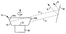
図8を参照すれば、多角体14の使用に関連する利点をはっきり理解することができる。
With reference to FIG. 8, the advantages associated with the use of the
内部ファセット24aからのレーザ・ビームは、セクションAおよびBを含む。個々のファセット24bが生成する光路長Liは、下式により表される。
Li=A+B
The laser beam from
L i = A + B
外部ファセット24bからのレーザ・ビームは、セクションCおよびDを含む。個々のファセット24bが生成する光路長Leは、下式により表される。
Le=C+D
The laser beam from
L e = C + D
結合光路長Lは、個々の光路長LiおよびLeの合計に等しい。すなわち、
L=A+B+C+D
Coupling the optical path length L is equal to the sum of the individual optical path lengths L i and L e. That is,
L = A + B + C + D
それ故、走査線の全長は、下式により表される。
S=(A+B+C+D)×φ
ここで、φは個々のファセット24aおよび24bが含むラジアンの数である。図の実施形態は、ウィンドウ上に個々のすべての走査線長さの合計である約240インチの走査線の全長を生成する。
Therefore, the total length of the scanning line is expressed by the following equation.
S = (A + B + C + D) × φ
Here, φ is the number of radians included in the
一方が内側のファセットであり、一方が外側のファセットである2つのファセットが同時に走査線を生成するので、二重表面多角体14も1つの反射面しか持たない多角体と比較すると、2倍の走査線を生成する。
Since two facets, one of which is the inner facet and one of which is the outer facet, simultaneously generate a scan line, the
また、角度有効範囲が増大する。内側のミラー・ファセット24aおよび外側のミラー・ファセット24bは、結合して増大した数の異なる入力ビーム角度から、より多くの出力ビーム角度を形成する。
Also, the effective angle range increases.
多角体14を使用することにより、コンパクトな光学的設計が容易になり、光路長を容易に延ばすことができ、走査範囲内の有効範囲を容易に広げることができる。
By using the
いくつかの好適な実施形態を特に参照しながら今まで本発明を説明してきたが、本発明の範囲から逸脱することなしに、本発明を種々に変更および修正することができる。 Although the invention has been described with particular reference to certain preferred embodiments, various changes and modifications can be made to the invention without departing from the scope of the invention.
Claims (7)
前記リングの内側に配置され、第1のレーザ・ビームを生成する第1のレーザと、A first laser disposed inside the ring and generating a first laser beam;
前記リングの内側に配置され、アイテムからの第1の反射光を集光する第1の集光装置と、A first light collecting device disposed inside the ring and collecting first reflected light from the item;
前記リングの外側に配置され、第2のレーザ・ビームを生成する第2のレーザと、A second laser disposed outside the ring and generating a second laser beam;
前記リングの外側に配置され、アイテムからの第2の反射光を集光する第2の集光装置と、A second light collecting device arranged outside the ring and collecting second reflected light from the item;
前記第1の集光装置と前記第2の集光装置からそれぞれ前記第1の反射光及び前記第2の反射光を受光して電気信号に変換する検出器と、A detector that receives the first reflected light and the second reflected light from the first light collecting device and the second light collecting device, respectively, and converts them into electrical signals;
前記第1のレーザ・ビームと前記第2のレーザ・ビームとから、走査パターンを形成させるためのパターン・ミラーと、を有し、A pattern mirror for forming a scanning pattern from the first laser beam and the second laser beam;
前記第1のミラー付きファセットは、前記第1のレーザ・ビームを前記パターン・ミラーに向けさせると共に前記第1の反射光を前記第1の集光装置に向けさせ、The first mirrored facet directs the first laser beam to the pattern mirror and directs the first reflected light to the first condensing device;
前記第2のミラー付きファセットは、前記第2のレーザ・ビームを前記パターン・ミラーに向けさせると共に前記第2の反射光を前記第1の集光装置に向けさせ、The second mirrored facet directs the second laser beam to the pattern mirror and directs the second reflected light to the first concentrator,
前記検出器は前記周辺壁面内の他方の側に配置された、ことを特徴とするバーコードスキャナ装置。The bar code scanner device characterized in that the detector is arranged on the other side in the peripheral wall surface.
前記第1のレーザ・ビームを反射する第1のパターン・ミラーと、A first pattern mirror that reflects the first laser beam;
前記第2のレーザ・ビームを反射する第2のパターン・ミラーと、A second pattern mirror that reflects the second laser beam;
を有する請求項1に記載のバーコードスキャナ装置。The barcode scanner device according to claim 1, comprising:
前記リングの外側に配置され、アイテムからの第3の反射光を集光する第3の集光装置と、A third concentrator disposed outside the ring and condensing third reflected light from the item;
をさらに備える、請求項1に記載のバーコードスキャナ装置。The barcode scanner apparatus according to claim 1, further comprising:
前記第1のレーザ・ビームを反射する第1のパターン・ミラーと、A first pattern mirror that reflects the first laser beam;
前記第2のレーザ・ビームを反射する第2のパターン・ミラーと、A second pattern mirror that reflects the second laser beam;
前記第3のレーザ・ビームを反射する第3のパターン・ミラーと、A third pattern mirror for reflecting the third laser beam;
を有する請求項6に記載のバーコードスキャナ装置。The bar code scanner device according to claim 6.
Applications Claiming Priority (1)
| Application Number | Priority Date | Filing Date | Title |
|---|---|---|---|
| US10/656,782 US7073716B2 (en) | 2003-09-05 | 2003-09-05 | Barcode scanner with dual-surface polygon |
Publications (3)
| Publication Number | Publication Date |
|---|---|
| JP2005085272A JP2005085272A (en) | 2005-03-31 |
| JP2005085272A5 JP2005085272A5 (en) | 2007-10-18 |
| JP4546192B2 true JP4546192B2 (en) | 2010-09-15 |
Family
ID=34136716
Family Applications (1)
| Application Number | Title | Priority Date | Filing Date |
|---|---|---|---|
| JP2004258437A Active JP4546192B2 (en) | 2003-09-05 | 2004-09-06 | Barcode scanner device with double surface polygons |
Country Status (4)
| Country | Link |
|---|---|
| US (1) | US7073716B2 (en) |
| EP (1) | EP1513096B1 (en) |
| JP (1) | JP4546192B2 (en) |
| DE (1) | DE602004025537D1 (en) |
Families Citing this family (4)
| Publication number | Priority date | Publication date | Assignee | Title |
|---|---|---|---|---|
| US8056810B2 (en) * | 2006-07-12 | 2011-11-15 | Ncr Corporation | Methods and apparatus for generating and decoding scan patterns using multiple laser sources |
| WO2010028371A1 (en) * | 2008-09-05 | 2010-03-11 | Zubiate, Brett | Multi-linked endoscopic device with spherical distal assembly |
| US8733651B2 (en) * | 2012-07-30 | 2014-05-27 | Ncr Corporation | Low profile tri-aperture optical code scanner |
| US9625709B1 (en) | 2015-09-29 | 2017-04-18 | Datalogic Usa, Inc. | Reduced windage prismatic polygonal reflector for scanning |
Citations (3)
| Publication number | Priority date | Publication date | Assignee | Title |
|---|---|---|---|---|
| JPH03191317A (en) * | 1989-12-20 | 1991-08-21 | Canon Inc | Scanning optical device |
| JPH03253811A (en) * | 1990-03-02 | 1991-11-12 | Fujitsu Ltd | Multidirectional reader |
| JPH07200714A (en) * | 1993-12-28 | 1995-08-04 | Nec Corp | Optical symbol reader |
Family Cites Families (10)
| Publication number | Priority date | Publication date | Assignee | Title |
|---|---|---|---|---|
| US3626091A (en) | 1969-12-11 | 1971-12-07 | Hughes Aircraft Co | Image converter |
| US3758187A (en) * | 1971-06-09 | 1973-09-11 | Kms Ind Inc | Method and apparatus for recording intelligence on a sheet material |
| US4795224A (en) | 1986-10-06 | 1989-01-03 | Katsuchika Goto | Optical scanning pattern generator |
| US5268565A (en) * | 1989-10-16 | 1993-12-07 | Fujitsu Limited | Compact type bar code reader |
| NL9401302A (en) * | 1994-08-11 | 1996-03-01 | Scantech Bv | Barcode scanner. |
| US5821520A (en) * | 1995-04-28 | 1998-10-13 | Symbol Technologies, Inc. | Bar code scanning system with the pre-decoding signal processing and method for bar code candidate selection for decoding |
| JPH09325290A (en) * | 1996-06-04 | 1997-12-16 | Matsushita Electric Ind Co Ltd | Scanning optical device |
| US5867298A (en) * | 1996-12-16 | 1999-02-02 | Eastman Kodak Company | Dual format pre-objective scanner |
| FR2761111B1 (en) | 1997-03-20 | 2000-04-07 | Schlumberger Services Petrol | METHOD AND APPARATUS FOR ACQUIRING DATA IN A HYDROCARBON WELL |
| US6292285B1 (en) * | 1999-12-20 | 2001-09-18 | Xerox Corporation | Single rotating polygon mirror with v-shaped facets for a multiple beam ROS |
-
2003
- 2003-09-05 US US10/656,782 patent/US7073716B2/en not_active Expired - Lifetime
-
2004
- 2004-09-01 DE DE602004025537T patent/DE602004025537D1/en active Active
- 2004-09-01 EP EP04020728A patent/EP1513096B1/en active Active
- 2004-09-06 JP JP2004258437A patent/JP4546192B2/en active Active
Patent Citations (3)
| Publication number | Priority date | Publication date | Assignee | Title |
|---|---|---|---|---|
| JPH03191317A (en) * | 1989-12-20 | 1991-08-21 | Canon Inc | Scanning optical device |
| JPH03253811A (en) * | 1990-03-02 | 1991-11-12 | Fujitsu Ltd | Multidirectional reader |
| JPH07200714A (en) * | 1993-12-28 | 1995-08-04 | Nec Corp | Optical symbol reader |
Also Published As
| Publication number | Publication date |
|---|---|
| EP1513096A3 (en) | 2006-01-25 |
| JP2005085272A (en) | 2005-03-31 |
| EP1513096B1 (en) | 2010-02-17 |
| EP1513096A2 (en) | 2005-03-09 |
| DE602004025537D1 (en) | 2010-04-01 |
| US20050051631A1 (en) | 2005-03-10 |
| US7073716B2 (en) | 2006-07-11 |
Similar Documents
| Publication | Publication Date | Title |
|---|---|---|
| US8408469B2 (en) | Laser scanning assembly having an improved scan angle-multiplication factor | |
| CA2170934C (en) | Optical scanners having dual surface optical elements for dual working ranges | |
| US5859417A (en) | Optical scanners having dual surface optical elements for dual working ranges | |
| JPS63218914A (en) | Laser light scanner | |
| JPH02301881A (en) | Bar code scanner | |
| EP0623889A1 (en) | Optical bar code scanner | |
| KR100444814B1 (en) | Optical scanning device and method and light source module | |
| JP4546192B2 (en) | Barcode scanner device with double surface polygons | |
| US5975418A (en) | Bar code scanner with increased number of scanning beams having different directions | |
| CN110622031A (en) | Lidar device and method with simplified detection | |
| US20090001168A1 (en) | Barcode scanner including a multi-tasking pattern mirror | |
| US6774366B1 (en) | Image integration and multiple laser source projection | |
| JP6036116B2 (en) | Laser radar equipment | |
| JP3866321B2 (en) | Optical scanner | |
| JP2001041823A (en) | Radiation detecting device | |
| JPH02101595A (en) | Bar-code scanner | |
| JPH11110474A (en) | Bar code reading device | |
| JP3497257B2 (en) | Optical scanning device | |
| JPH0690364B2 (en) | Laser light scanning / light receiving device | |
| JP2825108B2 (en) | Barcode information reader | |
| JP2761051B2 (en) | Information reading device | |
| JP2837664B2 (en) | Bar code reader | |
| JPH07168905A (en) | Bar code scanner | |
| JP2004020441A (en) | Apparatus for reading information on micro array | |
| JPH03129581A (en) | Bar code reader |
Legal Events
| Date | Code | Title | Description |
|---|---|---|---|
| A521 | Request for written amendment filed |
Free format text: JAPANESE INTERMEDIATE CODE: A523 Effective date: 20070904 |
|
| A621 | Written request for application examination |
Free format text: JAPANESE INTERMEDIATE CODE: A621 Effective date: 20070904 |
|
| A977 | Report on retrieval |
Free format text: JAPANESE INTERMEDIATE CODE: A971007 Effective date: 20090909 |
|
| A131 | Notification of reasons for refusal |
Free format text: JAPANESE INTERMEDIATE CODE: A131 Effective date: 20091005 |
|
| A521 | Request for written amendment filed |
Free format text: JAPANESE INTERMEDIATE CODE: A523 Effective date: 20100105 |
|
| TRDD | Decision of grant or rejection written | ||
| A01 | Written decision to grant a patent or to grant a registration (utility model) |
Free format text: JAPANESE INTERMEDIATE CODE: A01 Effective date: 20100618 |
|
| A01 | Written decision to grant a patent or to grant a registration (utility model) |
Free format text: JAPANESE INTERMEDIATE CODE: A01 |
|
| A61 | First payment of annual fees (during grant procedure) |
Free format text: JAPANESE INTERMEDIATE CODE: A61 Effective date: 20100701 |
|
| FPAY | Renewal fee payment (event date is renewal date of database) |
Free format text: PAYMENT UNTIL: 20130709 Year of fee payment: 3 |
|
| R150 | Certificate of patent or registration of utility model |
Ref document number: 4546192 Country of ref document: JP Free format text: JAPANESE INTERMEDIATE CODE: R150 Free format text: JAPANESE INTERMEDIATE CODE: R150 |
|
| R250 | Receipt of annual fees |
Free format text: JAPANESE INTERMEDIATE CODE: R250 |
|
| R250 | Receipt of annual fees |
Free format text: JAPANESE INTERMEDIATE CODE: R250 |
|
| R250 | Receipt of annual fees |
Free format text: JAPANESE INTERMEDIATE CODE: R250 |
|
| R250 | Receipt of annual fees |
Free format text: JAPANESE INTERMEDIATE CODE: R250 |
|
| R250 | Receipt of annual fees |
Free format text: JAPANESE INTERMEDIATE CODE: R250 |
|
| R250 | Receipt of annual fees |
Free format text: JAPANESE INTERMEDIATE CODE: R250 |
|
| R250 | Receipt of annual fees |
Free format text: JAPANESE INTERMEDIATE CODE: R250 |
|
| R250 | Receipt of annual fees |
Free format text: JAPANESE INTERMEDIATE CODE: R250 |
|
| R250 | Receipt of annual fees |
Free format text: JAPANESE INTERMEDIATE CODE: R250 |
|
| R250 | Receipt of annual fees |
Free format text: JAPANESE INTERMEDIATE CODE: R250 |
|
| R250 | Receipt of annual fees |
Free format text: JAPANESE INTERMEDIATE CODE: R250 |