JP4546018B2 - Fuel cells and electrical equipment - Google Patents
Fuel cells and electrical equipment Download PDFInfo
- Publication number
- JP4546018B2 JP4546018B2 JP2002187512A JP2002187512A JP4546018B2 JP 4546018 B2 JP4546018 B2 JP 4546018B2 JP 2002187512 A JP2002187512 A JP 2002187512A JP 2002187512 A JP2002187512 A JP 2002187512A JP 4546018 B2 JP4546018 B2 JP 4546018B2
- Authority
- JP
- Japan
- Prior art keywords
- fuel
- valve
- pressure
- electrode chamber
- fuel cell
- Prior art date
- Legal status (The legal status is an assumption and is not a legal conclusion. Google has not performed a legal analysis and makes no representation as to the accuracy of the status listed.)
- Expired - Fee Related
Links
Images


Classifications
-
- Y—GENERAL TAGGING OF NEW TECHNOLOGICAL DEVELOPMENTS; GENERAL TAGGING OF CROSS-SECTIONAL TECHNOLOGIES SPANNING OVER SEVERAL SECTIONS OF THE IPC; TECHNICAL SUBJECTS COVERED BY FORMER USPC CROSS-REFERENCE ART COLLECTIONS [XRACs] AND DIGESTS
- Y02—TECHNOLOGIES OR APPLICATIONS FOR MITIGATION OR ADAPTATION AGAINST CLIMATE CHANGE
- Y02E—REDUCTION OF GREENHOUSE GAS [GHG] EMISSIONS, RELATED TO ENERGY GENERATION, TRANSMISSION OR DISTRIBUTION
- Y02E60/00—Enabling technologies; Technologies with a potential or indirect contribution to GHG emissions mitigation
- Y02E60/30—Hydrogen technology
- Y02E60/50—Fuel cells
Description
【0001】
【発明の属する技術分野】
本発明は、燃料電池に関し、特に小型の燃料電池における圧力制御弁に関するものであり、デジタルカメラ、デジタルビデオカメラ、小型プロジェクタ、小型プリンタ、ノート型パソコンなどの持ち運び可能な小型電気機器に搭載可能な発電量が数ミリワットから数百ワットまでの固体高分子型燃料電池に有効である。
【0002】
【従来の技術】
従来、小型の電気機器を持ち運んで使用するためには、種々の一次電池、二次電池が使用されてきた。しかし、最近の小型電気機器の高性能化に伴い、消費電力が大きくなり、一次電池では、小型軽量で、十分なエネルギーを供給できなくなっている。一方、二次電池においては、繰り返し充電して使用できるという利点はあるものの、一回の充電で使用できるエネルギーは一次電池よりも更に少ない。今後、電気機器のますますの小型、軽量化が進み、ワイヤレスのネットワーク環境が整うことにより、機器を持ち運んで使用する傾向が高まる中で、従来の一次電池、二次電池では機器の駆動に十分なエネルギーを供給することは困難である。
【0003】
このような問題の解決策として、小型の燃料電池が注目されている。燃料電池は従来、大型の発電機、自動車用の駆動源として開発が進められてきた。これは燃料電池が、従来の発電システムに比べて、発電効率が高く、しかも廃棄物がクリーンであることが主な理由である。一方、燃料電池が小型電気機器の駆動源として有用な理由に体積当たり、重量当たりの供給可能なエネルギー量が従来の電池に比べて、数倍から十倍近くであることが挙げられる。
【0004】
燃料電池には、様々な方式のものが発明されているが、小型電気機器、とりわけ持ち運びして使用する機器に対しては、固体高分子型燃料電池が適している。
これは、常温に近い温度で使用でき、また、電解質が液体ではなく固体であるので、安全に持ち運べるという利点を有しているためである。
【0005】
小型電気機器用の燃料電池の燃料としては、従来メタノールが検討されてきた。これは、出力は小さいものの、メタノールが保存しやすく、また入手しやすい燃料であることが主な理由であった。
【0006】
大きな出力を得るための燃料電池には、水素を燃料に使用するのが最適である。しかし、水素は常温で気体であり、小型の燃料タンクの中に高密度に水素を貯蔵するための技術が必要である。第一の方法は水素を圧縮して高圧ガスとして保存する方法であるが、ガスの圧力を200気圧まで高めても体積水素密度は18mg/cm3 程度である。その上、高圧のガスタンクを安全に扱うためには、タンクの肉厚を大きくする必要があり、小型化には向かない。
【0007】
第二の方法は水素を低温にして、液体として貯蔵する方法である。この方法では、高密度な保存が可能であるが、水素を液化するためには、大きなエネルギーが必要であること、また、液体水素が自然気化して、漏れだしてしまうことが問題である。
【0008】
第三の方法は水素吸蔵合金を使用して水素を貯蔵する方法である。この方法では、水素吸蔵合金の比重が大きいため、重量ベースでは、2wt%程度の水素しか吸蔵できず、燃料タンクが重たくなってしまうという問題点があるが、体積ベースでの吸蔵量は大きいので、小型化には有効である。
【0009】
第四の方法では、メタノールやガソリンなどを燃料タンクに積み、改質して水素に変換し使用するという方法があるが、改質反応は100℃以上の高温であること、改質器が必要となることから、小型電気機器用には向かない。これらの方式に比べ、燃料を高密度に貯蔵するために、カーボンナノチューブ、グラファイトナノファイバー、カーボンナノホーンなどの炭素系材料が注目されている。これらの炭素系材料では、重量当たり約10wt%の水素が吸蔵可能であるといわれている。
【0010】
また、同様に高密度に水素を吸蔵する方法として、ケミカルハイドライドを用いるものがある。ケミカルハイドライドは化学反応を利用して、水素を吸蔵、放出する化合物で、大きく分けて有機系と無機系の材料がある。無機系のケミカルハイドライドとしては、ボロハイドライドがある。また、有機系のケミカルハイドライドとしては、シクロヘキサンやデカリンなどがある。これらの化合物は5〜10wt%程度の水素を吸蔵可能である。
【0011】
これにより、例えばデジタルカメラ用の電源として使用する場合、従来のリチウムイオン電池を用いた場合に比べ、3〜5倍程度の撮影が可能である。
ただし、炭素系材料やケミカルハイドライドを用いた水素貯蔵方式は重量当たりの水素吸蔵能力は高いが、吸蔵材料自体の密度が小さいため、小型の燃料タンクには、水素吸蔵合金が適している。
【0012】
一方、固体高分子型燃料電池の発電は以下の様にして行われる。高分子電解質膜には、パーフルオロスルホン酸系の陽イオン交換樹脂がよく用いられる。例えば、このような膜としては、デュポン社のナフィヨンなどがよく知られている。
固体高分子電解質膜を、白金などの触媒を担持した一対の多孔質電極、すなわち、燃料極と酸化剤極とで狭持した膜電極複合体が発電セルとなる。この発電セルに対して、酸化剤極には酸化剤を、燃料極には燃料を供給することにより、高分子電解質膜中をプロトンが移動し、発電が行われる。
【0013】
高分子電解質膜は機械的強度を保ち、また、燃料ガスが透過しないようにするために通常50〜100μm程度の厚さのものが使用される。これらの固体高分子電解質膜の強度は0.3〜0.5MPa程度である。従って、差圧による膜の破断を防ぐためには、燃料電池の酸化剤極室と燃料極室との差圧が、平常時には0.05MPa、非常時でも0.1MPa以下になるように制御することが好ましい。
【0014】
燃料タンク圧と酸化剤極室との差圧が上記圧力よりも小さい場合、燃料タンクと燃料極室とを直結し、特に減圧の必要はないが、酸化剤極室が大気に解放されており、また、より高密度に燃料を充填する場合においては、燃料タンクから燃料極室に燃料を供給する過程において、減圧する事が必要となる。また、発電の起動・停止操作や、発電電力を安定させるためにも、上記機構は必要となる。
通常、発電所、家庭用発電システム、車載用燃料電池など大型の燃料電池システムにおいては、燃料極室、および酸化剤極室に圧力センサを設け、これらの信号を元に、燃料供給路の圧力バルブの制御を行っていた。
【0015】
しかし、小型化の燃料電池システムにこれらのセンサおよび配線類を具備させることはシステムの大型化、複雑化の原因となっていた。そこで、これらのセンサを排除し、小型の燃料流量制御機構を実現しようとした試みもある。特開2002−33112においては、プロトン導電体の積層体を、該積層体とバルブが連動して移動可能な様にし、プロトン導電体膜が燃料極室と酸化剤極室の差圧によってたわむことを利用して、弁の駆動を行っている。また、同発明の別の実施例においては、バルブにヒーターコイルが巻回され、バイメタルによって構成された開閉部材が、燃料電池の発電量に応じてヒーターコイルに電流が流れることによって変形することを利用して、燃料流量を制御しようとしている。
【0016】
【発明が解決しようとする課題】
しかしながら、従来燃料電池に使用されるバルブは大型であり、持ち運んで使用可能な小型電気機器に搭載可能な小型の燃料電池システムを実現することは困難であった。また、バルブの他にも制御信号を送る圧力センサが必要であり、システムの小型化、簡素化を妨げていた。
【0017】
さらには、燃料電池は発電機関であるにも関わらず、バルブやセンサを駆動するためや信号を伝達するために電力が必要であり、外に取り出し可能な発電量を低下させていた。
【0018】
また、差圧によるダイヤフラム駆動型の小型減圧弁に関しては、設定圧付近での微小な圧力変化に起因する弁の振動が発生したり、また、弁での流量を発電により消費される燃料の量と等しくなるように調節する機能を有していないため、頻繁にバルブをON/OFFする必要があり、バルブの寿命を著しく損なうばかりか、安定した発電を困難にしていた。
【0019】
また、燃料電池セルを減圧弁のダイヤフラムとして使用する発明(特開2002−33112)においては、燃料電池セルが振動するため燃料電池セルにダメージを与えてしまう、大きな力が働いた場合に膜が破断する、燃料電池セルを支える構造部材がないためタンクの圧力に耐えられない、燃料電池セル自体が3層構造になっているため、バルブの開閉に伴って接合部から燃料がリーク(漏れ)する、燃料電池セルの一部が弁の支持部として使用されるため発電効率が低下する、工程が複雑でコストが高くなる、複数のセルを積層して用いる場合には適用できない、といった問題を有していた。
【0020】
本発明は、この様な従来技術に鑑みてなされたものであり、小型燃料電池に搭載可能な、非常に小型に製作したバルブである小型減圧弁を使用し、減圧弁の微小な圧力変化による振動を抑制し、発電電力を安定して供給することが可能な燃料電池を提供することを目的とするものである。
【0021】
また、本発明は、燃料タンクからの圧力を最適に減圧して燃料電池セルに供給することができ、燃料電池セルを大きな差圧による破断から防ぎ、発電の起動、停止および安定した電力が提供できる燃料電池を提供することを目的とするものである。
【0022】
【課題を解決するための手段】
即ち、本発明は、酸化剤極室と、燃料極室と、前記燃料極室に供給する燃料を収納している燃料タンクと、前記燃料極室と前記燃料タンクを連結する燃料流路とを有し、前記燃料流路に、前記燃料タンクの圧力と前記燃料極室の圧力との差圧と、前記燃料極室の圧力と前記酸化剤極室または外気の圧力との差圧を利用して、前記燃料タンクから前記燃料極室への燃料の供給量を制御する制御機構を備えた燃料電池であって、前記燃料の供給量を制御する制御機構が、前記燃料極室の圧力と前記酸化剤極室または外気の圧力との差圧を検出するためのダイヤフラムあるいはベローズからなる差圧検出機構、燃料流量を制御するための絞り機構を有するバルブおよび前記差圧検出機構と前記バルブとを連結するための前記バルブの軸からなる連結機構からなることを特徴とする燃料電池である。
【0023】
前記酸化剤極室が外気に解放されていることが好ましい。
前記燃料極室の圧力と酸化剤極室または外気の圧力の差圧を検出する差圧検出機構がダイヤフラムまたはベローズであり、該ダイヤフラムまたはベローズの片面が燃料極室に、もう一方の面が酸化剤極室または外気に接していることが好ましい。
【0024】
前記ダイヤフラムまたはベローズがステンレス、ベリリウム、ハステロイ、カンタル、真鍮、アルミニウム、リン青銅から選ばれる金属、シリコーンゴム、フッ素ゴム、NBR、EPT、ウレタンゴムから選ばれる非金属材料、シリコンからなる半導体材料のいずれかの材料よりなることが好ましい。
前記ダイヤフラムの表面が波形形状を有することが好ましい。
前記燃料極室の圧力が燃料極室の圧力に対し、過剰になった場合に燃料極室の圧力と酸化剤極室または外気の圧力の差圧を検出する差圧検出機構を保護するストッパー機構を有することが好ましい。
【0025】
前記ストッパー機構が燃料極室の圧力と酸化剤極室または外気の圧力の差圧を検出する差圧検出機構の酸化剤極室または外気と接している側に配置されていることが好ましい。
前記ストッパー機構が多孔質体かまたは通気穴を有する構造であることが好ましい。
外気の圧力が燃料極室の圧力に対し、過剰になった場合に燃料極室の圧力と酸化剤極室または外気の圧力の差圧を検出する差圧検出機構を保護するストッパー機構を有することが好ましい。
【0026】
前記ストッパー機構が燃料極室の圧力と酸化剤極室または外気の圧力の差圧を検出する差圧検出機構の燃料流路と接している側に配置されていることが好ましい。
前記ストッパー機構が燃料流路の内壁であることが好ましい。
前記ストッパー機構が燃料流量を制御するバルブと接することにより作動することが好ましい。
【0027】
燃料極室の圧力と酸化剤極室または外気の圧力の差圧を検出する差圧検出機構と、燃料タンクからの燃料の流量を制御するバルブとを連結する連結機構が軸からなり、差圧検出機構の変位によって弁体が駆動することが好ましい。
燃料極室の圧力と酸化剤極室または外気の圧力の差圧を検出する差圧検出機構と、燃料タンクからの燃料流量を制御するためのバルブとを連結する連結機構の軸の長さによって、バルブが開く圧力を調節することが好ましい。
燃料流量を制御するためのバルブの軸と軸穴との摩擦を低減する機構を有することが好ましい。
【0028】
前記バルブの軸と軸穴との摩擦を低減する機構は、軸及び軸穴の少なくとも一方の表面に摩擦を低減する性質を持つ材料をコーティングしてなることが好ましい。
前記バルブの軸と軸穴との摩擦を低減する機構は、軸と軸穴の間を通る燃料の流れを利用した気体軸受けであることが好ましい。
燃料流量を制御するためのバルブを有する流路に絞り機構を有することが好ましい。
【0029】
バルブの燃料の流量を制御するための絞り機構が、オリフィス構造となっていることが好ましい。
前記オリフィス構造を持つバルブの弁体が実質的に球形をしていることが好ましい。
前記バルブの燃料の流量を制御するための絞り機構がチョーク構造となっていることが好ましい。
【0030】
前記チョーク構造として、バルブの軸に対して平行な溝を1つ以上有することが好ましい。
前記チョーク構造として、バルブの軸に対して垂直に凸凹溝を有することが好ましい。
前記チョーク構造として、バルブの軸にスクリュー状の溝を有することが好ましい。
前記チョーク構造として、バルブの軸に多孔質材料からなる部分を有することが好ましい。
【0031】
燃料極室の圧力と酸化剤極室または外気の圧力との差圧および燃料タンクの圧力に応じて、燃料タンクからの燃料の流量を制御するバルブの開度が変化することで、燃料の流量を制御し、燃料の供給量が燃料の消費量に等しくなるように制御される制御機構を備えることが好ましい。
前記バルブがチョーク構造を有し、該バルブの開度によって流量が変化する機構として、弁体および軸穴がテーパー状となっているこことが好ましい。
前記バルブがチョーク構造を有し、該バルブの開度によって流量が変化する機構として、バルブ軸がテーパー状となっていることが好ましい。
【0032】
前記バルブがチョーク構造を有し、該バルブの開度によって流量が変化する機構として、テーパー状の溝を1つ以上有することが好ましい。
前記バルブがチョーク構造を有し、該バルブの開度によって流量が変化する機構として、バルブの径が途中で変化する段差を有することが好ましい。
前記バルブがチョーク構造を有し、該バルブの開度によって流量が変化する機構として、上記の絞り構造の機構を複数組み合わせてなることが好ましい。
【0033】
バルブが燃料の流路をふさぐ部分において、バルブまたは流路の少なくとも一方の表面がシリコーンゴム、フッ素ゴム、NBR、EPT、ウレタンゴムから選ばれる燃料のリーク(漏れ)を軽減する性質を持つ材料からなることが好ましい。
軸穴の弁体が接する部分にテーパーを有することが好ましい。
燃料極室に燃料を一時的に蓄えておく燃料バッファを有することが好ましい。
燃料タンクとバルブとの間にバルブの目詰まりを防止するためのフィルタを有することが好ましい。
燃料タンクとバルブとの間に燃料圧力を減圧するための減圧機構を有することが好ましい。
【0034】
前記減圧機構が燃料抵抗膜からなることが好ましい。
前記減圧機構が絞り形状からなることが好ましい。
燃料タンクにリリーフ弁を有することが好ましい。
燃料極室の過剰な燃料を減らす機構を有することが好ましい。
燃料極室の過剰な燃料を減らす機構としてリリーフ弁を有することが好ましい。
燃料極室の過剰な燃料を減らす機構として、燃料電池の発電を行うことが好ましい。
【0035】
燃料タンクからの燃料の流量を制御するバルブの開閉がヒステリシスを持つことが好ましい。
燃料タンクからの燃料の流量を制御するバルブの開閉がヒステリシスを持つための機構として、バルブの弁体に隣接した燃料タンク側に電磁石または永久磁石を有し、バルブの弁体が鉄、ニッケル、コバルトから選ばれる磁性体または永久磁石からなることが好ましい。
【0036】
燃料タンクからの燃料の流量を制御するバルブの開閉がヒステリシスを持つための機構として、バルブの弁体に隣接した燃料タンク側または弁体の一方にエレクトレット材料を有し、またもう一方にエレクトレット材料または誘電体からなることが好ましい。
【0037】
また、本発明は、上記の燃料電池を使用した電気機器である。
【0038】
【発明の実施の形態】
本発明の燃料電池は、燃料極室の圧力と酸化剤極室または外気の圧力の差圧を利用して、燃料タンクからの燃料の供給量を制御する制御機構を備えることを特徴とする。
【0039】
本発明では、上記の構成により、小型バルブを燃料タンクと燃料電池セルの間に設けることにより、燃料電池セルを大きな圧力差による破断から防ぎ、発電の起動、停止を制御し、発電電力を安定に保つことができる。
【0040】
特に、本発明では、燃料供給路と酸化剤供給路との境界にダイヤフラムを使用し、バルブに直結することで、電気を使用しないで、燃料供給路と酸化剤供給路との差圧により駆動し、燃料電池セルに供給する燃料圧を最適に制御する減圧弁を実現する。
【0041】
また、本発明は、燃料タンク圧、発電に伴う燃料の消費量にあわせて、弁での流路抵抗を最適に変化させ、燃料の流量を制御することにより、弁の駆動を最低限にすることができる。
また、本発明は、燃膜の大きさ、厚さ、材質、流路幅、バルブサイズなどを最適に設計することができ、微小な圧力差に起因する弁の振動を抑制することができる。
【0042】
【実施例】
本発明のマイクロバルブを搭載した燃料電池について説明する。
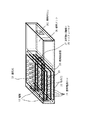
図1は本発明の燃料電池の概観を表す斜視図である。図2は本発明の燃料電池のシステムの概要図である。図3は本発明の燃料電池の平面図、および図4は本発明の燃料電池の正面図である。燃料電池の外寸法は50mm×30mm×10mmであり、通常コンパクトデジタルカメラで使用されているリチウムイオン電池の大きさとほぼ同じである。
【0043】
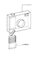
図20は本発明の燃料電池50をデジタルカメラ51に搭載した場合の概要図である。このように本発明のデジタルカメラは小型で一体化されているため、携帯機器に組み込みやすい形状となっている。
【0044】
本発明の燃料電池は、酸化剤として反応に用いる酸素を外気から取り入れるため、上下面、及び側面に外気を取り入れるための通気孔13を有する。また、この通気孔13は生成した水を水蒸気として逃がしたり、反応により発生した熱を外に逃がす働きもしている。また、一方の側面には、電気を取り出すための電極12がある。内部は、高分子電解質膜112、セル電極の酸化剤極111、燃料極113、触媒からなる燃料電池セル11と、燃料を貯蔵する燃料タンク16、燃料タンクと各セルの燃料極とをつなぎ、燃料の流量を制御する燃料供給部15によって構成されている。燃料供給部15は燃料極に燃料を供給する燃料極室27と酸化剤極に酸化剤を供給する酸化剤極室28の圧力差を測定する差圧検出機構17、燃料流路で燃料の供給を制御するマイクロバルブ18によって構成されている。また、発電に伴い生成する水が多い場合には、生成した水を蓄えておく保水部14を有する場合もある。
【0045】
本発明の燃料電池セルは起電力0.8V、電流密度300mA/cm2 であり、単位セルの大きさは1.2cm×2cmである。この燃料電池セルを8枚直列につなぐことで、電池全体の出力は6.4V、720mAで4.6Wである。
【0046】
燃料タンク16について説明する。タンクの内部には水素を吸蔵することが可能な水素吸蔵合金が充填されている。燃料電池に用いる高分子電解質膜の耐圧が0.3〜0.5MPaであることから、外気との差圧が0.1MPa以内の範囲で用いる必要がある。
【0047】
水素吸蔵合金として、例えばLaNi5 などを用いると、水素の解放圧は常温で0.2MPa程度である。燃料タンクの容積を燃料電池全体の半分とし、タンク肉厚を1mm、タンク材質をチタンとすると、この時、燃料タンクの重量は50g程度となり、また、燃料タンク体積は5.2cm3 になる。LaNi5 は重量当たり1.1wt%の水素を吸脱着可能なので、燃料タンクに蓄えられている水素量は0.4gであり、発電可能なエネルギーは、約11.3[W・hr]であり、従来のリチウムイオン電池の約4倍である。また、燃料タンクには温度変化などにより、燃料圧が増加しすぎることを防ぐために、リリーフバルブを設けることも可能である。
【0048】
一方、水素の解放圧が常温で0.2MPaを超えるような水素吸蔵材料を用いる場合には、燃料タンクと燃料極との間に減圧のためのマイクロバルブ18を設ける必要がある。
【0049】
タンクに蓄えられた水素は燃料供給部15を通って、燃料極113に供給される。また酸化剤極111には通気孔13から外気が供給される。燃料電池セルで発電された電気は電極12から小型電気機器に供給される。
【0050】
図5は本発明に用いられるバルブの一例として減圧弁を示す断面図である。減圧バルブはダイヤフラム23、弁体21、弁体とダイヤフラムを直結するバルブ軸22、バルブ軸が通り、燃料が通過する軸穴24からなっている。ダイヤフラムの代わりにベローズを使用しても良い。ダイヤフラムは片面を燃料極室27と接し、もう片面を酸化剤極室(外気)と接している。弁体21は燃料タンク16から燃料極室27までの燃料流路30をふさぐ形で取り付けられている。バルブ全体のサイズは1cm角以内であり、弁体の大きさは1mm角以内となっている。このように小さなバルブ機構を実現することにより、小型燃料電池に燃料流量の制御機構を組み込むことが可能になっている。
【0051】
弁体と流路の接する部分にはリーク(漏れ)を抑えるために、シール部材25をコーティングする。シール部材には、シリコーンゴムなどの弾性体が有効である。シール部材は流路か弁体の片方につけても、両方につけても良い。
【0052】
以下に燃料電池の発電に伴うバルブの開閉動作を説明する。発電停止中図6(b)に示す通りバルブは閉じている。発電が始まると燃料極室の燃料は消費され、燃料極室の燃料の圧力は下がっていく。ダイヤフラムは、外気圧と燃料極室の圧力との差圧から、燃料極室側にたわむ(図の下方向)。これにより、ダイヤフラムにバルブ軸で直結されたバルブは押し下げられ、バルブは開く(図6(a))。これにより、燃料タンクから、燃料極室に燃料が供給される。燃料極室の圧力が回復すると、ダイヤフラムは上に押し上げられ、それとともにバルブも閉じる。
【0053】
バルブは燃料極室の圧力が外圧よりも低くならない限り開かないため、燃料極室が破損して燃料が漏れたり、バルブが壊れた場合においてもバルブは閉じた状態になり、タンクからの燃料漏れを防ぐことができる。
【0054】
差圧検知部分には、ダイヤフラムまたはベローズを用いることができる。ベローズ31は図7(c)に示す構造で、小さな圧力差で大きな変位が得られるという特徴がある。ベローズの材料には、ステンレス、リン青銅、ベリリウムなどがある。
【0055】
一方、ダイヤフラム23は、構造が単純で製作しやすい。ダイヤフラムは材料・構造によって非金属ダイヤフラム図7(a)と金属ダイヤフラム図7(b)に大きく分かれる。非金属材料ダイヤフラムはゴムなどの弾性体材料を用いるもので、構造が非常に単純であるが、強度や支持部材との接合部でのリーク(漏れ)しにくさという点では金属ダイヤフラムの方が優れている。また、バルブ軸との接合部での強度も金属ダイヤフラムが優れている。金属ダイヤフラムは、より大きな変位を得るために、波形に成形される場合が多い。非金属料ダイヤフラムの材料には、シリコーンゴム、フッ素ゴム、NBR、EPT、ウレタンゴムなどがある。金属ダイヤフラムの材料にはステンレス、ベリリウム、ハステロイ、カンタル、真鍮などがある。
【0056】
ダイヤフラムは、半径を1[mm]とすると、材料がシリコーンゴムの場合には厚さが0.6[μm]程度、アルミの場合には厚さが0.06[μm]以上であれば、十分な強度を有する。これらの材料は以下に述べる設計指針や形状、製造方法により、適宜選択することができる。
【0057】
差圧検知機構の特性を、シリコーンゴム製のダイヤフラムを用いた場合を例に述べる。半径r、厚さhの周辺固定円盤に均等圧力がかかる場合の中心部の変位ωは次式で表される。
【0058】
【数1】
ただし、
【0060】
【数2】
【0061】
ここで、Eはヤング率、mはポアッソン比(-1)、Pは圧力である。ダイヤフラム半径を1[mm]、厚さを0.1[mm]とすると、シリコーンゴムのヤング率4.95[MPa]、m-1=0.45より、ダイヤフラムに差圧が0.01MPa(約0.1[atm])かかった場合の中心部のたわみは、0.3[mm]程度となる。従って、ダイヤフラムのばね定数k=P×πr2 /ω=103.9[N/m]となる。
【0062】
また、シリコーンゴムの密度は1.2[g/cm3 ]程度であることから、ダイヤフラム質量は0.38[mg]となる。従って、ダイヤフラムの固有振動数fは16.6[kHz]程度となる。
【0063】
軸の長さを調節することにより、バルブが開く時の燃料極室の圧力P20を変えることができる。差圧検出機構からバルブまでの距離と軸の長さとの差をx0 とすると、バルブは燃料極室の圧力が、
【0064】
【数3】
【0065】
バルブ軸と軸穴との摩擦を低減するために、軸及び軸穴の表面にテフロン(登録商標)など摩擦を低減する性質を持つ材料でコーティングしたり、軸と軸穴の間を通る燃料の流れを利用して気体軸受けとして用いることも可能である。気体軸受けについては、通常のバルブ、軸穴、軸の構成であっても、効果は期待できるが、図8(a)〜図8(c)のような構造を用いれば更に軸受けの効果が高まる。
【0066】
また、燃料極室の圧力が過剰に上がってしまった場合に、ダイヤフラムおよびバルブの破損を防ぐために、ダイヤフラムの酸化剤極室側にストッパー機構26を備えることも可能である。ストッパー機構によって、ダイヤフラムに酸化剤極室(外気)の圧力が伝わらなくなることと防ぐために、ストッパー機構は多孔質材料からなるか通気口を有する。また、該ストッパー機構は燃料電池の発電セル同士が接することを防ぐ支持部材と兼ねることも可能である。
【0067】
一方、酸化剤極室の圧力が燃料極室の圧力に対して過剰である場合にも、ストッパー機構を設けることが可能である。ストッパー機構26は図19(a)に示すように、ダイヤフラム23の燃料極室側にダイヤフラムの動きを止めるように設置することができる。また、図19(b)に示すように燃料流路壁を利用することも可能である。また、図19(c)に示すように、マイクロバルブ18の動きを止めるように設置することも可能である。
【0068】
材料の強度について以下に述べる。燃料タンクはタンク内圧力が0.5MPa(約5気圧)とし、安全率を5として計算すると、材料がステンレスの場合は1mm程度、チタンの場合は0.8mm程度まで薄くすることが可能である。バルブの軸穴を有する板部材に関しては0.5mm程度の厚さで十分である。さらに、穴板に補強部材29をつければ、穴板自体の厚さはステンレスを用いた場合で、0.2[mm]まで薄くすることが可能である。
【0069】
燃料電池での水素消費量は以下の通りである。燃料極での反応がH2 →2H+ +2e- である。従って、1[A]の電流を流した場合の水素消費量は、5.1×10⁻⁶ [mol/s]、すなわち標準状態で、114[mm3 /s]である。一方、タンクにLaNi5 を充填し、容積が5.15[cm3 ]の場合の各温度における水素放出速度は下記の表1に示す通りである。従って、本燃料電池においては、水素消費量に比べて十分速くタンクから水素を供給できる。
【0070】
【表1】
本実施例では、燃料電池セル間の燃料極室体積は、燃料電池全体が非常に小さくかつ薄いため、750[mm3 ]程度であり、発電に伴う水素流量に比べて小さい。そこで、燃料電池のセルに、燃料極室には燃料流量の急激な変化を和らげるためのバッファー機構をもうけることもできる。例えば発電セルと燃料タンクとの間にバッファーとして、8×28×3.6[mm]の領域を設けると、バッファー領域の体積は805[mm3 ]となり、燃料極室全体の体積を2倍にまで広げることができる。
【0072】
また、燃料極室で燃料圧が急激に増加した場合に、圧力を下げるための機構を設けることが可能である。減圧には、リリーフバルブを設ける方法や、余分に発電を行い、燃料を消費する方法が有効である。
【0073】
LaNi5 の温度による解離圧の変化を下記の表2に示す。この表2から、本発明の燃料電池をデジタルカメラなどの小型電気機器に搭載して用いる場合、燃料タンクの圧力は0.1〜0.4MPa程度である。
【0074】
【表2】
図9に示すように、外気の圧力をP0 、燃料タンクの圧力をP1 、燃料極室の圧力をP2 とし、バルブの底面の面積をS1 、ダイヤフラム面積をS2 とすると、圧力の釣り合いから、バルブが開く条件は、P0を0.1MPa(約1[atm])、(P1 −P2 )S1 <(P0 −P2 )S2 となる。従って、S1 およびS2 を決定することにより、バルブが開くときの燃料極室の圧力P20を最適に設計することができる。例えば、S1 :S2 =1:16にしたときの、様々なP1 でのP20を表にすると、下記の表3に示すようになる。この場合、P1 が0.4MPa(約4[atm])以下程度であれば、バルブは適切に動作し、一方、過剰な加熱などにより、P1 が著しく高くなった場合には、バルブが開かなくなり、発電が停止するので、バルブが安全装置として働く。
【0076】
【表3】
バルブの形状には様々なものが考えられる。例えば、バルブの絞り形状を図10のようにオリフィスにすることも可能である。燃料を比圧縮流体と仮定した場合、バルブの通過流量QとP1 とP2 の差圧ΔPとの関係は次式で表される。
【0078】
【数4】
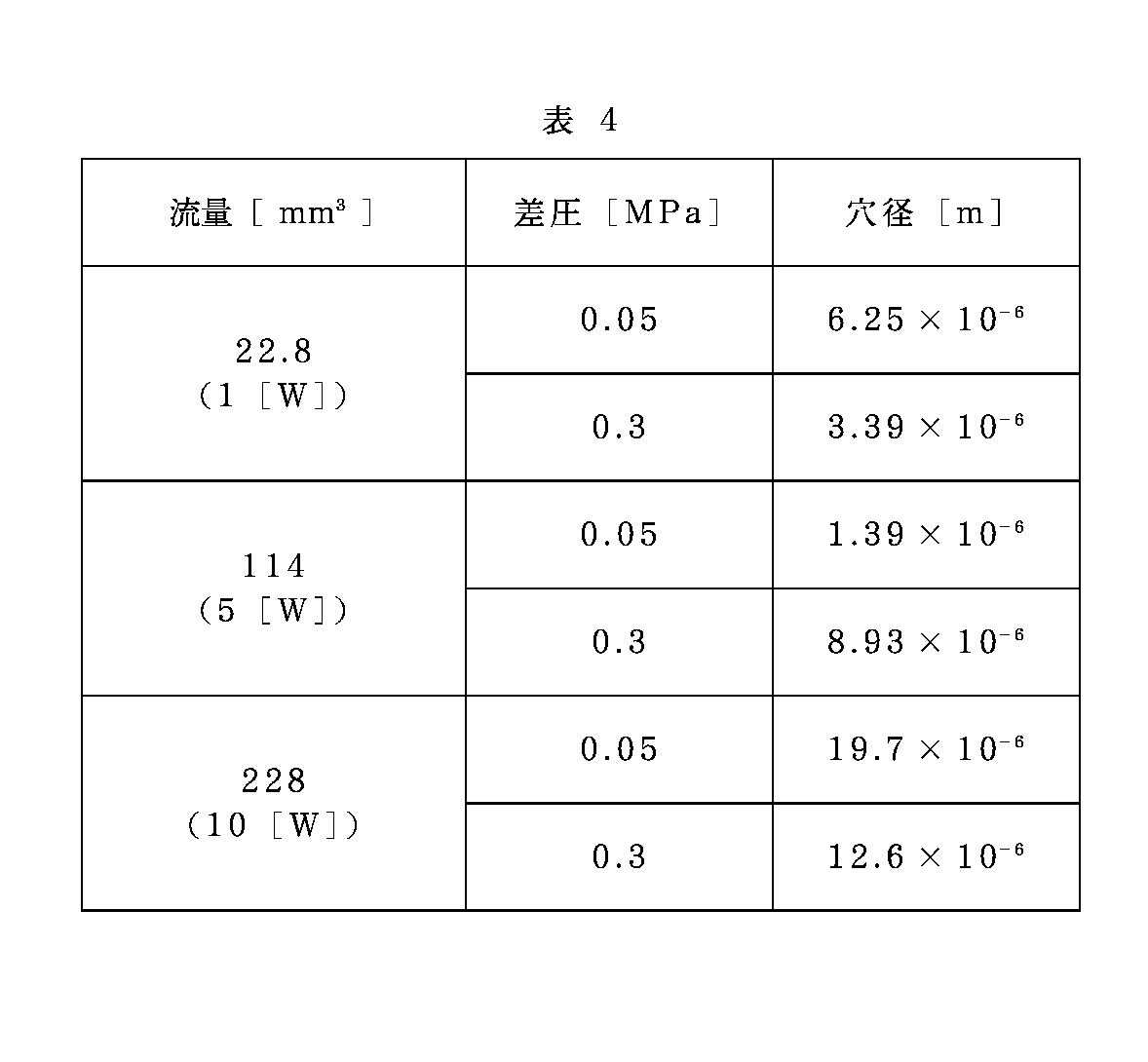
ただし、Aは絞り面積、Cd は流量係数、ρは流体の密度である。Cd =0.7、ρ=0.0899[kg/m3 ](水素標準状態)としたときのAとQとΔPの関係を示したのが下記の表4である。十分な発電を行うための流量を得るためには、オリフィス径は10[μm]程度であることが分かる。
【0080】
【表4】
また、オリフィスの形状の一つとして、バルブ形状を図11に示すように、球形にすることも可能である。
さらに大きな減圧効果を得るために、バルブの絞り形状を図12に示すようにチョーク絞りにすることも可能である。この場合、バルブでの流量と圧力との関係は以下のように表される。
【0082】
【数5】
ここで、μは粘性係数、ΔPは絞り前後の圧力差、Dは絞り穴径、Lは絞り部の長さである。μ=8.8×10⁻⁶[Pa/s]、L=0.5[mm]とすると、様々な穴径での流量と絞り部での差圧(P1 とP2 の圧力差)は下記の表5に示すようになる。従って、適当な穴径は25〜75μm程度となる。
【0084】
【表5】
チョーク絞りの形状32は、必要な絞りの抵抗に合わせて、軸に対して平行な溝33を1つ以上設ける方法(図13(a))や、軸穴の中心にバルブ軸が通り、その隙間34を流路として用いる方法(図13(b))、軸に対して垂直に凸凹溝35を設ける方法(図13(c))や、軸にスクリュー状の溝36を設ける方法(図13(d))や、軸に多孔質材料37からなる部分を設ける方法(図13(e))を用いることも可能である。例えば、図13(a)の場合、穴径dの小流路がn個あるとすると、流量と差圧との関係は以下のように表される。
【0086】
【数6】
また、図13(b)の場合、円形流路の幅をh、半径をrとすると流量と差圧との関係は以下のように表される。
【0088】
【数7】
しかしながら、これらのバルブ機構だけでは、絞り部での抵抗が変化しないため、燃料の流量を段階的に制御することが難しく、燃料の流量が多すぎて、頻繁にバルブを閉じなければならなかったり、十分な流量を得ることが難しかったりという問題が生じる。そこで、本発明のバルブは、燃料極室の圧力と酸化剤極室または外気の圧力の差圧および燃料タンクの圧力に応じて、燃料タンクからの燃料の流量を制御するバルブの開度が変化することで、燃料の流量を制御し、燃料の供給量が燃料の消費量に等しくなるように制御される。本機能が実現される仕組みを以下に詳細に説明する。
【0090】
本発明のバルブはバルブが開くに従って、バルブ部分での流路抵抗が小さくなるようになっている。これは通常のオリフィス、チョーク弁でも弁体の抵抗により有る程度は実現は可能であるが、例えば、図14(a)に示すように、弁体21およびバルブ軸穴24がテーパーを有して接している方法を用いればより効果的である。この場合、バルブが開くに従って、流路幅が広くなるので、流量が増加する。その他にバルブが開くに従って、バルブ部分での流路抵抗が小さくなるような機構としては、図14(b)のように、バルブ軸径がテーパー状に変化するする方法がある。この場合、テーパー構造を有する溝を複数設けてもよい。また、図14(c)のように、バルブの径が途中で変化する段差を設ける方法もある。また、図14(d)のようにバルブの一部にのみ、絞り効果を持たせる機構を持たせることもできる。その他にも絞り効果の異なる形状を複数組み合わせることによっても可能である。
【0091】
これらの機構は以下のように動作する。燃料極室と酸化剤極室(外気)との差圧が大きくなるか燃料タンクの圧力が低下すると、ダイヤフラムのたわみ量も大きくなり、それに従って、バルブも大きく移動する。バルブが開くに従って、バルブ部分での流路抵抗が小さくなるため、より流量が多くなる。バルブは、燃料極室と酸化剤極室(外気)との差圧とダイヤフラムのたわみによりバネの力が釣り合う位置、すなわち、発電による燃料の消費量と燃料タンクからの燃料の流量が等しくなる位置で安定に静止する。従って、本バルブは、燃料電池が発電を開始すると、バルブを開き、燃料消費量と等しい量の燃料を燃料タンクから燃料極室へ供給する位置で釣り合って静止し、発電を停止すると閉じる。このため、発電の最中に頻繁にバルブの開閉を繰り返したり、発電量が多くなったときに、燃料の供給が不足したりということなく、燃料を供給することが可能である。
【0092】
図15のように弁体およびバルブ軸がテーパーを有して接している場合のダイヤフラムの変位と流量の関係を具体的に述べる。バルブでの流量Qとバルブの変位xとの関係は以下のように表される。ここで、kはダイヤフラムのばね定数、rは流路穴半径、φはバルブテーパー角度、L1 はテーパー部高さである。
【0093】
【数8】
一方、弁が開くときの圧力P20は以下のように表される。
【0095】
【数9】
【0096】
【数10】
【0097】
【数11】
【0098】
上式をもとに、具体的な絞り形状の大きさを示す。
P0 =0.1[Mpa](約1atm)、μ=8.8×10⁻⁶[Pa/s]、k=104[N/m]、S1 =0.196[mm2 ](直径500[μm])、S2 =3.14[mm2 ](直径2[mm])、D=300[μm](r=200[μm])、L=500[m]、L1 =100[μm]=45°とすると(図16)、
バルブが最も小さく変位する場合(P1 =0.4[MPa](約4atm)、Q=22.8[mm3 ](1[W]発電))で、P20=0.081[MPa](約0.8atm)、x=0.93[μm]となる。
【0099】
また、バルブが最も大きく変位する場合(P1 =0.15[MPa](約1.5atm)、Q=228[mm3 ](10[W]発電))で、P20=0.097[MPa](約0.97atm)、x=4.95[μm]となる。
【0100】
また、P0 =0.1[Mpa](約1atm)、μ=8.8×10⁻⁶[Pa/s]、k=104[N/m]、S1 =0.196[mm2 ](直径500[μm])、S2 =3.14[mm2 ](直径2[mm])、D=200[μm](r=175[μm])、L=500[m]、L1 =100[μm]=60°とすると(図17)、
バルブが最も小さく変位する場合(P1 =0.4[MPa](約4atm)、Q=22.8[mm3 ](1[W]発電))で、P20=0.081[MPa](約0.8atm)、x=1.02[μm]となる。
【0101】
また、バルブが最も大きく変位する場合(P1 =0.15[MPa](約1.5atm)、Q=228[mm3 ](10[W]発電))で、P20=0.097[MPa](約0.97atm)、x=5.44[μm]となる。
【0102】
バルブが開く圧力と閉じる圧力とに差を持たせるために、バルブにヒステリシス機構を備えることも可能である。具体的な方法には図18(a)に示すように、バルブの弁体に隣接した燃料タンク側に電磁石または永久磁石41を設置し、またバルブの弁体に永久磁石、または鉄、ニッケル、コバルトなどの磁性体からなる部分40を設けたり、図18(b)に示すように、バルブの弁体および弁体に隣接した燃料タンク側に両方ともエレクトレットからなる部分42、または片方が誘電体からなる部分を設けることにより、バルブが開いた際に両者が引き合い、バルブがとじにくくなる。
【0103】
本発明の燃料電池は、デジタルカメラ、デジタルビデオカメラ、小型プロジェクタ、小型プリンタ、ノート型パソコンなどの持ち運び可能な小型電気機器に特に好適に用いられることができる。
【0104】
【発明の効果】
以上説明した様に、本発明の燃料電池によれば、小型燃料電池に搭載可能な、非常に小型に製作したバルブである小型減圧弁を使用し、減圧弁の微小な圧力変化による振動を抑制し、発電電力を安定して供給することが可能になる。
【0105】
特に、持ち運んで使用できる小型電気機器に搭載可能でかつ大容量、高出力の燃料電池において、制御及び駆動に電気を使用せずに、燃料タンクからの圧力を最適に減圧して燃料電池セルに供給することができるようになり、燃料電池セルを大きな差圧による破断から防ぎ、発電の起動、停止および安定した電力が提供できるようになる。
【図面の簡単な説明】
【図1】本発明の燃料電池を示す斜視図である。
【図2】本発明の燃料電池のシステムを示す概要図である。
【図3】図1の本発明の燃料電池の平面図である。
【図4】図1の本発明の燃料電池の正面図である。
【図5】本発明に用いられるバルブ(減圧弁)の概要図である。
【図6】本発明に用いられるバルブの動作図である。
【図7】本発明に用いられるダイヤフラムの概略図である。
【図8】本発明に用いられるラジアル気体軸受けの概略図である。
【図9】本発明に用いられるバルブの概略図である。
【図10】本発明に用いられるオリフィス絞りを有するバルブの概略図である。
【図11】本発明における球形弁体を有するバルブの概略図である。
【図12】本発明におけるチョーク絞りを有するバルブの概略図である。
【図13】本発明における複数の流路溝を有するチョーク絞りの構造を示す概略図である。
【図14】本発明におけるバルブの弁体と軸穴の関係を示す概略図である。
【図15】本発明におけるバルブの弁体と軸穴がテーパーを有して接しているチョーク弁を示す概略図である。
【図16】本発明におけるバルブの弁体と軸穴がテーパーを有して接しているチョーク弁を示す概略図である。
【図17】本発明におけるバルブの弁体と軸穴がテーパーを有して接しているチョーク弁を示す概略図である。
【図18】本発明におけるバルブの弁体およびタンク側に磁石または磁性体の部分を設けたヒステリシス機構を示す概略図である。
【図19】本発明における酸化剤極室圧が燃料極室圧に対して過剰な場合のストッパー例を示す概略図である。
【図20】本発明の燃料電池にデジタルカメラに搭載する場合の概要図である。
【符号の説明】
11 燃料電池セル
111 酸化剤極
112 高分子電解質膜
113 燃料極
12 電極
13 通気孔
14 保水部
15 燃料供給部
16 燃料タンク
161 燃料注入口
17 差圧検出機構
18 マイクロバルブ
21 弁体
22 バルブ軸(弁軸)
23 ダイヤフラム
24 軸穴
25 シール部材
26 ストッパー機構
27 燃料極室
28 酸化剤極室
29 補強部材
30 燃料流路
31 ベローズ
32 チョーク絞りの形状
33 溝
34 隙間
35 凸凹溝
36 スクリュー状の溝
37 多孔質材料
50 燃料電池
51 デジタルカメラ[0001]
BACKGROUND OF THE INVENTION
The present inventionFor fuel cellsIn particular, it relates to pressure control valves in small fuel cells, and the amount of power generation that can be mounted on portable small electric devices such as digital cameras, digital video cameras, small projectors, small printers, notebook computers, etc. is from several milliwatts. It is effective for polymer electrolyte fuel cells up to several hundred watts.
[0002]
[Prior art]
Conventionally, various primary batteries and secondary batteries have been used to carry and use small electric devices. However, with the recent high performance of small electrical devices, power consumption has increased, and primary batteries are small and light and cannot supply sufficient energy. On the other hand, although the secondary battery has an advantage that it can be repeatedly charged and used, the energy that can be used in one charge is much less than that of the primary battery. In the future, as electric devices become increasingly smaller and lighter, and the wireless network environment is in place, the tendency to carry and use devices will increase. Conventional primary and secondary batteries are sufficient to drive devices. It is difficult to supply a large amount of energy.
[0003]
As a solution to such a problem, a small fuel cell has attracted attention. Conventionally, fuel cells have been developed as a drive source for large generators and automobiles. This is mainly because the fuel cell has higher power generation efficiency and clean waste than the conventional power generation system. On the other hand, the reason why fuel cells are useful as a drive source for small electric devices is that the amount of energy that can be supplied per volume and per weight is several to ten times that of conventional batteries.
[0004]
Although various types of fuel cells have been invented, solid polymer fuel cells are suitable for small electric devices, especially devices that are carried and used.
This is because it can be used at a temperature close to room temperature, and since the electrolyte is a solid rather than a liquid, it has the advantage of being safe to carry.
[0005]
Conventionally, methanol has been studied as a fuel for fuel cells for small electrical devices. This was mainly due to the fact that methanol is a fuel that is easy to store and obtain, although its output is small.
[0006]
For a fuel cell for obtaining a large output, it is optimal to use hydrogen as a fuel. However, hydrogen is a gas at room temperature, and a technique for storing hydrogen at high density in a small fuel tank is required. The first method is a method of compressing hydrogen and storing it as a high-pressure gas. Even if the pressure of the gas is increased to 200 atm, the volume hydrogen density is 18 mg /
[0007]
The second method is a method in which hydrogen is stored at a low temperature as a liquid. In this method, high-density storage is possible. However, in order to liquefy hydrogen, a large amount of energy is required, and liquid hydrogen naturally vaporizes and leaks.
[0008]
The third method is a method of storing hydrogen using a hydrogen storage alloy. In this method, since the specific gravity of the hydrogen storage alloy is large, only about 2 wt% of hydrogen can be stored on a weight basis, and the fuel tank becomes heavy, but the storage amount on a volume basis is large. It is effective for miniaturization.
[0009]
In the fourth method, there is a method in which methanol, gasoline, or the like is loaded into a fuel tank, reformed and converted to hydrogen, and the reforming reaction is performed at a high temperature of 100 ° C. or higher, and a reformer is required. Therefore, it is not suitable for small electrical equipment. Compared with these methods, carbon-based materials such as carbon nanotubes, graphite nanofibers, and carbon nanohorns have attracted attention in order to store fuel at high density. These carbon-based materials are said to be able to occlude about 10 wt% of hydrogen per weight.
[0010]
Similarly, there is a method using chemical hydride as a method for storing hydrogen at high density. Chemical hydride is a compound that absorbs and releases hydrogen using chemical reaction, and it can be broadly classified into organic and inorganic materials. An inorganic chemical hydride is borohydride. Organic chemical hydrides include cyclohexane and decalin. These compounds can occlude about 5 to 10 wt% of hydrogen.
[0011]
Thus, for example, when used as a power source for a digital camera, it is possible to shoot about 3 to 5 times as compared with the case of using a conventional lithium ion battery.
However, the hydrogen storage system using carbon-based materials and chemical hydrides has a high hydrogen storage capacity per weight, but the storage material itself has a low density, so a hydrogen storage alloy is suitable for a small fuel tank.
[0012]
On the other hand, power generation of the polymer electrolyte fuel cell is performed as follows. A perfluorosulfonic acid cation exchange resin is often used for the polymer electrolyte membrane. For example, Nafyon manufactured by DuPont is well known as such a film.
A pair of porous electrodes carrying a catalyst such as platinum, that is, a membrane electrode assembly sandwiched between a fuel electrode and an oxidizer electrode, serves as a power generation cell. By supplying an oxidant to the oxidant electrode and a fuel to the fuel electrode, protons move through the polymer electrolyte membrane to generate electricity.
[0013]
The polymer electrolyte membrane usually has a thickness of about 50 to 100 μm in order to maintain mechanical strength and prevent the fuel gas from permeating. The strength of these solid polymer electrolyte membranes is about 0.3 to 0.5 MPa. Therefore, in order to prevent the membrane from being broken due to the differential pressure, the differential pressure between the oxidant electrode chamber and the fuel electrode chamber of the fuel cell should be controlled to be 0.05 MPa in normal times and 0.1 MPa or less even in an emergency. Is preferred.
[0014]
When the pressure difference between the fuel tank pressure and the oxidant electrode chamber is smaller than the above pressure, the fuel tank and the fuel electrode chamber are directly connected, and there is no need for depressurization, but the oxidant electrode chamber is open to the atmosphere. In addition, when the fuel is filled at a higher density, it is necessary to reduce the pressure in the process of supplying the fuel from the fuel tank to the fuel electrode chamber. In addition, the above mechanism is necessary for starting / stopping power generation and stabilizing the generated power.
Normally, in large fuel cell systems such as power plants, household power generation systems, and onboard fuel cells, pressure sensors are provided in the fuel electrode chamber and the oxidizer electrode chamber, and the pressure in the fuel supply path is based on these signals. The valve was controlled.
[0015]
However, providing these sensors and wirings in a miniaturized fuel cell system has caused the system to become large and complicated. Therefore, there is an attempt to eliminate these sensors and realize a small fuel flow rate control mechanism. In Japanese Patent Laid-Open No. 2002-33112, a layered body of proton conductors is made movable so that the layered body and the valve can move together, and the proton conductor film is bent by the differential pressure between the fuel electrode chamber and the oxidant electrode chamber. Is used to drive the valve. In another embodiment of the invention, the heater coil is wound around the valve, and the opening / closing member constituted by the bimetal is deformed by a current flowing through the heater coil in accordance with the amount of power generated by the fuel cell. I am trying to control the fuel flow rate.
[0016]
[Problems to be solved by the invention]
However, the valves used in conventional fuel cells are large, and it has been difficult to realize a small fuel cell system that can be mounted on a small electric device that can be carried and used. In addition to the valve, a pressure sensor that sends a control signal is required, which hinders downsizing and simplification of the system.
[0017]
Furthermore, although the fuel cell is a power generation engine, electric power is required to drive valves and sensors and to transmit signals, reducing the amount of power generation that can be taken out.
[0018]
In addition, for diaphragm-driven small pressure reducing valves due to differential pressure, valve vibration due to minute pressure changes near the set pressure occurs, and the amount of fuel consumed by power generation by the flow rate at the valve Therefore, it is necessary to frequently turn on and off the valve, which not only significantly reduces the life of the valve but also makes stable power generation difficult.
[0019]
In the invention using a fuel cell as a diaphragm of a pressure reducing valve (Japanese Patent Application Laid-Open No. 2002-33112), the membrane is formed when a large force is applied that damages the fuel cell because the fuel cell vibrates. The fuel cell itself has a three-layer structure because it does not withstand the pressure of the tank because there is no structural member that supports the fuel cell, and fuel leaks from the joint as the valve opens and closes. The problem is that power generation efficiency is reduced because a part of the fuel cell is used as a valve support, the process is complicated and the cost is high, and it cannot be applied when a plurality of cells are stacked. Had.
[0020]
The present invention has been made in view of such a conventional technique, and uses a small pressure reducing valve, which is a very small valve that can be mounted on a small fuel cell, and uses a small pressure change of the pressure reducing valve. An object of the present invention is to provide a fuel cell that can suppress vibration and stably supply generated power.
[0021]
In addition, the present invention can optimally reduce the pressure from the fuel tank and supply it to the fuel cell, prevent the fuel cell from being broken by a large differential pressure, and provide start and stop of power generation and stable power Intended to provide a fuel cellIt is.
[0022]
[Means for Solving the Problems]
That is, the present inventionAn oxidant electrode chamber; a fuel electrode chamber; a fuel tank containing fuel to be supplied to the fuel electrode chamber; a fuel flow path connecting the fuel electrode chamber and the fuel tank; A pressure difference between the pressure of the fuel tank and the pressure of the anode chamber;The pressure in the anode chamberAboveUtilizing the pressure difference between the oxidant electrode chamber and the outside air,AboveFrom the fuel tankTo the fuel electrode chamberA fuel cell comprising a control mechanism for controlling the amount of fuel supplied, the control mechanism for controlling the amount of fuel supplied,The pressure in the fuel electrode chamber and the pressure in the oxidant electrode chamber or outside airA differential pressure detection mechanism comprising a diaphragm or bellows for detecting a differential pressure, a valve having a throttle mechanism for controlling a fuel flow rate, and a shaft of the valve for connecting the differential pressure detection mechanism and the valve. A fuel cell comprising a coupling mechanism.
[0023]
It is preferable that the oxidant electrode chamber is open to the outside air.
A differential pressure detection mechanism for detecting a differential pressure between the pressure in the fuel electrode chamber and the oxidant electrode chamber or the outside air is a diaphragm or a bellows. One side of the diaphragm or bellows is the fuel electrode chamber, and the other surface is oxidized. It is preferable to be in contact with the agent electrode chamber or the outside air.
[0024]
The diaphragm or bellows is a metal selected from stainless steel, beryllium, hastelloy, cantal, brass, aluminum, phosphor bronze, a non-metallic material selected from silicone rubber, fluororubber, NBR, EPT, urethane rubber, or a semiconductor material made of silicon. It is preferable to consist of these materials.
The surface of the diaphragm preferably has a corrugated shape.
Stopper mechanism that protects the differential pressure detection mechanism that detects the differential pressure between the pressure of the fuel electrode chamber and the pressure of the oxidant electrode chamber or the outside air when the pressure of the fuel electrode chamber is excessive with respect to the pressure of the fuel electrode chamber It is preferable to have.
[0025]
It is preferable that the stopper mechanism is disposed on the side in contact with the oxidant electrode chamber or the outside air of the differential pressure detection mechanism that detects the differential pressure between the pressure of the fuel electrode chamber and the pressure of the oxidant electrode chamber or the outside air.
The stopper mechanism is preferably a porous body or a structure having a vent hole.
It has a stopper mechanism that protects the differential pressure detection mechanism that detects the differential pressure between the pressure in the fuel electrode chamber and the pressure in the oxidizer electrode chamber or outside air when the pressure of the outside air becomes excessive with respect to the pressure in the fuel electrode chamber. Is preferred.
[0026]
It is preferable that the stopper mechanism is disposed on the side in contact with the fuel flow path of the differential pressure detection mechanism that detects the differential pressure between the pressure in the fuel electrode chamber and the pressure in the oxidant electrode chamber or outside air.
It is preferable that the stopper mechanism is an inner wall of the fuel flow path.
It is preferable that the stopper mechanism operates by contacting a valve that controls the fuel flow rate.
[0027]
A differential pressure detection mechanism that detects the differential pressure between the pressure in the fuel electrode chamber and the pressure in the oxidizer electrode chamber or outside air, and a connecting mechanism that connects a valve that controls the flow rate of fuel from the fuel tank are made up of shafts. The valve body is preferably driven by the displacement of the detection mechanism.
Depending on the length of the shaft of the connecting mechanism that connects the differential pressure detection mechanism that detects the differential pressure between the pressure in the fuel electrode chamber and the pressure in the oxidizer electrode chamber or outside air, and the valve that controls the fuel flow rate from the fuel tank. It is preferable to adjust the pressure at which the valve opens.
It is preferable to have a mechanism for reducing friction between the valve shaft and the shaft hole for controlling the fuel flow rate.
[0028]
The mechanism for reducing friction between the valve shaft and the shaft hole is preferably formed by coating a material having a property of reducing friction on at least one surface of the shaft and the shaft hole.
It is preferable that the mechanism for reducing the friction between the valve shaft and the shaft hole is a gas bearing using a flow of fuel passing between the shaft and the shaft hole.
It is preferable to have a throttle mechanism in the flow path having a valve for controlling the fuel flow rate.
[0029]
It is preferable that the throttle mechanism for controlling the fuel flow rate of the valve has an orifice structure.
The valve body of the valve having the orifice structure is preferably substantially spherical.
The throttle mechanism for controlling the fuel flow rate of the valve preferably has a choke structure.
[0030]
The choke structure preferably has one or more grooves parallel to the valve axis.
It is preferable that the choke structure has an uneven groove perpendicular to the valve axis.
The choke structure preferably has a screw-like groove on the valve shaft.
The choke structure preferably has a portion made of a porous material on the valve shaft.
[0031]
The flow rate of the fuel is changed by changing the opening of the valve that controls the flow rate of the fuel from the fuel tank in accordance with the differential pressure between the pressure in the fuel electrode chamber and the pressure in the oxidant electrode chamber or outside air and the pressure in the fuel tank. It is preferable to provide a control mechanism that controls the fuel supply amount so that the fuel supply amount becomes equal to the fuel consumption amount.
As the mechanism in which the valve has a choke structure and the flow rate changes depending on the opening degree of the valve, the valve body and the shaft hole are preferably tapered.
The valve shaft preferably has a choke structure, and the valve shaft is preferably tapered as a mechanism for changing the flow rate according to the opening degree of the valve.
[0032]
It is preferable that the valve has a choke structure and has one or more tapered grooves as a mechanism for changing the flow rate according to the opening degree of the valve.
The valve preferably has a choke structure, and as a mechanism for changing the flow rate depending on the opening degree of the valve, it is preferable that the valve has a step where the diameter of the valve changes midway.
It is preferable that the valve has a choke structure, and a mechanism in which the flow rate is changed depending on the opening degree of the valve is a combination of a plurality of the throttle structure mechanisms described above.
[0033]
In the part where the valve blocks the fuel flow path, at least one surface of the valve or flow path is made of a material having a property of reducing fuel leakage selected from silicone rubber, fluorine rubber, NBR, EPT, and urethane rubber. It is preferable to become.
It is preferable to have a taper at the portion of the shaft hole that contacts the valve body.
It is preferable to have a fuel buffer for temporarily storing fuel in the anode chamber.
A filter for preventing clogging of the valve is preferably provided between the fuel tank and the valve.
It is preferable to have a pressure reducing mechanism for reducing the fuel pressure between the fuel tank and the valve.
[0034]
It is preferable that the pressure reducing mechanism is made of a fuel resistance film.
It is preferable that the pressure reducing mechanism has a throttle shape.
It is preferable to have a relief valve in the fuel tank.
It is preferable to have a mechanism for reducing excess fuel in the anode chamber.
It is preferable to have a relief valve as a mechanism for reducing excess fuel in the anode chamber.
As a mechanism for reducing excess fuel in the anode chamber, it is preferable to generate power from the fuel cell.
[0035]
It is preferable that the valve for controlling the flow rate of fuel from the fuel tank has hysteresis.
As a mechanism for opening and closing the valve that controls the flow rate of fuel from the fuel tank, there is an electromagnet or permanent magnet on the fuel tank side adjacent to the valve body, and the valve body is made of iron, nickel, It is preferably made of a magnetic material selected from cobalt or a permanent magnet.
[0036]
As a mechanism for opening and closing the valve that controls the flow rate of fuel from the fuel tank, there is an electret material on the fuel tank side adjacent to the valve body of the valve or one of the valve bodies, and the other electret material Alternatively, it is preferably made of a dielectric.
[0037]
The present invention also relates to an electric device using the above fuel cell.
[0038]
DETAILED DESCRIPTION OF THE INVENTION
The fuel cell according to the present invention includes a control mechanism that controls the amount of fuel supplied from the fuel tank using a pressure difference between the pressure in the fuel electrode chamber and the pressure in the oxidant electrode chamber or outside air.
[0039]
In the present invention, by providing the small valve between the fuel tank and the fuel battery cell according to the above configuration, the fuel battery cell is prevented from being broken due to a large pressure difference, and the start / stop of power generation is controlled to stabilize the generated power. Can be kept in.
[0040]
In particular, in the present invention, a diaphragm is used at the boundary between the fuel supply path and the oxidant supply path, and it is directly connected to the valve so that it is driven by the differential pressure between the fuel supply path and the oxidant supply path without using electricity. Thus, a pressure reducing valve that optimally controls the fuel pressure supplied to the fuel cell is realized.
[0041]
Further, the present invention minimizes the drive of the valve by controlling the flow rate of the fuel optimally by changing the flow resistance of the valve in accordance with the fuel tank pressure and the fuel consumption accompanying power generation. be able to.
Further, the present invention can optimally design the size, thickness, material, flow path width, valve size, etc. of the fuel film, and can suppress the vibration of the valve due to a small pressure difference.
[0042]
【Example】
A fuel cell equipped with the microvalve of the present invention will be described.
FIG. 1 is a perspective view showing an overview of the fuel cell of the present invention. FIG. 2 is a schematic diagram of the fuel cell system of the present invention. FIG. 3 is a plan view of the fuel cell of the present invention, and FIG. 4 is a front view of the fuel cell of the present invention. The outer dimension of the fuel cell is 50 mm × 30 mm × 10 mm, which is almost the same as the size of a lithium ion battery usually used in a compact digital camera.
[0043]
FIG. 20 is a schematic diagram when the fuel cell 50 of the present invention is mounted on a digital camera 51. Thus, since the digital camera of the present invention is small and integrated, it has a shape that can be easily incorporated into a portable device.
[0044]
The fuel cell of the present invention has vent holes 13 for taking in the outside air on the upper and lower surfaces and the side surfaces in order to take in oxygen used for the reaction as an oxidant from the outside air. The
[0045]
The fuel cell of the present invention has an electromotive force of 0.8 V and a current density of 300 mA / cm.2 The unit cell size is 1.2 cm × 2 cm. By connecting eight fuel cells in series, the output of the entire battery is 4.6 W at 6.4 V and 720 mA.
[0046]
The fuel tank 16 will be described. The inside of the tank is filled with a hydrogen storage alloy capable of storing hydrogen. Since the pressure resistance of the polymer electrolyte membrane used in the fuel cell is 0.3 to 0.5 MPa, it is necessary to use the pressure difference with the outside air within a range of 0.1 MPa.
[0047]
As a hydrogen storage alloy, for example, LaNiFive Etc., the release pressure of hydrogen is about 0.2 MPa at room temperature. If the volume of the fuel tank is half that of the entire fuel cell, the tank thickness is 1 mm, and the tank material is titanium, then the weight of the fuel tank is about 50 g, and the fuel tank volume is 5.2 cm.Three become. LaNiFive Can absorb and desorb 1.1 wt% of hydrogen per weight, so the amount of hydrogen stored in the fuel tank is 0.4 g, and the energy that can be generated is about 11.3 [W · hr]. It is about 4 times that of lithium ion batteries. In addition, a relief valve can be provided in the fuel tank in order to prevent the fuel pressure from excessively increasing due to a temperature change or the like.
[0048]
On the other hand, when a hydrogen storage material having a hydrogen release pressure exceeding 0.2 MPa at room temperature is used, it is necessary to provide a microvalve 18 for pressure reduction between the fuel tank and the fuel electrode.
[0049]
The hydrogen stored in the tank is supplied to the fuel electrode 113 through the fuel supply unit 15. Outside air is supplied to the oxidizer electrode 111 from the
[0050]
FIG. 5 is a sectional view showing a pressure reducing valve as an example of a valve used in the present invention. The pressure reducing valve includes a
[0051]
In order to suppress leakage (leakage), a seal member 25 is coated on a portion where the valve body and the flow path are in contact with each other. An elastic body such as silicone rubber is effective for the seal member. The seal member may be attached to one or both of the flow path and the valve body.
[0052]
The valve opening / closing operation associated with the power generation of the fuel cell will be described below. During power generation stop, the valve is closed as shown in FIG. When power generation starts, the fuel in the anode chamber is consumed, and the fuel pressure in the anode chamber decreases. The diaphragm bends toward the fuel electrode chamber from the pressure difference between the external pressure and the pressure in the fuel electrode chamber (downward in the figure). Thereby, the valve directly connected to the diaphragm by the valve shaft is pushed down, and the valve is opened (FIG. 6A). As a result, fuel is supplied from the fuel tank to the anode chamber. When the pressure in the anode chamber is restored, the diaphragm is pushed up and the valve is closed at the same time.
[0053]
Since the valve will not open unless the pressure in the anode chamber is lower than the external pressure, the anode chamber will be damaged and fuel will leak, or even if the valve is broken, the valve will be closed and the fuel will leak from the tank. Can be prevented.
[0054]
A diaphragm or a bellows can be used for the differential pressure detection portion. The bellows 31 has a characteristic that a large displacement can be obtained with a small pressure difference in the structure shown in FIG. Examples of bellows materials include stainless steel, phosphor bronze, and beryllium.
[0055]
On the other hand, the
[0056]
When the radius of the diaphragm is 1 [mm], the thickness is about 0.6 [μm] when the material is silicone rubber, and the thickness is 0.06 [μm] or more when the material is aluminum. It has sufficient strength. These materials can be appropriately selected according to the design guidelines, shapes, and manufacturing methods described below.
[0057]
The characteristics of the differential pressure detection mechanism will be described using a silicone rubber diaphragm as an example. The displacement ω at the center when a uniform pressure is applied to a peripheral fixed disk having a radius r and a thickness h is expressed by the following equation.
[0058]
[Expression 1]
However,
[0060]
[Expression 2]
[0061]
Where E is Young's modulus and m is Poisson's ratio (-1), P is pressure. When the diaphragm radius is 1 [mm] and the thickness is 0.1 [mm], the Young's modulus of the silicone rubber is 4.95 [MPa], m-1= 0.45, the deflection of the central portion when the differential pressure is applied to the diaphragm is 0.01 MPa (about 0.1 [atm]) is about 0.3 [mm]. Therefore, the diaphragm spring constant k = P × πr2 /Ω=103.9 [N / m].
[0062]
The density of the silicone rubber is 1.2 [g / cm.Three ], The diaphragm mass is 0.38 [mg]. Therefore, the natural frequency f of the diaphragm is about 16.6 [kHz].
[0063]
By adjusting the length of the shaft, the pressure P of the anode chamber when the valve opens20Can be changed. The difference between the distance from the differential pressure detection mechanism to the valve and the shaft length is x0 Then, the valve has a pressure in the anode chamber,
[0064]
[Equation 3]
[0065]
In order to reduce the friction between the valve shaft and the shaft hole, the surface of the shaft and the shaft hole is coated with a material having a friction reducing property such as Teflon (registered trademark), or the fuel passing between the shaft and the shaft hole It is also possible to use it as a gas bearing using the flow. As for the gas bearing, the effect can be expected even with a normal valve, shaft hole, and shaft configuration, but if the structure as shown in FIGS. 8A to 8C is used, the effect of the bearing is further enhanced. .
[0066]
Further, when the pressure in the fuel electrode chamber is excessively increased, a
[0067]
On the other hand, even when the pressure in the oxidant electrode chamber is excessive with respect to the pressure in the fuel electrode chamber, a stopper mechanism can be provided. As shown in FIG. 19A, the
[0068]
The strength of the material will be described below. The fuel tank can be thinned to about 1 mm when the material is stainless steel and about 0.8 mm when the material is stainless steel when the tank internal pressure is 0.5 MPa (about 5 atm) and the safety factor is 5. . A thickness of about 0.5 mm is sufficient for a plate member having a valve shaft hole. Furthermore, if the reinforcing member 29 is attached to the hole plate, the thickness of the hole plate itself can be reduced to 0.2 [mm] when stainless steel is used.
[0069]
The hydrogen consumption in the fuel cell is as follows. Reaction at the fuel electrode is H2 → 2H+ + 2e- It is. Accordingly, the hydrogen consumption when a current of 1 [A] is passed is 5.1 × 10 5.-6 [Mol / s], that is, 114 [mm in the standard stateThree / S]. On the other hand, LaNi in the tankFive And the volume is 5.15 [cmThree ], The hydrogen release rate at each temperature is as shown in Table 1 below. Therefore, in this fuel cell, hydrogen can be supplied from the tank sufficiently faster than the hydrogen consumption.
[0070]
[Table 1]
In this example, the volume of the anode chamber between the fuel cells is 750 [mm because the entire fuel cell is very small and thin.Three It is small compared to the hydrogen flow rate accompanying power generation. Therefore, a buffer mechanism for mitigating a rapid change in the fuel flow rate can be provided in the fuel electrode cell in the fuel cell. For example, if an area of 8 × 28 × 3.6 [mm] is provided as a buffer between the power generation cell and the fuel tank, the volume of the buffer area is 805 [mm]Three Thus, the volume of the entire fuel electrode chamber can be expanded to twice.
[0072]
Further, it is possible to provide a mechanism for lowering the pressure when the fuel pressure suddenly increases in the fuel electrode chamber. For reducing the pressure, a method of providing a relief valve or a method of generating power excessively and consuming fuel are effective.
[0073]
LaNiFive The change in dissociation pressure with temperature is shown in Table 2 below. From Table 2, when the fuel cell of the present invention is mounted on a small electric device such as a digital camera, the pressure of the fuel tank is about 0.1 to 0.4 MPa.
[0074]
[Table 2]
As shown in FIG.0 , P for fuel tank pressure1 , P2 And the area of the bottom of the valve is S1 , Diaphragm area S2 Then, from the balance of pressure, the condition for opening the valve is P00.1 MPa (about 1 [atm]), (P1 -P2 ) S1 <(P0 -P2 ) S2 It becomes. Therefore, S1 And S2 By determining the pressure P of the anode chamber when the valve opens.20Can be designed optimally. For example, S1 : S2 = 1: 16, various P1 P in20Is shown in Table 3 below. In this case, P1 Is about 0.4 MPa (about 4 [atm]) or less, the valve operates properly.1 When the value becomes extremely high, the valve does not open and power generation stops, so that the valve functions as a safety device.
[0076]
[Table 3]
Various valve shapes are possible. For example, the throttle shape of the valve can be an orifice as shown in FIG. Assuming that the fuel is a specific compression fluid, the flow rates Q and P through the valve1 And P2 Is expressed by the following equation.
[0078]
[Expression 4]
Where A is the aperture area and Cd Is the flow coefficient and ρ is the density of the fluid. Cd = 0.7, ρ = 0.0899 [kg / mThree Table 4 below shows the relationship between A, Q, and ΔP when hydrogen is in the hydrogen standard state. It can be seen that the orifice diameter is about 10 [μm] in order to obtain a sufficient flow rate for power generation.
[0080]
[Table 4]
Further, as one of the orifice shapes, the valve shape may be a sphere as shown in FIG.
In order to obtain a larger pressure reducing effect, the throttle shape of the valve can be a choke throttle as shown in FIG. In this case, the relationship between the flow rate and pressure at the valve is expressed as follows.
[0082]
[Equation 5]
Here, μ is a viscosity coefficient, ΔP is a pressure difference before and after throttling, D is a throttling hole diameter, and L is a length of the throttling portion. μ = 8.8 × 10⁻⁶When [Pa / s] and L = 0.5 [mm], the flow rate at various hole diameters and the differential pressure (P1 And P2 The pressure difference is as shown in Table 5 below. Accordingly, an appropriate hole diameter is about 25 to 75 μm.
[0084]
[Table 5]
The shape 32 of the choke diaphragm can be obtained by a method in which one or
[0086]
[Formula 6]
In the case of FIG. 13B, when the width of the circular flow path is h and the radius is r, the relationship between the flow rate and the differential pressure is expressed as follows.
[0088]
[Expression 7]
However, with these valve mechanisms alone, the resistance at the throttle portion does not change, so it is difficult to control the fuel flow rate step by step, the fuel flow rate is too high, and the valve must be closed frequently. There arises a problem that it is difficult to obtain a sufficient flow rate. Therefore, the valve of the present invention changes the opening degree of the valve that controls the flow rate of the fuel from the fuel tank according to the differential pressure between the pressure in the fuel electrode chamber and the oxidant electrode chamber or the outside air and the pressure in the fuel tank. By doing so, the flow rate of the fuel is controlled, and the supply amount of the fuel is controlled to be equal to the consumption amount of the fuel. The mechanism for realizing this function will be described in detail below.
[0090]
In the valve of the present invention, the flow path resistance at the valve portion decreases as the valve opens. This can be achieved to the extent that the resistance of the valve body can be achieved even with a normal orifice or choke valve. For example, as shown in FIG. 14A, the
[0091]
These mechanisms operate as follows. When the pressure difference between the fuel electrode chamber and the oxidant electrode chamber (outside air) increases or the pressure of the fuel tank decreases, the amount of deflection of the diaphragm increases, and the valve moves accordingly. As the valve opens, the flow resistance at the valve portion decreases, so the flow rate increases. The valve is a position where the spring force is balanced by the differential pressure between the fuel electrode chamber and the oxidant electrode chamber (outside air) and the deflection of the diaphragm, that is, the position where the amount of fuel consumed by power generation is equal to the flow rate of fuel from the fuel tank. It will rest stably. Therefore, this valve opens when the fuel cell starts power generation, and stops at the position where fuel equal to the fuel consumption is supplied from the fuel tank to the anode chamber, and closes when power generation is stopped. For this reason, it is possible to supply the fuel without repeating the opening and closing of the valve frequently during the power generation, or without the shortage of the fuel supply when the power generation amount increases.
[0092]
The relationship between the displacement of the diaphragm and the flow rate when the valve body and the valve shaft are in contact with each other as shown in FIG. 15 will be specifically described. The relationship between the flow rate Q at the valve and the displacement x of the valve is expressed as follows. Where k is the diaphragm spring constant, r is the channel hole radius, φ is the valve taper angle, L1 Is the height of the tapered portion.
[0093]
[Equation 8]
On the other hand, the pressure P when the valve opens20Is expressed as follows.
[0095]
[Equation 9]
[0096]
[Expression 10]
[0097]
## EQU11 ##
[0098]
Based on the above formula, the size of the specific aperture shape is shown.
P0 = 0.1 [Mpa] (about 1 atm), μ = 8.8 × 10⁻⁶[Pa / s], k = 104 [N / m], S1 = 0.196 [mm2 ] (Diameter 500 [μm]), S2 = 3.14 [mm2 ] (Diameter 2 [mm]), D = 300 [μm] (r = 200 [μm]), L = 500 [m], L1 = 100 [μm] = 45 ° (FIG. 16),
When the valve is displaced the smallest (P1 = 0.4 [MPa] (about 4 atm), Q = 22.8 [mmThree ] (1 [W] power generation)), P20= 0.081 [MPa] (about 0.8 atm) and x = 0.93 [μm].
[0099]
If the valve is displaced the most (P1 = 0.15 [MPa] (about 1.5 atm), Q = 228 [mmThree ] (10 [W] power generation))20= 0.097 [MPa] (about 0.97 atm), x = 4.95 [[mu] m].
[0100]
P0 = 0.1 [Mpa] (about 1 atm), μ = 8.8 × 10⁻⁶[Pa / s], k = 104 [N / m], S1 = 0.196 [mm2 ] (Diameter 500 [μm]), S2 = 3.14 [mm2 ] (Diameter 2 [mm]), D = 200 [μm] (r = 175 [μm]), L = 500 [m], L1 = 100 [μm] = 60 ° (FIG. 17),
When the valve is displaced the smallest (P1 = 0.4 [MPa] (about 4 atm), Q = 22.8 [mmThree ] (1 [W] power generation)), P20= 0.081 [MPa] (about 0.8 atm) and x = 1.02 [μm].
[0101]
If the valve is displaced the most (P1 = 0.15 [MPa] (about 1.5 atm), Q = 228 [mmThree ] (10 [W] power generation))20= 0.097 [MPa] (about 0.97 atm) and x = 5.44 [μm].
[0102]
In order to provide a difference between the pressure at which the valve opens and the pressure at which it closes, the valve can be provided with a hysteresis mechanism. Specifically, as shown in FIG. 18 (a), an electromagnet or permanent magnet 41 is installed on the fuel tank side adjacent to the valve body of the valve, and the permanent magnet, iron, nickel, A portion 40 made of a magnetic material such as cobalt is provided. As shown in FIG. 18B, both the valve body of the valve and the portion 42 made of electret on the fuel tank side adjacent to the valve body, or one of them is a dielectric. By providing the portion consisting of the two, when the valve is opened, they are attracted to each other, and the valve is difficult to close.
[0103]
The fuel cell of the present invention can be particularly suitably used for portable small electric devices such as digital cameras, digital video cameras, small projectors, small printers, and notebook computers.
[0104]
【The invention's effect】
As described above, according to the fuel cell of the present invention, a small pressure reducing valve that is a very small valve that can be mounted on a small fuel cell is used to suppress vibration caused by a minute pressure change of the pressure reducing valve. In addition, the generated power can be supplied stably.
[0105]
In particular, in a large-capacity, high-power fuel cell that can be mounted on a small electric device that can be carried and used, the pressure from the fuel tank is optimally reduced to a fuel cell without using electricity for control and drive. As a result, the fuel cell can be prevented from being broken by a large differential pressure, and power generation can be started and stopped, and stable power can be provided.
[Brief description of the drawings]
FIG. 1 is a perspective view showing a fuel cell of the present invention.
FIG. 2 is a schematic view showing a fuel cell system of the present invention.
FIG. 3 is a plan view of the fuel cell of the present invention of FIG.
4 is a front view of the fuel cell of the present invention shown in FIG. 1. FIG.
FIG. 5 is a schematic view of a valve (pressure reducing valve) used in the present invention.
FIG. 6 is an operation diagram of a valve used in the present invention.
FIG. 7 is a schematic view of a diaphragm used in the present invention.
FIG. 8 is a schematic view of a radial gas bearing used in the present invention.
FIG. 9 is a schematic view of a valve used in the present invention.
FIG. 10 is a schematic view of a valve having an orifice restriction used in the present invention.
FIG. 11 is a schematic view of a valve having a spherical valve body according to the present invention.
FIG. 12 is a schematic view of a valve having a choke stop in the present invention.
FIG. 13 is a schematic view showing the structure of a choke stop having a plurality of flow channel grooves in the present invention.
FIG. 14 is a schematic view showing a relationship between a valve body and a shaft hole of a valve in the present invention.
FIG. 15 is a schematic view showing a choke valve in which a valve body and a shaft hole of the valve according to the present invention are in contact with each other with a taper.
FIG. 16 is a schematic view showing a choke valve in which a valve body and a shaft hole of the valve according to the present invention are in contact with each other with a taper.
FIG. 17 is a schematic view showing a choke valve in which a valve body and a shaft hole of the valve according to the present invention are in contact with each other with a taper.
FIG. 18 is a schematic view showing a hysteresis mechanism in which a magnet or a magnetic part is provided on the valve body and tank side of the valve in the present invention.
FIG. 19 is a schematic view showing an example of a stopper when the oxidant electrode chamber pressure is excessive with respect to the fuel electrode chamber pressure in the present invention.
FIG. 20 is a schematic diagram when the fuel cell of the present invention is mounted on a digital camera.
[Explanation of symbols]
11 Fuel cell
111 Oxidant electrode
112 Polymer electrolyte membrane
113 Fuel electrode
12 electrodes
13 Vent
14 Water retention department
15 Fuel supply section
16 Fuel tank
161 Fuel inlet
17 Differential pressure detection mechanism
18 Micro valve
21 Disc
22 Valve shaft (valve shaft)
23 Diaphragm
24 Shaft hole
25 Seal member
26 Stopper mechanism
27 Fuel electrode chamber
28 Oxidant electrode chamber
29 Reinforcing member
30 Fuel flow path
31 Bellows
32 Shape of choke diaphragm
33 groove
34 Clearance
35 Uneven groove
36 Screw-shaped groove
37 Porous material
50 Fuel cell
51 digital camera
Claims (13)
Priority Applications (1)
| Application Number | Priority Date | Filing Date | Title |
|---|---|---|---|
| JP2002187512A JP4546018B2 (en) | 2002-06-27 | 2002-06-27 | Fuel cells and electrical equipment |
Applications Claiming Priority (1)
| Application Number | Priority Date | Filing Date | Title |
|---|---|---|---|
| JP2002187512A JP4546018B2 (en) | 2002-06-27 | 2002-06-27 | Fuel cells and electrical equipment |
Publications (2)
| Publication Number | Publication Date |
|---|---|
| JP2004031199A JP2004031199A (en) | 2004-01-29 |
| JP4546018B2 true JP4546018B2 (en) | 2010-09-15 |
Family
ID=31182531
Family Applications (1)
| Application Number | Title | Priority Date | Filing Date |
|---|---|---|---|
| JP2002187512A Expired - Fee Related JP4546018B2 (en) | 2002-06-27 | 2002-06-27 | Fuel cells and electrical equipment |
Country Status (1)
| Country | Link |
|---|---|
| JP (1) | JP4546018B2 (en) |
Families Citing this family (21)
| Publication number | Priority date | Publication date | Assignee | Title |
|---|---|---|---|---|
| JP4532953B2 (en) * | 2004-03-25 | 2010-08-25 | キヤノン株式会社 | Fuel supply device and fuel cell |
| US7338475B2 (en) * | 2004-12-17 | 2008-03-04 | Cardinal Health 303, Inc. | Electret enhanced automatic IV drip chamber shutoff |
| US8048576B2 (en) * | 2005-07-12 | 2011-11-01 | Honeywell International Inc. | Power generator shut-off valve |
| JP4971724B2 (en) | 2005-09-13 | 2012-07-11 | キヤノン株式会社 | Pressure adjustment mechanism, microvalve with pressure adjustment mechanism, and fuel cell equipped with microvalve with pressure adjustment mechanism |
| JP5479737B2 (en) * | 2006-01-09 | 2014-04-23 | ソシエテ ビック | Portable fuel cell system and method therefor |
| KR101409303B1 (en) | 2006-01-25 | 2014-06-20 | 소시에떼 비아이씨 | Method for operating fuel cells with passive reactant supply |
| US8153320B2 (en) | 2006-02-24 | 2012-04-10 | Seiko Instruments Inc. | Pressure regulating valve, fuel cell system using same, and hydrogen generating facility |
| KR100707214B1 (en) | 2006-04-20 | 2007-04-13 | 삼성전자주식회사 | Fuel evaporator and fuel cell system with the same |
| JP5121188B2 (en) * | 2006-08-29 | 2013-01-16 | キヤノン株式会社 | Pressure control valve, pressure control valve manufacturing method, and fuel cell system equipped with pressure control valve |
| KR101120340B1 (en) | 2006-08-29 | 2012-02-24 | 캐논 가부시끼가이샤 | Connection mechanism for fluid pipings, manufacturing method for the same, and fuel cell system including connection mechanism for fluid pipings |
| EP2084768A1 (en) | 2006-10-17 | 2009-08-05 | Canon Kabushiki Kaisha | Exhaust fuel diluting mechanism and fuel cell system with the exhaust fuel diluting mechanism |
| EP2800187B1 (en) | 2007-03-21 | 2017-12-20 | Intelligent Energy Limited | Electrochemical system comprising a fluid manifold |
| US8679694B2 (en) | 2007-03-21 | 2014-03-25 | Societe Bic | Fluidic control system and method of manufacture |
| US8133629B2 (en) | 2007-03-21 | 2012-03-13 | SOCIéTé BIC | Fluidic distribution system and related methods |
| JP2010172828A (en) * | 2009-01-29 | 2010-08-12 | Sumitomo Electric Ind Ltd | Gas decomposition apparatus |
| JP5239930B2 (en) * | 2009-02-19 | 2013-07-17 | セイコーエプソン株式会社 | Pressure regulating valve and droplet discharge device provided with the same |
| WO2012020645A1 (en) * | 2010-08-10 | 2012-02-16 | 株式会社村田製作所 | Forward check valve and fuel cell system |
| JP5510551B2 (en) * | 2010-08-20 | 2014-06-04 | 株式会社村田製作所 | Stop valve, fuel cell system |
| JP5565464B2 (en) * | 2010-08-20 | 2014-08-06 | 株式会社村田製作所 | Stop valve, fuel cell system |
| WO2013089119A1 (en) * | 2011-12-16 | 2013-06-20 | 株式会社村田製作所 | Valve, fuel cell system |
| JP2018536790A (en) * | 2015-11-23 | 2018-12-13 | ラバル エー.シー.エス.リミテッド | Solenoid assembly for valves |
Citations (1)
| Publication number | Priority date | Publication date | Assignee | Title |
|---|---|---|---|---|
| JPS5723475A (en) * | 1980-07-16 | 1982-02-06 | Toshiba Corp | Fuel cell device |
-
2002
- 2002-06-27 JP JP2002187512A patent/JP4546018B2/en not_active Expired - Fee Related
Patent Citations (1)
| Publication number | Priority date | Publication date | Assignee | Title |
|---|---|---|---|---|
| JPS5723475A (en) * | 1980-07-16 | 1982-02-06 | Toshiba Corp | Fuel cell device |
Also Published As
| Publication number | Publication date |
|---|---|
| JP2004031199A (en) | 2004-01-29 |
Similar Documents
| Publication | Publication Date | Title |
|---|---|---|
| JP4546018B2 (en) | Fuel cells and electrical equipment | |
| US7964317B2 (en) | Valve having valve element displaced by at least one of a movement of a diaphragm and a movement of an actuator, and fuel cell using the valve | |
| US8748059B2 (en) | Fuel cartridge with flexible liner | |
| JP4971724B2 (en) | Pressure adjustment mechanism, microvalve with pressure adjustment mechanism, and fuel cell equipped with microvalve with pressure adjustment mechanism | |
| JP5110828B2 (en) | Pressure control valve, pressure control valve manufacturing method, fuel cell system equipped with pressure control valve, and pressure control method therefor | |
| US20050058879A1 (en) | Enhanced fuel delivery for direct methanol fuel cells | |
| JP2007040322A (en) | Relief valve, its manufacturing method, and fuel cell | |
| JPH1064567A (en) | Fuel cell hydrogen supply system and portable electrical machinery and apparatus | |
| JP2008532254A (en) | Fuel cell system and related method | |
| RU2404391C1 (en) | Coupling mechanism for fluid medium pipelines, its manufacturing method, and fuel cell system including coupling mechanism for fluid medium pipelines | |
| JP2005317515A (en) | Valve and fuel cell using it | |
| JP4288040B2 (en) | Fuel cartridge for fuel cell and portable electronic device using fuel cell | |
| JP2007506254A (en) | Enhanced fuel supply for direct methanol fuel cells | |
| JP5084201B2 (en) | Fuel cell structure and fuel cell stack | |
| JP2008082543A (en) | Connection mechanism for fluid piping and its manufacturing method, and fuel cell system including connection mechanism for fluid piping | |
| JP2006261097A (en) | Fuel tank and cap device for fuel tank | |
| JP5188031B2 (en) | Fuel cell | |
| JP2012009412A (en) | Fuel cell system and control method for the same | |
| JP2006009961A (en) | Microvalve and its manufacturing method, and fuel cell | |
| JP2008010158A (en) | Fuel cell and electronic apparatus equipped with it | |
| JP2007078058A (en) | Holding method for micro valve, and fuel cell | |
| JP2008166261A (en) | Fuel cell system | |
| KR19980024053A (en) | Fuel cell system, fuel supply system and portable electric equipment | |
| JP2005310437A (en) | Fuel cell system and equipment | |
| JP2007080586A (en) | Fuel cell and electric equipment |
Legal Events
| Date | Code | Title | Description |
|---|---|---|---|
| A621 | Written request for application examination |
Free format text: JAPANESE INTERMEDIATE CODE: A621 Effective date: 20050530 |
|
| A977 | Report on retrieval |
Free format text: JAPANESE INTERMEDIATE CODE: A971007 Effective date: 20080819 |
|
| A131 | Notification of reasons for refusal |
Free format text: JAPANESE INTERMEDIATE CODE: A131 Effective date: 20080827 |
|
| A521 | Written amendment |
Free format text: JAPANESE INTERMEDIATE CODE: A523 Effective date: 20081027 |
|
| A131 | Notification of reasons for refusal |
Free format text: JAPANESE INTERMEDIATE CODE: A131 Effective date: 20100201 |
|
| A521 | Written amendment |
Free format text: JAPANESE INTERMEDIATE CODE: A523 Effective date: 20100330 |
|
| A131 | Notification of reasons for refusal |
Free format text: JAPANESE INTERMEDIATE CODE: A131 Effective date: 20100414 |
|
| A521 | Written amendment |
Free format text: JAPANESE INTERMEDIATE CODE: A523 Effective date: 20100609 |
|
| RD01 | Notification of change of attorney |
Free format text: JAPANESE INTERMEDIATE CODE: A7421 Effective date: 20100621 |
|
| TRDD | Decision of grant or rejection written | ||
| A01 | Written decision to grant a patent or to grant a registration (utility model) |
Free format text: JAPANESE INTERMEDIATE CODE: A01 Effective date: 20100629 |
|
| A01 | Written decision to grant a patent or to grant a registration (utility model) |
Free format text: JAPANESE INTERMEDIATE CODE: A01 |
|
| A61 | First payment of annual fees (during grant procedure) |
Free format text: JAPANESE INTERMEDIATE CODE: A61 Effective date: 20100701 |
|
| FPAY | Renewal fee payment (event date is renewal date of database) |
Free format text: PAYMENT UNTIL: 20130709 Year of fee payment: 3 |
|
| R150 | Certificate of patent or registration of utility model |
Free format text: JAPANESE INTERMEDIATE CODE: R150 |
|
| LAPS | Cancellation because of no payment of annual fees |