JP4544690B2 - Cathode scan X-ray generator and X-ray CT scanner - Google Patents
Cathode scan X-ray generator and X-ray CT scanner Download PDFInfo
- Publication number
- JP4544690B2 JP4544690B2 JP2000100270A JP2000100270A JP4544690B2 JP 4544690 B2 JP4544690 B2 JP 4544690B2 JP 2000100270 A JP2000100270 A JP 2000100270A JP 2000100270 A JP2000100270 A JP 2000100270A JP 4544690 B2 JP4544690 B2 JP 4544690B2
- Authority
- JP
- Japan
- Prior art keywords
- bearing
- cathode
- ray
- rotating body
- gap
- Prior art date
- Legal status (The legal status is an assumption and is not a legal conclusion. Google has not performed a legal analysis and makes no representation as to the accuracy of the status listed.)
- Expired - Fee Related
Links
- 230000007246 mechanism Effects 0.000 claims description 129
- 229910001338 liquidmetal Inorganic materials 0.000 claims description 79
- 239000000314 lubricant Substances 0.000 claims description 78
- 230000000694 effects Effects 0.000 claims description 11
- 230000003068 static effect Effects 0.000 claims description 8
- 239000007788 liquid Substances 0.000 claims description 7
- 230000002829 reductive effect Effects 0.000 claims description 7
- 238000004846 x-ray emission Methods 0.000 claims description 7
- 230000001133 acceleration Effects 0.000 claims description 5
- 238000004891 communication Methods 0.000 claims description 3
- 238000010894 electron beam technology Methods 0.000 description 6
- 230000005540 biological transmission Effects 0.000 description 5
- 238000001514 detection method Methods 0.000 description 5
- 230000000670 limiting effect Effects 0.000 description 5
- 230000000712 assembly Effects 0.000 description 4
- 238000000429 assembly Methods 0.000 description 4
- 230000002265 prevention Effects 0.000 description 4
- 239000000498 cooling water Substances 0.000 description 3
- RYGMFSIKBFXOCR-UHFFFAOYSA-N Copper Chemical compound [Cu] RYGMFSIKBFXOCR-UHFFFAOYSA-N 0.000 description 2
- 229910052802 copper Inorganic materials 0.000 description 2
- 239000010949 copper Substances 0.000 description 2
- 230000005674 electromagnetic induction Effects 0.000 description 2
- 238000010438 heat treatment Methods 0.000 description 2
- 238000009434 installation Methods 0.000 description 2
- 239000012212 insulator Substances 0.000 description 2
- 230000033001 locomotion Effects 0.000 description 2
- 239000000696 magnetic material Substances 0.000 description 2
- 239000000463 material Substances 0.000 description 2
- 230000004048 modification Effects 0.000 description 2
- 238000012986 modification Methods 0.000 description 2
- GYHNNYVSQQEPJS-UHFFFAOYSA-N Gallium Chemical compound [Ga] GYHNNYVSQQEPJS-UHFFFAOYSA-N 0.000 description 1
- RTAQQCXQSZGOHL-UHFFFAOYSA-N Titanium Chemical compound [Ti] RTAQQCXQSZGOHL-UHFFFAOYSA-N 0.000 description 1
- 230000002411 adverse Effects 0.000 description 1
- 229910045601 alloy Inorganic materials 0.000 description 1
- 239000000956 alloy Substances 0.000 description 1
- 239000008280 blood Substances 0.000 description 1
- 210000004369 blood Anatomy 0.000 description 1
- 238000006243 chemical reaction Methods 0.000 description 1
- 238000010276 construction Methods 0.000 description 1
- 239000002872 contrast media Substances 0.000 description 1
- 230000007423 decrease Effects 0.000 description 1
- 238000010586 diagram Methods 0.000 description 1
- 238000006073 displacement reaction Methods 0.000 description 1
- 235000012489 doughnuts Nutrition 0.000 description 1
- 238000010292 electrical insulation Methods 0.000 description 1
- 238000005516 engineering process Methods 0.000 description 1
- 229910052733 gallium Inorganic materials 0.000 description 1
- 239000011521 glass Substances 0.000 description 1
- 230000005484 gravity Effects 0.000 description 1
- 230000020169 heat generation Effects 0.000 description 1
- 229910052738 indium Inorganic materials 0.000 description 1
- APFVFJFRJDLVQX-UHFFFAOYSA-N indium atom Chemical compound [In] APFVFJFRJDLVQX-UHFFFAOYSA-N 0.000 description 1
- 238000003754 machining Methods 0.000 description 1
- 229910052751 metal Inorganic materials 0.000 description 1
- 239000002184 metal Substances 0.000 description 1
- 239000004033 plastic Substances 0.000 description 1
- 229920003023 plastic Polymers 0.000 description 1
- 230000000717 retained effect Effects 0.000 description 1
- 239000007787 solid Substances 0.000 description 1
- 239000010936 titanium Substances 0.000 description 1
- 229910052719 titanium Inorganic materials 0.000 description 1
- 238000011282 treatment Methods 0.000 description 1
- 238000009736 wetting Methods 0.000 description 1
Images


Classifications
-
- A—HUMAN NECESSITIES
- A61—MEDICAL OR VETERINARY SCIENCE; HYGIENE
- A61B—DIAGNOSIS; SURGERY; IDENTIFICATION
- A61B6/00—Apparatus for radiation diagnosis, e.g. combined with radiation therapy equipment
- A61B6/54—Control of apparatus or devices for radiation diagnosis
- A61B6/548—Remote control of the apparatus or devices
-
- F—MECHANICAL ENGINEERING; LIGHTING; HEATING; WEAPONS; BLASTING
- F16—ENGINEERING ELEMENTS AND UNITS; GENERAL MEASURES FOR PRODUCING AND MAINTAINING EFFECTIVE FUNCTIONING OF MACHINES OR INSTALLATIONS; THERMAL INSULATION IN GENERAL
- F16C—SHAFTS; FLEXIBLE SHAFTS; ELEMENTS OR CRANKSHAFT MECHANISMS; ROTARY BODIES OTHER THAN GEARING ELEMENTS; BEARINGS
- F16C2300/00—Application independent of particular apparatuses
- F16C2300/10—Application independent of particular apparatuses related to size
- F16C2300/14—Large applications, e.g. bearings having an inner diameter exceeding 500 mm
-
- F—MECHANICAL ENGINEERING; LIGHTING; HEATING; WEAPONS; BLASTING
- F16—ENGINEERING ELEMENTS AND UNITS; GENERAL MEASURES FOR PRODUCING AND MAINTAINING EFFECTIVE FUNCTIONING OF MACHINES OR INSTALLATIONS; THERMAL INSULATION IN GENERAL
- F16C—SHAFTS; FLEXIBLE SHAFTS; ELEMENTS OR CRANKSHAFT MECHANISMS; ROTARY BODIES OTHER THAN GEARING ELEMENTS; BEARINGS
- F16C2316/00—Apparatus in health or amusement
- F16C2316/10—Apparatus in health or amusement in medical appliances, e.g. in diagnosis, dentistry, instruments, prostheses, medical imaging appliances
Description
【0001】
【発明が属する技術分野】
本発明は、小型でありながら、高速度で周回するX線焦点からX線を放射して超高速スキャンができるX線CTスキャナ用のカソードスキャン型X線発生器及びこれを使った超高速スキャンができるのX線CTスキャナに関する。X線焦点を周回させる機構を真空容器内の小型の部品に限定することにより、大気中における機械的な回転機構を持たずにX線焦点を披検体の周囲に高速度で安定して周回させて被検体を瞬時に撮影して3次元の画像が得られる小型のX線CTスキャナを提供する。液体金属を潤滑剤とする動圧滑り軸受を使って真空容器内で電子銃組立を周回させると共に、真空容器内で回転している部品に真空容器の外から通電している。
【0002】
【従来の技術】
従来のX線CTスキャナについて、概略の断面を表している図1を参照して説明する。従来のX線CTスキャナは、固定架台1001と、軸受1003を介し回転する回転架台1002とを有している。回転架台1002は制御器1008を用いて制御された回転駆動機構1009によって空気中において回転させられる。X線を発生する為のX線管1004や、これに高電圧を供給する為の高電圧電源(図示せず)や、X線を受け取る為の検出器1006や、その他の電子回路1007等をこの回転架台1002に取り付けた構造になっている。回転架台1002に取り付けられた電子回路の信号は図示しないスリップリングを介して固定架台1001に伝達される。この為に回転架台1002に取り付けられた部品の質量の和が大きくなって、X線CTスキャナのスキャン速度を増そうとすると大きな遠心力が働き、回転架台1002に取り付けられた部品や回転架台1002自体が過大な応力に耐えられないのでスキャン速度を高めることができない欠点を持っている。
【0003】
従来構造のX線CTスキャナに使われるX線管1004は、直径が10cm程度の円板状のX線ターゲットをシリンダー状の真空容器の中で3000rpm程度の高速度で回転させ、これに電子銃組立の陰極から放射された電子を衝突させてX線1005を一方向に放出するものであり、全体が円柱状に構成されている。多量のX線を発生させる必要があるX線CTスキャナ用のX線管では冷却器が必要であり、両者の質量の和は100Kg程度に大きくなり、体積も大きくなり、これを取り付けて空気中で回転させる為の回転架台1002は大型になり、X線CTスキャナ全体が大きくなって取り扱いが不便であるだけでなく、設置スペースも大きくなり、運転費用も多額であった。更に、近年になってX線CTスキャナの用途が広がるにしたがって血液や造影剤の瞬時的な観測が求められてきた。これに応える為には、X線管1004を高速度で被検体の周りで周回させる必要が生じている。これまでの最高の周回速度は2rpsであり、これが限度と考えられている。一方では、X線量を増して画質を高めて診断能を高めたいとの要求があり、従来のX線管1004の寸法と質量がますます増大する必要がある。
この相反する要求を同時に満たすことは従来の構造のX線CTスキャナでは不可能であった。
【0004】
一方で、スキャン速度を増す為に電子スキャン方式のX線CTスキャナが過去に開発された。これは、横倒しにおいた魔法瓶の形をした真空容器の底の位置に固定した電子銃組立から電子を取り出し、電子を真空容器内でおよそ100cm走行させながら、電磁的に電子の位置を制御して被検体の周りを周回させた後に、この電子を円弧状のX線ターゲットに入射させて半周回するX線を取り出すようになっている。この構造では、スキャン時間が0.1秒程度の高速スキャンができるが、十分なX線量が得られないこと等に起因して画質が劣悪であることや、X線の焦点が大き過ぎることや、安定な動作を維持し難いことや、装置全体が大きくて取り扱い難いことや、高価であること等の欠点を持ち、特殊な用途に使用されているにすぎない。
【0005】
【発明が解決しようとする課題】
解決しようとする問題点は、X線CTスキャナのスキャン時間を大幅に短縮して動きが速い被検体の撮影においてモーションアーチファクトを無くするとともに十分なレベルのX線量を確保してフォトンノイズが少ない良質な画像を得ることができ、装置全体が小型であって取り扱い易いX線CTスキャナを提供することである。特に、これを実現する為に真空中で信頼性よく使える軸受機構、及び真空中で回転している部品に給電できる給電機構として、動作時に液体である金属を潤滑剤として使用した環状の動圧滑り軸受を開発し、この軸受の直径が大きくて軸受の開口の高低落差が大きいにもかかわらず、液体金属潤滑剤が軸受機構の外に漏出せず、且つスラスト軸受の動圧力がいつも適正な値に保たれる機構を有するカソードスキャン型X線発生器、及びこれを使ったX線CTスキャナを提供することである。
【0006】
【課題を解決するための手段】
本発明では、X線CTスキャナの全ての回転部分をドーナツ状の真空容器の中に取り付けて最小限度まで小さくし、空気中での機械的な回転部分を無くすることにより超高速スキャンができるX線CTスキャナを実現している。真空容器はドーナツ状に作られており、真空容器の中心軸近傍の大気中に在る寝台上に被検体が置かれている。真空容器の中で周回する電子銃組立の陰極から電子が放出され、陰極の周回軌道に対向して真空容器内に取り付けてある環状のX線ターゲットに加速された電子が衝突してX線を発生させる。発生したX線は真空容器の小径側の壁に設けられたX線放出窓を通って大気中の被検体に照射される。被検体を通過したX線は前記の真空容器と同軸状に大気中において配設された環状のX線検出器で検出され、コンピュータで断層像に再構成されて表示装置に表示される。真空容器内のX線焦点を周回させる為の回転部分は軽量な電子銃組立などに限定されておりその体積が小さく、全体としてほぼ対称な形状であるので回転周期が0.1秒以下の高速回転をしても回転体にかかる応力が十分に小さくでき、安定して高速回転を続けることができる。また、同一の陰極側回転体組立に3個程度の電子銃組立が取り付けられるのでスキャン時間が0.03秒程度の超高速スキャンが行える。
【0007】
ドーナツ型の真空容器の内部で電子銃部分を周回させる方式のX線CTスキャナは過去に提案されているがこれまでに実現していない。その理由の一つは真空中において安定した回転を続ける手段と、回転体の電位を安定して一定値に設定する確かな手段が見出されなかった為である。本発明では真空中で信頼性よく使える軸受機構として、動作時に液体である液体金属を潤滑剤として使用した環状の動圧滑り軸受を採用し、この軸受の直径が大きくて軸受の開口部の周方向における高低落差が大きいにもかかわらず液体金属潤滑剤が軸受機構の外に漏出せず、且つスラスト軸受の動圧力がいつも適正な値に保たれるように軸受ギャップのサイズが変化できるギャップサイズ可変機構を提供している。また、液体金属潤滑剤を介して回転体の電位を一定値に設定している。
【0008】
軸受機構CBGの回転部分を構成する軸受回転体が回転しているときには軸受の表面に設けた軸受溝の吸引作用で液体金属潤滑剤が軸受の内部に閉じ込められる。一般的に、軸受回転体が回転を停止した時には、軸受機構内の液体金属潤滑剤が存在する領域と真空空間との実質的な境界を成す軸受開口において生じる液体金属潤滑剤の表面張力によって液体金属潤滑剤の漏出が防止される。しかるに、本発明のX線CTスキャナでは軸受回転体の回転中心軸が実質的に水平方向にあり、軸受開口の直径がおよそ100cmと大きい為に軸受開口の周方向における高低落差が大きく、軸受開口の鉛直下方に位置する部分にある液体金属潤滑剤は重力加速度によって大きな静圧力を受ける。この静圧力に打ち勝つ大きさの表面張力を得る為には軸受開口のギャップを極めて小さくするとともに、この部分に前記の液体金属潤滑剤で濡れない表面を持たせることが必要である。これを実現する為に、軸受開口に隣接する軸受をスラスト軸受に限定し、このスラスト軸受のギャップを十分に狭くした。スラスト軸受間の距離は短い為に熱膨張の影響が少ないし、回転に伴う遠心力による膨張もほとんど無いのでこの狭いギャップを保持することができる。また、このスラスト軸受を構成する対向面の内少なくとも一方の面は弾力性を持つ部分を介して軸受回転体又は軸受固定体に接続された環状の可動環板に構成されている。この部分の圧力調整作用で、軸受回転体が回転を停止した場合には軸受ギャップのサイズが小さくなって軸受開口における表面張力が大きくなり、軸受回転体が高速度で回転をしている場合にはスラスト軸受の軸受ギャップが広がり過大な動圧力が生じるのが防止される。従って、過大な軸受損失が生じることが無い。また、軸受回転体が高速度で回転をしている場合には液体金属潤滑剤は軸受溝の効果で軸受内に吸い込む作用が生じるので軸受ギャップが広げられても液体金属潤滑剤が軸受開口から真空領域に漏出することは無い。
【0009】
しかるに、予期し得ない理由により液体金属潤滑剤が上記の軸受開口よりも真空空間側にはみ出した場合に、この液体金属潤滑剤を再びスラスト軸受内に戻すことが好ましい。これを達成する手段として、前記のスラスト軸受と実質的に同じ平面内に在り、前記のスラスト軸受の軸受ギャップよりもわずかばかり大きなサイズのギャップを有しており、前記の液体金属潤滑剤で濡れない面を持つ液体金属潤滑剤漏出防止機構を取り付けている。この部分のギャップは軸受回転体と軸受固定体との対向した面から成っており、例えば1μm程度だけスラスト軸受の軸受ギャップのサイズよりも大きいので、いかなる場合にも機械的な接触をすることが無い。好適には、液体金属潤滑剤漏出防止機構は前記の軸受開口よりも直径が小さい側に在る。この場合、この位置に出てきた液体金属潤滑剤は軸受回転体の面の遠心力によって軸受内に戻す効果が生じる。更に好適には液体金属潤滑剤漏出防止機構に環状の窪みと環状の突起を同心状に設けておくと環状の窪みの中に捕獲される等で液体金属潤滑剤が軸受機構の外側の真空空間に達するのが妨げられる。
【0010】
本発明を採用すれば、軸受面は真空容器に熱的に連通しており、真空容器は外部から強制冷却されているので軸受での発熱があるにもかかわらず、軸受面の温度が上がらず、熱膨張が少なく、長時間にわたって安定な動作を行うことができる。さらに、電子銃組立やX線ターゲットなどのように発熱する部品も軸受ギャップ内にある液体金属潤滑剤を介して強制冷却され、熱膨張等が抑制される。
【0011】
【発明の実施の形態】
カソードスキャン型X線発生器はドーナツ型の真空容器で包まれており、この真空容器は中心軸がほぼ水平になるように設置してあり、その中心軸の近くの大気中に被検体(人体)が置かれており、真空容器は被検体を取り囲むように配置されている。真空容器は回転せずに固定されており、被検体との角度及び水平方向の位置は変えることができるようになっている。この真空容器の内部の真空空間においてX線焦点が被検体の周りを周回するように、X線焦点が移動しながら被検体に向ってX線が発生される。この周回するX線を使用することにより大気中に回転機構を持たないX線CTスキャナを実現している。従来の構造のX線CTスキャナでは実現が不可能であった超高速スキャンが行えるとともに大出力が得られるX線CTスキャナ用のカソードスキャン型X線発生器、及びこれを使った超高速X線CTスキャナを簡単な構造で安価にしかも信頼性良く実現した。
【0012】
【実施例】
以下に、図面を参照して、本発明の一実施例によるカソードスキャン型X線発生器、及びこれを使ったX線CTスキャナの実施例を説明する。図2は本発明のカソードスキャン型X線発生器、及びこれを使ったX線CTスキャナの全体構造体の概略の断面図であり、図3は原理図であり、図4は本発明に係わるカソードスキャン型X線発生器の、ある瞬間に鉛直上方に位置する一部分の断面を拡大した図であり、ある瞬間に鉛直上方に位置した状態における電子銃組立周辺の断面の一部を拡大して示している。同じ部分は同じ記号を付している。図5は本発明のカソードスキャン型X線発生器の主要部である陰極側回転体組立の部分を拡大した断面図である。図6は図5の主要部を更に拡大した断面図である。図7から図10は他の実施例の図6に相当する部分を示した断面図である。
【0013】
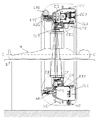
図2に示すように、ドーナツ型の真空容器VVは中心軸がほぼ水平になるように設置してあり、図示しない真空ポンプによって排気口VCから高真空状態にいつも排気されている。図2又は図4に示すように、この真空容器VVの内部の真空空間に円筒状の陰極側回転体組立CRがあり、陰極側回転体組立CRは常温で液体である液体金属を潤滑剤とした動圧滑り軸受から成る軸受機構CBGによって真空中で回転自在に支承されており、これらの中心軸はCC’に一致している。陰極側回転体組立CRには電子銃組立EGが周方向に分離して3個取り付けてある。図2又は図4に示すように、陰極側回転体組立CRには銅でできた円筒状のロータRT2が同軸状に取り付けられており、これと同軸状に磁性体から成る磁路円筒が取り付けられている。ロータRT2に対向した状態で真空容器VVの外側において真空容器壁に沿って円弧状のステータLM2が取り付けられている。前記のロータRT2は前記の磁路円筒とステータLM2で挟まれた状態に配設されている。ロータRT2はステータLM2から真空容器VVの非磁性の材質で出来た壁を通して電磁誘導作用を受けて回転トルクを与えられるので陰極側回転体組立CRは回転する。陰極側回転体組立CRは動圧滑り軸受から成る軸受機構CBG内の液体金属潤滑剤を通して電気的にも熱的にも真空容器VVに接続されている。
【0014】
図4に示すように、電子銃組立EGの先端部には熱電子2を放出する陰極1が取り付けられている。この陰極1の周回軌道に対向した状態で環状のX線ターゲットTGが取り付けられている。図2に示すように、X線ターゲットTGは円筒状の陽極側回転体組立ARに機械的に結合されている。陽極側回転体組立ARは常温で液体である液体金属を潤滑剤とした動圧滑り軸受から成る軸受機構ABGを介して真空容器VVの一部に回転自在に取り付けられている。陽極側回転体組立ARには銅管でできたロータRT1が取り付けられており、これと同軸状に磁性体から成る磁路円筒が取り付けられている。ロータRT1に対向した状態で真空容器VVの外側において真空容器壁に沿って円弧状のステータLM1が取り付けられている。前記のロータRT1は前記の磁路円筒とステータLM1で挟まれた状態に配設されている。ロータRT1はステータLM1から真空容器VVの非磁性の材質で出来た壁を通して電磁誘導作用を受けて回転トルクを与えられるので陽極側回転体組立ARは回転する。X線ターゲットTGの回転中心軸と前記電子銃組立EGの陰極1の周回中心軸CC’とは一致しており、陰極1は常にX線ターゲットTGの表面と対向した状態で両者は互いに反対方向に回転する。
【0015】
図2又は図4を参照して陰極給電機構SL1について説明する。図2又は図4に示す実施例では3個の陰極給電機構SL1が同軸状に取り付けられており、3本の独立した電流通路を形成している。これらの図では陰極給電機構SL1の内部構造は簡略化して表している。電子銃組立EGの陰極1は、真空容器VV内の真空空間で電子銃組立EGの周回中心軸CC’と実質的に同じ中心軸を持つ環状の陰極給電機構SL1を通して高電圧端子HTに電気的に接続されている。高電圧端子HTには真空容器VVの外に在る図示しない高電圧電源からおよそー150KVの負の高電圧と電子銃組立EGの陰極1を加熱する電力が供給される。それぞれの陰極給電機構SL1は固定部と回転部を有し、固定部は絶縁体220を介して電気絶縁を保ちながら真空容器VVの一部に機械的に固定されている。陰極給電機構SL1の回転部と固定部は、液体金属を潤滑剤とする動圧滑り軸受を構成しており、液体金属潤滑剤を介して両者間で通電される。陰極給電機構SL1の回転部が電子銃組立EGに弾力性のある回転トルク伝達機構217で機械的に連結されており、陰極給電機構SL1は、ある程度の偏芯及び軸方向の変位を許容しながら電子銃組立EGと共に回転する。
【0016】
X線ターゲットTGは陽極側回転体組立ARの軸受機構ABG内に在る液体金属潤滑剤を介して電気的にも熱的にも真空容器VVに接続されている。真空容器VVは接地電位になっており、冷却水等で強制冷却されている。従って、X線ターゲットTGは接地電位に設定されると共に、X線ターゲットTGから発生した多量の熱は液体金属潤滑剤を介して真空容器VVの壁の部分を流れる冷却水で効率良く取り去られる。X線ターゲットTGと冷却水との間の熱抵抗は十分に小さいのでX線ターゲットTGの温度は低く保たれる為に大電力の入力が許容され、極めて多量のX線を短時間に発生することができる。
【0017】
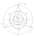
電子銃組立EGは、図3に示すF1,F2,F3のように陰極側回転体組立CRの周囲に等配に3個取り付けられている。ここで、F1,F2,F3は前記の電子2が加速されてX線ターゲットTGに衝突してできるX線の3つの焦点を示している。X線焦点F1,F2,F3は同時にX線を発生させながら図3に示すように同時に同じ方向に周回する。これらのX線焦点の現在位置は陰極側回転体組立CRに取り付けられた角度検出機構(図示せず)によって検出される。X線焦点F1,F2,F3から放射されたX線は、図2又は図4に示すようにX線ターゲットTGの内側にあるX線分布制限機構によってファン状に整形され、陰極側回転体組立CRに取り付けられたファン方向分布整形器WF(図4参照)を通過してファン方向のX線強度分布を適正化された後に真空容器VVのX線放出窓XW(図4参照)を通過し、外部の環状のスリットSLTを通過した後に、被検体Mを通過してX線ターゲットTGと同軸状に取り付けられた2個の環状のX線検出器DF,DBのそれぞれの対向面に到達する。
【0018】
図3に示すように、X線焦点F1,F2,F3から出たX線は、それぞれが検出器の対向する部分D1,D2,D3にある細分化された検出素子で受信される。検出器の部分D1,D2,D3は互いに重ならないように照射野範囲などが決められている。検出器の部分D1,D2,D3の合計は環状検出器のほとんど全体を占めるのでX線検出器DF,DB内の全ての検出素子が有効に活用され、コスト対性能比が改善される。環状の検出器DF,DBはそれぞれが中心軸CC’の方向にも多数の検出素子列に分けられており、それぞれの検出素子で検出された信号は図示しない電子回路でデジタル信号に変換され、図示しないコンピュータで断層像に再構成され、図示しない画像表示装置に表示されてマルチスライスのCT画像を得ることができるようになっている。
【0019】
ある瞬間に鉛直上方に位置した状態における電子銃組立周辺の断面の一部を拡大して図4に示しており、同じ部分は同じ記号を付している。図4において、軸受機構CBGの内部構造は簡略化して表している。陰極側回転体組立CRは全体的に見ると概略回転対称構造であり、これに取り付けられた電子銃組立EG等の部品は小型で軽量であるので10rps程度の高速回転に十分耐えることができる。この場合、X線焦点が3個であるのでスキャン時間は0.03秒まで短縮することができる。X線ターゲットTGは直径が120cmと大型であり、X線焦点F1,F2,F3と反対方向に回転しており、前記のように強制冷却されているのでX線ターゲットTGの表面温度が高くなり難く、大電力の入力が許容されるので短時間に十分な量のX線を発生することができ、超高速スキャンであるにもかかわらずフォトンノイズが少ない良質なCT画像を得ることができる。また、マルチスライススキャンを実現しているのでX線の有効利用ができ、中心軸CC’と平行な方向の解像度を高めることもできるだけでなく、広い範囲の撮影を短時間で完了して3次元のリアルタイムCT画像を得ることができる。
【0020】
上記の構成のX線CTスキャナを実現する為に避けて通れないのは、前記の機器構成で実用できる軸受機構CBG、ABG、及び前記の陰極給電機構SL1の回転部分を真空中で回転自在に支承する動圧滑り軸受を実現させることである。従来は、直径が5cm以下である小型で且つ軸受の開口が片側のみにある動圧滑り軸受は実用化されている。この場合には、動圧滑り軸受の内部に挿入された液体金属潤滑剤は軸受の開口における表面張力の作用で軸受の開口より内側に留められていた。動圧滑り軸受の十分な軸受圧力を得る為には回転部分と固定部分のギャップのサイズは数十μmに限定されていた。例えば開口部におけるギャップのサイズが50μmの場合には液体金属潤滑剤の高低落差がおよそ18cmを超えると、重力加速度による液体金属潤滑剤の静圧力が軸受の開口における表面張力に打ち勝って液体金属潤滑剤が外部に漏出する。このことは、軸受の回転部分が回転を停止したときに深刻な問題となる。特に、本発明の場合のように軸受の開口の周方向における高低落差が100cm程度の動圧滑り軸受は従来の技術では実現不可能であった。
【0021】
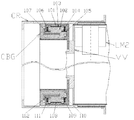
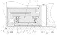
図5と図6とを参照して動圧滑り軸受から成る軸受機構CBGの実施例について説明する。図5は陰極側回転体組立CRと陰極側の軸受機構CBGの断面の一部を拡大して表しており、図5の上方の部分は実使用時において、ある瞬間に鉛直上方に位置する部分を示し、下方の部分は同じ瞬間に鉛直下方に位置する部分を示している。図5においては中央部を省略して短縮して表示している。図6は図5の下方に位置する一部分の拡大図であり、軸受機構CBGの断面を表している。陰極側回転体組立CRには軸受機構CBGの回転部分である軸受回転体102が同軸状に取り付けてある。軸受回転体102には軸受機構CBGの固定部分である軸受固定体101がギャップを有して嵌め合わせてある。軸受固定体101の一部は真空容器VVに機械的及び熱的に結合されている。真空容器VVは図示しない支持架台に取り付けられており、設置床に対して適正な姿勢及び水平方向の位置が保てるようになっている。軸受固定体101と軸受回転体102とは互いに対向した面を有し、この対向した面は第一の軸受ギャップ103、108、第二の軸受ギャップ104,109、第三の軸受ギャップ106、111を有している。これらの軸受ギャップを構成する対向面の少なくとも一方にはヘリンボーン状の軸受溝がある。第一、第二、第三の軸受ギャップ内には常温で液体である液体金属、好適にはガリウム、インジューム、鈴の合金からなる潤滑剤が充填されており、それぞれの軸受ギャップは、ラジアル軸受と、これを挟んで互いに距離をもって対向して取り付けられた第一のスラスト軸受、及び第二のスラスト軸受のそれぞれの軸受ギャップと一致している。軸受ギャップ103と108、軸受ギャップ104と109、軸受ギャップ106と111とはそれぞれ同一のものであり、異なる番号は示す位置の違いを表している。ここで、軸受ギャップとは対向する面の少なくとも一方に前記の軸受溝を有していることを示している。
【0022】
陰極側回転体組立CRに回転トルクが与えられた場合には、これらの軸受内に動圧力が生じるので回転部分を浮上させて回転自在に支承することができる。軸受回転体102が回転している場合にはそれぞれのギャップ内の液体金属潤滑剤は、軸受の内部に閉じ込める作用を受けるので軸受のギャップから外部の真空空間に漏出することは無い。
【0023】
図5及び図6に示すように、前記の軸受固定体101と軸受回転体102が構成する対向面には第一の端部ギャップ105、110、第二の端部ギャップ107、112があり、ラジアル軸受の軸受ギャップ103,108と、第一の端部ギャップ105,110、及び第二の端部ギャップ107,112とを構成する対向面の中心軸は概略水平方向になった状態でCC’に一致している。前記の第一のスラスト軸受の軸受ギャップ104,109、及び第二スラスト軸受の軸受ギャップ106,111を構成するそれぞれの対向面は平面状になっており、第一のスラスト軸受の軸受ギャップ104,109はラジアル軸受の軸受ギャップ103,108と第一の端部ギャップ105,110とに、第二のスラスト軸受の軸受ギャップ106,111はラジアル軸受の軸受ギャップ103,108と第二の端部ギャップ107,112とに連通している。第一の端部ギャップ105,110と第二の端部ギャップ107,112を構成するそれぞれの対向面の直径はラジアル軸受の軸受ギャップ103,108を構成する対向面の直径より小さくなっている。第一の端部ギャップ105,110のサイズと第二の端部ギャップ107,112のサイズはラジアル軸受の軸受ギャップ103、108のサイズよりも大きくなっており、第一の端部ギャップ105,110と第二の端部ギャップ107,112は両方とも真空空間と連通しており、それらを構成する対向面には前記の液体金属潤滑剤で濡れない表面(図示せず)を持っている。第一のスラスト軸受の軸受ギャップ104,109と第一の端部ギャップ105、110との間には環状の軸受開口121、121’があり、第二のスラスト軸受の軸受ギャップ106、111と第二の端部ギャップ107、112との間には環状の軸受開口120、120’がある。これらの軸受開口は、前記の液体金属潤滑剤で濡れない表面とこれで挟まれたギャップを持っており、前記の液体金属潤滑剤が存在する領域と真空空間との実質的な境界を形成している。軸受開口120、120’と軸受開口121、121’を構成するそれぞれの対向面の直径は、ラジアル軸受の軸受ギャップ103,108を構成する対向面の直径より小さくなっている。端部ギャップ105と110、端部ギャップ107と112、軸受開口120と120’、軸受開口121と121’とはそれぞれ同一のものであり、異なる番号は示す位置の違いを表している。軸受開口120’、121’はそれぞれ軸受開口120,121の鉛直上方に位置する部分を意味しているが図面では表示していない。ここで、端部ギャップとは対向する面の少なくとも一方に前記の濡れない面を有していることを示している。
【0024】
図6を参照してギャップサイズ可変機構の構造について説明する。ここでは、図示されている鉛直下方のみについて述べるが、回転対称の構造であることを理解されたい。軸受固定体101には、環状の薄板で出来ており弾力性がある接続機構195、196があり、この接続機構には可動環板140,141が取り付けられており、この可動環板140,141は、それぞれ第二のスラスト軸受及び第一のスラスト軸受の、軸受回転体102に在る軸受面に対向して取り付けられている。第一のスラスト軸受の軸受ギャップ109を構成する対向面の内の一つの面は軸受回転体102の表面にあり、回転中心軸CC’に垂直な面で構成されており、対向面の他の一つの面は前記の可動環板141の表面上に在ってこれらの両方の面は軸受ギャップ109を構成して対面している。前記の可動環板141が回転中心軸CC’の方向に移動することにより第一スラスト軸受の軸受ギャップ109のサイズが変化出来るようになっている。第二のスラスト軸受の軸受ギャップ111を構成する対向面の内の一つの面は、軸受回転体102の表面に在って回転中心軸CC’に垂直な面で構成されており、対向面の内の他の一つの面は、前記の可動環板140の表面上にあり、これらの両方の面は軸受ギャップ111を構成して対面している。前記の可動環板140が回転中心軸CC’の方向に移動することにより第二スラスト軸受の軸受ギャップ111のサイズが変化出来るようになっている。前記のように、可動環板140,141は弾力性がある接続機構195、196によって軸受固定体101に接続されているので可動環板140,141に回転軸CC’の方向の力が働くと容易に回転中心軸CC’の方向に移動できるが半径方向には移動し難いように作られている。図6の実施例では可動環板140,141が軸受固定体に環状の接続機構で繋がっており、回転しないようになっている。また、軸受機構内の液体金属潤滑剤は可動環板140,141及び接続機構195、196の部分では前記の軸受開口120,121以外には真空容器の真空空間に連通しない構造と成っている。
【0025】
次に、図6を参照してギャップサイズ可変機構の作用について説明する。手始めとして、ギャップサイズ可変機構をスラスト軸受に取り付けた理由について説明する。軸受開口120では、液体金属潤滑剤で濡れない表面において液体金属潤滑剤に表面張力が作用し、前記の軸受回転体102が回転を停止した場合にも液体金属潤滑剤が外部に漏出するのが防止される。重力加速度による液体金属潤滑剤内の静圧力は液体金属潤滑剤の喫水線からの深さに比例する。言い換えると、鉛直下方に位置するに従って液体金属潤滑剤内の静圧力が、より大きいことになる。一方、前記の表面張力による圧力効果は軸受ギャップのサイズに反比例する。従って、軸受開口120のギャップのサイズを十分に小さくしておくと大きな直径を持つ動圧滑り軸受の内部から液体金属潤滑剤が漏出するのを防止することができる。
【0026】
しかるに、本発明に使用される軸受の直径が100cm程度と大きい為にラジアル軸受のギャップのサイズは十分に小さな値に保つことが困難である。その一つの理由は、軸受回転体が10rps程度の高速回転をすると、この部分の遠心力による膨張が20μm程度生じる為に軸受ギャップのサイズを17μm程度に保つことは極めて困難であることである。第二の理由は、直径が大きい為に回転部分の熱膨張差が大きくなり、軸受ギャップのサイズを精度良く保つのが困難であることである。従って、ラジアル軸受に軸受開口があるとこの部分のギャップのサイズが大きくなるので大きな表面張力を発生させることが極めて困難であり、軸受機構内の液体金属潤滑剤が軸受機構から真空空間に漏出するのを防止するのは極めて困難である。
【0027】
本発明に使用される第一のスラスト軸受と第二のスラスト軸受の間隔は10cm以下であり、熱膨張の影響を小さく保つことができる。また、軸受ギャップを構成する面は回転軸CC’方向に垂直であるので遠心力の影響を無視できる。更に、スラスト軸受の軸受面は平面であるので加工精度を十分に高めることも容易であり、軸受ギャップのサイズを高精度に保つことは容易にできる。従って、スラスト軸受の軸受ギャップのサイズを十分に小さく保つことができる。例えば、軸受ギャップのサイズを17μmに保った場合には120cm以上の高低落差がある液体金属潤滑剤内の静圧力に打ち勝つ表面張力の圧力効果を発生させることができる。従って、真空空間との全ての実質的な境界をこのようにギャップのサイズが小さいスラスト軸受の端部に設けた軸受開口120,及び軸受開口121に限定することにより簡単に前記の液体金属潤滑剤をこれらの軸受開口の内部に閉じ込めることができ、液体金属潤滑剤が漏出しない動圧滑り軸受を実現することができる。
【0028】
上記のように、軸受回転体102が静止している場合にはスラスト軸受の軸受ギャップ111のサイズ、及びスラスト軸受の軸受ギャップ109のサイズを17μm以下に小さくすることで、液体金属潤滑剤が軸受開口120、及び軸受開口121よりも真空空間側に漏れないようにできる。しかしながら、スラスト軸受の軸受ギャップのサイズが一定値である場合には、軸受回転体102が高速度で回転しているときには、軸受ギャップのサイズが小さ過ぎて回転トルクが過大となって軸受損失が過大となることがある。これを避ける為に予めスラスト軸受の軸受ギャップのサイズを例えば50μm程度の大きな値に一定にしておくと、前記の軸受開口120、及び軸受開口121での液体金属潤滑剤の表面張力の圧力効果が液体金属潤滑剤内の静圧力よりも小さくなって軸受開口120、及び軸受開口121から真空空間側に液体金属潤滑剤が漏出する。軸受の動圧力は軸受回転体の回転速度に大きく影響を受けるので、軸受ギャップのサイズを一定にした場合には、軸受ギャップのサイズの高度な精度管理が必要となり、高価となるだけでなく例えば液体金属潤滑剤との反応や熱膨張などに起因する軸受ギャップのサイズの変化によって軸受機構の回転特性に悪影響が生じる。
【0029】
本発明を採用すると、前記のようにスラスト軸受の軸受ギャップのサイズは容易に回転中心軸CC’方向に変化するので軸受回転体102の回転速度が大きく変化してもスラスト軸受における動圧力は弾力性がある接続機構195、196の回転中心軸CC’方向の剛性のみに依存する。この接続機構195、196の回転中心軸CC’方向の剛性を小さくしておくとスラスト軸受の動圧力はいつもほぼ一定の値に出来る。また、他の実施例で示すように接続機構195、196の剛性を調整できるようにしておくとスラスト軸受の動圧力は任意の値に決めることが出来る。本発明のX線CTスキャナでは回転中心軸CC’は実質的に水平方向にあるのでスラスト軸受は重力加速度の影響が小さく、スラスト軸受の動圧力を小さな値に保っていても問題ない。スラスト軸受に動圧力が生じているときには液体金属潤滑剤を軸受内に引き込む作用があり、軸受開口120、及び軸受開口121から液体金属潤滑剤が漏出することは無い。
【0030】
上記のように、この発明を採用すると、真空空間と連通する前記の軸受開口120、及び軸受開口121の直径が100cmを超える場合において、軸受回転体102が静止している時にも回転している時にも液体金属潤滑剤が軸受機構CBGの外部の真空空間に漏出しないで安定な動作をする動圧滑り軸受を提供することができる。陽極側回転体組立ARに使用している動圧滑り軸受から成る軸受機構ABGも同様の構造と成っている。また、本発明を実施する場合に必須である陰極給電機構SL1に使われている動圧滑り軸受から成る軸受機構も同様の構造と成っている。
【0031】
軸受固定体101は外部から強制冷却されている真空容器VVに熱的にも結合してあるのでこの部分は低い温度に保つことができる。軸受回転体102は、ラジアル軸受、第一、第二のスラスト軸受の軸受ギャップ内にある液体金属潤滑剤を介して軸受固定体101に熱的に結合されており、十分に低い温度に保つことができる。また、軸受回転体102には陰極側回転体組立CRが機械的に結合してあり、陰極側回転体組立CRには電子銃組立EGなどの発熱体が取り付けてある。特に、陽極側の軸受機構AGBでは多量の熱を発生するX線ターゲットTGから多量の熱が流入する。これらの場合でも、上記の理由により、軸受部分の温度を十分に低く保つことができる。
【0032】
他の実施例について図7と図8を参照して説明する。図7に示す実施例では、スラスト軸受の軸受ギャップ111,109を構成する対向面の一つを可動環板201,202の表面とし、可動環板201,202は弾力性がある接続機構195、196を介して軸受回転体102に繋がっている。図7の場合には接続機構195、196が軸受回転体102の半径が大きい側の端部に結合されており、剛性が小さく成っているので動圧力が小さい場合、例えば軸受面積が小さい場合や回転速度が小さい場合に適する。図8の場合には接続機構195、196が軸受回転体102の半径が小さい側の端部に結合されており、剛性が比較的大きく成っているので動圧力が大きい場合、例えば軸受面積が大きい場合や回転速度が大きい場合に適する。いずれの場合にも、可動環板201,202は軸受回転体と共に回転しており遠心力の影響を受ける。遠心力によって軸受ギャップが広がるように成っているので、回転速度が大きくなった場合にも動圧力の増大を防げる。また、図7又は図8の構造では、スラスト軸受の動圧力が大きくなって軸受ギャップ111、109のサイズが大きくなった場合には、軸受開口120,121のギャップのサイズよりも真空空間側のギャップのサイズの方が小さく、この部分では液体金属潤滑剤に濡れない表面を持っているので液体金属潤滑剤の表面張力が大きく、液体金属潤滑剤の漏出防止効果が大きい。
【0033】
更に他の実施例について図9を参照して説明する。これは、図8の場合の改良であり、可動環板201,202は軸受回転体102から突き出たギャップ制限機構207,208によって移動範囲が制限されている。この結果、スラスト軸受を構成する最小の軸受ギャップのサイズが決められ、これよりも軸受ギャップのサイズが小さくならないのでスラスト軸受の動圧力が非線形に制御されることに成る。従って、回転立ち上がり時に回転トルクが大きくなり過ぎないように出来る。
【0034】
更に他の実施例について図10を参照して説明する。これは、図6の場合の改良であり、前記の接続機構195、196の剛性を任意に調整する機能を持っている。前記の軸受固定体101にはギャップサイズ調整機構204,206が設けてあり、これらは例えばスプリングで出来た圧力伝達機構203,205を介して可動環板201,202に繋がっている。ギャップサイズ調整機構204,206は例えばネジで出来ており、これの出し入れによって可動環板201,202に加えられる圧力が調整される。また、他の実施例としてギャップサイズ調整機構204,206を例えば電磁石で構成し、真空容器VVの外にある制御器(図示せず)に電気的に接続してあり、この制御器で可動環板201,202にかかる圧力を遠隔調整することが出来る。この場合には回転特性が最適になるように外部から調整できるので好ましい状態に出来る。また、前記の制御器から交流の電流を供給してギャップサイズ調整機構204,206から可動環板201,202に微小振動を与えると軸受ギャップに液体金属潤滑剤が供給されやすくなり、軸受回転体102の始動時の回転トルクが減少して更に好ましい状態になる。
【0035】
本発明を実施例に関連して説明したが、本発明は、ここに例示した実施例の構造及び形態に限定されるものではなく、本発明の精神及び範囲から逸脱することなく、いろいろな実施形態が可能であり、いろいろな変更及び改変を加えることができることを理解されたい。例えば、この発明では電子銃組立が3個取り付けてあるが1個でも3個以上でも良い。また、この発明では陰極側回転体組立CRとX線ターゲットTGの両方を回転させる構造を示しているが、X線ターゲットTG及びこれに繋がっている部分を固定にした構造のカソードスキャン型X線発生器、及びこれを使ったX線CTスキャナを含む事は勿論である。また、軸受固定体101は真空容器の一部として構成しても良いことは勿論である。更に、上記の実施例では常温で液体である液体金属を潤滑剤として使用した例を示しているが、やや高い融点を持っており常温で固体であっても動作の前に加熱して液化させてから動作させれば同じ効果が得られることは勿論である。更に、前記のX線ターゲットから発生したX線を前記の真空容器の外に取り出す為のX線放出窓は真空容器と一体になっていても、真空容器の一部として構成されていてもこの部分でのX線の減衰率が小さければX線放出窓と見なすことが出来るのは勿論である。真空容器VVは回転対称な形状でなくても良い事は勿論である。真空容器の中心軸と陰極側回転体組立又は陽極側回転体組立の中心軸がある程度ずれていても良い事は勿論である。X線ターゲットが分割して構成されており、それぞれの分割された部分に隙間があっても良い事は勿論である。陰極給電機構の回転部分は、この陰極給電機構の軸受機構を構成する軸受回転体そのものであっても良い事は勿論である。陰極給電機構は、軸受機構CBGと一体に構成されていても良い事は勿論である。尚、本発明では、ギャップのサイズとは、ギャップを構成する対向面の一方の面上の任意の点から、このギャップを構成する対向面の他方の面への最短の距離を意味している。
【0036】
この発明は、これまで述べてきたように超高速スキャンができるX線CTスキャナを実現させるものであるが、次のように小変更することにより周回中心軸方向に向かって全周囲方向から電子線を照射する電子線照射装置に応用することができる。即ち、前記の実施例で説明した機器構成からX線ターゲット及びこれに関する部分と、X線のX線分布制限機構及びファン方向分布整形器WF及びその他のX線に関する部品を省略して、X線放出窓XWを薄いチタン板から成る電子線放出窓に変更し、電子銃組立EGから電子を放出する方向を電子線放出窓の方向に変えるだけでそのまま実用になる。これを使用すると、プラスチックやガラスやその他の改質処理に使用できて工業的に大きな効果を得る電子線照射装置を提供することができる。
【0037】
【発明の効果】
以上説明したように、本発明のカソードスキャン型X線発生器を採用すると、回転する部分を真空容器内部の概略回転対称な構造体に軽い部品を取り付けた構造にできるので遠心力の影響が少なくなり、例えばスキャン時間が0.03秒の超高速スキャン型X線CTスキャナを簡単な構造で安価に実現させることができる。特に、複数のX線焦点から同時に短時間に多量のX線を発生することができ、フォトンノイズが少ない十分に良質な画像を得ることができる。発生したX線は環状の面検出器で有効に受信され、広い範囲の領域における多数の断面を瞬時に撮影することができ、このデータを使用して被検体の3次元の内部構造を瞬時に検査できるようになる。その為に例えば人間の心臓のように動きが速い部分が被検体の内部にあっても、これを忠実に即時性をもって撮影できる超高速X線CTスキャナを提供することができる。軸受機構には液体金属を潤滑剤とした動圧滑り軸受を採用しているので真空中で長時間にわたって安定に使用できるだけでなく、回転している部分の電位を一定に保つことができて微小放電などの不安定な現象の発生を防止できる。さらに、動圧滑り軸受を通して内部で発生した熱を有効に真空容器の外部に導いて冷却することができる。動圧滑り軸受から液体金属潤滑剤が漏出することなく軸受の動圧力を適正化できるので、真空容器内での回転部分は良好な回転特性を長時間にわたって維持することが出来る。外部に機械的な回転機構がなく、これに関連した電源や電子回路は静止状態で使用できるので全体として信頼性がよく、X線CTスキャナ全体がコンパクトになる。
【図面の簡単な説明】
【図1】従来のX線CTスキャナの概略の断面を表す図である。
【図2】本発明に係わるカソードスキャン型X線発生器、及びこれを使ったX線CTスキャナの全体構造体の主要部の概略の断面である。
【図3】本発明に係わるカソードスキャン型X線発生器、及びこれを使ったX線CTスキャナの原理を説明する図である。
【図4】本発明に係わるカソードスキャン型X線発生器の、ある瞬間に鉛直上方に位置する一部分の断面を拡大した図である。
【図5】本発明に係わるカソードスキャン型X線発生器の主要部である陰極側回転体組立の部分を拡大した断面図である。
【図6】本発明に係わるカソードスキャン型X線発生器の主要部を表す図5の一部を更に拡大した断面図である。
【図7】本発明に係わるカソードスキャン型X線発生器の他の実施例に関する、図6に相当する断面図である。
【図8】本発明に係わるカソードスキャン型X線発生器の他の実施例に関する、図6に相当する断面図である。
【図9】本発明に係わるカソードスキャン型X線発生器の他の実施例に関する、図6に相当する断面図である。
【図10】本発明に係わるカソードスキャン型X線発生器の他の実施例に関する、図6に相当する断面図である。
【符号の説明】
ABG 陽極側の軸受機構
AR 陽極側回転体組立
B 寝台
CBG 陰極側の軸受機構
CR 陰極側回転体組立
DB 後方検出器組立
DF 前方検出器組立
D1 検出器DF,DBの一部
D2 検出器DF,DBの一部
D3 検出器DF,DBの一部
EG 電子銃組立
F1 X線焦点
F2 X線焦点
F3 X線焦点
HT 高電圧端子
LM1 円弧状のステータ
LM2 円弧状のステータ
M 被検体
RT1 円筒状のロータ
RT2 円筒状のロータ
SL1 陰極給電機構
SLT スリット
TG X線ターゲット
VC 排気口
VV 真空容器
WF ファン方向分布整形器
XW X線放出窓
1 陰極
2 電子ビーム
101 軸受固定体
102 軸受回転体
103 ラジアル軸受ギャップの鉛直上方部分
104 第一スラスト軸受の軸受ギャップの鉛直上方部分
105 端部ギャップの鉛直上方部分
106 第二スラスト軸受の軸受ギャップの鉛直上方部分
107 端部ギャップの鉛直上方部分
108 ラジアル軸受ギャップの鉛直下方部分
109 第一スラスト軸受の軸受ギャップの鉛直下方部分
110 端部ギャップの鉛直下方部分
111 第二スラスト軸受の軸受ギャップの鉛直下方部分
112 端部ギャップの鉛直下方部分
120 第二スラスト軸受の軸受開口
121 第一スラスト軸受の軸受開口
140 可動環板
141 可動環板
190 環状の窪み
191 環状の突起
193 環状の窪み
194 環状の突起
195 接続機構
196 接続機構
197 環状の窪み
198 環状の空洞
199 環状の窪み
200 環状の空洞
201 可動環板
202 可動環板
203 圧力伝達機構
204 ギャップサイズ調整機構
205 圧力伝達機構
206 ギャップサイズ調整機構
207 ギャップ制限機構
208 ギャップ制限機構
217 回転トルク伝達機構
220 絶縁体
1001 従来のX線CTスキャナの固定架台
1002 従来のX線CTスキャナの回転架台
1003 従来のX線CTスキャナの軸受
1004 従来のX線CTスキャナのX線管
1005 従来のX線CTスキャナのX線
1006 従来のX線CTスキャナの検出器
1007 従来のX線CTスキャナの電子回路
1008 従来のX線CTスキャナの制御器
1009 従来のX線CTスキャナの回転駆動機構[0001]
[Technical field to which the invention belongs]
The present invention is a cathode scan X-ray generator for an X-ray CT scanner capable of performing ultra-high-speed scanning by emitting X-rays from an X-ray focal point that circulates at high speed while being small, and ultra-high-speed scanning using the same The present invention relates to an X-ray CT scanner. By limiting the mechanism that circulates the X-ray focal point to small components in the vacuum vessel, the X-ray focal point can be stably circulated around the specimen at a high speed without having a mechanical rotation mechanism in the atmosphere. Thus, a small X-ray CT scanner is provided that can instantly image a subject and obtain a three-dimensional image. An electron gun assembly is circulated in a vacuum vessel using a dynamic pressure sliding bearing using a liquid metal as a lubricant, and a component rotating in the vacuum vessel is energized from outside the vacuum vessel.
[0002]
[Prior art]
A conventional X-ray CT scanner will be described with reference to FIG. A conventional X-ray CT scanner has a
[0003]
An
It has not been possible with a conventional X-ray CT scanner to satisfy these conflicting requirements at the same time.
[0004]
On the other hand, electronic scanning X-ray CT scanners have been developed in the past to increase scanning speed. This is because the electrons are taken out from the electron gun assembly fixed at the bottom of the vacuum vessel in the shape of a thermos placed on its side, and the position of the electrons is electromagnetically controlled while traveling about 100 cm in the vacuum vessel. After circling around the subject, the electrons are incident on an arc-shaped X-ray target to extract X-rays that circulate halfway. With this structure, a high-speed scan with a scan time of about 0.1 seconds can be performed, but the image quality is poor due to the inability to obtain a sufficient X-ray dose, the focus of X-rays is too large, However, it has drawbacks such as difficulty in maintaining a stable operation, large size of the apparatus which is difficult to handle, and high cost, and is only used for special purposes.
[0005]
[Problems to be solved by the invention]
The problem to be solved is that the scanning time of the X-ray CT scanner is greatly shortened to eliminate motion artifacts in capturing a fast-moving subject and ensure a sufficient level of X-ray dose to reduce photon noise. It is an object to provide an X-ray CT scanner that can obtain an accurate image, is small in size, and is easy to handle. In particular, as a bearing mechanism that can be used reliably in a vacuum to achieve this, and a power supply mechanism that can supply power to components rotating in a vacuum, an annular dynamic pressure that uses a liquid metal as a lubricant during operation. Despite the development of a plain bearing, despite the large diameter of this bearing and the high head drop of the bearing opening, liquid metal lubricant does not leak out of the bearing mechanism and the dynamic pressure of the thrust bearing is always appropriate. It is an object to provide a cathode scan X-ray generator having a mechanism for maintaining a value, and an X-ray CT scanner using the same.
[0006]
[Means for Solving the Problems]
In the present invention, all the rotating parts of the X-ray CT scanner are mounted in a doughnut-shaped vacuum container so as to be reduced to the minimum, and the X-ray CT scanner can perform ultra-high speed scanning by eliminating mechanical rotating parts in the air. A line CT scanner is realized. The vacuum vessel is made in a donut shape, and the subject is placed on a bed in the atmosphere near the central axis of the vacuum vessel. Electrons are emitted from the cathode of the electron gun assembly that circulates in the vacuum vessel, and the accelerated electrons collide with an annular X-ray target mounted in the vacuum vessel so as to face the circular orbit of the cathode and emit X-rays. generate. The generated X-rays are irradiated to a subject in the atmosphere through an X-ray emission window provided on the small-diameter wall of the vacuum vessel. The X-rays that have passed through the subject are detected by an annular X-ray detector that is coaxially arranged in the atmosphere with the vacuum vessel, reconstructed into a tomographic image by a computer, and displayed on a display device. The rotating part for rotating the X-ray focal point in the vacuum vessel is limited to a lightweight electron gun assembly, etc. The volume is small and the overall shape is almost symmetrical, so the rotation period is 0.1 seconds or less. Even if it rotates, the stress applied to the rotating body can be sufficiently reduced, and high-speed rotation can be continued stably. In addition, since about three electron gun assemblies are attached to the same cathode side rotating body assembly, an ultra-high speed scan with a scan time of about 0.03 seconds can be performed.
[0007]
X-ray CT scanners of the type that circulates the electron gun portion inside a donut-shaped vacuum vessel have been proposed in the past, but have not been realized so far. One of the reasons is that no means for continuing stable rotation in vacuum and no reliable means for stably setting the potential of the rotating body to a constant value have been found. In the present invention, an annular hydrodynamic slide bearing using a liquid metal that is liquid during operation as a lubricant is used as a bearing mechanism that can be used reliably in a vacuum. The diameter of the bearing is large and the circumference of the opening of the bearing is large. Gap size that allows the size of the bearing gap to be changed so that the liquid metal lubricant does not leak out of the bearing mechanism and the dynamic pressure of the thrust bearing is always maintained at an appropriate value, despite the large height drop in the direction. A variable mechanism is provided. Further, the potential of the rotating body is set to a constant value via the liquid metal lubricant.
[0008]
When the bearing rotating body constituting the rotating portion of the bearing mechanism CBG is rotating, the liquid metal lubricant is confined inside the bearing by the suction action of the bearing groove provided on the surface of the bearing. In general, when the bearing rotating body stops rotating, the surface tension of the liquid metal lubricant generated in the bearing opening that forms a substantial boundary between the area where the liquid metal lubricant exists in the bearing mechanism and the vacuum space causes the liquid. Leakage of the metal lubricant is prevented. However, in the X-ray CT scanner of the present invention, the rotation center axis of the bearing rotating body is substantially in the horizontal direction, and the diameter of the bearing opening is as large as about 100 cm. The liquid metal lubricant in the portion located vertically below the surface is subjected to a large static pressure by the acceleration of gravity. In order to obtain a surface tension large enough to overcome this static pressure, it is necessary to make the gap of the bearing opening extremely small and to give this portion a surface that is not wetted by the liquid metal lubricant. In order to realize this, the bearing adjacent to the bearing opening is limited to the thrust bearing, and the gap of the thrust bearing is sufficiently narrowed. Since the distance between the thrust bearings is short, the influence of thermal expansion is small, and since there is almost no expansion due to centrifugal force accompanying rotation, this narrow gap can be maintained. In addition, at least one of the opposing surfaces constituting the thrust bearing is configured as an annular movable ring plate connected to the bearing rotating body or the bearing fixed body via an elastic portion. When the bearing rotating body stops rotating due to the pressure adjustment action of this part, the size of the bearing gap decreases, the surface tension at the bearing opening increases, and the bearing rotating body rotates at a high speed. This prevents the bearing gap of the thrust bearing from widening and excessive dynamic pressure from being generated. Therefore, excessive bearing loss does not occur. In addition, when the bearing rotating body rotates at a high speed, the liquid metal lubricant sucks into the bearing due to the effect of the bearing groove, so that the liquid metal lubricant can be removed from the bearing opening even if the bearing gap is widened. There is no leakage into the vacuum area.
[0009]
However, when the liquid metal lubricant protrudes from the bearing opening to the vacuum space side for an unexpected reason, it is preferable to return the liquid metal lubricant into the thrust bearing again. As a means to achieve this, it is in the same plane as the thrust bearing, has a gap that is slightly larger than the bearing gap of the thrust bearing, and is wetted by the liquid metal lubricant. A liquid metal lubricant leakage prevention mechanism with no surface is installed. The gap in this portion is composed of the opposed surfaces of the bearing rotating body and the bearing fixing body, and is larger than the size of the bearing gap of the thrust bearing by, for example, about 1 μm. No. Preferably, the liquid metal lubricant leakage prevention mechanism is on the side having a smaller diameter than the bearing opening. In this case, the liquid metal lubricant that has come out at this position has an effect of returning to the inside of the bearing by the centrifugal force of the surface of the bearing rotating body. More preferably, when the annular recess and the annular projection are provided concentrically in the liquid metal lubricant leakage prevention mechanism, the liquid metal lubricant is trapped in the annular recess, etc. Is prevented from reaching.
[0010]
If the present invention is adopted, the bearing surface is in thermal communication with the vacuum vessel, and the vacuum vessel is forcibly cooled from the outside, so the temperature of the bearing surface does not rise even though there is heat generation in the bearing. The thermal expansion is small and stable operation can be performed for a long time. Furthermore, components that generate heat, such as an electron gun assembly or an X-ray target, are forcibly cooled via the liquid metal lubricant in the bearing gap, and thermal expansion and the like are suppressed.
[0011]
DETAILED DESCRIPTION OF THE INVENTION
The cathode scan type X-ray generator is wrapped in a donut-type vacuum vessel, and this vacuum vessel is installed so that the central axis is almost horizontal, and the subject (human body) is in the atmosphere near the central axis. ) And the vacuum vessel is arranged so as to surround the subject. The vacuum vessel is fixed without rotating, and the angle with the subject and the position in the horizontal direction can be changed. X-rays are generated toward the subject while the X-ray focus moves so that the X-ray focus circulates around the subject in the vacuum space inside the vacuum vessel. By using the circulating X-ray, an X-ray CT scanner having no rotation mechanism in the atmosphere is realized. Cathode scan X-ray generator for X-ray CT scanners that can perform ultra-high-speed scanning, which is impossible to achieve with conventional X-ray CT scanners, and obtain high output, and ultra-high-speed X-rays using the same The CT scanner has a simple structure and is inexpensive and reliable.
[0012]
【Example】
Hereinafter, embodiments of a cathode scan X-ray generator and an X-ray CT scanner using the same according to an embodiment of the present invention will be described with reference to the drawings. 2 is a schematic cross-sectional view of the entire structure of a cathode scan type X-ray generator and an X-ray CT scanner using the cathode scan type X-ray generator of the present invention, FIG. 3 is a principle view, and FIG. 4 is related to the present invention. It is the figure which expanded the section of a part of the cathode scan type X-ray generator located vertically upward at a certain moment, and enlarged a part of the section around the electron gun assembly in the state positioned vertically upward at a certain moment. Show. The same parts are given the same symbols. FIG. 5 is an enlarged cross-sectional view of a part of the cathode side rotating body assembly which is a main part of the cathode scan type X-ray generator of the present invention. FIG. 6 is a cross-sectional view in which the main part of FIG. 5 is further enlarged. 7 to 10 are cross-sectional views showing a portion corresponding to FIG. 6 of another embodiment.
[0013]
As shown in FIG. 2, the donut-shaped vacuum vessel VV is installed so that the central axis is substantially horizontal, and is evacuated from the exhaust port VC to a high vacuum state by a vacuum pump (not shown). As shown in FIG. 2 or FIG. 4, there is a cylindrical cathode-side rotating body assembly CR in the vacuum space inside the vacuum vessel VV. The cathode-side rotating body assembly CR uses a liquid metal that is liquid at room temperature as a lubricant. These bearings are rotatably supported in a vacuum by a bearing mechanism CBG comprising a hydrodynamic sliding bearing, and their central axes coincide with CC ′. Three electron gun assemblies EG are attached to the cathode side rotating body assembly CR so as to be separated in the circumferential direction. 2 or As shown in FIG. 4, a cylindrical rotor RT2 made of copper is coaxially attached to the cathode side rotating body assembly CR, and a magnetic path cylinder made of a magnetic material is coaxially attached thereto. . An arc-shaped stator LM2 is attached along the vacuum vessel wall outside the vacuum vessel VV in a state of facing the rotor RT2. The rotor RT2 is disposed between the magnetic path cylinder and the stator LM2. Since the rotor RT2 receives an electromagnetic induction action from the stator LM2 through the wall made of a nonmagnetic material of the vacuum vessel VV and is given a rotational torque, the cathode side rotating body assembly CR rotates. The cathode side rotating body assembly CR is electrically and thermally connected to the vacuum vessel VV through a liquid metal lubricant in a bearing mechanism CBG composed of a hydrodynamic sliding bearing.
[0014]
As shown in FIG. 4, a
[0015]
The cathode power feeding mechanism SL1 will be described with reference to FIG. 2 or FIG. In the embodiment shown in FIG. 2 or 4, three cathode power feeding mechanisms SL <b> 1 are attached coaxially to form three independent current paths. In these drawings, the internal structure of the cathode power feeding mechanism SL1 is simplified. The
[0016]
The X-ray target TG is electrically and thermally connected to the vacuum vessel VV via a liquid metal lubricant present in the bearing mechanism ABG of the anode side rotating body assembly AR. The vacuum vessel VV is at ground potential and is forcibly cooled with cooling water or the like. Therefore, the X-ray target TG is set to the ground potential, and a large amount of heat generated from the X-ray target TG is efficiently removed by the cooling water flowing through the wall portion of the vacuum vessel VV via the liquid metal lubricant. Since the thermal resistance between the X-ray target TG and the cooling water is sufficiently small, the temperature of the X-ray target TG is kept low, so that high power input is allowed and an extremely large amount of X-rays are generated in a short time. be able to.
[0017]
Three electron gun assemblies EG are attached at equal intervals around the cathode-side rotating body assembly CR, such as F1, F2, and F3 shown in FIG. Here, F1, F2, and F3 indicate three focal points of X-rays that are generated when the
[0018]
As shown in FIG. 3, the X-rays emitted from the X-ray focal points F1, F2, and F3 are received by the subdivided detection elements in the opposing portions D1, D2, and D3 of the detector, respectively. The irradiation field range is determined so that the detector portions D1, D2, and D3 do not overlap each other. Since the sum of the detector portions D1, D2, and D3 occupies almost the entire annular detector, all the detection elements in the X-ray detectors DF and DB are effectively used, and the cost-to-performance ratio is improved. Each of the annular detectors DF and DB is divided into a large number of detection element rows in the direction of the central axis CC ′, and signals detected by the respective detection elements are converted into digital signals by an electronic circuit (not shown). A tomographic image is reconstructed by a computer (not shown) and displayed on an image display device (not shown) so that a multi-slice CT image can be obtained.
[0019]
FIG. 4 is an enlarged view of a part of the section around the electron gun assembly in a state where the electron gun assembly is positioned vertically upward at a certain moment, and the same parts are denoted by the same reference numerals. In FIG. 4, the internal structure of the bearing mechanism CBG is simplified. The cathode side rotating body assembly CR has a generally rotationally symmetric structure as a whole, and components such as the electron gun assembly EG attached thereto are small and light, and can sufficiently withstand high-speed rotation of about 10 rps. In this case, since there are three X-ray focal points, the scan time can be shortened to 0.03 seconds. The X-ray target TG has a large diameter of 120 cm, rotates in the opposite direction to the X-ray focal points F1, F2, and F3 and is forcedly cooled as described above, so the surface temperature of the X-ray target TG becomes high. It is difficult, and high power input is allowed, so that a sufficient amount of X-rays can be generated in a short time, and a high-quality CT image with little photon noise can be obtained despite ultra-high speed scanning. In addition, since multi-slice scanning is realized, X-rays can be used effectively, and the resolution in the direction parallel to the central axis CC ′ can be increased. Real-time CT images can be obtained.
[0020]
What is inevitable to realize the X-ray CT scanner having the above-described configuration is that the rotating portions of the bearing mechanisms CBG, ABG and the cathode power supply mechanism SL1 that can be practically used in the above-described device configuration can be freely rotated in a vacuum. It is to realize a hydrodynamic sliding bearing to be supported. Conventionally, a hydrodynamic slide bearing having a diameter of 5 cm or less and a bearing opening on only one side has been put into practical use. In this case, the liquid metal lubricant inserted into the hydrodynamic sliding bearing is retained inside the bearing opening due to the effect of surface tension at the bearing opening. In order to obtain a sufficient bearing pressure of the hydrodynamic sliding bearing, the size of the gap between the rotating part and the fixed part has been limited to several tens of μm. For example, when the gap size in the opening is 50 μm and the height drop of the liquid metal lubricant exceeds about 18 cm, the static pressure of the liquid metal lubricant due to gravitational acceleration overcomes the surface tension at the opening of the bearing, and the liquid metal lubrication Agent leaks to the outside. This becomes a serious problem when the rotating part of the bearing stops rotating. In particular, as in the case of the present invention, a hydrodynamic slide bearing having a height drop of about 100 cm in the circumferential direction of the opening of the bearing cannot be realized by the conventional technology.
[0021]
With reference to FIG. 5 and FIG. 6, an embodiment of a bearing mechanism CBG composed of a hydrodynamic sliding bearing will be described. FIG. 5 is an enlarged view of a part of the cross section of the cathode side rotating body assembly CR and the cathode side bearing mechanism CBG. The upper part of FIG. 5 is a part positioned vertically upward at a certain moment in actual use. The lower part shows the part located vertically downward at the same moment. In FIG. 5, the central portion is omitted and is shortened. FIG. 6 is an enlarged view of a portion located below FIG. 5 and shows a cross section of the bearing mechanism CBG. A bearing
[0022]
When rotational torque is applied to the cathode side rotating body assembly CR, dynamic pressure is generated in these bearings, so that the rotating portion can be lifted and supported rotatably. When the bearing
[0023]
As shown in FIGS. 5 and 6, there are
[0024]
The structure of the gap size variable mechanism will be described with reference to FIG. Here, only the vertically downward shown is described, but it should be understood that the structure is rotationally symmetric. The bearing fixed
[0025]
Next, the operation of the gap size variable mechanism will be described with reference to FIG. As a start, the reason why the variable gap size mechanism is attached to the thrust bearing will be described. In the
[0026]
However, since the diameter of the bearing used in the present invention is as large as about 100 cm, it is difficult to keep the gap size of the radial bearing at a sufficiently small value. One reason is that if the bearing rotating body rotates at a high speed of about 10 rps, expansion of this portion due to the centrifugal force occurs about 20 μm, so that it is extremely difficult to keep the size of the bearing gap at about 17 μm. The second reason is that since the diameter is large, the difference in thermal expansion of the rotating part becomes large, and it is difficult to keep the size of the bearing gap with high accuracy. Accordingly, if there is a bearing opening in the radial bearing, the size of the gap at this portion increases, so that it is extremely difficult to generate a large surface tension, and the liquid metal lubricant in the bearing mechanism leaks from the bearing mechanism into the vacuum space. It is extremely difficult to prevent this.
[0027]
The distance between the first thrust bearing and the second thrust bearing used in the present invention is 10 cm or less, and the influence of thermal expansion can be kept small. Further, since the surfaces constituting the bearing gap are perpendicular to the direction of the rotation axis CC ′, the influence of centrifugal force can be ignored. Furthermore, since the bearing surface of the thrust bearing is a flat surface, it is easy to sufficiently increase the machining accuracy, and the size of the bearing gap can be easily maintained with high accuracy. Therefore, the size of the bearing gap of the thrust bearing can be kept sufficiently small. For example, when the size of the bearing gap is maintained at 17 μm, the pressure effect of the surface tension that overcomes the static pressure in the liquid metal lubricant having a height difference of 120 cm or more can be generated. Therefore, the liquid metal lubricant can be simply defined by limiting all substantial boundaries with the vacuum space to the
[0028]
As described above, when the bearing
[0029]
When the present invention is adopted, the size of the bearing gap of the thrust bearing easily changes in the direction of the rotation center axis CC ′ as described above, so that the dynamic pressure in the thrust bearing is elastic even if the rotational speed of the bearing
[0030]
As described above, when the present invention is employed, when the diameter of the
[0031]
Since the bearing fixed
[0032]
Another embodiment will be described with reference to FIGS. In the embodiment shown in FIG. 7, one of the opposing surfaces constituting the bearing
[0033]
Still another embodiment will be described with reference to FIG. This is an improvement in the case of FIG. 8, and the
[0034]
Still another embodiment will be described with reference to FIG. This is an improvement in the case of FIG. 6 and has a function of arbitrarily adjusting the rigidity of the
[0035]
Although the invention has been described with reference to exemplary embodiments, the invention is not limited to the construction and form of the embodiments illustrated herein, and various implementations may be made without departing from the spirit and scope of the invention. It should be understood that forms are possible and that various changes and modifications can be made. For example, in the present invention, three electron gun assemblies are attached, but one or three or more may be used. Further, in the present invention, a structure in which both the cathode side rotating body assembly CR and the X-ray target TG are rotated is shown. However, the cathode scan type X-ray having a structure in which the X-ray target TG and the portion connected thereto are fixed. It goes without saying that the generator and an X-ray CT scanner using the generator are included. Of course, the bearing fixed
[0036]
The present invention realizes an X-ray CT scanner capable of ultra-high-speed scanning as described above. However, by making the following small changes, an electron beam is observed from the entire circumferential direction toward the circumferential central axis. It can apply to the electron beam irradiation apparatus which irradiates. That is, the X-ray target and its related parts, the X-ray X-ray distribution limiting mechanism, the fan direction distribution shaper WF and other parts related to X-rays are omitted from the apparatus configuration described in the above embodiment. The emission window XW is changed to an electron beam emission window made of a thin titanium plate, and the electron emission direction from the electron gun assembly EG is changed to the direction of the electron beam emission window. If this is used, the electron beam irradiation apparatus which can be used for plastics, glass, and other modification treatments and has a large industrial effect can be provided.
[0037]
【The invention's effect】
As described above, when the cathode scan type X-ray generator of the present invention is adopted, the rotating part can be made into a structure in which a light part is attached to a roughly rotationally symmetric structure inside the vacuum vessel, so that the influence of centrifugal force is small. Thus, for example, an ultrafast scanning X-ray CT scanner having a scanning time of 0.03 seconds can be realized with a simple structure at low cost. In particular, a large amount of X-rays can be generated simultaneously from a plurality of X-ray focal points in a short time, and a sufficiently high quality image with little photon noise can be obtained. The generated X-ray is effectively received by the annular surface detector, and a large number of cross sections in a wide area can be instantaneously imaged. Using this data, the three-dimensional internal structure of the subject can be instantaneously captured. Can be inspected. Therefore, for example, even if a fast-moving part such as a human heart is inside the subject, it is possible to provide an ultrahigh-speed X-ray CT scanner that can take an image of the object faithfully and immediately. The bearing mechanism uses a hydrodynamic sliding bearing with a liquid metal lubricant, so that it can be used stably for a long time in a vacuum, and the rotating part can be kept at a constant potential. Generation of unstable phenomena such as discharge can be prevented. Further, the heat generated inside through the hydrodynamic sliding bearing can be effectively guided to the outside of the vacuum vessel to be cooled. Since the dynamic pressure of the bearing can be optimized without leakage of the liquid metal lubricant from the hydrodynamic sliding bearing, the rotating portion in the vacuum vessel can maintain good rotational characteristics for a long time. Since there is no mechanical rotation mechanism outside and the power supply and electronic circuit related to this can be used in a stationary state, the overall reliability is good and the entire X-ray CT scanner becomes compact.
[Brief description of the drawings]
FIG. 1 is a schematic cross-sectional view of a conventional X-ray CT scanner.
FIG. 2 is a schematic cross section of a main part of the entire structure of a cathode scan X-ray generator and an X-ray CT scanner using the same according to the present invention.
FIG. 3 is a diagram for explaining the principle of a cathode scan X-ray generator and an X-ray CT scanner using the same according to the present invention.
FIG. 4 is an enlarged view of a section of a portion of the cathode scan X-ray generator according to the present invention positioned vertically upward at a certain moment.
FIG. 5 is an enlarged cross-sectional view of a part of a cathode side rotating body assembly which is a main part of a cathode scan type X-ray generator according to the present invention.
6 is a sectional view further enlarging a part of FIG. 5 showing a main part of the cathode scan type X-ray generator according to the present invention.
FIG. 7 is a cross-sectional view corresponding to FIG. 6 relating to another embodiment of the cathode scan X-ray generator according to the present invention.
FIG. 8 is a cross-sectional view corresponding to FIG. 6, showing another embodiment of a cathode scan X-ray generator according to the present invention.
FIG. 9 is a cross-sectional view corresponding to FIG. 6, showing another embodiment of the cathode scan type X-ray generator according to the present invention.
10 is a cross-sectional view corresponding to FIG. 6, showing another embodiment of the cathode scan X-ray generator according to the present invention.
[Explanation of symbols]
ABG Anode bearing mechanism
AR anode side rotating body assembly
B Sleeper
CBG Cathode side bearing mechanism
CR cathode rotating body assembly
DB Rear detector assembly
DF front detector assembly
Part of D1 detector DF, DB
Part of D2 detector DF, DB
Part of D3 detector DF, DB
EG electron gun assembly
F1 X-ray focus
F2 X-ray focus
F3 X-ray focus
HT high voltage terminal
LM1 Arc-shaped stator
LM2 Arc-shaped stator
M subject
RT1 Cylindrical rotor
RT2 Cylindrical rotor
SL1 Cathode feed mechanism
SLT slit
TG X-ray target
VC exhaust port
VV vacuum vessel
WF Fan direction distribution shaper
XW X-ray emission window
1 Cathode
2 Electron beam
101 Bearing fixed body
102 Bearing rotating body
103 Vertical upper part of radial bearing gap
104 Vertically upper portion of the bearing gap of the first thrust bearing
105 Vertically upper part of the end gap
106 Vertically upper portion of the bearing gap of the second thrust bearing
107 Vertically upper part of the end gap
108 Vertical lower part of radial bearing gap
109 Vertically lower portion of the bearing gap of the first thrust bearing
110 Vertically lower part of the end gap
111 Vertically lower portion of the bearing gap of the second thrust bearing
112 Vertically lower part of the end gap
120 Bearing opening of second thrust bearing
121 Bearing opening of first thrust bearing
140 Movable ring plate
141 Movable ring plate
190 Annular depression
191 Annular projection
193 Annular depression
194 Annular projection
195 connection mechanism
196 connection mechanism
197 annular depression
198 Annular cavity
199 Annular depression
200 Annular cavity
201 Movable ring plate
202 Movable ring plate
203 Pressure transmission mechanism
204 Gap size adjustment mechanism
205 Pressure transmission mechanism
206 Gap size adjustment mechanism
207 Gap limit mechanism
208 Gap limit mechanism
217 Rotational torque transmission mechanism
220 Insulator
1001 Fixed mount for conventional X-ray CT scanner
1002 Conventional X-ray CT scanner rotating mount
1003 Conventional X-ray CT scanner bearing
1004 X-ray tube of conventional X-ray CT scanner
1005 X-ray of conventional X-ray CT scanner
1006 Detector of conventional X-ray CT scanner
1007 Electronic circuit of conventional X-ray CT scanner
1008 Controller for conventional X-ray CT scanner
1009 Conventional X-ray CT scanner rotation drive mechanism
Claims (15)
これらの軸受機構は環状であってその中心軸に沿って前記真空容器の一部分が貫通して構成されており、
これらの軸受機構の内の少なくとも一方の軸受機構は、この軸受機構を固定する部分である環状の軸受固定体と、この軸受固定体に嵌め合わされて回転する環状の軸受回転体とを有し、これらの軸受固定体と軸受回転体との間には動作時に液体である液体金属を潤滑剤とした複数の動圧滑り軸受が構成されており、
それぞれの動圧滑り軸受はギャップを有して対向する軸受面を有しており、これらの軸受面の少なくとも一方にはヘリンボーン状の軸受溝が設けられており、
前記の動圧滑り軸受には回転軸方向に動圧力を生じるスラスト軸受が含まれており、このスラスト軸受の軸受面間のギャップのサイズを変化させられるように構成されたギャップサイズ可変機構が前記の軸受機構に設けられており、
前記軸受機構には前記軸受機構内の液体金属潤滑剤が存在する領域と前記真空空間との実質的な境界を成す環状の軸受開口があり、
この軸受開口はその直径が18cmを超えており、前記軸受開口に経路的に隣接する前記動圧滑り軸受は前記スラスト軸受に限定されており、
前記ギャップサイズ可変機構は、前記軸受回転体が回転を停止した場合には前記スラスト軸受の前記軸受ギャップのサイズを小さくして前記軸受開口における前記液体金属潤滑剤の表面張力を大きくし、前記軸受回転体が高速度で回転している場合には前記スラスト軸受の前記軸受ギャップを広げて過大な動圧力が生じるのを防止するように構成されていることを特徴とするカソードスキャン型X線発生器。A doughnut-shaped vacuum vessel that forms a vacuum space by holding the inside in a vacuum state, and a cathode side that is supported so that it can rotate coaxially with the central axis of the vacuum vessel in the vacuum space inside the vacuum vessel A rotating body assembly, an electron gun assembly attached to a part of the cathode side rotating body assembly, a cathode attached to the electron gun assembly and emitting electrons, and feeding power to the cathode from the outside of the vacuum vessel A rotating portion of the cathode feeding mechanism for performing the operation, an annular X-ray target attached facing the surface including the orbit of the cathode, and the X-ray generated on the surface of the X-ray target. X-ray emission window for taking out from the outside, a rotation drive mechanism for applying a rotational force to the cathode side rotating body assembly, and a bearing mechanism for rotatably supporting the cathode side rotating body assembly in the vacuum vessel And the cathode Is configured to rotate portions of the conductive mechanism and a bearing mechanism for rotatably supported in said vacuum container,
These bearing mechanisms are annular and part of the vacuum vessel penetrates along the central axis.
At least one of these bearing mechanisms has an annular bearing fixing body that is a portion for fixing the bearing mechanism, and an annular bearing rotating body that is fitted to the bearing fixing body and rotates. Between these bearing fixed body and bearing rotating body, a plurality of hydrodynamic sliding bearings using a liquid metal that is a liquid during operation as a lubricant are configured.
Each hydrodynamic sliding bearing has a bearing surface facing with a gap, and at least one of these bearing surfaces is provided with a herringbone bearing groove,
The dynamic圧滑Ri bearing includes a thrust bearing to produce dynamic pressure in the rotating axis direction, configured gap size variable mechanism to be to change the size of the gap between the bearing surfaces of the thrust bearing is the Is provided in the bearing mechanism of
The bearing mechanism has an annular bearing opening that forms a substantial boundary between a region where the liquid metal lubricant is present in the bearing mechanism and the vacuum space;
The bearing opening has a diameter exceeding 18 cm, and the hydrodynamic sliding bearing adjacent to the bearing opening in a path is limited to the thrust bearing,
The gap size variable mechanism reduces the size of the bearing gap of the thrust bearing to increase the surface tension of the liquid metal lubricant in the bearing opening when the bearing rotating body stops rotating, Cathode scan type X-ray generation characterized in that when the rotating body rotates at a high speed, the bearing gap of the thrust bearing is widened to prevent an excessive dynamic pressure from being generated. Vessel .
この軸受機構は環状であってその中心軸に沿って前記真空容器の一部分が貫通して構成されており、
この軸受機構は、この軸受機構を固定する部分である環状の軸受固定体と、この軸受固定体に嵌め合わされて回転する環状の軸受回転体とを有し、これらの軸受固定体と軸受回転体との間には動作時に液体である液体金属を潤滑剤とした複数の動圧滑り軸受が構成されており、
それぞれの動圧滑り軸受はギャップを有して対向する軸受面を有しており、これらの軸受面の少なくとも一方にはヘリンボーン状の軸受溝が設けられており、
前記の動圧滑り軸受には回転軸方向に動圧力を生じるスラスト軸受が含まれており、このスラスト軸受の軸受面間のギャップのサイズを変化させられるように構成されたギャップサイズ可変機構が前記の軸受機構に設けられており、
前記軸受機構には前記軸受機構内の液体金属潤滑剤が存在する領域と前記真空空間との実質的な境界を成す環状の軸受開口があり、
この軸受開口はその直径が18cmを超えており、前記軸受開口に経路的に隣接する前記動圧滑り軸受は前記スラスト軸受に限定されており、
前記ギャップサイズ可変機構は、前記軸受回転体が回転を停止した場合には前記スラスト軸受の前記軸受ギャップのサイズを小さくして前記軸受開口における前記液体金属潤滑剤の表面張力を大きくし、前記軸受回転体が高速度で回転している場合には前記スラスト軸受の前記軸受ギャップを広げて過大な動圧力が生じるのを防止するように構成されていることを特徴とするカソードスキャン型X線発生器。A donut-shaped vacuum vessel that forms a vacuum space by holding the inside in a vacuum state, and an anode side that is supported so that it can rotate coaxially with the central axis of the vacuum vessel in the vacuum space inside the vacuum vessel A rotating body assembly, an annular X-ray target attached to the anode-side rotating body assembly, an electron gun assembly attached so as to be able to circulate in an orbit facing the surface of the X-ray target, and the electron A cathode attached to a gun assembly and emitting electrons, a cathode power supply mechanism for supplying power to the cathode from the outside of the vacuum container, and X-rays generated on the surface of the X-ray target X-ray emission window for taking out from the outside, a rotation drive mechanism for applying a rotational force to the anode side rotating body assembly, and a bearing mechanism for rotatably supporting the anode side rotating body assembly in the vacuum vessel And And it has been configured,
This bearing mechanism is annular and part of the vacuum vessel penetrates along its central axis.
The bearing mechanism includes an annular bearing fixed body that is a portion that fixes the bearing mechanism, and an annular bearing rotating body that is fitted to the bearing fixed body and rotates. The bearing fixed body and the bearing rotating body A plurality of hydrodynamic sliding bearings using a liquid metal as a lubricant during operation are configured between
Each hydrodynamic sliding bearing has a bearing surface facing with a gap, and at least one of these bearing surfaces is provided with a herringbone bearing groove,
The dynamic圧滑Ri bearing includes a thrust bearing to produce dynamic pressure in the rotating axis direction, configured gap size variable mechanism to be to change the size of the gap between the bearing surfaces of the thrust bearing is the Is provided in the bearing mechanism of
The bearing mechanism has an annular bearing opening that forms a substantial boundary between a region where the liquid metal lubricant is present in the bearing mechanism and the vacuum space;
The bearing opening has a diameter exceeding 18 cm, and the hydrodynamic sliding bearing adjacent to the bearing opening in a path is limited to the thrust bearing,
The gap size variable mechanism reduces the size of the bearing gap of the thrust bearing to increase the surface tension of the liquid metal lubricant in the bearing opening when the bearing rotating body stops rotating, Cathode scan type X-ray generation characterized in that when the rotating body rotates at a high speed, the bearing gap of the thrust bearing is widened to prevent an excessive dynamic pressure from being generated. Vessel .
これらの第一の軸受面及び第二の軸受面はギャップを有して対向して前記の動圧滑り軸受を構成していることを特徴とする請求項1または請求項2のいずれか1つに記載したカソードスキャン型X線発生器。The gap size variable mechanism includes an elastic body connected to at least one of the bearing fixed body or the bearing rotating body, and an annular movable ring plate provided connected to the elastic body, A first bearing surface provided on the annular movable annular plate, and a second bearing surface provided on a side of the bearing fixed body or the bearing rotating body facing the annular movable annular plate. And consists of
The first bearing surface and the second bearing surface are opposed to each other with a gap to constitute the hydrodynamic sliding bearing. The cathode scan X-ray generator described in 1 .
前記のギャップサイズ可変機構は前記のスラスト軸受に隣接する前記の環状の軸受開口のギャップサイズを変化できるように構成されていることを特徴とする請求項1乃至請求項11のいずれか1項に記載したカソードスキャン型X線発生器。A bearing that is in path communication with an annular bearing opening that is a substantial boundary between the region where the liquid metal lubricant is present and the vacuum space is limited to the thrust bearing.
12. The gap size variable mechanism according to claim 1, wherein the gap size variable mechanism is configured to change a gap size of the annular bearing opening adjacent to the thrust bearing. The described cathode scan X-ray generator .
この環状の軸受開口は、この環状の軸受開口よりも半径が小さい方向に環状に伸びて設けられた、前記の液体金属潤滑剤が前記真空空間に漏出するのを防止する液体金属潤滑剤漏出防止機構を経由して前記の真空空間に連通していることを特徴とする請求項1乃至請求項12のいずれか1項に記載したカソードスキャン型X線発生器。The thrust bearing is adjacent to an annular bearing opening that forms a substantial boundary between the vacuum space and the region where the liquid metal lubricant is present in the bearing mechanism.
The annular bearing opening is provided in an annularly extending manner in a direction having a smaller radius than the annular bearing opening, and prevents the liquid metal lubricant from leaking into the vacuum space. The cathode scan type X-ray generator according to any one of claims 1 to 12 , wherein the cathode scan type X-ray generator communicates with the vacuum space via a mechanism.
Priority Applications (1)
| Application Number | Priority Date | Filing Date | Title |
|---|---|---|---|
| JP2000100270A JP4544690B2 (en) | 2000-04-03 | 2000-04-03 | Cathode scan X-ray generator and X-ray CT scanner |
Applications Claiming Priority (1)
| Application Number | Priority Date | Filing Date | Title |
|---|---|---|---|
| JP2000100270A JP4544690B2 (en) | 2000-04-03 | 2000-04-03 | Cathode scan X-ray generator and X-ray CT scanner |
Publications (3)
| Publication Number | Publication Date |
|---|---|
| JP2001276037A JP2001276037A (en) | 2001-10-09 |
| JP2001276037A5 JP2001276037A5 (en) | 2007-05-24 |
| JP4544690B2 true JP4544690B2 (en) | 2010-09-15 |
Family
ID=18614494
Family Applications (1)
| Application Number | Title | Priority Date | Filing Date |
|---|---|---|---|
| JP2000100270A Expired - Fee Related JP4544690B2 (en) | 2000-04-03 | 2000-04-03 | Cathode scan X-ray generator and X-ray CT scanner |
Country Status (1)
| Country | Link |
|---|---|
| JP (1) | JP4544690B2 (en) |
Citations (6)
| Publication number | Priority date | Publication date | Assignee | Title |
|---|---|---|---|---|
| JPS6322407B2 (en) * | 1981-12-26 | 1988-05-11 | Tokyo Shibaura Electric Co | |
| JPH04212334A (en) * | 1990-04-28 | 1992-08-03 | Shimadzu Corp | Rotary cathode x-ray tube device |
| JP2937574B2 (en) * | 1990-10-12 | 1999-08-23 | 株式会社東芝 | Rotating anode X-ray tube |
| JP2000065047A (en) * | 1998-08-13 | 2000-03-03 | Mitsubishi Heavy Ind Ltd | Thrust bearing |
| JP2000093419A (en) * | 1998-09-22 | 2000-04-04 | Kazuhide Urabe | X-ray scanning instrument and x-ray ct scanner |
| JP2000093420A (en) * | 1998-09-22 | 2000-04-04 | Kazuhide Urabe | X-ray scanner and x-ray ct scanner |
-
2000
- 2000-04-03 JP JP2000100270A patent/JP4544690B2/en not_active Expired - Fee Related
Patent Citations (6)
| Publication number | Priority date | Publication date | Assignee | Title |
|---|---|---|---|---|
| JPS6322407B2 (en) * | 1981-12-26 | 1988-05-11 | Tokyo Shibaura Electric Co | |
| JPH04212334A (en) * | 1990-04-28 | 1992-08-03 | Shimadzu Corp | Rotary cathode x-ray tube device |
| JP2937574B2 (en) * | 1990-10-12 | 1999-08-23 | 株式会社東芝 | Rotating anode X-ray tube |
| JP2000065047A (en) * | 1998-08-13 | 2000-03-03 | Mitsubishi Heavy Ind Ltd | Thrust bearing |
| JP2000093419A (en) * | 1998-09-22 | 2000-04-04 | Kazuhide Urabe | X-ray scanning instrument and x-ray ct scanner |
| JP2000093420A (en) * | 1998-09-22 | 2000-04-04 | Kazuhide Urabe | X-ray scanner and x-ray ct scanner |
Also Published As
| Publication number | Publication date |
|---|---|
| JP2001276037A (en) | 2001-10-09 |
Similar Documents
| Publication | Publication Date | Title |
|---|---|---|
| US4993055A (en) | Rotating X-ray tube with external bearings | |
| JP4309273B2 (en) | Rotating anode X-ray tube heat barrier | |
| JPH09293598A (en) | X-ray apparatus | |
| JP2760781B2 (en) | X-ray tomography equipment | |
| US10573484B2 (en) | Magnetic support for journal bearing operation at low and zero speeds | |
| US7197115B2 (en) | Cantilever and straddle x-ray tube configurations for a rotating anode with vacuum transition chambers | |
| US10438767B2 (en) | Thrust flange for x-ray tube with internal cooling channels | |
| JP4544690B2 (en) | Cathode scan X-ray generator and X-ray CT scanner | |
| JP4544688B2 (en) | Cathode scan X-ray generator and X-ray CT scanner | |
| US7113568B2 (en) | Liquid cooled bearing housing with greased lubricated rotating anode bearings for an x-ray tube | |
| JP4544689B2 (en) | Cathode scan X-ray generator and X-ray CT scanner | |
| JP4544687B2 (en) | Cathode scan X-ray generator and X-ray CT scanner | |
| US10460901B2 (en) | Cooling spiral groove bearing assembly | |
| JP2001276041A (en) | Cathode scanning type x-ray generator and x-ray ct scanner | |
| JP2001276038A (en) | Cathode scan type x-ray generator and x-ray ct scanner | |
| JP2001276054A (en) | Cathode scanning type x-ray generator and x-ray ct scanner | |
| JP2001276045A (en) | Cathode scanning type x-ray generator and x-ray ct scanner | |
| JP2001276046A (en) | Cathode scanning type x-ray generator and x-ray ct scanner | |
| JP3030069B2 (en) | X-ray tube | |
| US6603834B1 (en) | X-ray tube anode cold plate | |
| JP2001276050A (en) | Cathode scanning type x-ray generator and x-ray ct scanner | |
| JP2001276042A (en) | Cathode scanning type x-ray generator and x-ray ct scanner | |
| JP2001276036A (en) | Cathode scan type x-ray generator and x-ray ct scanner | |
| JP2001276047A (en) | Cathode scanning type x-ray generator and x-ray ct scanner | |
| JP2001292988A (en) | Cathode scan type x-ray generator and x-ray ct scanner |
Legal Events
| Date | Code | Title | Description |
|---|---|---|---|
| A621 | Written request for application examination |
Free format text: JAPANESE INTERMEDIATE CODE: A621 Effective date: 20070316 |
|
| A521 | Request for written amendment filed |
Free format text: JAPANESE INTERMEDIATE CODE: A523 Effective date: 20070329 |
|
| A977 | Report on retrieval |
Free format text: JAPANESE INTERMEDIATE CODE: A971007 Effective date: 20100225 |
|
| A131 | Notification of reasons for refusal |
Free format text: JAPANESE INTERMEDIATE CODE: A131 Effective date: 20100316 |
|
| A521 | Request for written amendment filed |
Free format text: JAPANESE INTERMEDIATE CODE: A523 Effective date: 20100427 |
|
| TRDD | Decision of grant or rejection written | ||
| A01 | Written decision to grant a patent or to grant a registration (utility model) |
Free format text: JAPANESE INTERMEDIATE CODE: A01 Effective date: 20100615 |
|
| A01 | Written decision to grant a patent or to grant a registration (utility model) |
Free format text: JAPANESE INTERMEDIATE CODE: A01 |
|
| A61 | First payment of annual fees (during grant procedure) |
Free format text: JAPANESE INTERMEDIATE CODE: A61 Effective date: 20100629 |
|
| FPAY | Renewal fee payment (event date is renewal date of database) |
Free format text: PAYMENT UNTIL: 20130709 Year of fee payment: 3 |
|
| R150 | Certificate of patent or registration of utility model |
Free format text: JAPANESE INTERMEDIATE CODE: R150 |
|
| LAPS | Cancellation because of no payment of annual fees |