JP4544014B2 - Laser device and fiber coupling module - Google Patents
Laser device and fiber coupling module Download PDFInfo
- Publication number
- JP4544014B2 JP4544014B2 JP2005121255A JP2005121255A JP4544014B2 JP 4544014 B2 JP4544014 B2 JP 4544014B2 JP 2005121255 A JP2005121255 A JP 2005121255A JP 2005121255 A JP2005121255 A JP 2005121255A JP 4544014 B2 JP4544014 B2 JP 4544014B2
- Authority
- JP
- Japan
- Prior art keywords
- optical fiber
- laser
- isolator
- laser beam
- fiber
- Prior art date
- Legal status (The legal status is an assumption and is not a legal conclusion. Google has not performed a legal analysis and makes no representation as to the accuracy of the status listed.)
- Expired - Fee Related
Links
Images


Description
本発明は、レーザ装置(または半導体レーザモジュール)およびファイバカップリングモジュールに関連するものである。より詳細には、本発明は、レーザ光源から出射されたレーザ光線ビームが光ファイバにカップリングされる、レーザ装置およびファイバカップリングモジュールに関連する。 The present invention relates to a laser device (or a semiconductor laser module) and a fiber coupling module. More particularly, the present invention relates to a laser device and a fiber coupling module in which a laser beam emitted from a laser light source is coupled to an optical fiber.
半導体レーザの技術において、カップリングされる光ファイバからの反射光である、フィードバック注入に対し、半導体レーザエミッタ機器が敏感であることは周知である。そのようなフィードバック注入は、機器特性において何らかの変化を引き起こすことがある。また、半導体レーザエミッタ機器は、強いフィードバック注入の下では時間経過に伴いまたは即座に破損することがある。 In semiconductor laser technology, it is well known that semiconductor laser emitter equipment is sensitive to feedback injection, which is reflected light from the coupled optical fiber. Such feedback injection may cause some change in device characteristics. Also, semiconductor laser emitter equipment can break down over time or quickly under strong feedback injection.
レーザモジュールにフィードバック注入が存在する場合、レーザビーム出射の発振は不安定になり、レーザビーム出力スペクトルはフィードバック注入の下で劇的に変化する。したがって、フィードバック注入を遮断する機能を有する半導体レーザモジュールが望ましい。 When feedback injection is present in the laser module, the oscillation of the laser beam emission becomes unstable and the laser beam output spectrum changes dramatically under feedback injection. Therefore, a semiconductor laser module having a function of blocking feedback injection is desirable.
特許文献1は、フィードバック注入のレベルを減少させる構成を開示している。ここでは、ファイバ端面からのフィードバック注入を減少させるために、レーザモジュールに対して光ファイバを傾けるか、または、ファイバ端面を斜めに磨き上げることで、光ファイバの端面を90度以外の角度としている。 Patent Document 1 discloses a configuration for reducing the level of feedback injection. Here, in order to reduce feedback injection from the fiber end face, the end face of the optical fiber is set to an angle other than 90 degrees by tilting the optical fiber with respect to the laser module or by polishing the fiber end face obliquely. .
最近の技術的な進歩によって、半導体レーザエミッタ機器の出力の増加が可能になり、該レーザエミッタ機器は、様々な技術分野で使用され始めている。例えば、マルチモードで直径が約100μmのコアを有する光ファイバを使用する、20Wを超える出力を備えた高出力レーザダイオードモジュールが、固体レーザ光源の励起、材料加工、はんだ付け、検査などに現在、幅広く使用されている。 Recent technical advances have allowed an increase in the output of semiconductor laser emitter equipment, which has begun to be used in various technical fields. For example, a high-power laser diode module with an output exceeding 20 W using an optical fiber having a core with a diameter of about 100 μm in multimode is currently used for excitation, material processing, soldering, inspection, etc. of a solid-state laser light source. Widely used.
高出力レーザの応用では、レーザモジュールから出射され光ファイバ中を進んだ、レーザビームの主要部分は、対象部材の表面で反射される。例えば、光ファイバが材料加工用の金属材料に面している場合、光ファイバから出射されたほとんどのレーザビームは反射される。反射されたレーザビームは、光ファイバに再度入り、レーザモジュールに戻る。同様に、固体レーザの励起、はんだ付け、検査などのために高出力半導体レーザエミッタ機器を使用する場合には、対象部材の表面からの強いフィードバック注入が生じる。フィードバック注入が半導体レーザエミッタ機器に直接戻る場合、強いフィードバック注入によりレーザビームが不安定になる。 In high-power laser applications, the main part of the laser beam emitted from the laser module and traveling through the optical fiber is reflected by the surface of the target member. For example, when the optical fiber faces a metal material for material processing, most of the laser beam emitted from the optical fiber is reflected. The reflected laser beam reenters the optical fiber and returns to the laser module. Similarly, when high power semiconductor laser emitter equipment is used for solid laser excitation, soldering, inspection, etc., strong feedback injection from the surface of the target member occurs. When the feedback injection returns directly to the semiconductor laser emitter device, the laser beam becomes unstable due to the strong feedback injection.
さらに、半導体レーザ光源以外のレーザ光源を使用するレーザ装置であっても、システム効率を考慮すれば、強いフィードバック注入を減少させるか再使用することが望ましい。 Further, even in a laser apparatus that uses a laser light source other than a semiconductor laser light source, it is desirable to reduce or reuse strong feedback injection in view of system efficiency.
したがって、対象部材の表面で反射されレーザ光源へ戻るレーザビームのフィードバック注入を減少させることができるレーザ装置および/またはファイバカップリングモジュールを提供することが望ましい。本発明は、前述の背景を考慮してなされている。 Accordingly, it is desirable to provide a laser device and / or a fiber coupling module that can reduce feedback injection of a laser beam reflected from the surface of the target member and returning to the laser light source. The present invention has been made in view of the aforementioned background.
本発明の一実施形態によれば、レーザ光源から出射されたレーザ光線を光ファイバを通して前記レーザ光線による処理の対象物の表面に入射するにあたり、前記レーザ光源から出射された前記レーザ光線を前記光ファイバへカップリングするためのファイバカップリングモジュールを含むレーザ装置が提供される。前記ファイバカップリングモジュールは、前記レーザ光源と前記光ファイバとの間に配置され、前記レーザ光源からのレーザ光線を通過させる開口を有するアイソレータと、前記アイソレータと前記光ファイバとの間に配置され、前記開口を通過したレーザ光線を前記光ファイバへ導く光学素子とを備えている。さらに、前記レーザ光線による処理の対象物の表面で反射され、前記光ファイバ及び前記光学素子を通して前記アイソレータに入射した光が主要部分となるフィードバック光の一部が前記アイソレータにより遮蔽されるように、前記アイソレータの開口と前記光ファイバとがずれて配置されている。 According to an embodiment of the present invention, when a laser beam emitted from the laser light source is incident on the surface of the object of processing by the laser beam through an optical fiber, the light the laser beam emitted from the laser light source A laser apparatus is provided that includes a fiber coupling module for coupling to a fiber. The fiber coupling module is disposed between the laser light source and the optical fiber, and is disposed between the isolator and the optical fiber with an isolator having an opening through which a laser beam from the laser light source passes. And an optical element that guides the laser beam that has passed through the opening to the optical fiber. Further, a part of the feedback light that is reflected on the surface of the object to be processed by the laser beam and is incident on the isolator through the optical fiber and the optical element is shielded by the isolator. The opening of the isolator and the optical fiber are shifted from each other.
本発明によれば、対象部材で反射されレーザ光源へ戻ってくるフィードバック注入を減少させることができるレーザ装置および/またはファイバカップリングモジュールが提供される。 ADVANTAGE OF THE INVENTION According to this invention, the laser apparatus and / or fiber coupling module which can reduce the feedback injection | pouring which is reflected by a target member and returns to a laser light source are provided.
以下に、添付図面を参照して、本発明の実施形態について説明する。 Embodiments of the present invention will be described below with reference to the accompanying drawings.
本発明の一実施形態によれば、レーザ光源から出射されたレーザ光線を光ファイバへカップリングするための、ファイバカップリングモジュールを備えたレーザ装置が提供される。ファイバカップリングモジュールは、レーザ光源と光ファイバとの間に配置されレーザ光源からのレーザ光線を通すための開口を有するアイソレータと、アイソレータと光ファイバとの間に配置され通過したレーザ光線を光ファイバ上に導くための光学素子とを備えている。さらに、レーザ光線の処理対象物の表面から反射された光が主要部分となるフィードバック光の一部が、アイソレータで遮蔽されるように、アイソレータの開口と光ファイバとがずれて配置されている。 According to an embodiment of the present invention, a laser apparatus including a fiber coupling module for coupling a laser beam emitted from a laser light source to an optical fiber is provided. The fiber coupling module includes an isolator disposed between the laser light source and the optical fiber and having an opening for passing a laser beam from the laser light source, and the laser beam disposed between the isolator and the optical fiber. And an optical element for leading up. Further, the opening of the isolator and the optical fiber are arranged so as to be offset so that a part of the feedback light whose main part is the light reflected from the surface of the processing target of the laser beam is shielded by the isolator.
本実施形態のファイバカップリングモジュールでは、レーザ光源から出射されたレーザ光線は、アイソレータの開口を通過することができ、光学素子によって光ファイバへガイドされることにより、レーザ光線が光ファイバにカップリングされる。一方、対象物の表面上で反射され、光ファイバに再度入った光は、レーザ光源に近い側の光ファイバの一端から出射され、フィードバック注入になる。 In the fiber coupling module of this embodiment, the laser beam emitted from the laser light source can pass through the opening of the isolator and is guided to the optical fiber by the optical element, so that the laser beam is coupled to the optical fiber. Is done. On the other hand, the light reflected on the surface of the object and reentering the optical fiber is emitted from one end of the optical fiber on the side close to the laser light source and becomes feedback injection.
光ファイバの端面から出射されるフィードバック注入は、光学素子によって屈折された後アイソレータに達する。本実施形態において、アイソレータは、レーザ光源と光学素子との間に配置される。したがって、アイソレータは、フィードバック注入の一部を遮蔽し、開口のサイズに対応する一部分だけを通すことができるため、レーザ光源に達するフィードバック注入を減少させることが可能となる。 The feedback injection emitted from the end face of the optical fiber reaches the isolator after being refracted by the optical element. In the present embodiment, the isolator is disposed between the laser light source and the optical element. Thus, the isolator can block a portion of the feedback injection and allow only a portion corresponding to the size of the aperture to pass, thereby reducing the feedback injection reaching the laser light source.
フィードバック注入は、光ファイバの端面から広がる。フィードバック注入の広がる角度は、光ファイバの開口数(Numeric Aperture)に依存する。多くの場合、フィードバック注入の強度または輝度は、光ファイバの光学軸からの距離が増加するにつれて減少する。本実施形態では、アイソレータの開口と光ファイバとはずらして配置されている。したがって、開口が光ファイバからより離れた位置に形成される場合には、レーザ光源に達するフィードバック注入の量をより減少させることができる。 Feedback injection extends from the end face of the optical fiber. The spread angle of feedback injection depends on the numerical aperture of the optical fiber. In many cases, the intensity or brightness of the feedback injection decreases as the distance from the optical axis of the optical fiber increases. In the present embodiment, the opening of the isolator and the optical fiber are shifted from each other. Therefore, when the opening is formed at a position farther from the optical fiber, the amount of feedback injection reaching the laser light source can be further reduced.
上述したような光学装置において開口を通過したレーザ光線を光ファイバへ導くことができるものであれば、光学素子は任意の光学装置(単数または複数個)であってもよい。光学素子が、上記導く機能に加えて集束機能を有するか、または、光ファイバ上へカップリングするために、開口を通過したレーザ光線をフォーカスするためのレンズを含むことが好ましい。 The optical element may be any optical device (single or plural) as long as the laser beam that has passed through the aperture in the optical device as described above can be guided to the optical fiber. The optical element preferably has a focusing function in addition to the guiding function or includes a lens for focusing the laser beam that has passed through the aperture for coupling onto the optical fiber.
レーザ光源は任意のタイプの半導体レーザであってもよい。本発明は、動作がフィードバック注入に敏感な任意のレーザ光源に有利に適用し得る。好ましくは、レーザ光源は、高出力を発生するためのブロードエリア・ダイオードレーザ装置またはダイオードレーザアレイであってもよい。さらに本発明は、強いフィードバック注入の減少および/または再使用が望ましい任意のレーザ装置に適用できる。 The laser light source may be any type of semiconductor laser. The present invention can be advantageously applied to any laser light source whose operation is sensitive to feedback injection. Preferably, the laser light source may be a broad area diode laser device or a diode laser array for generating high power. Furthermore, the present invention can be applied to any laser apparatus where reduction and / or reuse of strong feedback injection is desired.
使用される光ファイバの種類について特定の制限はなく、マルチモード光ファイバまたはシングルモード光ファイバを使用してもよい。さらに、光ファイバは、レーザ光源に近い側で光ファイバ端の表面上で反射されたフィードバック光を減少させるために、レーザ光源に近い側の端面が傾斜していても良い。 There is no particular limitation on the type of optical fiber used, and a multimode optical fiber or a single mode optical fiber may be used. Furthermore, the end face on the side close to the laser light source may be inclined in order to reduce the feedback light reflected on the surface of the end of the optical fiber on the side close to the laser light source.
アイソレータは、フィードバック注入をさらに効率的に反射するために、少なくとも光ファイバに面する側において鏡面を有していてもよい。アイソレータは、複数の開口を有しても良く、アイソレータの開口が、円形タイプまたはスリットタイプであってもよい。あるいは、アイソレータの開口を、アイソレータが配される位置でのレーザビームの直径未満のサイズに形成し、レーザ光源から出射されたレーザ光線の一部を選択するようにしてもよい。 The isolator may have a mirror surface at least on the side facing the optical fiber to more efficiently reflect the feedback injection. The isolator may have a plurality of openings, and the opening of the isolator may be a circular type or a slit type. Alternatively, the opening of the isolator may be formed to a size less than the diameter of the laser beam at the position where the isolator is disposed, and a part of the laser beam emitted from the laser light source may be selected.
以下、図1〜2を参照して、本発明の他の実施形態について説明する。 Hereinafter, other embodiments of the present invention will be described with reference to FIGS.
本発明の一実施形態によるレーザ装置は、図1に示される。本実施形態のレーザ装置は、半導体レーザエミッタ(レーザ光源)10、光ファイバ40およびファイバカップリングモジュール1を含んでいる。ファイバカップリングモジュール1は、任意の位置に置かれた目標材(対象部材)50にレーザ光線を導く光ファイバ40に、レーザエミッタ10から出射されたレーザ光線をカップリングする。本実施形態では、ファイバカップリングモジュール1は、アイソレータ20およびフォーカスレンズ(光学素子)30を含んでいる。
A laser apparatus according to an embodiment of the present invention is shown in FIG. The laser device according to the present embodiment includes a semiconductor laser emitter (laser light source) 10, an
アイソレータ20は、半導体レーザエミッタ10から出射されたレーザビームを通すためのアパーチャ(開口)21を有する部材であり、主として目標材50の表面51から反射されたフィードバックレーザ光線の少なくとも一部を遮蔽するために使用される。アパーチャ21の直径は「a」と表示される。アパーチャ「a」の直径は、使用される半導体レーザエミッタおよび/またはエミッタに続く光学系に応じて決定することができる。
The
あるいは、アイソレータ20のアパーチャ21は、出射されたレーザビームの一部を選択し、かつ光ファイバ40から来るフィードバック注入光を遮断するように構成してもよい。言いかえれば、アパーチャ21のサイズは、半導体レーザエミッタ10の光学軸中のアイソレータ20の位置におけるレーザビームプロファイルの直径より小さくてもよい。
Alternatively, the
なお、光ファイバの中心軸43とアイソレータ20のアパーチャ中心軸22とは一直線に並んでいない。これらの2軸間の距離は図1に示されるように「d」で表示される。
The
本実施形態では、フォーカスレンズ30は、光ファイバ40の入口41に、半導体レーザエミッタ10から出射されたレーザビームを導き集束させるための、光学素子として使用される。
In the present embodiment, the
また、本発明では、光学素子として、入口41上にアパーチャ21を通過した出射レーザビームの少なくとも一部を導きおよび/または集束させることが出来るものであれば、非球面レンズまたは任意の光学素子を使用してもよい。
In the present invention, as the optical element, an aspherical lens or any optical element can be used as long as it can guide and / or focus at least a part of the emitted laser beam that has passed through the
本実施形態において半導体レーザエミッタ10は、高出力レーザビーム、例えば約5W以上を生成する。レーザエミッタ10は、ブロードエリア・ダイオードレーザまたはダイオードレーザアレイ等、任意のタイプの半導体レーザでもよい。
In this embodiment, the
また、半導体レーザは、レーザエミッタおよびコリメータレンズを含むレーザモジュールとして構成しても良い。 The semiconductor laser may be configured as a laser module including a laser emitter and a collimator lens.
なお、ブロードエリア・ダイオードレーザから出射された光は、その2つの主軸に沿って異なるコヒーレンス特性を有する。しかしながら、マルチモードレーザの空間コヒーレンスは、回析限界まで改善できることが証明されている。 The light emitted from the broad area diode laser has different coherence characteristics along its two principal axes. However, it has been proven that the spatial coherence of multimode lasers can be improved to the diffraction limit.
光ファイバ40は2つの端部、つまり入口41、出口42を有する。高出力レーザビームを転送するためにはマルチモード光ファイバが好ましい。レーザビームが入力される場合、光ファイバ40の入口41および/または出口42の端面は、光ファイバ40の端面からのフィードバックを減少させるよう傾斜していてもよい。
The
本実施形態では、半導体レーザエミッタ10から出射されたレーザビームは、まず入口41から光ファイバに入り、出口42から目標材50へ出射される。さらに、目標材50の表面51で反射されたフィードバック注入は、出口42から光ファイバ40に戻り、入口41から半導体レーザエミッタ10へ向けて出射される。
In the present embodiment, the laser beam emitted from the
以下、本実施形態によるレーザ装置の動作について、詳細に説明する。 Hereinafter, the operation of the laser apparatus according to the present embodiment will be described in detail.
レーザエミッタ10から出射されたレーザビームは、アイソレータ20のアパーチャ21を通過して、フォーカスレンズ30によって光ファイバ40の入口41に集束される。レーザビームは、光ファイバ40を進み、その出口42から出射される。レーザビームが目標材50の表面51に達すると、レーザビームの一部は目標材50の処理に使用され、残りのレーザビームは表面51から反射される。
The laser beam emitted from the
本実施形態では、目標材50を処理するためにレーザビームが使用され、目標材50の表面51は、金属の場合のように高い反射性を有する、と仮定する。言いかえれば、光ファイバ43から出射されたレーザビームのほとんどは光ファイバ40に再び入りその中を進み、強いフィードバック注入となる。フィードバック注入は、光ファイバ40の入口41からアイソレータ20へ向けて出射される。
In this embodiment, it is assumed that a laser beam is used to treat the
しかしながら、反射されたビームの大部分はアイソレータ20により遮断され、アパーチャ21を通過したレーザビームだけがフィードバック注入として、レーザエミッタ10へ戻るため、レーザエミッタ10に達するフィードバック注入を減少させることができる。
However, most of the reflected beam is blocked by the
本実施形態では、出射されたレーザビームの質は、ガウスモードで近似できるような高い空間コヒーレンスを有すると仮定する。出射されたレーザビームの遠距離エネルギ分布(far field energy distribution)11および表面伝播(surface propagation)11aの例は、図2に示される。
In this embodiment, it is assumed that the quality of the emitted laser beam has a high spatial coherence that can be approximated by a Gaussian mode. An example of the far
図2は、高い空間コヒーレンスを備えた入射ビームがアパーチャ21を通過し、次にフォーカスレンズ30により光ファイバ40の入口41へ集束される際の概略を示す。フォーカスレンズの焦点距離は、光ファイバ直径、入射ビームプロファイルおよび光ファイバ40の開口数にしたがって選ぶことができる。これらの計算は、光学系に精通している者であれば誰にでも容易に行なうことができる。
FIG. 2 shows a schematic when an incident beam with high spatial coherence passes through the
目標材50が高い反射率を備えている場合、光ファイバ40から出射されたレーザビームは、目標材50の表面51上で反射される。そして、レーザビームのほとんどは、光ファイバ40に戻され、フィードバック注入として光ファイバ40の入口41から出射される。遠距離エネルギ分布31および入口41の表面からのフィードバック注入の表面伝播31aの例は、図2に示される。本実施形態では、フィードバック注入の遠距離エネルギ分布は、ガウスモードとして近似される。
When the
フィードバック光の表面伝播31aは、光ファイバ40の開口数によって決定される。典型的には、マルチモードファイバの開口数は、0.20であり、これは約11.5度に相当する。
The
フィードバック光は、アイソレータ20によってカットされ、少量のフィードバック注入だけが、半導体レーザエミッタ10に戻り得る。レーザ装置の光学系に注入された出力の100パーセントが目標材50から光ファイバ40まで反射され、且つすべての光学系が100パーセントの透過率を有すると仮定すると、半導体レーザエミッタ10へフィードバックされる反射出力は、次の数式1によって推定し得る。
The feedback light is cut by the

ただし、Pfは半導体レーザエミッタ10へ反射される出力比率;fi(x)およびfr(x)は、それぞれ入力レーザビームおよびフィードバック光の遠距離エネルギ分布;aはアパーチャ21の直径;dはアパーチャ21の中心軸22と光ファイバ40の光学軸43との間の距離;およびxは光学軸43からの半径方向距離である。
Where P f is the output ratio reflected to the
本実施形態では、光ファイバ40の光学軸43およびアパーチャ20の中心軸22は、フィードバック光の遮断機能を得るために同じ直線上にはない。アパーチャ21の直径「a」が減少し、且つアパーチャ21の中心軸22と光ファイバ40の光学軸43との間の距離「d」が増加するにつれて、半導体レーザエミッタ10に戻るフィードバック注入の出力が減少する。光ファイバ40の入口41からのフィードバック光の遠距離エネルギ分布は、ガウス分布であると推定されるので、距離「d」が増加するにつれて、半導体レーザエミッタ10へのフィードバック注入が減少することは容易に理解される。
In the present embodiment, the
実用に際しては、所望のレーザ光源において、アパーチャ21の直径「a」及びこれらの軸22と43との間の距離「d」は、上記数式1、および、所望のレーザ光源の安定な稼働を妨害しないと考えられる望ましい(または受容可能な)Pfを用いて決定してもよい。
In practical use, in the desired laser light source, the diameter “a” of the
本実施形態によれば、半導体レーザエミッタ10に戻るフィードバック注入を大きく減少させることができ、また、半導体レーザエミッタ10の出力を時間的に安定させることができる。さらに、本実施形態によれば、よりよいファイバ出力スポットの均一性を提供することができ、半導体レーザエミッタ10のスペクトル安定性を増大させることができる。
According to this embodiment, the feedback injection returning to the
直径「a」および距離「d」は、本実施形態中の半導体レーザエミッタ10へのフィードバック注入の減少を特徴づけるために使用されているが、本発明はこの実施形態のみに限定されるものではない。パラメータがアパーチャ20の大きさ、及び、アパーチャ20と光ファイバ40との間を横ぎる方向での変位量を表わすものであれば、他のパラメータを用いてもよい。例えば、アイソレータのアパーチャ20(開口)の中心軸と光ファイバの光学軸との間の横方向変位量、または、アイソレータのアパーチャの中心軸とフォーカスレンズ30(光学素子)の光学軸との間の横方向変位量を用いて測定してもよい。
The diameter “a” and the distance “d” are used to characterize the reduction of feedback injection into the
アイソレータ20のアパーチャ21の幾何学的な構造は、システムの仕様に応じて任意に選択してもよい。例えば、図3(a)〜3(d)に示すように、アパーチャ20は円形のタイプであっても良く、または、スリットのタイプであってもよい。スリットタイプとしてアパーチャ20を作ることにより、半導体レーザエミッタ10およびアイソレータ10を整列させるのが、より容易となる。または、アパーチャの数を、複数のエミッタからの複数のレーザビーム出射を得るために複数とすることで、より高いレーザ出力が達成される。
The geometric structure of the
アイソレータ20の表面は、目標材50の表面51からのフィードバック光を反射する鏡面を形成する構成としてもよい。または、アイソレータ20は、アイソレータ20へ吸収することによってフィードバック光のエネルギを分散させるように、ビームを吸収する材料で形成しても良い。アイソレータ20の鏡面は、アイソレータ20全域またはその一部に形成してもよい。アイソレータ20の鏡面は、フィードバック光を反射し、その再使用のために光ファイバ40へ戻す。
The surface of the
本実施形態は、金属物体の処理のようなレーザ処理応用分野の例で説明しているが、本発明は、このような例のみに限定されるものではなく、レーザ光源およびこれにカップリングされる光ファイバを用いる、異なるタイプの応用に適用可能であることが理解されるであろう。 Although the present embodiment has been described with reference to an example of a laser processing application field such as processing of a metal object, the present invention is not limited only to such an example, and is coupled to a laser light source and the laser light source. It will be appreciated that the present invention is applicable to different types of applications using optical fibers.
以下、図4および5を参照して、本発明の他の実施形態について説明する。本発明の十分な利点を達成するためには、本発明が適用されるレーザ装置中の光学系における入射ビームプロファイルが、回析限界に近いプロファイルを有することが好ましい。 Hereinafter, another embodiment of the present invention will be described with reference to FIGS. In order to achieve the sufficient advantage of the present invention, it is preferable that the incident beam profile in the optical system in the laser apparatus to which the present invention is applied has a profile close to the diffraction limit.
図4は、本実施形態によるレーザモジュールの一例を示すもので、半導体レーザエミッタへのフィードバック光を効率的に減少させる光学モジュールの一つのタイプである。図4のレーザモジュールは、高品質レーザビームを生成するためのレーザエミッタモジュール400と、出射された高品質レーザビームを光ファイバ40にカップリングすると共にレーザエミッタモジュール400へのフィードバック注入を減少させるためのファイバカップリングモジュール1とを含んでいる。
FIG. 4 shows an example of the laser module according to the present embodiment, which is one type of optical module that efficiently reduces the feedback light to the semiconductor laser emitter. The laser module of FIG. 4 couples a
本実施形態において、ファイバカップリングモジュール1は、図1で説明した上述の実施形態と同じ構造および機能を有する。レーザエミッタモジュール400は、B.Threstup等によって報告された高輝度ブロードエリア・ダイオードレーザエミッタモジュールである(B.Threstup、M.Chi、B.Sass、P.M.Peterson「非対称のフィードバックを備えた2つのダイオードレーザの極性化結合に基づいた高輝度レーザ光源」、Applied Physics Letters、82巻、680〜683ページ、2003年2月)。
In the present embodiment, the fiber coupling module 1 has the same structure and function as those of the above-described embodiment described with reference to FIG. The
レーザエミッタモジュール400は、ブロードエリア・ダイオードレーザ410、コリメータレンズ421〜423、およびフィルタ430を備えた鏡片部材(mirror strip member)を含んでおり、レーザビームを強度プロファイル440で出射する。レーザエミッタモジュール400は、同時にいくつかの空間モード発振へ導き、横方向に延びた広いエミッタ接合のために貧弱であるブロードエリア・ダイオードレーザのビーム品質を高めることが可能である。
The
図5は、本実施形態の他の例を示す。図5のレーザモジュールは、レーザエミッタモジュール500およびファイバカップリングモジュール1を有する。ファイバカップリングモジュール1は、図1で示される実施形態と同じ構造および機能を有する。レーザエミッタモジュール500は、V.RaabおよびR.Menzel(「TEM00出力400mWをもたらす高出力レーザダイオードの外部共振器設計」、Optics Letters、27巻、3号、167〜169ページ、2002年2月)によって報告された、高出力レーザダイオード用の外部共振器構造を使用する。
FIG. 5 shows another example of the present embodiment. The laser module in FIG. 5 includes a
レーザエミッタモジュール500は、レーザダイオード510、非球面速軸(fast-axis)コリメータ520、レンズ530、アパーチャ540、および高反射鏡550を含んでいるため、遅軸(slow-axis)に沿ったレーザダイオード510用の外部共振器を実現する。レーザエミッタモジュール500によって、回析限界までのビーム品質が改善され、したがって、輝度を増加させることができる。
Since the
本実施形態によれば、レーザダイオードへのフィードバック注入が少ない高輝度レーザモジュールを実現することができる。 According to the present embodiment, it is possible to realize a high-intensity laser module with less feedback injection into the laser diode.
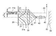
本発明の他の実施形態に係るレーザ装置について、図6を用いて説明する。本実施形態では、典型的なブロードエリアレーザダイオードのうちの1つと共に使用し得るファイバカップリングモジュールのための外形寸法例が提供される。 A laser apparatus according to another embodiment of the present invention will be described with reference to FIG. In this embodiment, example dimensions are provided for a fiber coupling module that can be used with one of the typical broad area laser diodes.
本実施形態によるレーザ装置は、ブロードエリア・ダイオードレーザ610(レーザ光源)、レーザ610から出射されたレーザビームの質を高めるための光学系620、アパーチャ21を備えたアイソレータ20、非球面レンズ30(光学素子)、および光ファイバ40を含んでいる。アイソレータ20および非球面レンズ30の機能は、本質的に、図1および図2で説明した上述の実施形態中のものと同じである。
The laser apparatus according to the present embodiment includes a broad area diode laser 610 (laser light source), an
本実施形態において、ブロードエリア・ダイオードレーザ610は、100×1μmのストライプ長および808nmの波長を有する。ブロードエリア・ダイオードレーザ610から出射されたレーザビームは、図6で示されるような遅軸および速軸を有する。光学系620は、ストライプ長100μmおよび波長808nmのレーザビーム用に構成されており、ビームの発散角(divergence)が遅軸で0.46°、速軸で24°の高品質のレーザビームを出射する。光ファイバ40は、ステップ型の一種で直径200μmおよび開口数0.22である。
In this embodiment, the broad
図6で示されるレーザ装置では、以下の寸法を用いることによって、光学系620とブロードエリア・ダイオードレーザ610に向けて反射される出力の比率「Pf」を許容可能なレベル(多くの場合は5〜10%である)まで減少させる可能性がある:
Z1: 〜4mm
Z2: 〜8mm
Z3:〜16mm
d: 3mm
アパーチャ21(クリアアパーチャ):〜0.2mm(遅軸)×〜1.8mm(速軸)
非球面レンズ30: 有効焦点距離8mm、アパーチャ8mm
ここで、Z1は光学系620の出射表面からアイソレータ20までの距離;Z2は光学系620の出射表面から非球面レンズ30までの距離;Z3は非球面レンズ30から光ファイバ40の入口端面までの距離;およびdはアパーチャ21の中心軸と光ファイバ40の中心軸の間の距離である。
In the laser apparatus shown in FIG. 6, the ratio “Pf” of the output reflected toward the
Z1: ~ 4mm
Z2: ~ 8mm
Z3: ~ 16mm
d: 3 mm
Aperture 21 (clear aperture): ~ 0.2mm (slow axis) x ~ 1.8mm (fast axis)
Aspheric lens 30: Effective focal length 8mm, aperture 8mm
Here, Z1 is the distance from the exit surface of the
本実施形態によれば、所望のレーザ光源および光ファイバのセットにおいて、レーザ光源に達するフィードバック注入を望ましいレベルへ削減することができる。削減量は、受容可能なフィードバック注入の最大のレベル等のシステム仕様に応じて決定できる。 According to the present embodiment, in a desired laser light source and optical fiber set, feedback injection reaching the laser light source can be reduced to a desired level. The amount of reduction can be determined according to system specifications such as the maximum level of feedback injection that can be accepted.
なお、添付の特許請求の範囲またはそれと均等な範囲の限りにおいて、設計条件およびその他の要因に応じて、様々な変更、組合せ、副次的組合せおよび修正が生じ得ることは、当業者によって理解されることである。 It should be understood by those skilled in the art that various changes, combinations, sub-combinations, and modifications can occur depending on design conditions and other factors within the scope of the appended claims or equivalents thereof. Is Rukoto.
10:レーザダイオード、20:アイソレータ、21:アパーチャ、22:アパーチャの中心軸、30:フォーカスレンズ、40:光ファイバ、41:光ファイバの入口、42:光ファイバの出口、50:目標材、51:目標材の表面。
10: Laser diode, 20: Isolator, 21: Aperture, 22: Center axis of aperture, 30: Focus lens, 40: Optical fiber, 41: Inlet of optical fiber, 42: Outlet of optical fiber, 50: Target material, 51 : Surface of target material.
Claims (15)
前記レーザ光源と前記光ファイバとの間に配置され、前記レーザ光源からのレーザ光線を通過させる開口を有するアイソレータと、
前記アイソレータと前記光ファイバとの間に配置され、前記開口を通過したレーザ光線を前記光ファイバへ導く光学素子とを備え、
前記レーザ光線による処理の対象物の表面で反射され、前記光ファイバ及び前記光学素子を通して前記アイソレータに入射した光が主要部分となるフィードバック光の一部が前記アイソレータにより遮蔽されるように、前記アイソレータの開口と前記光ファイバとがずれて配置されている
ファイバカップリングモジュール。 Upon the laser beam emitted from the laser light source is incident on the surface of the object of processing by the laser beam through an optical fiber, fiber coupling for coupling to the optical fiber the laser beam emitted from the laser light source A module ,
An isolator disposed between the laser light source and the optical fiber and having an aperture through which a laser beam from the laser light source passes;
An optical element that is disposed between the isolator and the optical fiber and guides the laser beam that has passed through the opening to the optical fiber;
The isolator is shielded by the isolator so that a part of the feedback light which is reflected by the surface of the object to be processed by the laser beam and becomes the main part through the optical fiber and the optical element is incident on the isolator. that are staggered opening and said optical fiber
Off § driver coupling module.
前記対象物へ前記レーザ光線を送るための光ファイバとをさらに具備する請求項1記載のファイバカップリングモジュール。 A laser light source for generating the laser beam;
Further fiber coupling module 請 Motomeko 1, wherein you and a optical fiber for transmitting the laser beam to the object.
前記ファイバカップリングモジュールは、
前記レーザ光源と前記光ファイバとの間に配置され、前記レーザ光源からのレーザ光線を通過させる開口を有するアイソレータと、
前記アイソレータと前記光ファイバとの間に配置され、前記開口を通過したレーザ光線を前記光ファイバへ導く光学素子とを備え、
前記レーザ光線による処理の対象物の表面で反射され、前記光ファイバ及び前記光学素子を通して前記アイソレータに入射した光が主要部分となるフィードバック光の一部が前記アイソレータにより遮蔽されるように、前記アイソレータの開口と前記光ファイバとがずれて配置されている
レーザ装置。 Upon the laser beam emitted from the laser light source is incident on the surface of the object of processing by the laser beam through an optical fiber, fiber coupling for coupling to the optical fiber the laser beam emitted from the laser light source In a laser device including a module,
The fiber coupling module is:
An isolator disposed between the laser light source and the optical fiber and having an aperture through which a laser beam from the laser light source passes;
An optical element that is disposed between the isolator and the optical fiber and guides the laser beam that has passed through the opening to the optical fiber;
The isolator is shielded by the isolator so that a part of the feedback light which is reflected by the surface of the object to be processed by the laser beam and becomes the main part through the optical fiber and the optical element is incident on the isolator. that are staggered opening and said optical fiber
Les over laser device.
Priority Applications (2)
| Application Number | Priority Date | Filing Date | Title |
|---|---|---|---|
| JP2005121255A JP4544014B2 (en) | 2005-04-19 | 2005-04-19 | Laser device and fiber coupling module |
| US11/629,458 US20080203838A1 (en) | 2004-10-07 | 2005-09-14 | Dynamic Bearing Device |
Applications Claiming Priority (1)
| Application Number | Priority Date | Filing Date | Title |
|---|---|---|---|
| JP2005121255A JP4544014B2 (en) | 2005-04-19 | 2005-04-19 | Laser device and fiber coupling module |
Publications (2)
| Publication Number | Publication Date |
|---|---|
| JP2006301195A JP2006301195A (en) | 2006-11-02 |
| JP4544014B2 true JP4544014B2 (en) | 2010-09-15 |
Family
ID=37469568
Family Applications (1)
| Application Number | Title | Priority Date | Filing Date |
|---|---|---|---|
| JP2005121255A Expired - Fee Related JP4544014B2 (en) | 2004-10-07 | 2005-04-19 | Laser device and fiber coupling module |
Country Status (1)
| Country | Link |
|---|---|
| JP (1) | JP4544014B2 (en) |
Families Citing this family (5)
| Publication number | Priority date | Publication date | Assignee | Title |
|---|---|---|---|---|
| US8007401B2 (en) | 2007-05-02 | 2011-08-30 | Nissan Motor Co., Ltd. | Hybrid vehicle drive control apparatus and method |
| JP7461870B2 (en) * | 2018-02-14 | 2024-04-04 | 古河電気工業株式会社 | Semiconductor Laser Module |
| JP7154057B2 (en) * | 2018-07-26 | 2022-10-17 | 京セラSoc株式会社 | semiconductor laser module |
| JP7141972B2 (en) * | 2019-03-20 | 2022-09-26 | 京セラSoc株式会社 | Semiconductor laser light source |
| CN113376766A (en) * | 2021-05-21 | 2021-09-10 | 中国人民解放军战略支援部队航天工程大学 | Light path beam combining and optical fiber coupling device of space light laser |
Citations (10)
| Publication number | Priority date | Publication date | Assignee | Title |
|---|---|---|---|---|
| JPH04238308A (en) * | 1991-01-22 | 1992-08-26 | Mitsubishi Electric Corp | Semiconductor laser device |
| JPH05288966A (en) * | 1992-04-13 | 1993-11-05 | Sumitomo Electric Ind Ltd | Light emitting element |
| JPH07281062A (en) * | 1994-04-12 | 1995-10-27 | Nippon Sheet Glass Co Ltd | Semiconductor laser module |
| JPH0980274A (en) * | 1995-09-14 | 1997-03-28 | Nec Corp | Semiconductor laser module |
| JPH09211268A (en) * | 1996-02-05 | 1997-08-15 | Alps Electric Co Ltd | Light emission module |
| JPH10135571A (en) * | 1996-10-25 | 1998-05-22 | Hitachi Metals Ltd | Optical condensing system of semiconductor laser |
| JP2000310746A (en) * | 1999-04-27 | 2000-11-07 | Fuji Photo Film Co Ltd | Image recording device and optical fiber |
| JP2001188149A (en) * | 1999-12-28 | 2001-07-10 | Sharp Corp | Bi-directional optical communicator and bi-directional optical communicating device |
| JP2001194560A (en) * | 2000-01-13 | 2001-07-19 | Sharp Corp | Bi-directional optical communication device and bi- directional optical communication equipment |
| JP2002243987A (en) * | 2001-02-13 | 2002-08-28 | Sony Corp | Optical coupling device |
-
2005
- 2005-04-19 JP JP2005121255A patent/JP4544014B2/en not_active Expired - Fee Related
Patent Citations (10)
| Publication number | Priority date | Publication date | Assignee | Title |
|---|---|---|---|---|
| JPH04238308A (en) * | 1991-01-22 | 1992-08-26 | Mitsubishi Electric Corp | Semiconductor laser device |
| JPH05288966A (en) * | 1992-04-13 | 1993-11-05 | Sumitomo Electric Ind Ltd | Light emitting element |
| JPH07281062A (en) * | 1994-04-12 | 1995-10-27 | Nippon Sheet Glass Co Ltd | Semiconductor laser module |
| JPH0980274A (en) * | 1995-09-14 | 1997-03-28 | Nec Corp | Semiconductor laser module |
| JPH09211268A (en) * | 1996-02-05 | 1997-08-15 | Alps Electric Co Ltd | Light emission module |
| JPH10135571A (en) * | 1996-10-25 | 1998-05-22 | Hitachi Metals Ltd | Optical condensing system of semiconductor laser |
| JP2000310746A (en) * | 1999-04-27 | 2000-11-07 | Fuji Photo Film Co Ltd | Image recording device and optical fiber |
| JP2001188149A (en) * | 1999-12-28 | 2001-07-10 | Sharp Corp | Bi-directional optical communicator and bi-directional optical communicating device |
| JP2001194560A (en) * | 2000-01-13 | 2001-07-19 | Sharp Corp | Bi-directional optical communication device and bi- directional optical communication equipment |
| JP2002243987A (en) * | 2001-02-13 | 2002-08-28 | Sony Corp | Optical coupling device |
Also Published As
| Publication number | Publication date |
|---|---|
| JP2006301195A (en) | 2006-11-02 |
Similar Documents
| Publication | Publication Date | Title |
|---|---|---|
| US9268142B2 (en) | Optical cross-coupling mitigation system for multi-wavelength beam combining systems | |
| JP3589299B2 (en) | Beam shaping device | |
| JP3098200B2 (en) | Laser beam correction method and apparatus | |
| US10871639B2 (en) | Optical cross-coupling mitigation systems for wavelength beam combining laser systems | |
| JP4544014B2 (en) | Laser device and fiber coupling module | |
| CA2329089C (en) | Fiber grating feedback stabilization of broad area laser diode | |
| JP2005537643A (en) | Semiconductor laser device | |
| US7251260B2 (en) | Wavelength-locked fiber-coupled diode-laser bar | |
| US7251259B2 (en) | Wavelength locked fiber-coupled diode-laser bar | |
| US11287574B2 (en) | Optical fiber bundle with beam overlapping mechanism | |
| US6529657B2 (en) | Angle selective side-pumping of fiber amplifiers and lasers | |
| US11757258B2 (en) | Light source device and direct diode laser system | |
| US7376168B2 (en) | Semiconductor laser device | |
| KR102271640B1 (en) | Optical fiber laser assembly | |
| WO2020202757A1 (en) | Laser module and fiber laser device | |
| WO1998015994A1 (en) | External cavity micro laser apparatus | |
| WO2006104034A1 (en) | External resonance type semiconductor laser | |
| US6563983B2 (en) | Laser diode module | |
| US20240113488A1 (en) | Suppression of undesired wavelengths in laser light | |
| JP2000284133A (en) | Optical fiber and semiconductor laser module | |
| US20060104329A1 (en) | Apparatus for diode laser beam quality control | |
| JP2023044115A (en) | laser device | |
| JP2020120000A (en) | Light source unit | |
| JP2004341057A (en) | Beam shaping device | |
| JPH0774417A (en) | Solid-state laser device using optical fiber |
Legal Events
| Date | Code | Title | Description |
|---|---|---|---|
| RD03 | Notification of appointment of power of attorney |
Free format text: JAPANESE INTERMEDIATE CODE: A7423 Effective date: 20060808 |
|
| A621 | Written request for application examination |
Free format text: JAPANESE INTERMEDIATE CODE: A621 Effective date: 20080313 |
|
| A977 | Report on retrieval |
Free format text: JAPANESE INTERMEDIATE CODE: A971007 Effective date: 20100202 |
|
| A131 | Notification of reasons for refusal |
Free format text: JAPANESE INTERMEDIATE CODE: A131 Effective date: 20100330 |
|
| A521 | Written amendment |
Free format text: JAPANESE INTERMEDIATE CODE: A523 Effective date: 20100524 |
|
| TRDD | Decision of grant or rejection written | ||
| A01 | Written decision to grant a patent or to grant a registration (utility model) |
Free format text: JAPANESE INTERMEDIATE CODE: A01 Effective date: 20100608 |
|
| A01 | Written decision to grant a patent or to grant a registration (utility model) |
Free format text: JAPANESE INTERMEDIATE CODE: A01 |
|
| A61 | First payment of annual fees (during grant procedure) |
Free format text: JAPANESE INTERMEDIATE CODE: A61 Effective date: 20100621 |
|
| FPAY | Renewal fee payment (event date is renewal date of database) |
Free format text: PAYMENT UNTIL: 20130709 Year of fee payment: 3 |
|
| FPAY | Renewal fee payment (event date is renewal date of database) |
Free format text: PAYMENT UNTIL: 20130709 Year of fee payment: 3 |
|
| LAPS | Cancellation because of no payment of annual fees |