JP4541757B2 - Polarizing element - Google Patents
Polarizing element Download PDFInfo
- Publication number
- JP4541757B2 JP4541757B2 JP2004149224A JP2004149224A JP4541757B2 JP 4541757 B2 JP4541757 B2 JP 4541757B2 JP 2004149224 A JP2004149224 A JP 2004149224A JP 2004149224 A JP2004149224 A JP 2004149224A JP 4541757 B2 JP4541757 B2 JP 4541757B2
- Authority
- JP
- Japan
- Prior art keywords
- period
- incident
- light beam
- polarizing element
- layer
- Prior art date
- Legal status (The legal status is an assumption and is not a legal conclusion. Google has not performed a legal analysis and makes no representation as to the accuracy of the status listed.)
- Expired - Fee Related
Links
Images


Description
本発明は、複数の波長、あるいは帯域光で、かつ、比較的広い入射角度範囲で使用する偏光分離素子などの偏光素子に関し、例えば、撮影光学系、投写型表示装置(プロジェクタ)、画像処理装置、半導体製造装置、等の各種光学機器に関するものである。 The present invention relates to a polarization element such as a polarization separation element that has a plurality of wavelengths or band lights and is used in a relatively wide incident angle range. For example, the present invention relates to a photographing optical system, a projection display device (projector), and an image processing device. The present invention relates to various optical devices such as semiconductor manufacturing apparatuses.
従来より、波長以下の周期の一次元格子形状を持つSWS(sub−wavelength structure)素子が構造複屈折性を有する事は知られてる。 Conventionally, it has been known that a SWS (sub-wavelength structure) element having a one-dimensional grating shape with a period equal to or less than a wavelength has a structural birefringence.
一般的に図24に示すような一次元格子においてn1、n2の媒質がa:bの比で繰り返す一次元格子でそれぞれの偏光の有効屈折率は式(1)(2)で表される。 In general, in a one-dimensional grating as shown in FIG. 24, a medium of n 1 and n 2 repeats at a ratio of a: b, and the effective refractive index of each polarized light is expressed by equations (1) and (2). The

1次元格子においてn1を誘電体、n2を空気としたとき、媒質のピッチに対する比率であるフィリングファクターfは式(3)で示される。この例ではフィリングファクターを約0.5程度になるようにエッチングしたものである。
f=a/(a+b) ・・・(3)
図25は、一次元格子の誘電体をTiO2(n1=2.304)を、一方を空気(n2=1.0)とした格子でのTiO2のフィリングファクタfに対する有効屈折率の変化を表したグラフである。
In a one-dimensional lattice, when n1 is a dielectric and n2 is air, a filling factor f, which is a ratio to the pitch of the medium, is expressed by Equation (3). In this example, the etching is performed so that the filling factor is about 0.5.
f = a / (a + b) (3)
FIG. 25 shows a change in effective refractive index with respect to the filling factor f of TiO2 in a lattice in which the dielectric of a one-dimensional lattice is TiO2 (n1 = 2.304) and one is air (n2 = 1.0). It is a graph.
図25よりfの値によらずnTE>nTMである。 From FIG. 25, n TE > n TM regardless of the value of f.
上記のような一次元格子が有効屈折率で記述できる条件としては、格子のピッチが十分に小さく、回折が起こらないことが必要である。 As a condition that the one-dimensional grating as described above can be described by an effective refractive index, it is necessary that the pitch of the grating is sufficiently small so that diffraction does not occur.
図3に示すようなピッチdの格子の入射側媒質の屈折率をn1、射出側媒質の屈折率をn2とし、入射光の入射角をθ1、回折による射出光の射出角をθ2とすると、隣あう、光線の光路差(L1−L2)が波長の整数倍となるとき回折光が発生する。これは条件式(4)で表われ、この式が成り立つときに回折が発生する。
dn1sinθ1−dn2sinθ2=mλ ・・・(4)
ただし、mは整数
この式(4)がm=0以外に解が存在しないようにすれば回折が生じない。
When the refractive index of the incident-side medium of the grating having the pitch d as shown in FIG. 3 is n1, the refractive index of the emission-side medium is n2, the incident angle of incident light is θ1, and the exit angle of emitted light by diffraction is θ2. When the adjacent optical path difference (L1-L2) is an integral multiple of the wavelength, diffracted light is generated. This is expressed by conditional expression (4), and diffraction occurs when this expression holds.
dn1sin θ1-dn2sin θ2 = mλ (4)
However, m is an integer. If this equation (4) is set so that there is no solution other than m = 0, diffraction does not occur.
入射側、射出側の媒質をともにnとして、式(4)を式(5)のように変形する。
sinθ1−sinθ2=mλ/dn ・・・(5)
θ1、θ2が任意の値をとると考えると、式(5)の左辺は式(6)の範囲となる。
−2 ≦ 左辺 ≦ 2 ・・・(6)
よって、λ/dnが左辺より大きければ回折は生じない。すなわち、式(7)が全ての入射角で回折を生じさせないための条件となる。
d < λ /2n ・・・(7)
この一次元格子を互いに直交する様に積層したいわゆる井桁構造の素子に関して製法が特許文献1に提案されている。周期的に積層された感光特性のことなる感光材料を積層構造に配置し、それぞれを感光、エッチングすることで井桁構造を実現している。実施例としては井桁構造の模式図だけであり、具体的な形状の大きさを示す数値実施例の記載はないが、フォトニック結晶として使用するには格子のピッチが波長以下である必要があり、また上記の回折の生じない条件を満たさなければならない。素子の入射側、射出側の媒質は空気(n=1.0)であり条件式(7)より波長の半分程度のピッチで構成されていると考えられる。
sin θ1−sin θ2 = mλ / dn (5)
Assuming that θ1 and θ2 take arbitrary values, the left side of equation (5) is in the range of equation (6).
-2 ≤ left side ≤ 2 (6)
Therefore, if λ / dn is larger than the left side, diffraction does not occur. That is, Equation (7) is a condition for preventing diffraction from occurring at all incident angles.
d <λ / 2n (7)
A manufacturing method is proposed in
しかしながら、上記の素子を偏光分離素子などの様に2つのプリズムの間に埋め込んだ構成で使用する際には、上記条件式(7)において屈折率nが空気に比べて大きくなる分、回折を生じさせないためのピッチが狭くなる。上記のような一次元格子では、ピッチに占める媒質の比(フィリングファクタ)と格子の厚み(h)とを変えずにピッチを狭めると、格子の高さと幅の比(アスペクト比)が大きくなることになり、製造上の難易度が増すと言う問題があった。 However, when the above element is used in a configuration in which it is embedded between two prisms, such as a polarization separation element, diffraction is caused by the fact that the refractive index n in the conditional expression (7) is larger than that of air. The pitch for preventing it from becoming narrower. In the one-dimensional grating as described above, if the pitch is narrowed without changing the ratio of the medium to the pitch (filling factor) and the thickness (h) of the grating, the ratio of the height and width of the grating (aspect ratio) increases. As a result, there was a problem that the manufacturing difficulty level increased.
本発明は、これらの問題を鑑み、使用する光束の入射角度と方向に応じてピッチを最適に設定することで、全光束に対して回折が発生しない条件を保ちながらも、製造が簡易となる構成の偏光素子を得ることを目的とする。 In view of these problems, the present invention sets the pitch optimally according to the incident angle and direction of the light beam to be used, thereby simplifying the manufacturing while maintaining the condition that no diffraction occurs with respect to the total light beam. It is an object to obtain a polarizing element having a configuration.
上記の問題を解決するために、本発明は、所定面と平行な第1の周期方向において使用波長以下の周期の屈折率周期構造を持つ層と、前記所定面と平行で前記第1の周期方向と垂直な第2の周期方向において使用波長以下の周期の屈折率周期構造を持つ層とが前記所定面と垂直な方向に積層されている偏光分離層の両側をプリズムで挟み込んだ偏光素子であって、
前記プリズムの光弾性定数の絶対値が1.0×10⁻⁸cm2/Nより小さく、前記2つのプリズムのうち入射側プリズムの入射面に対して、前記偏光分離層は45°傾いており、前記第1の周期方向及び前記第2の周期方向のうち、前記偏光素子に入射する光束のうち入射角度が最大となる光線の入射平面に対して平行に近い周期方向における周期をPA、それと直交する周期方向における周期をPBとするとき、以下の条件式を満たす事を特徴とする偏光素子とした。
PA<PB
In order to solve the above problem, the present invention provides a layer having a refractive index periodic structure having a period equal to or shorter than a use wavelength in a first periodic direction parallel to a predetermined surface, and the first periodic in parallel to the predetermined surface. A polarizing element in which both sides of a polarization separation layer in which a layer having a refractive index periodic structure with a period equal to or shorter than a use wavelength in a second periodic direction perpendicular to the direction is laminated in a direction perpendicular to the predetermined plane are sandwiched by prisms There,
The absolute value of the photoelastic constant of the prism is smaller than 1.0 × 10 −8 cm 2 / N, and the polarization separation layer is inclined by 45 ° with respect to the incident surface of the incident side prism of the two prisms, Of the first periodic direction and the second periodic direction, the period in the periodic direction that is nearly parallel to the incident plane of the light beam having the maximum incident angle among the light beams incident on the polarizing element is PA, and is orthogonal thereto. When the period in the period direction is PB, the polarizing element is characterized by satisfying the following conditional expression.
PA <PB
本発明は、所定面と平行な第1の周期方向において使用波長以下の周期の屈折率周期構造を持つ層と、前記所定面と平行で前記第1の周期方向と垂直な第2の周期方向において使用波長以下の周期の屈折率周期構造を持つ層とが前記所定面と垂直な方向に積層されている偏光分離層の両側をプリズムで挟み込んだ偏光素子であって、
前記プリズムの光弾性定数の絶対値が1.0×10⁻⁸cm2/Nより小さく、前記2つのプリズムのうち入射側プリズムの入射面に対して、前記偏光分離層は45°傾いており、前記偏光素子に入射する光束のうち光束の中心光線を代表光線とするとき、前記第1の周期方向及び前記第2の周期方向のうち、前記代表光線が前記偏光素子に入射するときの入射平面に対して平行に近い周期方向における周期をPA、それと直交する周期方向における周期をPBとするとき、以下の条件式を満たす事を特徴とする偏光素子とした。
PA<PB
The present invention includes a layer having a refractive index periodic structure having a period equal to or shorter than a use wavelength in a first periodic direction parallel to a predetermined surface, and a second periodic direction parallel to the predetermined surface and perpendicular to the first periodic direction. A polarizing element in which a layer having a refractive index periodic structure with a period equal to or shorter than the used wavelength is sandwiched between prisms on both sides of the polarization separation layer laminated in a direction perpendicular to the predetermined plane,
The absolute value of the photoelastic constant of the prism is smaller than 1.0 × 10 −8 cm 2 / N, and the polarization separation layer is inclined by 45 ° with respect to the incident surface of the incident side prism of the two prisms, When the central light beam of the light beam incident on the polarizing element is a representative light beam, the light beam is incident on the incident plane of the first periodic direction and the second periodic direction when the representative light beam is incident on the polarizing element. On the other hand, a polarizing element is characterized in that the following conditional expression is satisfied, where PA is a period in a periodic direction that is nearly parallel, and PB is a period in a periodic direction that is orthogonal thereto.
PA <PB
本発明は、所定面と平行な第1の周期方向において使用波長以下の周期の屈折率周期構造を持つ層と、前記所定面と平行で前記第1の周期方向と垂直な第2の周期方向において使用波長以下の周期の屈折率周期構造を持つ層とが前記所定面と垂直な方向に積層されている偏光分離層の両側をプリズムで挟み込んだ偏光素子であって、
前記プリズムは光弾性定数の絶対値が1.0×10⁻⁸cm2/Nより小さく、前記2つのプリズムのうち入射側プリズムの入射面に対して、前記偏光分離層は45°傾いており、前記偏光素子から射出する光束のうち射出側に置かれた前記2つのプリズムのうち射出側プリズムの光軸を通る光線を代表光線とするとき、前記第1の周期方向及び前記第2の周期方向のうち、前記代表光線が前記偏光素子に入射するときの入射平面に対して平行に近い周期方向における周期をPA、それと直交する周期方向における周期をPBとするとき、以下の条件式を満たす事を特徴とする偏光素子とした。
PA<PB
The present invention includes a layer having a refractive index periodic structure having a period equal to or shorter than a use wavelength in a first periodic direction parallel to a predetermined surface, and a second periodic direction parallel to the predetermined surface and perpendicular to the first periodic direction. A polarizing element in which a layer having a refractive index periodic structure with a period equal to or shorter than the used wavelength is sandwiched between prisms on both sides of the polarization separation layer laminated in a direction perpendicular to the predetermined plane,
The prism has an absolute value of a photoelastic constant smaller than 1.0 × 10 −8 cm 2 / N, and the polarization separation layer is inclined by 45 ° with respect to the incident surface of the incident side prism of the two prisms, When the light beam passing through the optical axis of the exit side prism among the two prisms placed on the exit side of the light beam exiting from the polarizing element is used as a representative light beam, the first periodic direction and the second periodic direction Among them, when the period in the periodic direction that is nearly parallel to the incident plane when the representative light beam is incident on the polarizing element is PA and the period in the periodic direction perpendicular to the same is PB, the following conditional expression must be satisfied. It was set as the characteristic polarizing element.
PA <PB
上記の偏光素子を用いて、光源部からの光束を画像信号に基づいて変調する変調手段に導光し、該変調手段により変調された光束を投写光学系によって所定面上に投写していることで有効な投写型表示装置が得られる。 Using the polarizing element, the light beam from the light source unit is guided to a modulation unit that modulates based on an image signal, and the light beam modulated by the modulation unit is projected onto a predetermined surface by a projection optical system. Thus, an effective projection display device can be obtained.
本発明によれば、前述のように、偏光素子をプリズムに挟んだ構造に関して、製造上簡易な形状をであり、偏光素子性能も、波長特性、入射角度特性ともに広い範囲で高い性能を持った偏光素子素子を実現することができるという効果がある。 According to the present invention, as described above, the structure in which the polarizing element is sandwiched between the prisms has a simple shape in manufacture, and the polarizing element performance has high performance in a wide range in both wavelength characteristics and incident angle characteristics. There is an effect that a polarizing element can be realized.
図1は本発明の実施例1の偏光分離プリズムの構成図である。表1に実施例1の構成をあらわす設計値を示す。 FIG. 1 is a configuration diagram of a polarization splitting prism according to a first embodiment of the present invention. Table 1 shows design values representing the configuration of the first embodiment.
図1において、プリズムの入射面(25)に対して、偏光分離層(23)は45°傾いている。入射面(25)に垂直に入射する光線のP偏光(18)、S偏光(20)が偏光分離層(23)に入射し、S偏光は反射(21)させ、図1の入射側プリズム(22)にある入射面(25)とは別の射出面(26)から射出させる。また、P偏光は透過(19)させ、射出側プリズム(24)にある射出面(27)から射出させる構成となっている。 In FIG. 1, the polarization separation layer (23) is inclined 45 ° with respect to the incident surface (25) of the prism. P-polarized light (18) and S-polarized light (20) incident on the incident surface (25) perpendicularly enter the polarization separation layer (23), and reflect (21) the S-polarized light. The light is emitted from an exit surface (26) different from the entrance surface (25) in 22). The P-polarized light is transmitted (19) and is emitted from the exit surface (27) on the exit-side prism (24).
図2に格子の方向を表す模式図を示す。偏光分離層(23)に入射する際の入射平面(28)と偏光分離層の第1の一次元格子は図2のように平行となり、その方向を格子方向Pとする。第2の一次元格子は図2のように入射平面と直交する配置であり、その方向は格子方向Vとする。 FIG. 2 is a schematic diagram showing the direction of the lattice. The incident plane (28) when entering the polarization separation layer (23) and the first one-dimensional grating of the polarization separation layer are parallel to each other as shown in FIG. The second one-dimensional grating is arranged perpendicular to the incident plane as shown in FIG.
図4は格子を斜めから見た図であり、図5は図2の29の矢印で示す方向Aから見た格子の断面構造図であり、図6は図2の30の矢印で示す方向Bから見た格子の断面構造図である。第1の一次元格子は空気と誘電体が交互に繰り返す格子方向PのL層(101,103)である、第2の一次元格子は空気と誘電体が交互に繰り返す格子方向VのH層(102)より構成されている。全体で3層と言う比較的簡易な構成で偏光分離を実現することが可能である。また、誘電体としてはTiO2を用いている。
4 is a view of the lattice obliquely, FIG. 5 is a cross-sectional structural view of the lattice viewed from the direction A indicated by the arrow 29 in FIG. 2, and FIG. 6 is a direction B indicated by the
それぞれの層をH層、L層としているのは、反射させるS偏光に対してのそれぞれの有効屈折率の高低を表している。格子方向Vの一次元格子層の厚さは64nmであり、S偏光の反射を完全に達成するのに十分な厚さとなっている。一般的に高屈折率の媒質から低屈折率の媒質に入射するときに入射角度が臨界角以上では、一切透過せずに全反射することが知られている。しかし、この時に、境界面近傍の極めて微小な領域において、エバネセント光がしみ出ている。この光の到達領域に次の媒質があると光が透過してしまう。この現象が全反射減衰(attenuated total reflection:ATR)である。このATRの光同士の干渉を利用して広い角度範囲、波長範囲で高い反射率を得るのである。一方、格子方向Pの一次元格子のからなるL層の厚さは370nmであり、この数字はATRによる反射を有効に活用するためのものである。 The reason why the layers are the H layer and the L layer represents the level of the effective refractive index with respect to the S-polarized light to be reflected. The thickness of the one-dimensional grating layer in the grating direction V is 64 nm, which is sufficient to completely achieve S-polarized light reflection. In general, it is known that when a light is incident on a medium having a low refractive index from a medium having a high refractive index, if the incident angle is equal to or greater than a critical angle, the light is totally transmitted without being transmitted. However, at this time, evanescent light oozes out in a very small region near the boundary surface. If there is a next medium in the light arrival region, the light is transmitted. This phenomenon is attenuated total reflection (ATR). By utilizing the interference between the light beams of the ATR, a high reflectance is obtained in a wide angle range and wavelength range. On the other hand, the thickness of the L layer made of a one-dimensional grating in the grating direction P is 370 nm, and this number is for effectively utilizing reflection by ATR.
この膜厚が薄くなると、臨界角以上の入射角度領域ではATRによる透過が大きくなり、十分な反射が得られない。 When this film thickness is reduced, transmission by ATR increases in the incident angle region above the critical angle, and sufficient reflection cannot be obtained.
一方、ATRの観点からは、膜厚が厚ければ厚いほど好ましい。しかしながら、膜厚を増しても、反射率は全反射に漸近してしまうため、膜厚を増やしただけの効果は得られない。この一次元格子の形状では、膜厚を増すほど製造の難易度は上がる。そのため、実施例の厚み程度に設定することが好ましい。 On the other hand, from the viewpoint of ATR, the thicker the film thickness, the better. However, even if the film thickness is increased, the reflectance becomes asymptotic to total reflection, so that the effect of simply increasing the film thickness cannot be obtained. With this one-dimensional lattice shape, the manufacturing difficulty increases as the film thickness increases. For this reason, it is preferable to set the thickness to about the thickness of the embodiment.
また、使用角度の範囲に臨界角以下の通常反射を含むが、そこでの干渉においては実施例での厚みに設定することで、最適な結果が得られた。 Further, the range of the use angle includes normal reflection below the critical angle, but in the interference there, the optimum result was obtained by setting the thickness in the example.
実施例1では表1に設計値を示すとおり、プリズムの硝材に屈折率が約1.603と比較的低い物を使用した。格子方向Vの一次元格子であるH層と、格子方向Pの一次元格子であるL層の誘電体はともにTiO2であり、屈折率2.282の高屈折率な物を使用し、フィリングファクタをL層=0.18、H層=0.84に設定することで、効率よく複屈折を生じさせている。 In Example 1, as shown in Table 1, a relatively low refractive index of about 1.603 was used for the glass material of the prism. The dielectrics of the H layer, which is a one-dimensional lattice in the lattice direction V, and the L layer, which is a one-dimensional lattice in the lattice direction P, are both TiO 2 , and a high refractive index material having a refractive index of 2.282 is used for filling. Birefringence is efficiently generated by setting the factors to L layer = 0.18 and H layer = 0.84.
格子方向Vの一次元格子の層に関しては、P偏光がTM、S偏光がTEとなる。また、格子方向Pの一次元格子の層に関しては、P偏光がTE、S偏光がTMとなる。 Regarding the layer of the one-dimensional grating in the grating direction V, the P-polarized light is TM and the S-polarized light is TE. For the one-dimensional lattice layer in the lattice direction P, P-polarized light is TE and S-polarized light is TM.
(1)、(2)の式において、一方の媒質をTiO2、他方を空気として、フィリングファクタf(ピッチに対するTiO2の割合)を変化させたときのそれぞれの偏光に対する有効屈折率を表すグラフは図25の様になる。 In the expressions (1) and (2), a graph showing effective refractive indexes for respective polarized light when one medium is TiO 2 and the other is air and the filling factor f (the ratio of TiO 2 to the pitch) is changed. Is as shown in FIG.
P偏光に関して、表1に示すとおり第1の一次元格子がf=0.18の時、TE方向の有効屈折率は1.35となり、第2の一次元格子ではf=0.84の時、TM方向の有効屈折率は1.83となる。 For P-polarized light, as shown in Table 1, when the first one-dimensional grating is f = 0.18, the effective refractive index in the TE direction is 1.35, and for the second one-dimensional grating, f = 0.84. The effective refractive index in the TM direction is 1.83.
一方のS偏光に関して、表1に示すとおり第1の一次元格子ではTM方向の有効屈折率は1.07となり、第2の一次元格子ではTE方向の有効屈折率は2.18となる。 For one S-polarized light, the effective refractive index in the TM direction is 1.07 in the first one-dimensional grating as shown in Table 1, and the effective refractive index in the TE direction is 2.18 in the second one-dimensional grating.
このように、第1と第2の1次元格子層との有効屈折率がP偏光に関しては近い値となり、S偏光に関しては大きな屈折率差を生じさせることで、それぞれの偏光の光線の透過、反射を実現している。 Thus, the effective refractive indexes of the first and second one-dimensional grating layers are close to each other with respect to the P-polarized light, and a large refractive index difference is generated with respect to the S-polarized light. Reflection is realized.
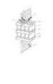
プリズム形状を図10に示す。入射側プリズム(22)と射出側プリズム(24)の間にL層格子(101,103)が図10に示す様に斜面方向に、H層格子(102)がそれと直交する方向で挟んだ形状である。 The prism shape is shown in FIG. A shape in which the L-layer grating (101, 103) is sandwiched between the incident-side prism (22) and the emission-side prism (24) in the inclined direction as shown in FIG. It is.
図11に入射光束を示す。このプリズムに入射光は図11の様に偏光素子面に45°をなす光軸(32)を中心に円形の開口をもって約Fno.2.0光束(31)として入射する。その際、図13に示すようなP方向の格子の周期方向と光軸(32)を含む平面を断面(33)としたとき、断面(33)内での入射光束の角度は、図14で示され、光軸に対してθ3の幅をもつ。 FIG. 11 shows the incident light flux. As shown in FIG. 11, the light incident on this prism has a circular opening centered on the optical axis (32) that forms 45 ° on the surface of the polarizing element, and is approximately Fno. Incident as 2.0 luminous flux (31). In this case, when the plane including the periodic direction of the grating in the P direction and the optical axis (32) as shown in FIG. 13 is a cross section (33), the angle of the incident light beam in the cross section (33) is as shown in FIG. It has a width of θ3 with respect to the optical axis.
また、図15に示すようなV方向の格子の周期方向と光軸(32)を含む平面を断面(34)としたとき、断面(34)内での入射光束の角度は、図16で示されるように、光軸がθ0傾き、入射角度が最大となる光線の角度はθ3となる。 Further, when the plane including the periodic direction of the grating in the V direction and the optical axis (32) as shown in FIG. 15 is a cross section (34), the angle of the incident light beam in the cross section (34) is shown in FIG. As shown, the angle of the light beam with the optical axis tilted by θ0 and the maximum incident angle is θ3.
それぞれの断面における入射角度と、格子ピッチが回折を起こさないようにする必要がある。図14の断面では光軸の格子に対する入射角度θ0は0°であり、入射角が最大となる光線はFno2.0のθ3=約14.5°となる。 It is necessary to prevent the incidence angle in each cross section and the grating pitch from causing diffraction. In the cross section of FIG. 14, the incident angle θ0 with respect to the grating of the optical axis is 0 °, and the light beam with the maximum incident angle is θ3 = about 14.5 ° of Fno2.0.
ここで、前述の回折の条件式(5)において、
sinθ1−sinθ2=mλ/dn ・・・(5)
入射光の入射角θ1は以下の範囲(9)であり、sinθ1は以下の範囲(10)となる。
−14.5≦θ1≦14.5 ・・・(9)
−0.25≦sinθ1≦0.25 ・・・(10)
θ2が任意であるとき、式(6)の左辺の取りうる値は以下のようである。
−1.25≦左辺≦1.25 ・・・(11)
よって、以下の条件をみたすときに式(5)はm=0以外の解が存在しない。
1.25<λ/dn ・・・(12)
すなわち、格子のピッチdが以下の条件式(13)を満たすとき回折は生じない。
d<λ/1.25n ・・・(13)
使用波長のうち、最も短い波長λ=430nm、プリズムの屈折率n=1.603を代入すると以下のようになる。
d<215[nm] ・・・(14)
図14の断面図で示される格子ピッチ、すなわちL層の格子ピッチは表1に示すように200nmとして上記の条件をほぼ満たす値としている。
Here, in the above-mentioned diffraction conditional expression (5),
sin θ1−sin θ2 = mλ / dn (5)
The incident angle θ1 of the incident light is in the following range (9), and sin θ1 is in the following range (10).
−14.5 ≦ θ1 ≦ 14.5 (9)
−0.25 ≦ sin θ1 ≦ 0.25 (10)
When θ2 is arbitrary, possible values of the left side of Equation (6) are as follows.
−1.25 ≦ left side ≦ 1.25 (11)
Therefore, when the following condition is satisfied, Equation (5) has no solution other than m = 0.
1.25 <λ / dn (12)
That is, no diffraction occurs when the grating pitch d satisfies the following conditional expression (13).
d <λ / 1.25n (13)
Of the wavelengths used, the shortest wavelength λ = 430 nm and the refractive index n = 1.603 of the prism are substituted as follows.
d <215 [nm] (14)
The lattice pitch shown in the cross-sectional view of FIG. 14, that is, the lattice pitch of the L layer, is 200 nm as shown in Table 1, which is a value that substantially satisfies the above conditions.
一方、図16の断面では光軸の格子に対する入射角度はθ0=45°であり、入射角度が最大になる光線の角度はθ3=59.5°となる。式(5)を用いて上記と同様に扱えば、式(5)の左辺の取りうる値は式(15)の範囲であり、格子ピッチdが以下の条件式(16)を満たすとき回折は生じない。
−1.87≦左辺≦1.87 ・・・(15)
d<λ/1.87n ・・・(16)
使用波長のうち、最も短い波長λ=430nm、プリズムの屈折率n=1.603を代入すると以下のようになる。
d<143[nm] ・・・(17)
図16の断面図で示される格子ピッチ、すなわちH層の格子ピッチは表1に示すように140nmとして上記の条件をほぼ満たす値としている。
On the other hand, in the cross section of FIG. 16, the incident angle of the optical axis with respect to the grating is θ0 = 45 °, and the angle of the light beam with the maximum incident angle is θ3 = 59.5 °. Using the expression (5) in the same manner as described above, the value that can be taken by the left side of the expression (5) is in the range of the expression (15), and when the grating pitch d satisfies the following conditional expression (16), the diffraction is Does not occur.
-1.87 ≦ left side ≦ 1.87 (15)
d <λ / 1.87n (16)
Of the wavelengths used, the shortest wavelength λ = 430 nm and the refractive index n = 1.603 of the prism are substituted as follows.
d <143 [nm] (17)
The lattice pitch shown in the cross-sectional view of FIG. 16, that is, the lattice pitch of the H layer is 140 nm as shown in Table 1, which is a value that substantially satisfies the above conditions.
光軸の入射角度θ0に関しても、最大光線の入射角度θ3に関しても、最大となる方向は入射平面がV方向なため。L層格子(101,103)のピッチがPB、H層格子(102)のピッチがPAとなる。これは、表3に示すように条件式(8)を満たす値となっている。 Regarding the incident angle θ0 of the optical axis and the incident angle θ3 of the maximum light beam, the maximum direction is because the incident plane is the V direction. The pitch of the L layer lattice (101, 103) is PB, and the pitch of the H layer lattice (102) is PA. This is a value satisfying conditional expression (8) as shown in Table 3.
表1に示す様に、L層格子の方がピッチが大きくなっているが、L層格子では媒質の幅の割合が小さく、層が厚いので、アスペクト比(格子幅に対する格子厚さの比)大きくなっているが、ピッチを少しでも大きくすることでアスペクト比が減少し製造上の難易度が軽減している。 As shown in Table 1, the pitch of the L-layer grating is larger, but in the L-layer grating, the medium width ratio is small and the layer is thick, so the aspect ratio (ratio of the grating thickness to the grating width) Although it is larger, increasing the pitch as much as possible reduces the aspect ratio and reduces manufacturing difficulty.
図26の(a)〜(c)図がこの設計値の厳密結合波解析計算(Rigorous coupled−wave analysis:RCWA)による性能のシミュレーション結果である。P偏光では、高入射角で、透過率が落ちているが、実使用時の角度特性のウエートを考慮するとほとんど問題ないレベルである。 FIGS. 26A to 26C show the simulation results of the performance by the rigorous coupled-wave analysis (RCWA) of this design value. In the P-polarized light, the transmittance is lowered at a high incident angle, but it is at a level that causes almost no problem in consideration of the weight of the angle characteristics in actual use.
S偏光に関しては低入射角の短波長側で性能が劣化している以外は35〜55°と言うかなり広い入射角範囲で透過する光線がほとんど無く、完全な反射率を達成している。 With respect to S-polarized light, there is almost no light beam transmitted in a fairly wide incident angle range of 35 to 55 ° except that the performance is deteriorated on the short wavelength side with a low incident angle, and a complete reflectance is achieved.
図7に実施例2の偏光分離素子の構成を示す。図7は格子を斜めから見た図である。実施例1と同様に図2のような方向から見た断面図がそれぞれ図8と図9である。 FIG. 7 shows the configuration of the polarization separation element of the second embodiment. FIG. 7 is a view of the lattice as viewed obliquely. 8 and 9 are sectional views as seen from the direction as shown in FIG. 2 as in the first embodiment.
第1の一次元格子は空気と誘電体が交互に繰り返す格子方向VのH層(201,203,205)である。第2の一次元格子は空気と誘電体が交互に繰り返す格子方向PのL層(202,204)より構成されている。 The first one-dimensional lattice is an H layer (201, 203, 205) in the lattice direction V in which air and a dielectric are alternately repeated. The second one-dimensional lattice is composed of L layers (202, 204) in the lattice direction P in which air and dielectric are alternately repeated.
全体で5層と言う比較的簡易な構成で偏光分離を実現することが可能である。また、誘電体としてはTiO2を用いている。 It is possible to achieve polarization separation with a relatively simple configuration of five layers as a whole. Moreover, TiO2 is used as the dielectric.
実施例2では表2に設計値を示すとおり、プリズムの硝材に屈折率が約1.603と比較的低い物を使用した。格子方向Vの一次元格子であるH層と、格子方向Pの一次元格子であるL層の誘電体はともにTiO2であり、屈折率2.282の高屈折率な物を使用し、フィリングファクタをL層=0.30、H層=0.90に設定することで、効率よく複屈折を生じさせている。 In Example 2, as shown in Table 2, a relatively low refractive index of about 1.603 was used for the glass material of the prism. The dielectrics of the H layer, which is a one-dimensional lattice in the lattice direction V, and the L layer, which is a one-dimensional lattice in the lattice direction P, are both TiO 2 , and a high refractive index material having a refractive index of 2.282 is used for filling. Birefringence is efficiently generated by setting the factors to L layer = 0.30 and H layer = 0.90.
P偏光に関して、表2に示すとおり第1の一次元格子ではf=0.30の時、TE方向の有効屈折率は1.55となり、第2の一次元格子ではf=0.90の時、TM方向の有効屈折率は1.98となる。 Regarding P-polarized light, as shown in Table 2, when f = 0.30 in the first one-dimensional grating, the effective refractive index in the TE direction is 1.55, and when f = 0.90 in the second one-dimensional grating. The effective refractive index in the TM direction is 1.98.
一方のS偏光に関して、表2に示すとおり第1の一次元格子ではTM方向の有効屈折率は1.17となり、第2の一次元格子ではTE方向の有効屈折率は2.21となる。 For one S-polarized light, the effective refractive index in the TM direction is 1.17 in the first one-dimensional grating as shown in Table 2, and the effective refractive index in the TE direction is 2.21 in the second one-dimensional grating.
このように、第1と第2の1次元格子層との有効屈折率がP偏光に関しては近い値となり、S偏光に関しては大きな屈折率差を生じさせることで、それぞれの偏光の光線の透過、反射を実現している。 Thus, the effective refractive indexes of the first and second one-dimensional grating layers are close to each other with respect to the P-polarized light, and a large refractive index difference is generated with respect to the S-polarized light. Reflection is realized.
プリズム形状を図12に示す。入射側プリズム(22)と射出側プリズム(24)の間にL層格子(202,204)が図10に示す様に斜面方向に、H層格子(201,203,205)がそれと直交する方向で挟んだ形状である。 The prism shape is shown in FIG. As shown in FIG. 10, the L-layer grating (202, 204) is between the incident-side prism (22) and the emission-side prism (24), and the H-layer grating (201, 203, 205) is orthogonal to the inclined direction as shown in FIG. It is a shape sandwiched between.
入射光束に関しては実施例1と同様であり図11に示す。 The incident light flux is the same as that of the first embodiment and is shown in FIG.
図14,16において各断面(33)、(34)での入射角度と、格子ピッチが回折を起こさないようにする必要があり、その時の各格子のピッチの条件は同様に上記式(14)、(17)となる。 In FIGS. 14 and 16, it is necessary to prevent the incidence angle and the grating pitch at each of the cross sections (33) and (34) from causing diffraction, and the condition of the pitch of each grating at that time is similarly the above formula (14). (17).
表2に示すようにH層の格子のピッチは120nmと条件式(17)を満たすものとしている。一方、L層の格子のピッチは300nmと条件式(14)を超えているが性能上実質問題のない範囲まで広げている。 As shown in Table 2, the lattice pitch of the H layer is 120 nm, which satisfies the conditional expression (17). On the other hand, the lattice pitch of the L layer is 300 nm, which exceeds the conditional expression (14), but has been expanded to a range where there is no substantial problem in performance.
光軸の入射角度θ0に関しても、最大光線の入射角度θ3に関しても、最大となる方向は入射平面がV方向なため。L層格子(202,204)のピッチがPB、H層格子(201,203,205)のピッチがPAとなり、表3に示すように条件式(8)を満たす値となっている。 Regarding the incident angle θ0 of the optical axis and the incident angle θ3 of the maximum light beam, the maximum direction is because the incident plane is the V direction. The pitch of the L-layer lattice (202, 204) is PB, and the pitch of the H-layer lattice (201, 203, 205) is PA, which is a value that satisfies the conditional expression (8) as shown in Table 3.
表2に示す様に、L層格子の方がピッチが大きくなっているが、L層格子では媒質の幅の割合が小さく、層が厚いので、アスペクト比(格子幅に対する格子厚さの比)は大きくなっているが、ピッチを少しでも大きくすることでアスペクト比が減少し製造上の難易度が軽減している。 As shown in Table 2, the pitch of the L-layer grating is larger, but in the L-layer grating, the medium width ratio is small and the layer is thick, so the aspect ratio (ratio of the grating thickness to the grating width) However, increasing the pitch as much as possible reduces the aspect ratio and reduces manufacturing difficulty.
図27の(a)〜(c)図がこの設計値の厳密結合波解析計算(Rigorous coupled−wave analysis:RCWA)による性能のシミュレーション結果である。P偏光では、低入射角で、多少透過率が落ちているが、それ以外は、ほぼ良好な性能を達成している。 FIGS. 27A to 27C show performance simulation results based on the rigorous coupled-wave analysis (RCWA) of this design value. In the P-polarized light, the transmittance is somewhat lowered at a low incident angle, but almost the same performance is achieved in other cases.
S偏光に関しては低入射角の短波長側で性能が劣化している以外は35〜55°と言うかなり広い入射角範囲で透過する光線がほとんど無く、完全な反射率を達成している。 With respect to S-polarized light, there is almost no light beam transmitted in a fairly wide incident angle range of 35 to 55 ° except that the performance is deteriorated on the short wavelength side with a low incident angle, and a complete reflectance is achieved.
図17は、実施例3の偏光素子を示すものである。位相板などのように入射角が0°で入射するような構成で使用する素子である。図の様に一次元格子(35)、(36)が互いに直交するように積層された構造である。図18は実施例3の入射光束を示すもので、図のように光軸(32)は入射角度0°で入射し、それを中心に楕円の開口を持った光束である。図19に示すように、開口の楕円の長軸を含む断面(37)での光束は、図21のようになる。また図20に示すように、開口の楕円の短軸を含む断面(38)での光束は、図22で示すようになる。 FIG. 17 shows a polarizing element of Example 3. It is an element used in such a configuration that the incident angle is 0 °, such as a phase plate. As shown in the figure, the one-dimensional lattices (35) and (36) are stacked so as to be orthogonal to each other. FIG. 18 shows an incident light beam of Example 3. As shown in the figure, the optical axis (32) is incident at an incident angle of 0 °, and has a elliptical aperture centered on it. As shown in FIG. 19, the light beam in the cross section (37) including the major axis of the ellipse of the opening is as shown in FIG. Further, as shown in FIG. 20, the light flux in the cross section (38) including the minor axis of the ellipse of the opening is as shown in FIG.
図21で示す断面(37)での入射光束はFNo.=2.0の開口を持ちθ4=14.5°となる。よって、この断面方向の格子ピッチは第1実施例と同様に式(14)を満たすことが必要である。
d<215[nm] ・・・(14)
一方、図22で示す断面(38)での入射光束はFNo.=4.0の開口であり、θ5=7.2°となる。この断面方向の格子ピッチは同様に計算すると式(18)となる。
d<238[nm] ・・・(18)
表3に示すようにそれぞれの格子のピッチは条件式(14)、(18)を満たしているため回折は生じない。
The incident light flux in the cross section (37) shown in FIG. = 2.0 and θ4 = 14.5 °. Therefore, the lattice pitch in the cross-sectional direction needs to satisfy Expression (14) as in the first embodiment.
d <215 [nm] (14)
On the other hand, the incident light beam in the cross section (38) shown in FIG. = 4.0, and θ5 = 7.2 °. The lattice pitch in the cross-sectional direction is calculated in the same way as equation (18).
d <238 [nm] (18)
As shown in Table 3, since the pitch of each grating satisfies the conditional expressions (14) and (18), diffraction does not occur.
実施例3において図21でしめす断面(37)が入射平面となる光束が最大入射角度を持つため、この断面図で示される格子ピッチがPA、それと直交する格子ピッチがPBとなる。これらは表3に示すように条件式(8)を満たす値となっている。 In Example 3, the light beam whose cross-section (37) shown in FIG. 21 is the incident plane has the maximum incident angle. Therefore, the lattice pitch shown in this cross-sectional view is PA, and the lattice pitch orthogonal thereto is PB. As shown in Table 3, these values satisfy the conditional expression (8).
図23は、本発明の第4実施例である。本発明の偏光分離素子を用いた反射型画像変調装置を示している。図中、1は高圧水銀ランプなどからなる光源、2は光源1から光を所定の方向に放射するためのリフレクター、3は均一な照明強度を有する照明領域を形成するためのインテグレーターであり、フライアイレンズ3a、3bから構成されており、4は無偏光な光を所定の偏光方向に揃える偏光変換素子であり、5は照明光を集光するコンデンサーレンズ、6はミラー、7は照明光をテレセントリックな光にするフィールドレンズ、8は緑の波長領域光を透過するダイクロイックミラー、9a1、9b1、9c1はそれぞれ偏光分離層であり、S偏光を反射してP偏光を透過させる特性をもつ、9a、9b、9cは偏光分離層9a1、9b1、9c1を有する実施例1,2の偏光分離プリズムである。図11に示す光軸(32)と射出側の投射レンズ(14)の光軸を光学的に一致させた配置をとっており、その際の偏光分離素子の格子ピッチは実施例1,2の通り条件式(1)を満たす構成となっている。10a、10bはそれぞれ所定波長領域の光の偏光方向を90°変換(回転)する色選択性位相差板、11r、11g、11bはそれぞれ入射した照明光を反射するとともに画像信号に応じて変調して画像光を形成する反射型液晶表示素子、14は投射レンズ系である。以上の構成のように実施例1、2の偏光分離素子を配置すると、入射角度特性、波長特性に優れているため、光学系全体で得られるコントラストが極めて高い反射型液晶プロジェクタを実現できる。
FIG. 23 shows a fourth embodiment of the present invention. 1 shows a reflection type image modulation apparatus using a polarization separation element of the present invention. In the figure, 1 is a light source composed of a high-pressure mercury lamp, 2 is a reflector for emitting light from the
1 高圧水銀ランプなどからなる光源
2 リフレクター
3 インテグレーター
3a,3b フライアイレンズ
4 偏光変換素子
5 コンデンサーレンズ
6 ミラー
7 フィールドレンズ
8 ダイクロイックミラー
9a、9b、9c 偏光分離プリズム
9a1、9b1、9c1 偏光分離層
10a、10b 色選択性位相差板
11r、11g、11b 反射型液晶表示素子
14 投射レンズ系
18 P偏光入射光
19 P偏光透過光
20 S偏光入射光
21 S偏光反射光
22 入射側プリズム
23 偏光分離層
24 射出側プリズム
25 入射面
26 S偏光反射光の射出面
27 P偏光透過光の射出面
28 入射平面
29 格子断面観察方向Aを示す矢印
30 格子断面観察方向Bを示す矢印
31 入射光束
32 入射光束の光軸
33 入射光束の光軸を含む横断面
34 入射光束の光軸を含む縦断面
35 位相板を構成する格子
36 位相板を構成する格子
37 入射光束の光軸と開口の長軸を含む断面
38 入射光束の光軸と開口の短軸を含む断面
DESCRIPTION OF
Claims (4)
前記プリズムの光弾性定数の絶対値が1.0×10⁻⁸cm2/Nより小さく、
前記2つのプリズムのうち入射側プリズムの入射面に対して、前記偏光分離層は45°傾いており、
前記第1の周期方向及び前記第2の周期方向のうち、前記偏光素子に入射する光束のうち入射角度が最大となる光線の入射平面に対して平行に近い周期方向における周期をPA、それと直交する周期方向における周期をPBとするとき、以下の条件式を満たす事を特徴とする偏光素子。
PA<PB A layer having a refractive index periodic structure with a period equal to or less than a use wavelength in a first period direction parallel to a predetermined plane, and a use wavelength or less in a second period direction parallel to the predetermined plane and perpendicular to the first period direction A polarizing element in which both sides of a polarization separation layer laminated with a layer having a refractive index periodic structure with a period of is laminated in a direction perpendicular to the predetermined plane,
The absolute value of the photoelastic constant of the prism is smaller than 1.0 × 10 −8 cm 2 / N,
The polarization separation layer is inclined by 45 ° with respect to the incident surface of the incident side prism of the two prisms,
Of the first periodic direction and the second periodic direction, the period in the periodic direction that is nearly parallel to the incident plane of the light beam having the maximum incident angle among the light beams incident on the polarizing element is PA, and orthogonal to it. A polarizing element characterized by satisfying the following conditional expression when the period in the periodic direction is PB.
PA <PB
前記プリズムの光弾性定数の絶対値が1.0×10⁻⁸cm2/Nより小さく、
前記2つのプリズムのうち入射側プリズムの入射面に対して、前記偏光分離層は45°傾いており、
前記偏光素子に入射する光束のうち光束の中心光線を代表光線とするとき、
前記第1の周期方向及び前記第2の周期方向のうち、前記代表光線が前記偏光素子に入射するときの入射平面に対して平行に近い周期方向における周期をPA、それと直交する周期方向における周期をPBとするとき、以下の条件式を満たす事を特徴とする偏光素子。
PA<PB A layer having a refractive index periodic structure with a period equal to or less than a use wavelength in a first period direction parallel to a predetermined plane, and a use wavelength or less in a second period direction parallel to the predetermined plane and perpendicular to the first period direction A polarizing element in which both sides of a polarization separation layer laminated with a layer having a refractive index periodic structure with a period of is laminated in a direction perpendicular to the predetermined plane,
The absolute value of the photoelastic constant of the prism is smaller than 1.0 × 10 −8 cm 2 / N,
The polarization separation layer is inclined by 45 ° with respect to the incident surface of the incident side prism of the two prisms,
When the central light beam of the light beam incident on the polarizing element is a representative light beam,
Of the first periodic direction and the second periodic direction, the period in the periodic direction that is nearly parallel to the incident plane when the representative light beam is incident on the polarizing element is PA, and the period in the periodic direction orthogonal thereto. A polarizing element characterized by satisfying the following conditional expression when PB is PB.
PA <PB
前記プリズムの光弾性定数の絶対値が1.0×10⁻⁸cm2/Nより小さく、
前記2つのプリズムのうち入射側プリズムの入射面に対して、前記偏光分離層は45°傾いており、
前記偏光素子から射出する光束のうち射出側に置かれた前記2つのプリズムのうち射出側プリズムの光軸を通る光線を代表光線とするとき、
前記第1の周期方向及び前記第2の周期方向のうち、前記代表光線が前記偏光素子に入射するときの入射平面に対して平行に近い周期方向における周期をPA、それと直交する周期方向における周期をPBとするとき、以下の条件式を満たす事を特徴とする偏光素子。
PA<PB A layer having a refractive index periodic structure with a period equal to or less than a use wavelength in a first period direction parallel to a predetermined plane, and a use wavelength or less in a second period direction parallel to the predetermined plane and perpendicular to the first period direction A polarizing element in which both sides of a polarization separation layer laminated with a layer having a refractive index periodic structure with a period of is laminated in a direction perpendicular to the predetermined plane,
The absolute value of the photoelastic constant of the prism is smaller than 1.0 × 10 −8 cm 2 / N,
The polarization separation layer is inclined by 45 ° with respect to the incident surface of the incident side prism of the two prisms,
When the light beam passing through the optical axis of the exit side prism among the two prisms placed on the exit side of the light beam exiting from the polarizing element is a representative light beam,
Of the first periodic direction and the second periodic direction, the period in the periodic direction that is nearly parallel to the incident plane when the representative light beam is incident on the polarizing element is PA, and the period in the periodic direction orthogonal thereto. A polarizing element characterized by satisfying the following conditional expression when PB is PB.
PA <PB
Priority Applications (3)
| Application Number | Priority Date | Filing Date | Title |
|---|---|---|---|
| JP2004149224A JP4541757B2 (en) | 2004-05-19 | 2004-05-19 | Polarizing element |
| US11/122,153 US7155073B2 (en) | 2004-05-07 | 2005-05-03 | Polarization element and optical device using polarization element |
| US11/433,233 US7236655B2 (en) | 2004-05-07 | 2006-05-12 | Polarization element and optical device using polarization element |
Applications Claiming Priority (1)
| Application Number | Priority Date | Filing Date | Title |
|---|---|---|---|
| JP2004149224A JP4541757B2 (en) | 2004-05-19 | 2004-05-19 | Polarizing element |
Publications (3)
| Publication Number | Publication Date |
|---|---|
| JP2005331671A JP2005331671A (en) | 2005-12-02 |
| JP2005331671A5 JP2005331671A5 (en) | 2007-06-28 |
| JP4541757B2 true JP4541757B2 (en) | 2010-09-08 |
Family
ID=35486383
Family Applications (1)
| Application Number | Title | Priority Date | Filing Date |
|---|---|---|---|
| JP2004149224A Expired - Fee Related JP4541757B2 (en) | 2004-05-07 | 2004-05-19 | Polarizing element |
Country Status (1)
| Country | Link |
|---|---|
| JP (1) | JP4541757B2 (en) |
Families Citing this family (4)
| Publication number | Priority date | Publication date | Assignee | Title |
|---|---|---|---|---|
| JP4915854B2 (en) * | 2006-02-07 | 2012-04-11 | 株式会社リコー | Optical scanning apparatus and image forming apparatus |
| JP5100146B2 (en) * | 2006-02-28 | 2012-12-19 | キヤノン株式会社 | Optical element and optical element manufacturing method |
| KR20090009942A (en) * | 2006-05-02 | 2009-01-23 | 홀로그램 인더스트리즈 | Optical security marking component, method of manufacturing such a component, system comprising such a component, and reader for checking such a component |
| US7674573B2 (en) * | 2006-08-08 | 2010-03-09 | Canon Kabushiki Kaisha | Method for manufacturing layered periodic structures |
Citations (2)
| Publication number | Priority date | Publication date | Assignee | Title |
|---|---|---|---|---|
| JP2001209189A (en) * | 2000-01-28 | 2001-08-03 | Univ Tohoku | Laminated structure |
| JP2004139001A (en) * | 2001-12-27 | 2004-05-13 | Canon Inc | Optical element, optical modulating element and image display apparatus |
-
2004
- 2004-05-19 JP JP2004149224A patent/JP4541757B2/en not_active Expired - Fee Related
Patent Citations (2)
| Publication number | Priority date | Publication date | Assignee | Title |
|---|---|---|---|---|
| JP2001209189A (en) * | 2000-01-28 | 2001-08-03 | Univ Tohoku | Laminated structure |
| JP2004139001A (en) * | 2001-12-27 | 2004-05-13 | Canon Inc | Optical element, optical modulating element and image display apparatus |
Also Published As
| Publication number | Publication date |
|---|---|
| JP2005331671A (en) | 2005-12-02 |
Similar Documents
| Publication | Publication Date | Title |
|---|---|---|
| JP4593894B2 (en) | Optical encoder | |
| US7369186B2 (en) | Polarizing beam splitter featuring stacked grating layers and display including the same | |
| US7155073B2 (en) | Polarization element and optical device using polarization element | |
| JP4574439B2 (en) | Polarization separating element and projection apparatus having the same | |
| JP5737284B2 (en) | Optical element, light source device, and projection display device | |
| US20080130110A1 (en) | Optical element having periodic structure and optical apparatus using the same | |
| JP5930600B2 (en) | Polarization separation element and image projection apparatus | |
| JP2006047903A (en) | Polarized beam splitter and projection device having the same | |
| JP4125114B2 (en) | Optical element, optical modulation element, and image display device | |
| JP2006133402A (en) | Polarized beam splitter and optical system having the same | |
| JP5765984B2 (en) | Polarization separation element and image projection apparatus | |
| JP4541757B2 (en) | Polarizing element | |
| JP4537115B2 (en) | Polarization separation prism | |
| JP5051830B2 (en) | Polarized illumination device and projection-type image display device | |
| JP2008046609A (en) | Polarization recovery plate | |
| JP5188524B2 (en) | Polarization separation element | |
| JP2005321562A5 (en) | ||
| US8064134B2 (en) | Optical element and image projection apparatus | |
| JP2009032698A (en) | Illumination optical system | |
| JP5013315B2 (en) | Illumination light source device, liquid crystal display device, and projector | |
| JP2017083719A (en) | Polarizing element and projection image display device having the same | |
| JP2012247455A (en) | Polarization separation element | |
| JPWO2011125479A1 (en) | Polarized light guide plate, illumination device, and projection display device | |
| JP2009210675A (en) | Optical system and projector | |
| JP2010014795A (en) | Optical apparatus and projector |
Legal Events
| Date | Code | Title | Description |
|---|---|---|---|
| A521 | Written amendment |
Free format text: JAPANESE INTERMEDIATE CODE: A523 Effective date: 20070514 |
|
| A621 | Written request for application examination |
Free format text: JAPANESE INTERMEDIATE CODE: A621 Effective date: 20070514 |
|
| A977 | Report on retrieval |
Free format text: JAPANESE INTERMEDIATE CODE: A971007 Effective date: 20091216 |
|
| A131 | Notification of reasons for refusal |
Free format text: JAPANESE INTERMEDIATE CODE: A131 Effective date: 20100105 |
|
| RD04 | Notification of resignation of power of attorney |
Free format text: JAPANESE INTERMEDIATE CODE: A7424 Effective date: 20100201 |
|
| A521 | Written amendment |
Free format text: JAPANESE INTERMEDIATE CODE: A523 Effective date: 20100304 |
|
| TRDD | Decision of grant or rejection written | ||
| A01 | Written decision to grant a patent or to grant a registration (utility model) |
Free format text: JAPANESE INTERMEDIATE CODE: A01 Effective date: 20100622 |
|
| A01 | Written decision to grant a patent or to grant a registration (utility model) |
Free format text: JAPANESE INTERMEDIATE CODE: A01 |
|
| A61 | First payment of annual fees (during grant procedure) |
Free format text: JAPANESE INTERMEDIATE CODE: A61 Effective date: 20100624 |
|
| R150 | Certificate of patent or registration of utility model |
Free format text: JAPANESE INTERMEDIATE CODE: R150 |
|
| FPAY | Renewal fee payment (event date is renewal date of database) |
Free format text: PAYMENT UNTIL: 20130702 Year of fee payment: 3 |
|
| LAPS | Cancellation because of no payment of annual fees |