JP4541024B2 - Rotating body drive control device and image forming apparatus - Google Patents
Rotating body drive control device and image forming apparatus Download PDFInfo
- Publication number
- JP4541024B2 JP4541024B2 JP2004129906A JP2004129906A JP4541024B2 JP 4541024 B2 JP4541024 B2 JP 4541024B2 JP 2004129906 A JP2004129906 A JP 2004129906A JP 2004129906 A JP2004129906 A JP 2004129906A JP 4541024 B2 JP4541024 B2 JP 4541024B2
- Authority
- JP
- Japan
- Prior art keywords
- rotation
- rotating body
- detected
- motor
- photosensitive drum
- Prior art date
- Legal status (The legal status is an assumption and is not a legal conclusion. Google has not performed a legal analysis and makes no representation as to the accuracy of the status listed.)
- Expired - Fee Related
Links
Images


Classifications
-
- G—PHYSICS
- G03—PHOTOGRAPHY; CINEMATOGRAPHY; ANALOGOUS TECHNIQUES USING WAVES OTHER THAN OPTICAL WAVES; ELECTROGRAPHY; HOLOGRAPHY
- G03G—ELECTROGRAPHY; ELECTROPHOTOGRAPHY; MAGNETOGRAPHY
- G03G15/00—Apparatus for electrographic processes using a charge pattern
- G03G15/50—Machine control of apparatus for electrographic processes using a charge pattern, e.g. regulating differents parts of the machine, multimode copiers, microprocessor control
- G03G15/5008—Driving control for rotary photosensitive medium, e.g. speed control, stop position control
-
- G—PHYSICS
- G03—PHOTOGRAPHY; CINEMATOGRAPHY; ANALOGOUS TECHNIQUES USING WAVES OTHER THAN OPTICAL WAVES; ELECTROGRAPHY; HOLOGRAPHY
- G03G—ELECTROGRAPHY; ELECTROPHOTOGRAPHY; MAGNETOGRAPHY
- G03G2215/00—Apparatus for electrophotographic processes
- G03G2215/01—Apparatus for electrophotographic processes for producing multicoloured copies
- G03G2215/0103—Plural electrographic recording members
- G03G2215/0119—Linear arrangement adjacent plural transfer points
-
- G—PHYSICS
- G03—PHOTOGRAPHY; CINEMATOGRAPHY; ANALOGOUS TECHNIQUES USING WAVES OTHER THAN OPTICAL WAVES; ELECTROGRAPHY; HOLOGRAPHY
- G03G—ELECTROGRAPHY; ELECTROPHOTOGRAPHY; MAGNETOGRAPHY
- G03G2215/00—Apparatus for electrophotographic processes
- G03G2215/01—Apparatus for electrophotographic processes for producing multicoloured copies
- G03G2215/0151—Apparatus for electrophotographic processes for producing multicoloured copies characterised by the technical problem
- G03G2215/0158—Colour registration
Description
本発明は、モータ等で回転体を回転駆動させたときに、その回転体の回転周期変動を低減するのに好適な回転体駆動制御装置、およびその回転体駆動制御装置を搭載した画像形成装置に関する。 The present invention relates to a rotating body drive control device suitable for reducing fluctuations in the rotation period of a rotating body when the rotating body is driven to rotate by a motor or the like, and an image forming apparatus equipped with the rotating body drive control device. About.
図6を用いて画像形成装置の説明をする。図6は、4色タンデム型カラープリンタ等のカラー画像形成装置である。まず、図6の構成について説明する。5は制御器で、画像形成装置全体を制御する。1a〜1dは感光体ドラムである。1aはブラック、1bはシアン、1cはマゼンタ、1dはイエローがそれぞれ潜像される。2a〜2dは露光装置で、所望の潜像を感光体ドラム1a〜1d上に形成する。6a〜6dは感光体ドラム1a〜1dを回転駆動するモータである。ベルト3はベルト駆動モータ4で駆動されて、転写紙7を搬送する。
The image forming apparatus will be described with reference to FIG. FIG. 6 shows a color image forming apparatus such as a four-color tandem color printer. First, the configuration of FIG. 6 will be described. A
次に、図6の画像形成装置の動作について説明する。画像形成が開始されると、転写紙7が図示しない給紙ユニットからベルト3まで搬送される。そして、ベルト3で受け渡されて、各色の感光体ドラム上に順次搬送される。このとき、露光装置2a〜2dによって真上から感光体ドラム1a〜1d上に潜像される。この部分にトナーが吸着されて、転写紙7の通過とともに感光体ドラムの真下にある転写紙7へトナーは転写される。図6に示したような画像形成装置において、各色の感光ドラム1a〜1dはDCブラシレスモータ等で駆動されるが、以下に示す(i)(ii)により、形成した画像において副走査方向の位置ずれが発生する。
(i) トルクリップル等によるモータ回転周期変動
(ii) 歯車の累積ピッチ誤差、回転軸の偏心等による伝達駆動系誤差
Next, the operation of the image forming apparatus in FIG. 6 will be described. When image formation is started, the
(i) Motor rotation cycle fluctuation due to torque ripple, etc.
(ii) Transmission drive system error due to accumulated pitch error of gear, eccentricity of rotating shaft, etc.
図6においては、たとえば、感光体ドラム1a〜1dの回転軸とモータ6a〜6d間を遊星歯車による伝達機構とする場合である。これらの誤差は、図6の形態に限らず、1つの感光体を用いてリボルバー方式で複数の色を形成し、重ねて出力する形態や、1つの感光体で単色画像を形成する形態においても同様の影響により画像の位置ずれが発生する。
In FIG. 6, for example, a transmission mechanism using planetary gears is provided between the rotating shafts of the
現在、カラー機において画像を高速に出力することが可能である図6の方式が主流となっている。この形態では、特に各色で形成した画像の位置ずれが色の重ね合せのずれ、いわゆる色ずれとなり、画質の劣化が顕著に現れる。 At present, the method of FIG. 6 capable of outputting an image at a high speed in a color machine is mainly used. In this embodiment, the positional deviation of the image formed with each color becomes a so-called color misregistration deviation, that is, a so-called color deviation, and the image quality is significantly deteriorated.
従来の画像形成装置では、画質を向上するために、いくつかの対応策を施していた。DCサーボモータの回転周期変動に対しては、モータ軸回転角速度を検出してフィードバックする制御系を用いていた。また、伝達駆動系の誤差に対しては、感光体ドラム軸にロータリーエンコーダを設け、その検知結果によりモータ6a〜6dの回転を制御する方法を用いていた。さらには、感光体ドラム軸と同一軸上にある歯車の最大偏心位置を製造工程で検出して、4つの感光体ドラム軸にある歯車偏心位置を調節して組み付けていた。そして、偏心による回転周期変動夫々の位相を同期させて、色ずれを軽減していた。
In the conventional image forming apparatus, some countermeasures have been taken in order to improve the image quality. A control system that detects and feeds back the motor shaft rotation angular velocity is used for fluctuations in the rotation cycle of the DC servo motor. Further, for the error of the transmission drive system, a method of providing a rotary encoder on the photosensitive drum shaft and controlling the rotation of the
複数の感光体ドラム間の周期的な回転周期変動の位相を同期させて色ずれを軽減する方法として、各色の感光体ドラムに関する回転周期変動の位相が同一となる基準位置を予め設けて、回転周期変動の位相を一致させるように回転駆動させて同一箇所を転写することが提案されている(特許文献1、特許文献2)。また、前述したように、複数の感光体ドラム軸歯車の最大偏心位置を検出して、複数色の色重ね時に色ずれを軽減するように、組み付けで高精度な軸合せを行い、位相を調節する方法もある。
As a method of reducing the color misregistration by synchronizing the phase of the periodic rotation cycle variation between the plurality of photosensitive drums, a reference position where the phase of the rotation cycle variation for each color photosensitive drum is the same is provided in advance and rotated. It has been proposed that the same part is transferred by rotating the same so that the phases of the periodic fluctuations coincide with each other (
しかし、上記方法によって感光体ドラム回転周期変動による色ずれの影響を軽減するように回転周期変動の位相を合せても、回転周期変動の振幅値は各々の感光体ドラムで異なる。この振幅値の差が影響して、各色の画像を重ね合わせたときに、画素の色ずれが発生する。つまり、感光体ドラムの回転周期変動の位相をお互いに合せて相対的な色ずれ量を小さくしても、回転周期変動の振幅の差だけ色ずれが生じてしまう。したがって、色ずれを軽減した高品質の出力画像を得るためには、振幅の絶対量を低減させる必要がある。この場合、ドラム1回転に相当する回転周期変動の振幅値が与える画素の位置ずれへの影響が、他の回転周期変動の振幅値が与える画素の位置ずれへの影響と比較して大きいことが知られている。これは感光体ドラム上での画素形成過程における露光位置と転写位置の2箇所で位置ずれが発生するからである。 However, even if the phase of the rotation cycle fluctuation is adjusted so as to reduce the influence of the color shift due to the rotation cycle fluctuation of the photosensitive drum by the above method, the amplitude value of the rotation cycle fluctuation is different for each photosensitive drum. Due to this difference in amplitude value, color misregistration of pixels occurs when images of the respective colors are superimposed. In other words, even if the relative color shift amount is reduced by matching the phases of the rotation cycle fluctuations of the photosensitive drums, the color shift is caused by the difference in the amplitude of the rotation cycle fluctuation. Therefore, in order to obtain a high-quality output image with reduced color shift, it is necessary to reduce the absolute amount of amplitude. In this case, the influence on the pixel position shift given by the amplitude value of the rotation period fluctuation corresponding to one rotation of the drum is larger than the influence on the pixel position shift given by the amplitude value of the other rotation period fluctuation. Are known. This is because misalignment occurs at two positions of the exposure position and the transfer position in the pixel forming process on the photosensitive drum.
回転周期変動の振幅を低減させる公知技術としては、回転周期変動を周波数分析して、補正対象の周波数成分を検出し制御する技術が提案されている(特許文献3)。しかし、この特許文献3の技術では、回転周期変動を検出するエンコーダのスリットあるいは検出部を多数必要とし、構成のコストアップを招いていた。
As a known technique for reducing the amplitude of the rotation period fluctuation, a technique for detecting and controlling the frequency component to be corrected by analyzing the frequency of the rotation period fluctuation has been proposed (Patent Document 3). However, the technique disclosed in
そこで、この解決策として、画像品質に影響を与える回転周期変動のみを狙って検出し、制御する方法が考えられている。たとえば、モータ軸の回転周期変動を周波数分析し、その周波数成分に減速比を乗算することで、ドラム軸の回転周期変動に相当する周波数成分を計算し、その結果に基づいて回転むらを抑制するようにモータを制御する方法が提案されている(特許文献4)。 Therefore, as a solution, a method of detecting and controlling only the rotation period fluctuation that affects the image quality is considered. For example, a frequency analysis is performed on the rotation cycle variation of the motor shaft, and a frequency component corresponding to the rotation cycle variation of the drum shaft is calculated by multiplying the frequency component by a reduction ratio, and rotation unevenness is suppressed based on the result. A method for controlling the motor is proposed (Patent Document 4).
また、モータに異なる速度を与え、同一区間を通過する時間差から回転体の1回転周期における回転周期変動を生成し、その結果に基づいてモータの回転を制御する方法が提案されている(特許文献5)。
しかしながら、上記特許文献4では実際に検出している情報はモータ軸の回転速度であり、モータ軸とドラム軸の周波数成分を幾何学的な関係のみで対応づけているので、精度が悪いという問題点があった。
However, in the above-mentioned
また、特許文献5では、回転体の回転周期を検出するためにモータに正弦波状の角速度制御を行う必要がある。この方式では、回転体1回転に相当する回転周期変動を検出するために、互いに振幅と位相が異なる正弦波状のモータ速度制御を2回行う必要がある。したがって、補正制御しながら回転周期変動あるいは補正情報を更新して制御することは不可能であった。
Moreover, in
本発明の課題は、安価かつ簡単な構成で回転周期変動を正確に検出して、回転体の回転周期変動を効率的に抑制することのできる回転体駆動制御装置、およびその回転体駆動制御装置を搭載して高品質の画像を得ることができる画像形成装置を提供することである。 SUMMARY OF THE INVENTION An object of the present invention is to provide a rotating body drive control device capable of accurately detecting a rotational cycle variation with an inexpensive and simple configuration and efficiently suppressing the rotational cycle variation of the rotating body, and the rotational body drive control device. Is to provide an image forming apparatus capable of obtaining a high-quality image.
上記課題を解決するために、請求項1に記載の発明は、モータと、前記モータの回転力を伝達する伝達機構と、前記伝達機構に連結され前記モータの回転力で回転駆動される回転体と、前記回転体の回転軸を中心に環状に配設された複数の被検出部と、前記被検出部を検出する検出器と、前記複数の被検出部のうちの2つの被検出部を両端に有する第1の区間と、両端に被検出部を有するとともに少なくとも一端は前記第1の区間の被検出部とは異なる第2の区間とが設定されているとき、前記回転体の回転時に、前記第1の区間と前記第2の区間が前記検出器を通過する通過時間を該検出器からの信号に基づいて検出する通過時間検出手段と、前記通過時間検出手段で検出された通過時間に基づいて、前記回転体の所望周期に関する回転周期変動の振幅と位相を生成する振幅位相生成手段と、前記振幅位相生成手段で生成された振幅と位相に基づき、前記回転周期変動を低減するように前記モータの回転を制御する回転制御手段とを備えたことを特徴としている。 In order to solve the above-described problems, a first aspect of the present invention is directed to a motor, a transmission mechanism that transmits the rotational force of the motor, and a rotating body that is connected to the transmission mechanism and is driven to rotate by the rotational force of the motor. A plurality of detected parts arranged in an annular shape around the rotation axis of the rotating body, a detector for detecting the detected parts, and two detected parts of the plurality of detected parts. When a first section having both ends and a second section having a detected part at both ends and at least one end different from the detected section in the first section are set, when the rotating body rotates , Passage time detecting means for detecting a passage time through which the first section and the second section pass through the detector based on a signal from the detector, and a passage time detected by the passage time detecting means Based on the desired rotation period of the rotating body Amplitude phase generation means for generating fluctuation amplitude and phase, and rotation control means for controlling rotation of the motor so as to reduce the rotation period fluctuation based on the amplitude and phase generated by the amplitude phase generation means. It is characterized by having prepared.
上記構成によれば、振幅位相生成手段は、第1の区間と第2の区間が検出器を通過する通過時間と回転体の平均回転速度とから、回転体の所望の回転に相当する回転周期変動について、その振幅と位相を生成する。そして回転制御手段は、生成された振幅と位相に基づいて回転周期変動を低減するようにモータの回転を制御する。 According to the above configuration, the amplitude phase generation unit is configured to calculate a rotation period corresponding to a desired rotation of the rotating body from the passage time during which the first section and the second section pass through the detector and the average rotation speed of the rotating body. For fluctuations, the amplitude and phase are generated. Then, the rotation control unit controls the rotation of the motor so as to reduce the rotation period fluctuation based on the generated amplitude and phase.
請求項2に記載の発明は、モータと、前記モータの回転力を伝達する伝達機構と、前記伝達機構に連結され前記モータの回転力で回転駆動される回転体と、前記回転体の回転軸を中心に環状に配設された複数の被検出部と、前記被検出部を検出する検出器と、前記複数の被検出部のうち2つの被検出部を両端に有する区間が2個以上設定されているとき、前記回転体の回転時に、前記2個以上の区間が前記検出器を通過する通過時間を該検出器からの信号に基づいて検出する通過時間検出手段と、前記通過時間検出手段で検出された通過時間に基づいて、前記回転体の所望周期に関する回転周期変動の振幅と位相を生成する振幅位相生成手段と、前記振幅位相生成手段で生成された振幅と位相に基づき、前記回転周期変動を低減するように前記モータの回転を制御する回転制御手段とを備え、前記通過時間検出手段、前記振幅位相生成手段および前記回転制御手段により、少なくとも二つ以上の回転周期変動を補正することを繰り返すことを特徴としている。
The invention according to
上記構成によれば、回転体に例えば第1の所望回転と第2の所望回転が設定されている場合、先ず振幅位相生成手段は第1の所望回転に相当する回転周期変動についてその振幅と位相を生成し、回転制御手段は第1の所望回転に相当する回転周期変動を低減するようにモータの回転を制御する。その後、振幅位相生成手段は第2の所望回転に相当する回転周期変動についてその振幅と位相を生成し、回転制御手段は第2の所望回転に相当する回転周期変動を低減するようにモータの回転を制御する。 According to the above configuration, when, for example, the first desired rotation and the second desired rotation are set in the rotating body, the amplitude phase generation unit first determines the amplitude and phase of the rotation cycle variation corresponding to the first desired rotation. The rotation control means controls the rotation of the motor so as to reduce the rotation cycle fluctuation corresponding to the first desired rotation. Thereafter, the amplitude phase generation means generates the amplitude and phase of the rotation cycle fluctuation corresponding to the second desired rotation, and the rotation control means rotates the motor so as to reduce the rotation cycle fluctuation corresponding to the second desired rotation. To control.
請求項3に記載の発明は、請求項1又は2において、前記通過時間検出手段で検出される通過時間は、前記モータもしくは前記伝達機構の回転周期の自然数倍であることを特徴としている。 According to a third aspect of the present invention, in the first or second aspect , the passage time detected by the passage time detecting means is a natural number times the rotation period of the motor or the transmission mechanism.
上記構成によれば、所望の回転でないモータもしくは伝達機構の回転周期変動による検出誤差を減らすことができ、所望の回転に相当する回転周期変動を精度よく検出できる。 According to the above configuration, it is possible to reduce the detection error due to the rotation cycle fluctuation of the motor or the transmission mechanism that is not the desired rotation, and to accurately detect the rotation cycle fluctuation corresponding to the desired rotation.
請求項4に記載の発明は、請求項2において、前記所望周期は、前記モータ、前記伝達機構および前記回転体の各回転周期変動の最小公倍数となるよう設定され、前記回転制御手段は、前記所望周期に関する回転周期変動を前記周期変動の大きい周期から逐次的に小さくしていき、前記回転周期変動を低減することを特徴としている。 According to a fourth aspect of the present invention, in the second aspect, the desired cycle is set to be a least common multiple of each rotation cycle variation of the motor, the transmission mechanism, and the rotating body, and the rotation control unit includes the rotation control unit, It is characterized in that the rotation cycle fluctuation related to the desired cycle is successively reduced from the cycle with the large cycle fluctuation to reduce the rotation cycle fluctuation.
上記構成によれば、周期が大きい回転周期変動から逐次的に検出と補正が行われるので、周期が小さい回転周期変動を検出し補正制御するときに、精度を上げて検出することができる。 According to the above configuration, since detection and correction are sequentially performed from a rotation cycle variation having a large cycle, it is possible to detect the rotation cycle variation having a small cycle with high accuracy when detecting and correcting the rotation cycle variation.
請求項5に記載の発明は、請求項1又は2において、前記通過時間検出手段で検出される通過時間は、前記回転体の所望周期に関する回転周期変動の半周期であり、前記各区間のうち隣合う各区間の位相差は前記回転周期変動の4分の1周期ずれるよう設定されていることを特徴としている。 According to a fifth aspect of the present invention, in the first or second aspect , the passage time detected by the passage time detecting means is a half cycle of a rotation cycle variation with respect to a desired cycle of the rotating body, The phase difference between adjacent sections is set to be shifted by a quarter of the rotation period variation.
上記構成によれば、検出感度を最も高めて検出することができる。 According to the above configuration, detection can be performed with the highest detection sensitivity.
請求項6に記載の発明は、請求項1又は2において、前記振幅位相生成手段は、前記複数の被検出部のうち任意の被検出部を基点として、前記回転周期変動の振幅と位相を生成することを特徴としている。また、請求項7に記載の発明は、請求項1又は2において、前記回転制御手段は、前記複数の被検出部のうち任意の被検出部を基点として、前記モータの回転を制御することを特徴としている。 A sixth aspect of the present invention is the method according to the first or second aspect , wherein the amplitude phase generation unit generates an amplitude and a phase of the rotation period variation with an arbitrary detected portion as the base point among the plurality of detected portions. It is characterized by doing. According to a seventh aspect of the present invention, in the first or second aspect , the rotation control unit controls the rotation of the motor based on an arbitrary detected portion of the plurality of detected portions. It is a feature.
上記構成によれば、別個にホーム位置となる基準を設けなくてよいので、簡単にホーム位置を構成できる。 According to the above configuration, the home position can be easily configured because it is not necessary to provide a reference for the home position separately.
請求項8に記載の発明は、請求項1又は2において、前記検出器は、前記回転体の回転軸に対して軸対称に2箇所に設けられていることを特徴としている。
The invention described in
上記構成によれば、被検出部の取付け偏心を補正して通過時間を検出できるので、回転体の回転周期変動を精度よく検出できる。 According to the above configuration, the passage time can be detected by correcting the mounting eccentricity of the detected portion, so that the rotation period variation of the rotating body can be accurately detected.
請求項9に記載の発明は、請求項1又は2において、前記回転体の回転軸には、前記伝達機構の一部として、該回転体の外径よりも大きな径を有する大口径歯車が設けられていることを特徴としている。 According to a ninth aspect of the present invention, in the first or second aspect , the rotary shaft of the rotating body is provided with a large-diameter gear having a diameter larger than the outer diameter of the rotating body as a part of the transmission mechanism. It is characterized by being.
上記構成によれば、大きな径を有する大口径歯車と同軸で回転体が回転駆動されるため、回転体の回転周期変動を抑制することができる。その結果、本発明の回転体駆動制御装置をプリンタ等の画像形成装置に搭載した場合、バンディングを抑制でき、高画質を実現することができる。また、1段減速であるから部品点数は少なく、かつモータ効率を高くすることができる。 According to the above configuration, since the rotating body is rotationally driven coaxially with the large-diameter gear having a large diameter, the rotation cycle fluctuation of the rotating body can be suppressed. As a result, when the rotating body drive control device of the present invention is mounted on an image forming apparatus such as a printer, banding can be suppressed and high image quality can be realized. Further, since the speed is reduced by one step, the number of parts is small and the motor efficiency can be increased.
請求項10に記載の発明は、請求項9において、前記被検出部は、前記大口径歯車上に設けられていることを特徴としている。
The invention described in
上記構成によれば、大口径歯車をプラスチックスで成型する場合に、被検出部を一体成型することができる。また別に被検出部をたとえばガラス円板のような被検出体に設けると、大口径歯車の回転軸と被検出部間に取付け偏心が発生するが、被検出部を大口径歯車に直接設けることで、大口径歯車自身の偏心あるいは大口径歯車の歯の累積ピッチ誤差による周期変動の影響を軽減できる。 According to the above configuration, when the large-diameter gear is molded from plastics, the detected portion can be integrally molded. In addition, if the detected part is provided on a detected object such as a glass disk, mounting eccentricity occurs between the rotating shaft of the large-diameter gear and the detected part, but the detected part is provided directly on the large-diameter gear. Thus, it is possible to reduce the influence of the periodic fluctuation due to the eccentricity of the large-diameter gear itself or the accumulated pitch error of the teeth of the large-diameter gear.
なお、被検出部をガラス円板のような被検出体を設けた場合が請求項11である。すなわち、請求項11に記載の発明は、請求項1又は2において、前記被検出部は、前記回転体の回転軸に設けられた回転板上に設けられていることを特徴としている。
In addition, the case where a to-be-detected part is provided with a to-be-detected body like a glass disc is
請求項12に記載の発明は、請求項1又は2において、前記被検出部は、前記回転体上に設けられていることを特徴としている。
The invention described in
上記構成によれば、被検出部を回転体に直接設けることで、回転体の回転軸にたとえば大口径歯車とジョイント機構で結合する場合に生じる偏心、あるいは回転体の回転軸と被検出部をもつ被検出体の回転軸間で発生する偏心の影響を補正できる。 According to the above configuration, by providing the detected portion directly on the rotating body, the eccentricity that occurs when the rotating shaft of the rotating body is coupled with, for example, a large-diameter gear and a joint mechanism, or the rotating shaft of the rotating body and the detected portion are It is possible to correct the influence of eccentricity generated between the rotation axes of the detected objects.
請求項13に記載の発明は、請求項1又は2において、前記振幅位相生成手段を用いて、前記回転体の所望周期に関する回転周期変動の振幅と位相を逐次的に生成し、補正制御することを特徴としている。 A thirteenth aspect of the present invention is the method according to the first or second aspect , wherein the amplitude and phase generation unit sequentially generates the amplitude and phase of a rotation cycle variation related to a desired cycle of the rotating body, and performs correction control. It is characterized by.
上記構成によれば、感光体ドラム作像中といった回転駆動制御装置の使用中にも回転周期変動を駆動制御できるため、経時的な変化に対応した高精度な回転が可能となる。 According to the above configuration, since the rotation cycle fluctuation can be driven and controlled even during use of the rotation drive control device such as during image formation on the photosensitive drum, high-accuracy rotation corresponding to changes over time is possible.
請求項14に記載の発明は画像形成装置の発明で、請求項1〜13のいずれか一項に記載の回転体駆動制御装置が搭載され、且つ前記回転体として感光体ドラムが設けられたことを特徴としている。
The invention described in
上記構成によれば、感光体ドラムの回転周期変動を抑制するため、転写画像の位置ずれや画素の伸縮を低減し、高画質を実現することができる。たとえば大きな径を有する大口径歯車を感光体ドラムの同軸上に構成したときは、感光体ドラムの1回転に相当する回転周期変動を軽減することで、出力画像を高品質にできる。 According to the above configuration, since the rotation cycle fluctuation of the photosensitive drum is suppressed, it is possible to reduce the positional deviation of the transfer image and the expansion / contraction of the pixels, thereby realizing high image quality. For example, when a large-diameter gear having a large diameter is configured on the same axis as the photosensitive drum, the output image can be of high quality by reducing the rotation period fluctuation corresponding to one rotation of the photosensitive drum.
請求項15に記載の発明は、請求項14において、前記通過時間検出手段で検出される通過時間が、前記感光体ドラム上の露光から転写に要する時間と一致することを特徴としている。 A fifteenth aspect of the invention is characterized in that, in the fourteenth aspect , the passage time detected by the passage time detecting means coincides with the time required for the transfer from exposure on the photosensitive drum.
画像形成装置は、検知する通過時間は感光体ドラム上の露光部と転写部が成す回転角度に対して、その自然数分の1の回転角度を通過する時間を検出する。したがって、伝達回転体の偏心や歯累積ピッチ誤差により感光体ドラムの1回転に相当する回転周期変動以外の回転周期変動が発生しても、1回転周期以外の回転周期変動が同位相で被検出部が検出器を通過する。そして、感光体ドラムの回転周期変動を検出し、抑制するようにモータ速度制御をする。これにより、1回転周期以外の回転周期変動の影響を受けずに通過時間を精度良く検出できるのでドラム1回転に相当する回転周期変動を精度良く検出し、精度良く補正制御ができ、かつ感光体ドラム一回転周期以外の回転周期変動が抑圧できていない変動分があっても、感光体ドラム上の露光位置と転写位置での感光体ドラム1回転周期以外の回転周期変動位相が同一となるので、画素伸縮の影響が軽減でき高画質化を実現できる。 The image forming apparatus detects the passing time to pass through a rotation angle that is a natural number of the rotation angle formed by the exposure unit and the transfer unit on the photosensitive drum. Therefore, even if a rotation cycle fluctuation other than the rotation cycle fluctuation corresponding to one rotation of the photosensitive drum occurs due to the eccentricity of the transmission rotor and the accumulated tooth pitch error, the rotation cycle fluctuations other than one rotation period are detected in the same phase. Pass through the detector. Then, the motor speed control is performed so as to detect and suppress the rotation cycle variation of the photosensitive drum. As a result, the passage time can be accurately detected without being affected by fluctuations in the rotation period other than one rotation period, so that the rotation period fluctuation corresponding to one rotation of the drum can be detected with high precision, and correction control can be performed with high precision. Even if there are fluctuations for which fluctuations in the rotation period other than one rotation period of the drum cannot be suppressed, the rotation period fluctuation phases other than one rotation period of the photosensitive drum at the exposure position and transfer position on the photosensitive drum are the same. The effect of pixel expansion and contraction can be reduced and high image quality can be realized.
本発明によれば、回転体の1回転につき4回の被検出部通過で通過時間が計測できるため、被検出部や検出器、さらには演算処理も含めて安価な構成で回転体駆動制御装置を実現できる。 According to the present invention, since the passing time can be measured by passing the detected portion four times per rotation of the rotating body, the rotating body drive control device can be configured with an inexpensive configuration including the detected portion, the detector, and the arithmetic processing. Can be realized.
また、検出区間を自由に設定できるため、検出感度のよい区間で回転周期変動を高精度に検出できる。 In addition, since the detection section can be set freely, the rotation period variation can be detected with high accuracy in the section with good detection sensitivity.
さらに、複数の回転周期変動に対しては、複数のステップで低減していくことで回転周期変動の低減が可能となり、回転体1回転だけでなくモータもしくは歯車等の伝達機構の1回転に相当する回転周期変動を低減したい場合に効果がある。 Furthermore, for a plurality of rotation cycle fluctuations, the rotation cycle fluctuation can be reduced by reducing the rotation cycles in a plurality of steps, which corresponds to one rotation of a transmission mechanism such as a motor or a gear as well as one rotation of the rotating body. This is effective when it is desired to reduce rotational cycle fluctuations.
以下、本発明の実施例を図面に従って説明する。 Embodiments of the present invention will be described below with reference to the drawings.
《DCモータ駆動系の構成》
本発明の実施例を、図7の構成を持つ画像形成装置で説明する。図7は、図6に示した感光体ドラム駆動制御機構のうちの単体の駆動制御装置の構成図である。
<< Configuration of DC motor drive system >>
An embodiment of the present invention will be described using an image forming apparatus having the configuration shown in FIG. FIG. 7 is a block diagram of a single drive control device in the photosensitive drum drive control mechanism shown in FIG.
図7のDCサーボモータ6はカップリング9aを通じて駆動ギヤ10を回転駆動する。駆動ギヤ10は従動ギヤ11に駆動力を伝達し、従動ギヤはカップリング9b,9cを介して、感光体ドラム1を回転させる。感光体ドラム1の回転軸12には、被検出部13を備えた回転板12Aが設けられ、回転軸12とともに回転する。このとき、被検出部13が検出器14を通過すると、検出器14はパルス信号15を制御器8に送信する。制御器8は、感光体ドラム1の回転周期変動を検出して、回転周期変動を抑制するようにモータ速度基準信号16をモータ6に向けて送信する。
The
感光体ドラム1はモータ6と駆動ギヤ10と感光体ドラム1の回転軸12に固定された従動ギヤ11により駆動される。歯車減速比はたとえば1:20である。ここで、回転駆動機構の歯車列を1段としたのは、部品点数を少なくし低コストにするためと、歯車を2つにして歯形誤差や偏心による伝達誤差の要因を少なくするためである。また、1段減速機構としたことで高い減速比を設定すると、感光体ドラム1の回転軸12上にある従動ギヤ11は感光体ドラム1の径より大きな大口径歯車となる。したがって、感光体ドラム1上に換算した大口径歯車の単一ピッチ誤差は小さくなり、副走査方向の印字位置ずれと濃度むら(バンディング)の影響が少なくなる効果もある。ただし、減速比は、感光体ドラム1の目標回転角速度とDCモータ特性において、高効率が得られる回転角速度領域より決定される。
The
図8および図9は、図7に示した感光体ドラム1の回転駆動機構において、駆動ギヤ10の歯数を20枚、歯車減速比を1:20、モータ回転数を1200rpmとしてフィードバック制御した場合の感光体ドラム軸回転周期変動の時間特性と周波数特性を説明する図である。
8 and 9 show a case where feedback control is performed in the rotational drive mechanism of the
図9から分かるように、感光体ドラム回転軸12の大きな回転周期変動は3つある。1つは、歯車噛合い周期(400Hz)で発生している回転周期変動である。これは、歯の単一ピッチ誤差や負荷変動、慣性モーメントとの関係に起因するバックラッシュが主な原因である。しかし、本駆動機構の構成では、前述したように、従動ギヤ11の径は感光体ドラム1の径より大きいので、感光体ドラム1上、つまり画像上に換算すると、歯単一ピッチ分の変動は小さく影響は少ない。
As can be seen from FIG. 9, there are three large rotation cycle fluctuations of the photosensitive
2つ目の変動は、モータ1回転(20Hz)で発生している回転周期変動である。これは、モータ軸の駆動ギヤ10における歯の累積ピッチ誤差や偏心による伝達誤差が主な原因である。ただし、本駆動機構の一実施例では、モータ軸の駆動ギヤ10の回転周期は、従動ギヤ11の半回転周期の自然数分の1となっている。つまり、感光体ドラム回転中心から光書き込み位置と転写位置へ向かう線の角度がπの場合は、光書き込み位置の変動と転写位置の変動が同位相となり、転写画像の位置ずれへの影響を軽減できる。ところが、この構成だけでは、搬送ベルトで搬送される転写紙と感光体ドラム間の速度差により画素の太りは抑圧できない。したがって、本発明のように回転周期変動を抑える方が、より画質がよくなる。なお、この位相合せをしておくと制御誤差があったときの影響が軽減でき、かつ感光体ドラム周期変動を検出するときの計測誤差を軽減できる。また、感光体ドラム回転中心から光書き込み位置と転写位置へ向かう線の角度がπでない場合は、感光体ドラム回転中心から光書き込み位置と転写位置へ向かう線の角度をモータ軸が自然数回分だけ回転する角度となるようにする。さらに、本発明では、感光体ドラム回転周期変動検出のための検出区間を通過する時間が、モータ軸の回転周期の自然数倍となるようにする。
The second variation is a rotation cycle variation occurring at one rotation of the motor (20 Hz). This is mainly due to a cumulative pitch error of teeth in the
3つ目の変動は、感光体ドラム1回転(1Hz)で発生している回転周期変動である。これは、従動ギヤ11の歯の累積ピッチ誤差や偏心による伝達誤差が主な原因である。また、従動ギヤ11の軸と感光体ドラム回転軸12との連結がカップリング9b,9cで行われているため、両軸の軸心位置誤差や偏角も原因の一つとなる。
The third variation is a rotation cycle variation that occurs at one rotation of the photosensitive drum (1 Hz). This is mainly due to a cumulative pitch error of the driven
《感光体ドラム軸周期変動検出手段の構成》
まず、感光体ドラム軸1回転周期の変動を検出するための検出手段について、図1、図2、図4および図20を用いて説明する。図1のスリット検出型回転板、図2および図4のエッジ検出型回転板におけるスリットとエッジは、図7における被検出部13に対応している。被検出部13と検出器14の構成は、感光体ドラム軸方向の両端のどちらに設置されても良いし、大口径歯車(従動ギヤ11)側に設置されてもよい。ただし、大口径歯車側に構成した場合は大口径歯車軸と感光体ドラム回転軸間の軸心位置誤差を減らす必要がある。図20は、被検出部を最少にした構成であり、3個のスリットで構成されている。スリットが構成する区間は3個あるが、検出区間としては2個でよいので、余った検出区間はホーム位置判定用としてもよい。
<< Configuration of Photosensitive Drum Axis Period Variation Detection Unit >>
First, detection means for detecting fluctuations in one rotation cycle of the photosensitive drum shaft will be described with reference to FIGS. 1, 2, 4 and 20. FIG. The slits and edges in the slit detection type rotating plate of FIG. 1 and the edge detection type rotating plate of FIGS. 2 and 4 correspond to the detected
回転板12Aは、感光体ドラム回転軸12を中心に回転するように軸上に固定されているか、感光体ドラム1と一体となって回転するように感光体ドラム1の側面に設置されている。後者の構成としては、感光体ドラム1だけでなく、大口径歯車の側面に設置されていてもよい。例えば、感光体ドラムと一体にして設ける場合は、図22のように、感光体ドラム1のフランジ1Aに被検出部として切り欠き部13Aを設ける。また、従動ギヤ11の側面に設ける場合を図23に示す。図23においては、従動ギヤ11の端面フランジ11Aに被検出部として切り欠き部13Bが設けられている。
The
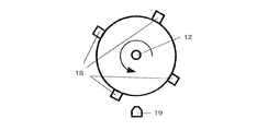
図1、図2の検出器14は、それぞれスリットとエッジの通過検出を行うもので、検出器は発光素子と受光素子で形成され、発光素子と受光素子間にスリットおよびエッジが通過して光の遮断を検知する構成である。さらには、図18のように、被検出部を磁性体18で形成し、検出器を磁気センサ19とした構成で、被検出部の通過を検知する構成でもよい。図1、図2における各々のスリットとエッジ検出器は、回転板12Aの一方の固定部に発光素子と受光素子を形成し反射型で形成してもよい。
The
ここで、被検出部の定義について説明する。図1の被検出部は、回転板12Aのスリットである。また、図2(b)、図4(c)の被検出部は、光遮光部の前側エッジであり、図4(d)の被検出部は光遮光部の後側エッジである。さらに、図2(a)の被検出部は、光遮光部の前側エッジあるいは後側エッジの両方である。一般に、検出器は出力の立ち上がり部と立ち下がり部では、被検出部と検出器設置誤差による距離変動、回路系等で誤差が生じる。そのため、立ち上がり部か立ち下がり部のどちらか統一して計測することで、この誤差を避けることができる。したがって、図1もしくは図2(b)、図4(c)、図4(d)のような構成がよい。このように様々な実施例が考えられるが、本発明では、その機械的な構成のみならず、その処理方式にも限定されることはない。
Here, the definition of the detected part will be described. 1 is a slit of the
また、図1(b)では、2つの検出器14aと14bが感光体ドラム軸12を中心に180度離れた位置に設置されている。これは、感光体ドラム軸12の軸心に対して、回転板の軸心に偏心があった場合に、その偏心による検出誤差を補正するために設置されている。この詳細について図10を用いて説明する。図10では、感光体ドラム回転軸12よりも回転板12Aの軸心20が上側に偏心して取付けられている。このとき、検出器14a、14bでの検出出力について説明する。検出器14aでは、回転軸12の上側を構成する検出区間の角AとBは、本来の感光体ドラム軸12の半回転よりも短い時間で検出され、下側の検出区間の角CとDは、長い時間で検出される。同様に、検出器14bでは、角AとBは本来の感光体ドラム軸12の半回転よりも短い時間で検出され、下側の角CとDは、長い時間で検出される。したがって、対角した角度を180度離れた別々の検出器で検出して、それらの区間の通過時間情報を平均化するような処理をすれば偏心の影響を打ち消すことができる。ここでは、2つの検出器14aと14bが感光体ドラム軸12を中心に180度離れた位置に設置されているとしたが、任意の角度に設置しても偏心の影響を除去できる。
In FIG. 1B, the two
周期変動を検出するための検出区間の角AとB、さらには角CとD、あるいは検出区間AとB間の位相差、検出区間CとD間の位相差の定義については後述する。 The definition of the angles A and B of the detection section for detecting the period fluctuation, the angles C and D, or the phase difference between the detection sections A and B, and the phase difference between the detection sections C and D will be described later.
次に、回転周期変動を検出するために、モータから回転体までの伝達機構で望ましい構成について説明する。たとえば、図33において、被検出部で構成する検出区間AとBあるいは検出区間AとB間の位相差である検出区間ABは、駆動ギヤ10が1回転する間に回転体(感光体ドラム1)が回転する角度の自然数倍とする。言い換えると、検出区間両端での駆動ギヤ10による回転周期変動の位相差は、駆動ギヤ10の回転周期上で360度の整数倍とする。
Next, a desirable configuration of the transmission mechanism from the motor to the rotating body in order to detect the rotation cycle variation will be described. For example, in FIG. 33, a detection section AB, which is a phase difference between the detection sections A and B or the detection sections A and B formed by the detected portion, is a rotating body (photosensitive drum 1) while the
例えば、図7の駆動機構が図9の周波数特性を持つ場合について説明する。図1または図2の検出機構の構成では検出区間は180度であり、検出区間間の位相差である検出区間は90度であるから、駆動ギヤ10が5回転すると従動ギヤ11が4分の1回転する。この構成により、駆動ギヤの1回転周期にわたる歯累積ピッチ誤差や偏心による感光体ドラム1への回転伝達誤差が計測誤差に与える影響を低減できる。したがって、感光体ドラム1の同軸上に設けられた被検出部13および検出器14からなる検出手段の検出精度を上げることができる。
For example, the case where the drive mechanism of FIG. 7 has the frequency characteristics of FIG. 9 will be described. In the configuration of the detection mechanism of FIG. 1 or FIG. 2, the detection section is 180 degrees, and the detection section that is the phase difference between the detection sections is 90 degrees. Therefore, when the
詳細に説明すると、図9のような周波数特性を持つ機構の場合、ドラム1回転は1Hzであるから、検出区間が180度ならば2Hzの検出周期で検出している。したがって、駆動ギヤ1回転に相当する回転周期変動(20Hz)は常に同位相で被検出部を通過する。ここで、位相とは、周期的成分を三角関数で表示したときの引数のことである。物理的に、位相は角度と等価(単位が同一)である。このように、検出器の出力は感光体ドラム軸1回転に相当する回転周期変動(1Hz)による影響を強く受けた出力となる。また、図24のように中間ギヤ23を設けた場合は、図33の検出区間AとBあるいは検出区間の位相差ABを通過する時間が駆動ギヤ10、中間ギヤ23の回転周期の最小公倍数になるように設計することで検出精度を上げることができる。
More specifically, in the case of a mechanism having frequency characteristics as shown in FIG. 9, since one rotation of the drum is 1 Hz, if the detection section is 180 degrees, detection is performed at a detection period of 2 Hz. Therefore, the rotation cycle fluctuation (20 Hz) corresponding to one rotation of the drive gear always passes through the detected portion with the same phase. Here, the phase is an argument when the periodic component is represented by a trigonometric function. Physically, the phase is equivalent to the angle (in the same unit). As described above, the output of the detector is an output that is strongly influenced by the rotation period fluctuation (1 Hz) corresponding to one rotation of the photosensitive drum shaft. Further, when the intermediate gear 23 is provided as shown in FIG. 24, the time that passes through the detection sections A and B in FIG. 33 or the phase difference AB of the detection section is the least common multiple of the rotation cycle of the
前記検出区間の位相差の検出は必ずしも駆動ギヤ10が1回転する間に回転体が回転する角度の自然数倍としなくても、後述するが2回の演算をすれば検出誤差は軽減できる。この場合、演算時間がかかり、少し演算誤差が乗るが検出誤差は軽減できる。
Although the detection of the phase difference in the detection section is not necessarily a natural number multiple of the angle at which the rotating body rotates while the
また、カップリング9b、9cにユニバーサルジョイントを用いると、図32のようにドラム半回転に相当する回転周期変動が発生する場合がある。この場合は、検出区間を180度に構成し、検出区間の位相差を90度にする。この構成にすることで、ドラム半回転に相当する回転周期変動(2Hz)は常に同位相で被検出部を通過する。
In addition, when a universal joint is used for the
また、図7の実施例では駆動ギヤ10の1回転周期は、感光体ドラム1の露光位置から転写体への転写位置までの回転周期に対しても自然数分の1である。このような構成にすることにより、駆動ギヤ10の1回転周期にわたる歯累積ピッチ誤差や偏心により感光体ドラム1への回転伝達誤差が発生しても、露光位置の変動と転写位置の変動が同位相となり、転写画像の位置ずれへの影響を抑えることができる。
Further, in the embodiment of FIG. 7, the rotation period of the
さらに、被検出部13で構成する検出区間が検出器を通過する時間を、駆動ギヤ10の1回転周期の自然数倍となるように構成する。こうすることで、駆動ギヤ10の回転周期変動の影響を受けない検出ができると同時に、転写画像の位置ずれへの影響を抑えることもできる。
Further, the time for which the detection section formed by the detected
最後に、回転周期変動を検出し補正するためのホーム位置検出の構成について説明する。ホーム位置検出の構成で最も一般的な構成は、別の検出器と被検出部を設けることである。これは、回転周期変動検出の回転板に設けなくてもよく、例えば、図21に示すように感光体ドラム軸の同心円上のフランジ1Aに設けてもよい。しかし、こうした方式は検出機構を複雑にする難点があり、新たに検出器を取付けるコストも要する。本発明は上記構成でも達成できるが、上記構成よりも簡易にした構成で実現した。以下、その実施例を説明する。
Finally, a configuration of home position detection for detecting and correcting the rotation cycle variation will be described. The most common configuration for detecting the home position is to provide another detector and a detected portion. This may not be provided on the rotating plate for detecting the rotation cycle variation, and may be provided, for example, on the
まず、ホーム位置検出のために、特別に被検出部を設ける構成について説明する。この場合、図11に示すように感光体ドラム回転軸12を中心に環状に配設された被検出部13の周上に、新たに被基準検出部17を設ける。この場合、検出器14で検出したパルス信号を図16に示す。被検出部13同士の間は、図1、図2にあるように90度で構成されている。つまり、検出器14が被検出部13を検出したときのパルス信号はおおよそ一定間隔となる。そして、検出器14が被基準検出部17を検出したときのパルス信号は、以前のパルスの時間間隔と比較して明らかに小さくなる。したがって、以前のパルスの時間間隔と比較して小さいパルスの時間間隔を検出したら、ホーム位置を通過したと判定できる。そして、図17のフローチャートのように閾値を設けることで被基準検出部17の通過を処理できる。このとき、閾値をパルス信号の時間間隔と比較するが、回転周期変動による時間変動はμsecのオーダーなのに対して、被基準検出部の通過による時間変動はmsecのオーダーなので、msecオーダーの閾値を設けることで、被基準検出部17と被検出部13の判別が可能となる。この被基準検出部17を通過したときのパルス間隔の変化をもって、次に到来するパルスがホーム位置であることが分かるので、これを基準として検出あるいは制御をすることができる。
First, a configuration in which a detected part is specially provided for home position detection will be described. In this case, as shown in FIG. 11, a
次に、ホーム位置検出のために、特別に被検出部を設けない構成について説明する。ここでは、図1(a)の検出機構を用いて説明する。この場合モータが等速回転になったら、図1(a)の被検出部のどれかをホーム位置として、回路あるいはファームウェアで監視して行いく。ホーム位置の設定方法は、モータ回転速度が目標速度に到達した直後に検出したパルス信号に対応する被検出部をホーム位置と設定する。この設定方法を図19に示す。モータが目標速度に到達した直後のパルス信号を検知したと同時にタイマカウンタをリセットして、ホーム位置と設定する。そして、1回転に設けられた被検出部13の数を予め記録して、被検出部13通過時のパルス数を連続してカウントしていけば、常にホーム位置が分かる。この方式では、電源ON時に毎回ホーム位置の決定とそれに対応した補正データを作成する。このとき、どこをホーム位置にしたかは回路あるいはファームウェアで常に認識しておく。以下の実施例でのホーム位置検出はこの方式を採用している。
Next, a configuration in which a detection target part is not provided specifically for home position detection will be described. Here, description will be made using the detection mechanism of FIG. In this case, when the motor rotates at a constant speed, any one of the detected parts shown in FIG. In the home position setting method, the detected portion corresponding to the pulse signal detected immediately after the motor rotation speed reaches the target speed is set as the home position. This setting method is shown in FIG. At the same time as detecting the pulse signal immediately after the motor reaches the target speed, the timer counter is reset to set the home position. If the number of detected
以下、図12を参照して、図7に示した感光体ドラム駆動制御機構の動作について説明する。 The operation of the photosensitive drum drive control mechanism shown in FIG. 7 will be described below with reference to FIG.
図12は、本実施例を示す画像形成装置における感光体ドラム1回転周期変動を軽減するための制御で、モータ回転角速度を補正制御するためのデータ処理から補正制御までの手順の一例を示すフローチャートである。この制御は、図7に示した制御器8に格納される制御プログラムに基づいて処理される。また、検出機構としては図1(a)の構造を持っている。
FIG. 12 is a flowchart showing an example of a procedure from data processing to correction control for correcting the motor rotation angular velocity in control for reducing fluctuations in one rotation cycle of the photosensitive drum in the image forming apparatus according to the present exemplary embodiment. It is. This control is processed based on a control program stored in the
まず、感光体ドラム軸1回転に相当する回転周期変動を軽減する補正制御の前に、そのための補正用情報として、感光体ドラム軸1回転に相当する回転周期変動を検出する。この事前動作は、図16のようにホーム位置が固定の場所に設定できる場合は商品出荷前の製造工程、あるいは感光体ドラム交換時に行っておけば感光体ドラム一回転周期変動を検出しなくても感光体ドラム周期変動補正動作をすぐできるが、ここではホーム位置が固定されて無い場合について述べる。この場合、電源投入後は常に感光体ドラム周期変動を検出しなければならないが、たとえば締結部が経時あるいは環境ですべり等が発生する場合は、あらかじめ規定された時間毎、枚数毎、などにユーザーの使用状況(プリント要求の無いタイミング)に合せたり、作像中に行ったりしてもよい。 First, before the correction control for reducing the rotation cycle fluctuation corresponding to one rotation of the photosensitive drum shaft, the rotation cycle fluctuation corresponding to one rotation of the photosensitive drum shaft is detected as correction information for that purpose. If the home position can be set at a fixed position as shown in FIG. 16, if the pre-operation is performed at the manufacturing process before product shipment or at the time of replacement of the photosensitive drum, it is not necessary to detect a change in the rotation cycle of the photosensitive drum. Although the photosensitive drum cycle fluctuation correction operation can be performed immediately, the case where the home position is not fixed will be described here. In this case, after the power is turned on, it is necessary to always detect the photosensitive drum cycle fluctuation. It may be performed in accordance with the use status (timing when there is no print request) or during image formation.
制御器8はDCサーボモータ6を目標回転角速度ωmで駆動させる指令信号を出力し(ステップS1)、回転駆動する。DCサーボモータ6の図示しない回転角速度検出器から出力される回転速度情報より、制御器8は目標とする回転速度に達したかどうかを判断し(ステップS2)、目標とする回転速度に達しなかった場合はステップS1に戻り、目標とする回転速度に達していると判断した場合、適当なタイミングで被検出部の一つをホーム位置と設定する(ステップS3)。このとき、制御器8にある内蔵タイマユニットのカウンタを0に設定して(ステップS4)、時間を計測していく。
The
検出器14は、感光体ドラム軸に取付けられた被検出部13の通過時にパルス信号15を出力し、制御器8に送信する。制御器8は、パルス信号15を受信したときの内蔵タイマユニットのカウンタで計測された時間をデータメモリに記録する。予め、被検出部の数をデータとして保持しておき、総被検出部数分のパルスが出力されることで感光体ドラム1回転と判断する。そして、1回転に要する時間を計測することで、感光体ドラム1回転の平均回転速度ωdを算出する(ステップS5)。この1回転に要する時間を計測する処理は、モータの速度制御に定常誤差が生じた場合に回転周期変動検出誤差を軽減できる。
The
図28に示すように、再びホーム位置を検出したときから被検出部を通過した順に、通過時間をT1,T2,T3と制御器8に内蔵されているデータ用メモリに記憶していく(ステップS6)。そして、通過時間のデータT1,T2,T3を用いて、ドラム1回転に相当する回転周期変動算出処理を実行する(ステップS7)。このとき、通過時間データT1,T2,T3と検出区間AとB、検出区間の位相差ABの関係を図34に示す。
As shown in FIG. 28, the passage times are stored in T1, T2, T3 and the data memory built in the
ドラム1回転に相当する回転周期変動算出処理(ステップS7)は、感光体ドラム軸1回転に相当する回転周期変動の振幅と位相を算出する機能を持っている。感光体ドラム軸では、図8で示したように回転周期変動が生じる。この変動成分のうち感光体ドラム軸1回転に相当する回転周期変動の振幅をA、ホーム位置を基準とした初期位相をα、平均回転速度ωdをωとして算出する。算出処理は、被検出部のうち2箇所で構成する第1の区間(図34における検出区間の角A)をホーム位置(時間0)から時間T2、被検出部のうち2箇所で構成する第2の区間(図34における検出区間の角B)を時間T1から時間T3、前記第1の区間と第2の区間の位相差(図34における検出区間の角AB)を時間0から時間T1として以下の方程式を解くことで求める。 The rotation cycle variation calculation process (step S7) corresponding to one rotation of the drum has a function of calculating the amplitude and phase of the rotation cycle variation corresponding to one rotation of the photosensitive drum shaft. On the photosensitive drum shaft, the rotation period varies as shown in FIG. Of these fluctuation components, the amplitude of the rotation period fluctuation corresponding to one rotation of the photosensitive drum shaft is A, the initial phase with respect to the home position is α, and the average rotation speed ωd is ω. In the calculation process, the first section (the corner A of the detection section in FIG. 34) configured at two locations in the detected part is time T2 from the home position (time 0), and the first section configured at two positions in the detected section. The second section (the corner B of the detection section in FIG. 34) is the time T1 to the time T3, and the phase difference between the first section and the second section (the detection section angle AB in FIG. 34) is the time 0 to the time T1. It is obtained by solving the following equation.

上式(1)は、左辺の行列の逆行列を求めて解いても良いし、他の数値計算手法を利用しても良い。 The above equation (1) may be solved by obtaining an inverse matrix of the matrix on the left side, or other numerical calculation methods may be used.
これで、感光体ドラム軸1回転周期の変動成分の振幅Aとホーム位置を基準とした位相αが求まる。このAとαの演算処理が終了後、モータ速度補正処理を実行する(ステップS8)。まず、モータとドラムの減速比を考慮して振幅A’をモータ軸回転速度の周期変動振幅に換算する(ステップS8−1)。次に、位相αにπを加算して逆位相に換算する(ステップS8−2)。ステップS8−1とステップS8−2で算出された振幅A’と位相α’で正弦信号を生成し、現在のモータ回転目標速度ωmと合成し、補正したモータ回転目標速度ωm’を生成する(ステップS8−3)。補正したモータ回転目標速度ωm’は、ホーム位置を基準とする時間tに対して、式(2)の通りに表現される。 Thus, the amplitude α of the fluctuation component of one rotation cycle of the photosensitive drum shaft and the phase α based on the home position are obtained. After the calculation process of A and α is completed, a motor speed correction process is executed (step S8). First, the amplitude A 'is converted into a periodic fluctuation amplitude of the motor shaft rotation speed in consideration of the reduction ratio of the motor and the drum (step S8-1). Next, π is added to the phase α to convert it to an opposite phase (step S8-2). A sine signal is generated with the amplitude A ′ and the phase α ′ calculated in steps S8-1 and S8-2, and is combined with the current motor rotation target speed ωm to generate a corrected motor rotation target speed ωm ′ ( Step S8-3). The corrected motor rotation target speed ωm ′ is expressed as shown in Expression (2) with respect to the time t based on the home position.
ωm’=ωm+A’sin(ωd×t+α’) ・・・式(2) ωm ′ = ωm + A′sin (ωd × t + α ′) (2)
補正したモータ回転目標速度ωm’は、制御器8のメモリ内のモータ回転目標速度ωmに記憶される。
The corrected motor rotation target speed ωm ′ is stored in the motor rotation target speed ωm in the memory of the
そして、ホーム位置と同期をとって、モータ回転目標速度ωmを指令信号として与え(ステップS9)、感光体ドラム1回転に相当する回転周期変動を抑制する。前記第の1区間と第2の区間の位相差を時間0から時間T1は検出感度が下がるけれども、必ずしもπ/2でなくても検出可能である。 Then, in synchronization with the home position, the motor rotation target speed ωm is given as a command signal (step S9), and the rotation cycle fluctuation corresponding to one rotation of the photosensitive drum is suppressed. The phase difference between the first section and the second section can be detected even if it is not necessarily π / 2, although the detection sensitivity decreases from time 0 to time T1.
また、図20に示す最少の被検出部構成では、図37のように通過時間を検出した場合、感光体ドラム1回転に相当する回転周期変動は、次の式(3)の通りになる。 Further, in the minimum configuration of the detection target portion shown in FIG. 20, when the passage time is detected as shown in FIG. 37, the rotation cycle fluctuation corresponding to one rotation of the photosensitive drum is expressed by the following equation (3).
図37において、第1の区間の角Aと第2の区間の角Bをモータ回転数の自然数倍回転する角度にすれば、この区間の時間計測は精度が向上し、感光体ドラム1回転に相当する回転周期変動検出が高精度になる。 In FIG. 37, if the angle A of the first section and the angle B of the second section are set to an angle that rotates a natural number times the motor rotation speed, the time measurement in this section improves the accuracy, and the photosensitive drum rotates once. Rotational period variation detection corresponding to is highly accurate.
本実施例では、各色の感光体ドラム1回転に相当する回転周期変動に起因して発生する色ずれを低減するために、各色の感光体ドラムの1回転に相当する回転周期変動の位相を合せる方式について説明する。この方式は、基準となる感光体ドラムの回転周期変動の位相に対して、他の複数の感光体ドラムが所定の位相差で回転するように駆動モータをそれぞれ独立に回転駆動し、各色の感光体ドラム上の同一画素における感光体ドラムの1回転に相当する回転周期変動位相を調整し、転写紙上で前記同一画素を前記回転周期変動位相が一致するように重ね、副走査方向の色ずれを低減し、画像品質の劣化を防ぐことが可能となる。前記位相を一致させるためには、ある一定時間においてモータの回転速度を目標速度よりも速くする又は遅くすることにより調整を行う。 In this embodiment, in order to reduce the color shift caused by the rotation period fluctuation corresponding to one rotation of the photosensitive drum of each color, the phases of the rotation period fluctuations corresponding to one rotation of the photosensitive drum of each color are matched. The method will be described. In this method, the drive motors are rotated independently so that a plurality of other photosensitive drums rotate with a predetermined phase difference with respect to the phase of the rotation cycle fluctuation of the reference photosensitive drum, and the photosensitive drums of the respective colors are driven. The rotation cycle variation phase corresponding to one rotation of the photosensitive drum at the same pixel on the body drum is adjusted, and the same pixel is overlapped on the transfer paper so that the rotation cycle variation phase coincides, and the color shift in the sub-scanning direction is corrected. It is possible to reduce and prevent deterioration of image quality. In order to make the phases coincide with each other, adjustment is performed by making the rotational speed of the motor faster or slower than the target speed for a certain period of time.
実施例1と同様に図6、図7で示した画像形成装置の構成で、図1(a)の検出機構を有する場合について説明する。図13に示すように、4つの感光体ドラムを1a,1b,1c,1dとし、このうち一番端部にある6aの感光体ドラム駆動系を基準に他3つの感光体ドラム1回転に相当する回転周期変動の位相を合せる。ここでは、ベルト速度と感光体ドラム平均周速が等しく駆動されているとする。位相合せのための基準位置として、図13の各感光体ドラム上に示されている矢印位置を設定する。この位相合せのための基準位置(矢印位置)は、各感光体ドラムの感光体ドラム1回転に相当する回転周期変動が同位相となる位置を示している。したがって、各感光体ドラムに示した矢印位置で転写するとき、各感光体ドラムの回転周期変動が同位相の状態で転写される。こうすることで、4つの感光体ドラム上に形成される画像がベルトまたは転写紙に転写するとき、それぞれの回転周期変動は同位相で重ね合わされる。こうした転写時の回転周期変動の位相を合せるためには、感光体ドラム間距離分の位相差を設ける必要がある。詳細には、図13の感光体ドラム1aの矢印が転写するときに、次に転写する感光体ドラム1bの矢印は、感光体ドラム間距離をL、感光体ドラム径をφとしL>πφとすると、回転角度をL/πφ×2π=2L/φ[rad]分だけ位相を遅らせて回転させればよい。
Similar to the first embodiment, the case where the image forming apparatus shown in FIGS. 6 and 7 has the detection mechanism shown in FIG. 1A will be described. As shown in FIG. 13, the four photosensitive drums are denoted by 1a, 1b, 1c, and 1d, and among these, the other three photosensitive drums are rotated once based on the photosensitive
同様に、感光体ドラム1c,1dの各矢印位置を感光体ドラム1aの矢印位置と合せるためには、回転角度を4L/φ、6L/φ[rad]分だけ位相を遅らせて回転させればよい。
Similarly, in order to align each arrow position of the
L<πφのときは感光体ドラム1bから1dは感光体ドラム1aに対して回転周期変動位相を進めて回転させる。
When L <πφ, the
上記回転位相差を設けて感光体ドラム1a〜1dを駆動するとき、感光体ドラム1aの矢印の地点で転写した画素の上に、感光体ドラム1bの矢印の地点にある画素が重ね合わされる。同様に、感光体ドラム1c,1dでは矢印が転写位置に到達したときの画素が重ね合わされる。
When driving the
図1(a)のように被検出部はドラム4分の1回転ごとに設けて、位相合せのための基準位置を調整する方法をL>πφとして、図14と図15、図30のフローチャートを用いて説明する。まず、各感光体ドラム1a〜1dでドラム1回転に相当する回転周期変動の振幅と位相を算出する(図30のステップS1)。この算出方法は、実施例1で説明した方法を用いて達成する。次に、図14に示すように各感光体ドラム上の回転板にあるホーム位置から位相合せの基準位置までの位相差(角度)をα1〜α4とする(図30のステップS2)。感光体ドラム1aにおける位相合せ基準位置が転写の位置(真下)に到達するときに、他の感光体ドラム1b,1c,1dにおける位相合せ基準位置は、図15にする。そのために、夫々の感光体ドラム回転を以下の回転位相(角度)だけ調整する(図30のステップS3〜S6)。なお、図30のステップS2−1〜S2−4はステップS2のサブルーチンであり、次の式(4)が実行される。
As shown in FIG. 1A, the detected portion is provided for each quarter rotation of the drum, and the method of adjusting the reference position for phase alignment is set as L> πφ, and the flowcharts of FIGS. Will be described. First, the amplitude and phase of rotation cycle fluctuation corresponding to one drum rotation are calculated for each of the
実施例2では、各色の感光体ドラム1回転に相当する回転周期変動の位相を合せる方法のみを述べた。さらに、実施例1で述べた回転周期変動の補正も実施することができる。この場合、実施例2の位相合せで各感光体ドラム間の位相合せを実施後、各感光体ドラムの回転周期変動を実施例1に基づいて補正制御する。前記各感光体ドラム回転位相の調整は以下のようにすればよい。 In the second embodiment, only the method of matching the phase of the rotation period variation corresponding to one rotation of the photosensitive drum of each color has been described. Furthermore, the correction of the rotation period variation described in the first embodiment can also be performed. In this case, after the phase alignment between the photosensitive drums is performed in the phase alignment of the second embodiment, the rotational cycle variation of each photosensitive drum is corrected and controlled based on the first embodiment. The photosensitive drum rotational phase may be adjusted as follows.
図6の制御器5内のタイマーで感光体ドラム一回転時間に相当する基準となる基準信号Trefが生成される。この信号は感光体ドラム駆動制御器8へ送られる。感光体ドラム駆動制御器8は以下のように制御する。感光体ドラム1aの回転は、基準信号Tref到来後、図15におけるホーム位置が図1における検出器14を通過してθ1/ωd時間の位置になるように感光体ドラム速度を加減速して制御する。感光体ドラム1bの回転は、基準信号Tref到来後、ホーム位置が検出器14を通過してθ2/ωd時間の位置になるように感光体ドラム速度を加減速して制御する。以下同様に感光体ドラム1cと1dの回転が制御され、感光体ドラム一回転周期変動の位相を調整する。
A reference signal Tref serving as a reference corresponding to one rotation time of the photosensitive drum is generated by a timer in the
このようにすると感光体ドラム一回転周期変動の振幅が低減でき、かつ制御誤差等で残った感光体ドラム一回転周期変動があって感光体ドラム間の前記周期変動の位相合せをしてあるので色ずれ発生を抑えることができるのでより高画質化が図れる。 In this way, the amplitude of the rotation variation of the photosensitive drum can be reduced, and the rotation variation of the photosensitive drum remaining due to a control error or the like is present, and the phase variation between the photosensitive drums is phase-matched. Since the occurrence of color misregistration can be suppressed, higher image quality can be achieved.
実施例1では、図19のような検出機構の構成でホーム位置を設定した。本実施例では、ホーム位置を設定するために被基準検出部が設けられている。被基準検出部の検出機構は図16ような構成を有し、そのデータ処理を図29のフローチャートに示す。図29において、ステップS5までは、実施例1と同様の手順をとっている。そして、図26に示すように、被基準検出部17を通過した時点から被検出部を通過した順に、通過時間をT0,T1,T2,T3と制御器8に内蔵されているデータ用メモリに記憶していく(ステップS6)。そして、通過時間のデータT0,T1,T2,T3を用いて、ドラム1回転に相当する回転周期変動算出処理を実行する(ステップS7)。
In the first embodiment, the home position is set with the configuration of the detection mechanism as shown in FIG. In this embodiment, a reference detection unit is provided to set the home position. The detection mechanism of the reference detection unit has a configuration as shown in FIG. 16, and its data processing is shown in the flowchart of FIG. In FIG. 29, steps up to step S5 are the same as those in the first embodiment. Then, as shown in FIG. 26, the passage times are stored in T0, T1, T2, T3 and the data memory built in the
ステップS7のドラム1回転に相当する回転周期変動算出処理は、感光体ドラム軸1回転に相当する回転周期変動の振幅と位相を算出する機能を持っている。感光体ドラム軸では、図8で示したように回転周期変動が生じる。この変動成分のうち感光体ドラム軸1回転に相当する回転周期変動の振幅をA、ホーム位置を基準とした初期位相をαとして算出する。算出処理は、以下の方程式を解くことで求める。 The rotation cycle variation calculation process corresponding to one rotation of the drum in step S7 has a function of calculating the amplitude and phase of the rotation cycle variation corresponding to one rotation of the photosensitive drum shaft. On the photosensitive drum shaft, the rotation period varies as shown in FIG. Of these fluctuation components, the amplitude of the rotation period fluctuation corresponding to one rotation of the photosensitive drum shaft is calculated as A, and the initial phase with reference to the home position is calculated as α. The calculation process is obtained by solving the following equation.
上式(5)は、左辺の行列の逆行列を求めて解いても良いし、他の数値計算手法を利用しても良い。 The above equation (5) may be solved by obtaining an inverse matrix of the left-hand side matrix, or other numerical calculation methods may be used.
これで、感光体ドラム軸1回転周期の変動成分の振幅Aとホーム位置を基準とした位相αが求まる。このAとαの演算処理が終了後、モータ速度補正処理を実行する(ステップS8)。ステップS8−1〜ステップS8−3では実施例1と同様な処理を行う。そして、モータ回転目標速度ωmの指令信号を出力する(ステップS9)。 Thus, the amplitude α of the fluctuation component of one rotation cycle of the photosensitive drum shaft and the phase α based on the home position are obtained. After the calculation process of A and α is completed, a motor speed correction process is executed (step S8). In step S8-1 to step S8-3, processing similar to that in the first embodiment is performed. Then, a command signal for the motor rotation target speed ωm is output (step S9).
この方式の利点は、ホーム位置を決定するための処理を省けることと、そのための記憶領域を確保しなくてよいことである。 The advantage of this method is that the processing for determining the home position can be omitted, and a storage area for that purpose need not be secured.
実施例1では、感光体ドラム上の光書き込み位置と転写材(紙または中間転写ドラム、中間転写ベルト)への転写位置とが180度の位置にある場合の構成となっている。しかし、画像形成装置全体のレイアウト上からこのような構成でない場合の実施例について図3と図4を用いて説明する。 In the first embodiment, the optical writing position on the photosensitive drum and the transfer position to the transfer material (paper, intermediate transfer drum, intermediate transfer belt) are 180 degrees. However, an embodiment without such a configuration will be described with reference to FIGS. 3 and 4 in view of the layout of the entire image forming apparatus.
図3に示すように、画像形成装置は、モータ自然数回転分で感光体ドラムは露光から転写位置まで到達するように設計される。これは、モータ回転速度の周期変動を露光と転写位置で位相合せをするためである。この位相合せにより、転写される画素の位置ずれは低減される。この位相合せ検出でも行う。つまり、この露光と転写位置の角度がγであった場合、モータ回転速度の周期変動がドラム1回転に相当する回転周期変動の検出に影響しないように、被検出部が構成する検出区間の角度をγとする。こうして、モータ回転速度の周期変動が常に同位相の状態で検出できるため、検出上はモータ回転速度の周期変動がないものとして検出できる。このとき、被検出部としては、図4(a)、図4(b)、図4(c)、図4(d)のような構成がある。図4(a)と図4(b)は、被検出部を回転板のエッジ両端とする構成であり、図4(c)と図4(d)は、被検出部を回転板エッジの片側とする構成である。 As shown in FIG. 3, the image forming apparatus is designed so that the photosensitive drum reaches the transfer position from the exposure by the natural number of rotations of the motor. This is because phase fluctuations of the motor rotation speed are phase-matched at the exposure and transfer positions. By this phase matching, the positional deviation of the transferred pixel is reduced. This phase alignment detection is also performed. In other words, when the angle between the exposure and the transfer position is γ, the angle of the detection section formed by the detected portion is set so that the period fluctuation of the motor rotation speed does not affect the detection of the rotation period fluctuation corresponding to one rotation of the drum. Is γ. Thus, since the periodic fluctuation of the motor rotational speed can always be detected in the same phase, it can be detected that there is no periodic fluctuation of the motor rotational speed on detection. At this time, the detected part has configurations as shown in FIGS. 4A, 4B, 4C, and 4D. 4 (a) and 4 (b) show a configuration in which the detected part has both edges of the rotating plate, and FIGS. 4 (c) and 4 (d) show the detected part on one side of the rotating plate edge. The configuration is as follows.
このような検出器を用いた場合でも、感光体ドラム1回転に相当する回転周期変動の振幅および位相の検出手順と駆動制御方法または感光体ドラム間の位相合せ方法は、実施例1と実施例2と同様であり、式(1)におけるπをγとした計算式で回転周期変動を算出できる。 Even when such a detector is used, the procedure for detecting the amplitude and phase of the rotation period variation corresponding to one rotation of the photosensitive drum, the drive control method, and the phase matching method between the photosensitive drums are the same as those in the first embodiment. The rotation period variation can be calculated by a calculation formula in which π in formula (1) is γ.
図40におけるホーム位置はホーム位置に到来するまでの検出器14で検出される区間のパルス間隔が他の区間のパルス間隔は異なるので判定して検出できる。
The home position in FIG. 40 can be determined and detected because the pulse interval of the section detected by the
このとき、図40においてホーム位置からの角度γ1=γを通過する時間がT2であり、角度γ2=γがホーム位置から通過する時間がT3−T1である。この期間の時間検出はモータ回転速度の周期変動の影響を受けない。 At this time, in FIG. 40, the time for passing the angle γ1 = γ from the home position is T2, and the time for the angle γ2 = γ to pass from the home position is T3-T1. The time detection during this period is not affected by the periodic fluctuation of the motor rotation speed.
ここで時間T3+T1が精度よく検出できればさらに検出精度がよくなる。図40における角度Pdもモータ回転周期変動の影響を受けないようにモータ自然数回転分で感光体ドラムの回転角度Pdとなるように構成する。ここの通過時間はT1である。T3+T1=(T3−T1)+2T1となり、右辺第1項は角度γ2を通過する時間であり、第2項は角度Pdを通過する時間である。したがって、時間T3+T1も精度よく検出できるようになる。つまり、実施例1で示した式(1)は、下記の式(6)となる。 Here, if the time T3 + T1 can be accurately detected, the detection accuracy is further improved. The angle Pd in FIG. 40 is also configured to be the rotation angle Pd of the photosensitive drum by the natural number of rotations of the motor so as not to be affected by fluctuations in the motor rotation cycle. The transit time here is T1. T3 + T1 = (T3-T1) + 2T1, where the first term on the right side is the time for passing through the angle γ2, and the second term is the time for passing through the angle Pd. Therefore, the time T3 + T1 can be detected with high accuracy. That is, the formula (1) shown in the first embodiment becomes the following formula (6).
また、式(5)におけるπをγとした計算式でも回転周期変動を算出できる。つまり、実施例3で示した式(5)は、下記の式(7)となる。 In addition, the rotation period variation can be calculated by a calculation formula in which π in Formula (5) is γ. That is, the formula (5) shown in the third embodiment is the following formula (7).
式(6)あるいは式(7)を式(1)あるいは式(5)の代わりに演算処理することで、被検出部間の角度が180度でない一般的な構成でもドラム1回転に相当する回転周期変動の振幅と位相を検出できる。 Rotation equivalent to one rotation of the drum even in a general configuration in which the angle between the detected parts is not 180 degrees by calculating the expression (6) or (7) instead of the expression (1) or (5) The amplitude and phase of the period variation can be detected.
図4(a)において、モータが自然数倍回転したとき感光体ドラムの回転角がPdとならない場合の構成では、回転角度Pdを通過する時間にはモータ回転周期変動による検出誤差がある。この誤差を補正する方法について述べる。まず、図4(a)における角γ1と角γ2を通過する時間を用いて、ドラム1回転に相当する回転周期変動を式(6)で求める。次に、角γ2と角γ3を通過する時間を用いて、ドラム1回転に相当する回転周期変動を求める。これは、ホーム位置から角γ3までの通過時間をT4とすると、次の式(8)で回転周期変動を求めることができる。 In FIG. 4A, in the configuration in which the rotation angle of the photosensitive drum does not become Pd when the motor rotates by a natural number, there is a detection error due to fluctuations in the motor rotation cycle in the time passing through the rotation angle Pd. A method for correcting this error will be described. First, using the time passing through the angle γ1 and the angle γ2 in FIG. 4A, the rotation period fluctuation corresponding to one rotation of the drum is obtained by Expression (6). Next, using the time passing through the angle γ2 and the angle γ3, the rotation cycle fluctuation corresponding to one rotation of the drum is obtained. Assuming that the passing time from the home position to the angle γ3 is T4, the rotation cycle variation can be obtained by the following equation (8).
角γを通過する時間であるT2,T3−T1,T4−T2は、モータの回転周期変動による検出誤差は小さい。しかし、T3+T1=(T3−T1)+2T1とT4+T2−2T1=(T4−T2)+2(T2−T1)の2式における第2項はモータの回転周期変動による検出誤差が出る。ここで、時間T2―T1を検出する区間と時間T1を検出する区間の和は検出区間の角γ1のT2時間であるので、時間T2−T1の検出誤差と時間T1の検出誤差の和はゼロになる。したがって、式(6)と式(8)より求めた回転周期変動の平均値(両者で求めた回転周期変動の和の2分の1)を求めれば誤差が低減される。 T2, T3-T1, and T4-T2, which are times passing through the angle γ, have a small detection error due to fluctuations in the rotation period of the motor. However, the second term in the two formulas T3 + T1 = (T3−T1) + 2T1 and T4 + T2-2T1 = (T4−T2) +2 (T2−T1) causes a detection error due to the rotation cycle variation of the motor. Here, since the sum of the section for detecting time T2-T1 and the section for detecting time T1 is T2 time of the angle γ1 of the detection section, the sum of the detection error at time T2-T1 and the detection error at time T1 is zero. become. Therefore, the error can be reduced by obtaining the average value of the rotational cycle fluctuations obtained from the equations (6) and (8) (1/2 of the sum of the rotational cycle variations obtained by both).
実施例1から4では、感光体ドラム軸に設置された大口径歯車である従動ギヤ11の1回転周期の回転周期変動を検出し制御することで、画像の位置ずれを抑えることができる。また、感光体ドラムを一定速度で回転させることにより、感光体ドラムから転写体(転写紙、中間転写ドラム、中間転写ベルト)への転写時の感光体と転写体との速度差変動を軽減できるので、転写時の画素の崩れ(画素の太り)を抑えることができる。
In the first to fourth embodiments, it is possible to suppress the image misalignment by detecting and controlling the rotation cycle variation of one rotation cycle of the driven
しかし、駆動ギヤ10の偏心や歯累積ピッチ誤差による、駆動ギヤ10の1回転に相当する回転周期変動が画素の崩れ(画素の太り)を発生させる場合がある。したがって、駆動ギヤ10の1回転周期の回転周期変動を検出し制御することは、高画質を実現する上で非常に有効である。
However, the rotation period fluctuation corresponding to one rotation of the
ここでは、感光体ドラム軸上の歯車とそれ以外の歯車の1回転に相当する回転周期変動を検出し制御する実施例について説明する。 Here, an embodiment will be described in which a rotation cycle variation corresponding to one rotation of the gear on the photosensitive drum shaft and other gears is detected and controlled.
今、感光体ドラム1回転の周期変動を実施例1で示した方法で取り除いたとする。この状態から、モータ軸歯車などの他の伝達機構が持つ回転周期変動の位相と振幅を検出し、補正制御していく。この方式を、図5のエッジ検出型の回転板を用いて説明する。図5の回転板は、異なる複数の扇状部材における前側エッジのエッジ間が感光体ドラム半回転に相当する角度γからなる第1区間の角γ1と第2区間の角γ2をもち、さらに、扇状部材のエッジ間がモータ軸半回転に相当する角度βからなるモータ回転周期変動を検出するための第1区間の角β1と第2区間の角β2をもつ。角度γ1とγ2は、実施例1や実施例3で述べたように、感光体ドラム1回転に相当する回転周期変動の振幅と位相を検出するための角度であり、露光と転写位置がなす角度に合わせるようにしてもよい。さらにモータ回転数の自然数倍の回転角が角γさらにはこの実施例の場合は角γ/2に一致させれば検出精度は向上する。 Now, assume that the period fluctuation of one rotation of the photosensitive drum is removed by the method shown in the first embodiment. From this state, the phase and amplitude of the rotation cycle variation of other transmission mechanisms such as motor shaft gears are detected and corrected. This method will be described using the edge detection type rotating plate of FIG. The rotating plate in FIG. 5 has a first section angle γ1 and a second section angle γ2 formed by an angle γ corresponding to half rotation of the photosensitive drum between the edges of the front edges of a plurality of different fan-shaped members. Between the edges of the member, there is an angle β1 of the first section and an angle β2 of the second section for detecting a motor rotation cycle fluctuation having an angle β corresponding to half rotation of the motor shaft. As described in the first and third embodiments, the angles γ1 and γ2 are angles for detecting the amplitude and phase of the rotation cycle fluctuation corresponding to one rotation of the photosensitive drum, and are the angles formed by the exposure and transfer positions. You may make it match. Further, if the rotation angle that is a natural number times the motor rotation number is made equal to the angle γ, or in this embodiment, the angle γ / 2, the detection accuracy is improved.
一方、角度β1とβ2あるいは図5における角β/2は、モータ軸1回転に相当する回転周期変動の振幅と位相を検出するための角度である。ここで、γとβをそれぞれ感光体ドラムとモータ軸の半回転に相当する角度にしたのは検出感度が最も高いためである。また、大口径歯車を感光体ドラムと同軸にして駆動させるような方式は、γとβの角度が大きく異なる。したがって、どの回転角度を検出しているかを容易に判定できる。つまり、回転速度は大きく変わらないので時間間隔によってどちらの角度を計測しているかを判定できる。そのため、どちらの角度を検出しているのかは、特別な機構を追加することなく、信号処理上で解決できる。こうして、感光体ドラム1回転の回転周期変動を補正した後、回転周期変動の大きな要因はモータ軸1回転に相当する回転周期変動となるので、モータ軸1回転に相当する回転周期変動をも高精度に検出/制御できる。この関係を図25に示した。 On the other hand, the angles β1 and β2 or the angle β / 2 in FIG. 5 are angles for detecting the amplitude and phase of the rotation cycle fluctuation corresponding to one rotation of the motor shaft. Here, γ and β are set to angles corresponding to half rotations of the photosensitive drum and the motor shaft, respectively, because the detection sensitivity is the highest. Further, the method in which the large-diameter gear is driven coaxially with the photosensitive drum is greatly different in the angles γ and β. Therefore, it can be easily determined which rotation angle is detected. That is, since the rotation speed does not change greatly, it can be determined which angle is measured based on the time interval. Therefore, which angle is detected can be solved in signal processing without adding a special mechanism. Thus, after correcting the rotation cycle variation of one rotation of the photosensitive drum, the major factor of the rotation cycle variation is the rotation cycle variation corresponding to one rotation of the motor shaft, so the rotation cycle variation corresponding to one rotation of the motor shaft is also high. It can be detected / controlled with accuracy. This relationship is shown in FIG.
上記、モータ軸の1回転周期が感光体ドラム1/2回転周期(角γ)あるいは1/4回転周期(角γ/2)の自然数分の1という関係は、数式で表現するとβ×N=πあるいはβ×N=π/2(N:自然数)という関係となる。
The relationship that the one rotation cycle of the motor shaft is a natural fraction of the
図5においては、検出区間の角β1と角β2あるいは角β/2の構成を二つ示したが検出区間の角β1と角β2あるいは角β/2を構成できれば実施可能である。また図5においては一組だけの検出区間の角β1と角β2あるいは角β/2しか設けてないが複数組設けて、複数組のモータ回転周期変動を求めて平均化することにより検出精度を上げてもよい。 FIG. 5 shows two configurations of the angle β1 and the angle β2 or the angle β / 2 of the detection section. However, the present invention can be implemented if the angle β1 and the angle β2 or the angle β / 2 of the detection section can be configured. Further, in FIG. 5, only one set of detection section angles β1 and β2 or β / 2 is provided, but a plurality of sets are provided, and a plurality of sets of motor rotation cycle fluctuations are obtained and averaged to obtain detection accuracy. May be raised.
本実施例では、モータ軸(駆動ローラ)の1回転に相当する回転周期変動について説明したが、この方式はトルクリップルに対しても実施可能である。トルクリップルは、モータが1回転する間に発生する周期的なトルクの変動であるため、この変動周期の半分に対応する第1区間と第2区間あるいはこれら区間の位相差がこの区間の半分となる構成が取れるように図5の円板上の扇状部材をさらに構成してトルクリップルの周期変動を検出して補正制御できる。 In the present embodiment, the rotation cycle variation corresponding to one rotation of the motor shaft (drive roller) has been described, but this method can also be implemented for torque ripple. Since the torque ripple is a periodic torque fluctuation that occurs during one rotation of the motor, the first and second sections corresponding to half of this fluctuation period or the phase difference between these sections is half of this section. The fan-shaped member on the disk shown in FIG. 5 can be further configured to detect the periodic fluctuation of the torque ripple so that the following configuration can be obtained.
本実施例では、図7のような1対のギヤで感光体ドラムを駆動しているが、この歯車機構を増やして中間ギヤを設けた場合でも可能である。この駆動機構を図24に示す。このとき、中間ギヤの変動周期の半分に対応する第1区間と第2区間あるいはこれら区間の位相差がこの区間の半分となる構成が取れるように図5の回転板上の扇状部材をさらに構成して中間ギヤの周期変動を検出して補正制御できる。 In this embodiment, the photosensitive drum is driven by a pair of gears as shown in FIG. 7, but it is possible even when an intermediate gear is provided by increasing this gear mechanism. This drive mechanism is shown in FIG. At this time, the fan-shaped member on the rotating plate of FIG. 5 is further configured so that the first section and the second section corresponding to half the fluctuation period of the intermediate gear or the phase difference between these sections can be half of this section. Thus, it is possible to perform correction control by detecting the period variation of the intermediate gear.
これまでの実施例では、被検出部を有する回転板の軸と感光体ドラムの回転軸が同軸であることを前提に説明してきた。回転板に取付け偏心がある場合、被検出部が検出器を通過する時間は、取付け偏心による通過時間誤差を含むことになる。この時間誤差によって、検出精度が低下し、補正制御の効果が低下するという問題がある。本実施例では、取付け偏心を補正するために、検出器を2個利用する方式について説明する。 In the embodiments so far, the description has been made on the assumption that the axis of the rotating plate having the detected portion and the axis of rotation of the photosensitive drum are coaxial. When the rotating plate has mounting eccentricity, the time for the detected portion to pass through the detector includes a passing time error due to mounting eccentricity. Due to this time error, there is a problem that the detection accuracy is lowered and the effect of the correction control is lowered. In this embodiment, a method of using two detectors in order to correct the mounting eccentricity will be described.
第一の方式として、通過時間そのものを補正する方式がある。ここでは、図10のように感光体ドラム回転軸に対向する位置に検出器14aと14bを取付けた場合について説明する。図35のように、通過時間が得られたとする。このとき、補正した通過時間T1,T2,T3は、
T1=(T1a+T1b)/2
T2=(T2a+T2b)/2
T3=(T3a+T3b)/2
となる。この補正した通過時間T1,T2,T3を式(1)に代入する。こうすることで、回転板取付け偏心の影響を補正して、感光体ドラム回転軸の回転周期変動を高精度に検出できる。
As a first method, there is a method of correcting the passage time itself. Here, a case where the
T1 = (T1a + T1b) / 2
T2 = (T2a + T2b) / 2
T3 = (T3a + T3b) / 2
It becomes. The corrected passage times T1, T2, and T3 are substituted into equation (1). By so doing, it is possible to correct the influence of the eccentricity of the rotating plate and detect the rotation cycle variation of the photosensitive drum rotating shaft with high accuracy.
第二の方式として、各検出器で求めた周期変動を合成して補正する方式がある。ここでは、図35の検出器14aと14bでそれぞれ、以下の回転周期変動を検出した場合について説明する。
14a:Aa・sin(ωd・t+αa)
14b:Ab・sin(ωd・t+αb)
このとき、回転板取付け偏心を補正した回転周期変動は、以下の通りになる。
As a second method, there is a method of correcting by synthesizing periodic fluctuations obtained by each detector. Here, a case where the following rotation cycle fluctuations are detected by the
14a: Aa · sin (ωd · t + αa)
14b: Ab · sin (ωd · t + αb)
At this time, the rotation period fluctuation | variation which correct | amended the rotating plate attachment eccentricity is as follows.
{Aa・sin(ωd・t+αa)+Ab・sin(ωd・t+αb)}/2
・・・式(9)
{Aa · sin (ωd · t + αa) + Ab · sin (ωd · t + αb)} / 2
... Formula (9)
こうして、式(9)を演算することで、回転板取付け偏心の影響を補正した感光体ドラム回転軸の回転周期変動を求めることができる。 Thus, by calculating the equation (9), it is possible to obtain the rotation cycle variation of the photosensitive drum rotating shaft in which the influence of the eccentricity of the rotating plate mounting is corrected.
また、2個の検出器が対向する位置にない場合において、回転板取付け偏心を補正する方法について述べる。ここでは、図38のように検出器14aと14bが対向する位置ではなく、感光体ドラムの回転軸12を中心に角度θだけ離れて配置した場合について説明する。この場合、回転板取付け偏心の影響はθ分の位相がずれている。したがって、図39のように、回転周期変動を合成すれば回転板取付け偏心の影響を補正できる。
A method for correcting the eccentricity of the rotating plate when the two detectors are not located at opposite positions will be described. Here, a case will be described in which the
まず、検出器14a,14bで検出した回転周期変動Aa・sin(ωd・t+αa),Ab・sin(ωd・t+αb)のうち、検出器14bで検出した回転周期変動の位相をπ−θ分ずらして、Ab・sin(ωd・t+αb−(π−θ))という回転周期変動を生成する。
First, among the rotation period fluctuations Aa · sin (ωd · t + αa) and Ab · sin (ωd · t + αb) detected by the
次に、検出器14aの回転周期変動Aa・sin(ωd・t+αa)とπ−θ位相をずらした検出器14bの回転周期変動Ab・sin(ωd・t+αb−(π−θ))を合成して1/2化する。この結果、回転周期変動は以下の通りになる。
Next, the rotational period variation Aa · sin (ωd · t + αa) of the
{Aa・sin(ωd・t+αa)+Ab・sin(ωd・t+αb−(π−θ))}/2
・・・式(10)
{Aa · sin (ωd · t + αa) + Ab · sin (ωd · t + αb− (π−θ))} / 2
... Formula (10)
こうして、式(10)を演算することで、回転板取付け偏心の影響を補正した感光体ドラム回転軸の回転周期変動を求めることができる。 Thus, by calculating the equation (10), it is possible to obtain the rotation cycle variation of the photosensitive drum rotating shaft in which the influence of the eccentricity of the rotating plate mounting is corrected.
これまでの実施例では、検出と補正制御の一連の実施例について述べてきた。本実施例では、この検出と補正制御を繰り返して実施することについて述べていく。これは、経時的に回転周期変動が変化する場合に有効である。この経時的変化は、感光体ドラム回転軸と駆動軸の結合部のガタにより、偏心の状態が変化する場合が考えられる。 In the embodiments so far, a series of embodiments of detection and correction control have been described. In the present embodiment, it will be described that this detection and correction control are repeatedly performed. This is effective when the rotation cycle variation changes with time. This change with time is considered to be a case where the state of eccentricity changes due to backlash at the coupling portion between the photosensitive drum rotating shaft and the drive shaft.
逐次的な補正制御における、モータ目標速度の決定方法について説明する。実施例1の逐次的な検出と補正制御は、機構構成を変えることなく、図31のフローチャートに沿って達成できる。このとき、モータ目標速度は、前回の補正したモータ目標速度と今回生成した補正モータ目標速度を合成する。 A method for determining the motor target speed in the sequential correction control will be described. The sequential detection and correction control of the first embodiment can be achieved along the flowchart of FIG. 31 without changing the mechanism configuration. At this time, the motor target speed is composed of the previously corrected motor target speed and the corrected motor target speed generated this time.
この逐次的な繰り返しによる検出と補正制御は、画像形成中だけでなく、常時または一定間隔で検出して補正制御する。 The detection and correction control by this sequential repetition is performed not only during image formation but also at regular or regular intervals for correction control.
1,1a〜1d 感光体ドラム
2a〜2d 露光装置
3 ベルト
4 ベルト駆動用モータ
5 制御器
6,6a〜6d 感光体ドラム駆動用モータ
7 転写紙
8 感光体ドラム駆動制御器
9,9a,9b,9c カップリング
10 駆動ギヤ
11 従動ギヤ
12 感光体ドラム回転軸
12A 回転板
13 被検出部
14,14a,14b 検出器
15 パルス信号
16 速度基準信号
17 被基準検出部
18 磁性体
19 磁気センサ
20 回転板の軸心
21 モータに接続された角速度検出器からの信号
22 感光体ドラムのフランジ
23 中間ギヤ
DESCRIPTION OF
Claims (15)
前記モータの回転力を伝達する伝達機構と、
前記伝達機構に連結され前記モータの回転力で回転駆動される回転体と、
前記回転体の回転軸を中心に環状に配設された複数の被検出部と、
前記被検出部を検出する検出器と、
前記複数の被検出部のうちの2つの被検出部を両端に有する第1の区間と、両端に被検出部を有するとともに少なくとも一端は前記第1の区間の被検出部とは異なる第2の区間とが設定されているとき、前記回転体の回転時に、前記第1の区間と前記第2の区間が前記検出器を通過する通過時間を該検出器からの信号に基づいて検出する通過時間検出手段と、
前記通過時間検出手段で検出された通過時間に基づいて、前記回転体の所望周期に関する回転周期変動の振幅と位相を生成する振幅位相生成手段と、
前記振幅位相生成手段で生成された振幅と位相に基づき、前記回転周期変動を低減するように前記モータの回転を制御する回転制御手段と、を備えたことを特徴とする回転体駆動制御装置。 A motor,
A transmission mechanism for transmitting the rotational force of the motor;
A rotating body connected to the transmission mechanism and driven to rotate by the rotational force of the motor;
A plurality of detected portions arranged in an annular shape around the rotation axis of the rotating body;
A detector for detecting the detected part;
A first section having two detected parts at both ends of the plurality of detected parts, and a second section having the detected parts at both ends and at least one end different from the detected parts in the first section When the section is set, the passage time for detecting the passage time through which the first section and the second section pass through the detector during rotation of the rotating body based on the signal from the detector Detection means;
Amplitude phase generation means for generating the amplitude and phase of the rotation period fluctuation related to the desired period of the rotating body based on the passage time detected by the passage time detection means;
A rotating body drive control device comprising: a rotation control unit that controls rotation of the motor based on the amplitude and phase generated by the amplitude phase generation unit so as to reduce the rotation period variation.
前記モータの回転力を伝達する伝達機構と、
前記伝達機構に連結され前記モータの回転力で回転駆動される回転体と、
前記回転体の回転軸を中心に環状に配設された複数の被検出部と、
前記被検出部を検出する検出器と、
前記複数の被検出部のうち2つの被検出部を両端に有する区間が2個以上設定されているとき、前記回転体の回転時に、前記2個以上の区間が前記検出器を通過する通過時間を該検出器からの信号に基づいて検出する通過時間検出手段と、
前記通過時間検出手段で検出された通過時間に基づいて、前記回転体の所望周期に関する回転周期変動の振幅と位相を生成する振幅位相生成手段と、
前記振幅位相生成手段で生成された振幅と位相に基づき、前記回転周期変動を低減するように前記モータの回転を制御する回転制御手段とを備え、
前記通過時間検出手段、前記振幅位相生成手段および前記回転制御手段により、少なくとも二つ以上の回転周期変動を補正することを繰り返すことを特徴とする回転体駆動制御装置。 A motor,
A transmission mechanism for transmitting the rotational force of the motor;
A rotating body connected to the transmission mechanism and driven to rotate by the rotational force of the motor;
A plurality of detected portions arranged in an annular shape around the rotation axis of the rotating body;
A detector for detecting the detected part;
When two or more sections having two detected parts at both ends of the plurality of detected parts are set, the passing time during which the two or more sections pass through the detector when the rotating body rotates. A transit time detecting means for detecting a signal based on a signal from the detector;
Amplitude phase generation means for generating the amplitude and phase of the rotation period fluctuation related to the desired period of the rotating body based on the passage time detected by the passage time detection means;
Rotation control means for controlling the rotation of the motor so as to reduce the rotation period fluctuation based on the amplitude and phase generated by the amplitude phase generation means;
The rotating body drive control device, wherein the passage time detecting means, the amplitude phase generating means, and the rotation control means repeatedly correct at least two or more rotation cycle fluctuations.
前記回転制御手段は、前記所望周期に関する回転周期変動を前記周期変動の大きい周期から逐次的に小さくしていき、前記回転周期変動を低減することを特徴とする請求項2に記載の回転体駆動制御装置。 The desired cycle is set to be the least common multiple of each rotation cycle variation of the motor, the transmission mechanism, and the rotating body,
3. The rotating body drive according to claim 2 , wherein the rotation control unit reduces the rotation cycle variation by sequentially decreasing the rotation cycle variation with respect to the desired cycle from the cycle with the large cycle variation. Control device.
前記各区間のうち隣合う各区間の位相差は前記回転周期変動の4分の1周期ずれるよう設定されていることを特徴とする請求項1又は2に記載の回転体駆動制御装置。 The passage time detected by the passage time detection means is a half cycle of a rotation cycle variation with respect to a desired cycle of the rotating body,
The rotary body drive control device according to claim 1 or 2 adjacent phase differences of each section is characterized by being configured to shift a quarter period of the rotation period fluctuation of each section.
Priority Applications (5)
| Application Number | Priority Date | Filing Date | Title |
|---|---|---|---|
| JP2004129906A JP4541024B2 (en) | 2004-04-26 | 2004-04-26 | Rotating body drive control device and image forming apparatus |
| PCT/JP2005/008320 WO2005104344A1 (en) | 2004-04-26 | 2005-04-25 | Rotor driving control device and image forming apparatus |
| CNB2005800132828A CN100481705C (en) | 2004-04-26 | 2005-04-25 | Rotor driving control device and image forming apparatus |
| EP05736651.0A EP1741179A4 (en) | 2004-04-26 | 2005-04-25 | Rotor driving control device and image forming apparatus |
| US11/587,922 US7923959B2 (en) | 2004-04-26 | 2005-04-25 | Rotor driving control device and image forming apparatus |
Applications Claiming Priority (1)
| Application Number | Priority Date | Filing Date | Title |
|---|---|---|---|
| JP2004129906A JP4541024B2 (en) | 2004-04-26 | 2004-04-26 | Rotating body drive control device and image forming apparatus |
Publications (2)
| Publication Number | Publication Date |
|---|---|
| JP2005312262A JP2005312262A (en) | 2005-11-04 |
| JP4541024B2 true JP4541024B2 (en) | 2010-09-08 |
Family
ID=35197319
Family Applications (1)
| Application Number | Title | Priority Date | Filing Date |
|---|---|---|---|
| JP2004129906A Expired - Fee Related JP4541024B2 (en) | 2004-04-26 | 2004-04-26 | Rotating body drive control device and image forming apparatus |
Country Status (5)
| Country | Link |
|---|---|
| US (1) | US7923959B2 (en) |
| EP (1) | EP1741179A4 (en) |
| JP (1) | JP4541024B2 (en) |
| CN (1) | CN100481705C (en) |
| WO (1) | WO2005104344A1 (en) |
Families Citing this family (16)
| Publication number | Priority date | Publication date | Assignee | Title |
|---|---|---|---|---|
| JP2007137535A (en) | 2005-11-15 | 2007-06-07 | Ricoh Co Ltd | Belt drive controller and image forming apparatus provided with same |
| JP2007151342A (en) | 2005-11-29 | 2007-06-14 | Ricoh Co Ltd | Rotor drive controller and image forming device |
| JP5101825B2 (en) * | 2006-02-27 | 2012-12-19 | 株式会社リコー | Rotating body drive control device and image forming apparatus |
| JP4919679B2 (en) | 2006-03-15 | 2012-04-18 | 株式会社リコー | Rotating body driving device, process cartridge, and image forming apparatus |
| JP4330614B2 (en) * | 2006-04-14 | 2009-09-16 | シャープ株式会社 | Color image forming apparatus |
| JP5229604B2 (en) * | 2007-01-12 | 2013-07-03 | 株式会社リコー | Image forming apparatus |
| JP5003420B2 (en) * | 2007-11-09 | 2012-08-15 | コニカミノルタビジネステクノロジーズ株式会社 | Image forming apparatus |
| JP2009223083A (en) * | 2008-03-18 | 2009-10-01 | Ricoh Co Ltd | Image forming device |
| US8340552B2 (en) * | 2009-03-17 | 2012-12-25 | Ricoh Company, Limited | Image forming apparatus |
| JP5317878B2 (en) * | 2009-07-30 | 2013-10-16 | キヤノン株式会社 | Image forming apparatus |
| JP2011043569A (en) * | 2009-08-19 | 2011-03-03 | Fuji Xerox Co Ltd | Image forming apparatus |
| JP2012181185A (en) * | 2011-02-08 | 2012-09-20 | Ricoh Co Ltd | Detection device, image forming device, program, and detection system |
| JP6079047B2 (en) * | 2012-08-23 | 2017-02-15 | 株式会社リコー | Rotating body driving device and image forming apparatus |
| CA2965910C (en) * | 2015-01-29 | 2023-08-01 | Zeras S.R.L. | Apparatus and procedure for homing and subsequent positioning of axes of a numerical control machine |
| KR102441844B1 (en) * | 2015-02-04 | 2022-09-08 | 삼성전자주식회사 | Method for controlling a rotating apparatus and electronic device thereof |
| US11392071B2 (en) * | 2020-07-10 | 2022-07-19 | Canon Kabushiki Kaisha | Image forming apparatus |
Citations (6)
| Publication number | Priority date | Publication date | Assignee | Title |
|---|---|---|---|---|
| JP2001054296A (en) * | 1999-08-09 | 2001-02-23 | Sharp Corp | Control unit of motor |
| JP2001078474A (en) * | 1999-09-06 | 2001-03-23 | Nidec-Shimpo Corp | Device and method for rotational drive |
| JP2001359294A (en) * | 2000-06-14 | 2001-12-26 | Fujitsu General Ltd | Method for controlling brushless motor |
| JP2002244395A (en) * | 2001-02-16 | 2002-08-30 | Toshiba Tec Corp | Image forming apparatus |
| JP2003066676A (en) * | 2001-08-23 | 2003-03-05 | Matsushita Electric Ind Co Ltd | Phasing method and image forming device |
| JP2004069801A (en) * | 2002-08-02 | 2004-03-04 | Canon Inc | Color image forming apparatus |
Family Cites Families (12)
| Publication number | Priority date | Publication date | Assignee | Title |
|---|---|---|---|---|
| US4228396A (en) * | 1978-05-26 | 1980-10-14 | Dataproducts Corporation | Electronic tachometer and combined brushless motor commutation and tachometer system |
| US4223261A (en) * | 1978-08-23 | 1980-09-16 | Exxon Research & Engineering Co. | Multi-phase synchronous machine system |
| JPH0810372A (en) | 1994-06-28 | 1996-01-16 | Matsushita Electric Ind Co Ltd | Golf practicing machine |
| JP3186610B2 (en) * | 1996-07-08 | 2001-07-11 | 富士ゼロックス株式会社 | Image forming device |
| JP2000137424A (en) | 1998-11-02 | 2000-05-16 | Sharp Corp | Image forming device |
| JP2000356929A (en) | 1999-06-16 | 2000-12-26 | Canon Inc | Image forming device and its control method |
| JP2002072816A (en) | 2000-09-01 | 2002-03-12 | Matsushita Electric Ind Co Ltd | Image forming device |
| JP2002139112A (en) * | 2000-11-06 | 2002-05-17 | Ricoh Co Ltd | Endless belt drive and image forming device |
| US6889030B2 (en) * | 2002-03-14 | 2005-05-03 | Ricoh Company, Ltd. | Image forming apparatus with an intermediate image transfer body and provisions for correcting image transfer distortions |
| JP4312570B2 (en) | 2003-08-08 | 2009-08-12 | 株式会社リコー | Rotating body drive control method and apparatus, image forming apparatus, process cartridge, program, and recording medium |
| JP2007137535A (en) * | 2005-11-15 | 2007-06-07 | Ricoh Co Ltd | Belt drive controller and image forming apparatus provided with same |
| JP2007151342A (en) * | 2005-11-29 | 2007-06-14 | Ricoh Co Ltd | Rotor drive controller and image forming device |
-
2004
- 2004-04-26 JP JP2004129906A patent/JP4541024B2/en not_active Expired - Fee Related
-
2005
- 2005-04-25 WO PCT/JP2005/008320 patent/WO2005104344A1/en active Application Filing
- 2005-04-25 US US11/587,922 patent/US7923959B2/en not_active Expired - Fee Related
- 2005-04-25 CN CNB2005800132828A patent/CN100481705C/en not_active Expired - Fee Related
- 2005-04-25 EP EP05736651.0A patent/EP1741179A4/en not_active Withdrawn
Patent Citations (6)
| Publication number | Priority date | Publication date | Assignee | Title |
|---|---|---|---|---|
| JP2001054296A (en) * | 1999-08-09 | 2001-02-23 | Sharp Corp | Control unit of motor |
| JP2001078474A (en) * | 1999-09-06 | 2001-03-23 | Nidec-Shimpo Corp | Device and method for rotational drive |
| JP2001359294A (en) * | 2000-06-14 | 2001-12-26 | Fujitsu General Ltd | Method for controlling brushless motor |
| JP2002244395A (en) * | 2001-02-16 | 2002-08-30 | Toshiba Tec Corp | Image forming apparatus |
| JP2003066676A (en) * | 2001-08-23 | 2003-03-05 | Matsushita Electric Ind Co Ltd | Phasing method and image forming device |
| JP2004069801A (en) * | 2002-08-02 | 2004-03-04 | Canon Inc | Color image forming apparatus |
Also Published As
| Publication number | Publication date |
|---|---|
| US20080231223A1 (en) | 2008-09-25 |
| US7923959B2 (en) | 2011-04-12 |
| JP2005312262A (en) | 2005-11-04 |
| WO2005104344A1 (en) | 2005-11-03 |
| CN100481705C (en) | 2009-04-22 |
| EP1741179A1 (en) | 2007-01-10 |
| CN1947328A (en) | 2007-04-11 |
| EP1741179A4 (en) | 2013-04-10 |
Similar Documents
| Publication | Publication Date | Title |
|---|---|---|
| JP4541024B2 (en) | Rotating body drive control device and image forming apparatus | |
| US6760559B2 (en) | Image-formation apparatus, controlling method thereof and image-formation method | |
| US6501930B2 (en) | Image forming method and apparatus with controlled image carrier rotation driving based on previous rotation state | |
| JP2007151342A (en) | Rotor drive controller and image forming device | |
| JP4312570B2 (en) | Rotating body drive control method and apparatus, image forming apparatus, process cartridge, program, and recording medium | |
| JP2754582B2 (en) | Transfer method and apparatus for color image forming apparatus | |
| JP2006189660A (en) | Rotator drive controller and image forming apparatus | |
| JP4798878B2 (en) | Image forming apparatus | |
| JP4810170B2 (en) | Rotational speed adjustment device | |
| JP2007041468A (en) | Rotational speed controlling apparatus and image forming apparatus | |
| JP2004219363A (en) | Apparatus for detecting number of rotations | |
| JP3078830B2 (en) | Image forming device | |
| US20050129427A1 (en) | Rotary member driving mechanism, and image forming apparatus employing this mechanism | |
| JP5101825B2 (en) | Rotating body drive control device and image forming apparatus | |
| JP4726475B2 (en) | Rotational speed detection device, image forming device | |
| JPH06324062A (en) | Detecting apparatus for angular velocity of photosensitive body | |
| JP2000352898A (en) | Image forming device | |
| JP2005309309A (en) | Drive control device for color image forming apparatus | |
| JP2005091609A (en) | Rotation detecting device, rotation control device, rotation synchronizing device and image forming apparatus using the same | |
| JP2007259517A (en) | Rotator driving controller, image forming apparatus and displacement correcting method | |
| JP2005033927A (en) | Motor driving unit and image forming apparatus equipped with it | |
| JP5113380B2 (en) | Image forming apparatus | |
| JP3225686B2 (en) | Color image forming equipment | |
| JP2006201309A (en) | Rotating body driving device, and image forming apparatus | |
| JP2006084669A (en) | Photoreceptor driving control for color image forming apparatus |
Legal Events
| Date | Code | Title | Description |
|---|---|---|---|
| A621 | Written request for application examination |
Free format text: JAPANESE INTERMEDIATE CODE: A621 Effective date: 20070202 |
|
| A131 | Notification of reasons for refusal |
Free format text: JAPANESE INTERMEDIATE CODE: A131 Effective date: 20100420 |
|
| A521 | Request for written amendment filed |
Free format text: JAPANESE INTERMEDIATE CODE: A523 Effective date: 20100602 |
|
| TRDD | Decision of grant or rejection written | ||
| A01 | Written decision to grant a patent or to grant a registration (utility model) |
Free format text: JAPANESE INTERMEDIATE CODE: A01 Effective date: 20100622 |
|
| A01 | Written decision to grant a patent or to grant a registration (utility model) |
Free format text: JAPANESE INTERMEDIATE CODE: A01 |
|
| A61 | First payment of annual fees (during grant procedure) |
Free format text: JAPANESE INTERMEDIATE CODE: A61 Effective date: 20100623 |
|
| R150 | Certificate of patent or registration of utility model |
Free format text: JAPANESE INTERMEDIATE CODE: R150 |
|
| FPAY | Renewal fee payment (event date is renewal date of database) |
Free format text: PAYMENT UNTIL: 20130702 Year of fee payment: 3 |
|
| LAPS | Cancellation because of no payment of annual fees |