JP4539198B2 - Vehicle motion state estimation device and vehicle motion control device - Google Patents
Vehicle motion state estimation device and vehicle motion control device Download PDFInfo
- Publication number
- JP4539198B2 JP4539198B2 JP2004196232A JP2004196232A JP4539198B2 JP 4539198 B2 JP4539198 B2 JP 4539198B2 JP 2004196232 A JP2004196232 A JP 2004196232A JP 2004196232 A JP2004196232 A JP 2004196232A JP 4539198 B2 JP4539198 B2 JP 4539198B2
- Authority
- JP
- Japan
- Prior art keywords
- vehicle
- wheel
- tire
- air pressure
- road surface
- Prior art date
- Legal status (The legal status is an assumption and is not a legal conclusion. Google has not performed a legal analysis and makes no representation as to the accuracy of the status listed.)
- Expired - Fee Related
Links
Images


Classifications
-
- B—PERFORMING OPERATIONS; TRANSPORTING
- B60—VEHICLES IN GENERAL
- B60C—VEHICLE TYRES; TYRE INFLATION; TYRE CHANGING; CONNECTING VALVES TO INFLATABLE ELASTIC BODIES IN GENERAL; DEVICES OR ARRANGEMENTS RELATED TO TYRES
- B60C23/00—Devices for measuring, signalling, controlling, or distributing tyre pressure or temperature, specially adapted for mounting on vehicles; Arrangement of tyre inflating devices on vehicles, e.g. of pumps or of tanks; Tyre cooling arrangements
- B60C23/02—Signalling devices actuated by tyre pressure
- B60C23/04—Signalling devices actuated by tyre pressure mounted on the wheel or tyre
-
- B—PERFORMING OPERATIONS; TRANSPORTING
- B60—VEHICLES IN GENERAL
- B60T—VEHICLE BRAKE CONTROL SYSTEMS OR PARTS THEREOF; BRAKE CONTROL SYSTEMS OR PARTS THEREOF, IN GENERAL; ARRANGEMENT OF BRAKING ELEMENTS ON VEHICLES IN GENERAL; PORTABLE DEVICES FOR PREVENTING UNWANTED MOVEMENT OF VEHICLES; VEHICLE MODIFICATIONS TO FACILITATE COOLING OF BRAKES
- B60T7/00—Brake-action initiating means
- B60T7/12—Brake-action initiating means for automatic initiation; for initiation not subject to will of driver or passenger
-
- B—PERFORMING OPERATIONS; TRANSPORTING
- B60—VEHICLES IN GENERAL
- B60T—VEHICLE BRAKE CONTROL SYSTEMS OR PARTS THEREOF; BRAKE CONTROL SYSTEMS OR PARTS THEREOF, IN GENERAL; ARRANGEMENT OF BRAKING ELEMENTS ON VEHICLES IN GENERAL; PORTABLE DEVICES FOR PREVENTING UNWANTED MOVEMENT OF VEHICLES; VEHICLE MODIFICATIONS TO FACILITATE COOLING OF BRAKES
- B60T8/00—Arrangements for adjusting wheel-braking force to meet varying vehicular or ground-surface conditions, e.g. limiting or varying distribution of braking force
- B60T8/17—Using electrical or electronic regulation means to control braking
- B60T8/1755—Brake regulation specially adapted to control the stability of the vehicle, e.g. taking into account yaw rate or transverse acceleration in a curve
- B60T8/17551—Brake regulation specially adapted to control the stability of the vehicle, e.g. taking into account yaw rate or transverse acceleration in a curve determining control parameters related to vehicle stability used in the regulation, e.g. by calculations involving measured or detected parameters
Description
本発明は、車両の車体前後方向の加速状態、車両の旋回状態等の車両の運動状態を推定する車両の運動状態推定装置に関する。 The present invention relates to a vehicle motion state estimation device that estimates a vehicle motion state such as an acceleration state in a longitudinal direction of a vehicle or a turning state of a vehicle.
従来より、車両の車輪のホイールシリンダに供給されるブレーキ液圧を少なくとも減圧・増圧することで同車輪に働く制動力を調節し、同車輪に過度のスリップが発生することを防止するアンチスキッド制御、所定のヨーイングモーメントが車両に発生するように同車両の左側の車輪に働く制動力と同車両の右側の車輪に働く制動力との間に差を与える制動力配分制御等の種々の制動力制御を実行する車両の運動制御装置が広く知られている。
Conventionally, anti-skid control that adjusts the braking force acting on the wheel by at least reducing and increasing the brake fluid pressure supplied to the wheel cylinder of the vehicle wheel, and prevents excessive slip from occurring on the wheel Various braking forces such as braking force distribution control that gives a difference between the braking force acting on the left wheel of the vehicle and the braking force acting on the right wheel of the vehicle so that a predetermined yawing moment is generated in the
一般に、この種の運動制御装置は、車輪速度センサから得られる車輪毎の車輪速度に基づいて車両の運動状態(例えば、車体前後方向の加速状態、旋回状態等)を推定し、同推定された運動状態に基づいて上記種々の制動力制御を開始・実行するようになっている(例えば、特許文献1を参照)。しかしながら、このように車輪速度に基づいて車両の運動状態を推定すると、同推定された車両の運動状態に誤差が生じ、この結果、以下に述べるように適切な制動力制御が達成され得ない場合がある。
例えば、アンチスキッド制御を実行する場合、この装置は、一般に、車両の車輪の車輪速度のうちの最大速度(以下、「最大車輪速度」と云うこともある。)に基づいて推定車体速度を設定し、少なくとも同推定車体速度と車輪速度との差(即ち、スリップ量)が所定量以上となったとき、アンチスキッド制御を開始・実行するようになっている。この結果、車両がアスファルト路等の通常の路面を走行中にアンチスキッド制御が実行されると、車両の減速度が大きい値に維持され得る。 For example, when performing anti-skid control, this device generally sets an estimated vehicle body speed based on the maximum speed of the wheels of the vehicle (hereinafter sometimes referred to as “maximum wheel speed”). When at least the difference between the estimated vehicle body speed and the wheel speed (ie, the slip amount) exceeds a predetermined amount, the anti-skid control is started and executed. As a result, when the anti-skid control is executed while the vehicle is traveling on a normal road surface such as an asphalt road, the deceleration of the vehicle can be maintained at a large value.
他方、車両が氷上路等の低摩擦係数を有する路面(以下、「低μ路面」と云うこともある。)を走行中に運転者がブレーキ操作を行って車輪に過度のスリップが発生する場合、一般に、総ての車輪が略均一にスリップを開始し易い傾向がある。この傾向は、総ての車輪が駆動系統を介して互いに連結されている四輪駆動(4WD)車両において特に発生し易い。 On the other hand, when the vehicle is driving on a road surface having a low coefficient of friction such as an icy road (hereinafter also referred to as “low μ road surface”), the driver performs a brake operation and excessive slip occurs on the wheels. In general, all the wheels tend to start to slip almost uniformly. This tendency is particularly likely to occur in a four-wheel drive (4WD) vehicle where all wheels are connected to each other via a drive system.
このように総ての車輪が略均一にスリップを開始すると、最大車輪速度と実際の車体速度との差が生じることから上記推定車体速度に誤差が生じる。この結果、上記推定車体速度と車輪速度との差が発生し難く、この結果、アンチスキッド制御が開始され難くなる。 When all the wheels start to slip substantially uniformly as described above, a difference between the maximum wheel speed and the actual vehicle speed is generated, so that an error occurs in the estimated vehicle speed. As a result, the difference between the estimated vehicle body speed and the wheel speed hardly occurs, and as a result, the anti-skid control is hardly started.
更には、この場合、アンチスキッド制御が開始されたとしても、タイヤが路面から受ける増速方向の回転モーメントが小さいことに起因して、一旦低下した車輪の回転速度がブレーキ液圧の減圧制御に伴って車体速度相当まで回復するまでに比較的長い時間が必要となる。従って、この場合、車両の走行安定性を確保するため、大きい減速度を維持することよりも車輪の回転速度を回復させることが優先されるべきである。 Further, in this case, even if the anti-skid control is started, the wheel rotational speed once lowered due to the small rotational moment in the speed increasing direction that the tire receives from the road surface is used for the brake fluid pressure reduction control. Accordingly, it takes a relatively long time to recover to the vehicle speed. Therefore, in this case, in order to ensure the running stability of the vehicle, priority should be given to recovering the rotational speed of the wheel rather than maintaining a large deceleration.
以上のことから、車両が走行している路面が氷上路等の低μ路面であるかアスファルト路等の通常の路面であるかによってアンチスキッド制御の制御態様(例えば、制御の開始条件、ブレーキ液圧の減圧・増圧パターン等)を変更することが好ましい。このためには、車両が走行している路面が上記低μ路面であるか通常の路面であるかの判定(路面判定)を行う必要がある。 From the above, depending on whether the road surface on which the vehicle is traveling is a low μ road surface such as an icy road or a normal road surface such as an asphalt road (for example, control start conditions, brake fluid It is preferable to change the pressure reduction / increase pattern. For this purpose, it is necessary to determine whether the road surface on which the vehicle is traveling is the low μ road surface or the normal road surface (road surface determination).
ここで、運転者によるブレーキ操作により車輪にスリップが発生している場合における車体の加速度(減速度)は路面の摩擦係数に依存する。従って、上記推定車体速度の変化から推定車体加速度(推定車体減速度)を算出し、同算出された推定車体減速度に基づいて路面判定を行うことが考えられる。 Here, the acceleration (deceleration) of the vehicle body in the case where the wheel slips due to the brake operation by the driver depends on the friction coefficient of the road surface. Therefore, it is conceivable that an estimated vehicle body acceleration (estimated vehicle body deceleration) is calculated from the change in the estimated vehicle body speed, and the road surface is determined based on the calculated estimated vehicle body deceleration.
しかしながら、上述したように、車両が低μ路面を走行中に総ての車輪が略均一にスリップを開始する場合においては推定車体速度に誤差が生じているから、同推定車体速度から算出される推定車体減速度が実際の車体減速度と異なる値となり、この結果、上記路面判定において誤判定がなされる場合がある。換言すれば、車輪速度に基づいて車体減速度(即ち、車体前後方向の加速状態)を推定すると、同推定された車体前後方向の加速状態に誤差が生じ、この結果、適切なアンチスキッド制御が達成され得ない場合がある。 However, as described above, when all the wheels start to slip substantially uniformly while the vehicle is traveling on a low μ road surface, an error occurs in the estimated vehicle speed. The estimated vehicle body deceleration becomes a value different from the actual vehicle body deceleration, and as a result, an erroneous determination may be made in the road surface determination. In other words, if the vehicle body deceleration (that is, the acceleration state in the longitudinal direction of the vehicle body) is estimated based on the wheel speed, an error occurs in the estimated acceleration state in the longitudinal direction of the vehicle body. As a result, appropriate anti-skid control is performed. It may not be achieved.
他方、上記運動制御装置が上記制動力配分制御を実行する場合、車両の旋回方向を特定する必要がある。ここで、車両が旋回する場合、旋回方向内側の車輪の車輪速度が旋回方向外側の車輪の車輪速度よりも小さくなることに着目し、左右車輪の車輪速度の大小関係に基づいて車両の旋回方向を推定することが考えられる。 On the other hand, when the motion control device executes the braking force distribution control, it is necessary to specify the turning direction of the vehicle. Here, when the vehicle turns, paying attention to the fact that the wheel speed of the wheel inside the turning direction is smaller than the wheel speed of the wheel outside the turning direction, the turning direction of the vehicle based on the magnitude relationship of the wheel speeds of the left and right wheels. Can be estimated.
しかしながら、例えば、路面に凹凸があって車輪の何れかが路面から離れる状態が発生し得る場合、左右車輪の車輪速度の大小関係が旋回方向に対応する関係と逆の関係になり得、この結果、旋回方向の判定に誤判定がなされる場合がある。換言すれば、車輪速度に基づいて車両の旋回方向(即ち、旋回状態)を推定すると、同推定された旋回状態に誤差が生じ、この結果、適切な制動力配分制御が達成され得ない場合がある。 However, for example, when the road surface is uneven and any of the wheels may be separated from the road surface, the relationship between the wheel speeds of the left and right wheels may be opposite to the relationship corresponding to the turning direction. An erroneous determination may be made in determining the turning direction. In other words, if the turning direction of the vehicle (that is, the turning state) is estimated based on the wheel speed, an error occurs in the estimated turning state, and as a result, appropriate braking force distribution control may not be achieved. is there.
以上のように、車輪速度に基づいて車両の運動状態を推定すると、同推定された車両の運動状態に誤差が生じる場合がある。従って、アンチスキッド制御、制動力配分制御等の制動力制御を適切に実行するため、車両の車体前後方向の加速状態、車両の旋回状態等の車両の運動状態をより精度良く推定することが望まれているところである。 As described above, when the motion state of the vehicle is estimated based on the wheel speed, an error may occur in the estimated motion state of the vehicle. Therefore, in order to appropriately execute braking force control such as anti-skid control and braking force distribution control, it is desirable to estimate the vehicle motion state such as the vehicle longitudinal acceleration state and the vehicle turning state more accurately. It is rare.
従って、本発明は、上記問題に対処するためになされたものであって、その目的は、車両の車体前後方向の加速状態、車両の旋回状態等の車両の運動状態を精度良く推定できる車両の運動状態推定装置を提供することにある。 Accordingly, the present invention has been made in order to address the above-described problems, and an object of the present invention is to provide a vehicle that can accurately estimate the vehicle motion state such as the vehicle longitudinal acceleration state and the vehicle turning state. The object is to provide a motion state estimation device.
本発明に係る車両の運動状態推定装置は、複数の車輪のタイヤ空気圧を取得するタイヤ空気圧取得手段を備えた車両に適用され、その特徴は、前記タイヤ空気圧取得手段により取得された複数のタイヤ空気圧の変化に基づいて前記車両の加速度の大きさ及び方向を表す値を取得するとともに同取得された車両の加速度の大きさ及び方向を表す値に基づいて前記車両の運動状態を推定する運動状態推定手段を備えたことにある。 Motion state estimation apparatus for a vehicle according to the present invention is applied to a vehicle equipped with a tire air pressure obtaining means for obtaining the tire pressure of a plurality of wheels, its features, a plurality of tire pressure obtained by the tire air pressure obtaining means A motion state estimation that obtains a value indicating the magnitude and direction of the acceleration of the vehicle based on the change of the vehicle and estimates the motion state of the vehicle based on the acquired value indicative of the magnitude and direction of the acceleration of the vehicle There is a means.
また、前記運動状態推定手段は、前記タイヤ空気圧取得手段により取得された、特定位置に設けられたタイヤのタイヤ空気圧の増加、及び前記特定位置とは異なる位置に設けられたタイヤのタイヤ空気圧の減少に基づいて、前記特定位置から前記特定位置とは異なる位置への方向の加速度を取得することで前記車両の運動状態を推定するように構成されてもよい。ここで、タイヤ空気圧取得手段は、タイヤ空気圧を直接検出できる圧力センサを含んだ手段であってもよいし、タイヤの振動周波数成分を含む信号を出力し得る車輪速度センサ(例えば、磁気ピックアップ式(コイル式)の車輪速度センサ)の同出力信号から抽出される車両のばね下の共振周波数に基づいてタイヤ空気圧を間接的に取得する手段であってもよい。 Further, the motion state estimation means increases the tire air pressure of the tire provided at the specific position acquired by the tire air pressure acquisition means, and decreases the tire air pressure of the tire provided at a position different from the specific position. The motion state of the vehicle may be estimated by acquiring an acceleration in a direction from the specific position to a position different from the specific position. Here, the tire pressure acquisition means may be a means including a pressure sensor that can directly detect the tire pressure, or a wheel speed sensor (for example, a magnetic pickup type (for example, magnetic pickup type) that can output a signal including a tire vibration frequency component. The tire pressure may be indirectly acquired based on the unsprung resonance frequency of the vehicle extracted from the output signal of the coil type wheel speed sensor.
車両に加速度が発生すると、車両の車体には同加速度の方向と反対方向に慣性力が働く。この結果、車体における慣性力の作用方向に対応する側の車輪が受ける荷重が同慣性力の大きさに応じた分だけ増加し、同車体における慣性力の作用方向に対応する側と反対側の車輪が受ける荷重が同慣性力の大きさに応じた分だけ減少する。 When acceleration occurs in the vehicle, inertial force acts on the vehicle body in the direction opposite to the direction of the acceleration. As a result, the load received by the wheel on the side corresponding to the direction of the inertial force on the vehicle body increases by an amount corresponding to the magnitude of the inertial force, and on the opposite side of the side corresponding to the direction of the inertial force on the vehicle body. The load applied to the wheel is reduced by an amount corresponding to the magnitude of the inertia force.
他方、車輪に装着されているタイヤの空気圧は、同車輪が受ける荷重に依存し、同荷重に応じて増加する。以上のことから、車両に加速度が発生すると、同加速度の方向、及び大きさに応じて各車輪のタイヤ空気圧がそれぞれ変化する。換言すれば、タイヤ空気圧(或いは、タイヤ空気圧の変化)を監視することにより、車両の加速度(の方向、及び大きさ)に係わる精度の良い情報を得ることができる。 On the other hand, the air pressure of the tire mounted on the wheel depends on the load received by the wheel and increases according to the load. From the above, when acceleration occurs in the vehicle, the tire air pressure of each wheel changes according to the direction and magnitude of the acceleration. In other words, by monitoring the tire air pressure (or change in tire air pressure), it is possible to obtain highly accurate information relating to the acceleration (direction and size) of the vehicle.
従って、上記構成のように、複数の車輪のタイヤ空気圧の変化に基づいて車両の加速度を表す値を取得することができる。ここで、「車両の加速度を表す値」とは、例えば、複数の特定の車輪のタイヤ空気圧の変化量、同タイヤ空気圧の変化勾配等である。そして、係る車両の加速度を表す値に基づいて車両の加速状態、従って、車両の運動状態を精度良く推定することができる。また、同様の原理に基づいて、特定位置のタイヤのタイヤ空気圧の増加、及び特定位置とは異なる位置のタイヤのタイヤ空気圧の減少に基づいて、特定位置から前記特定位置とは異なる位置への方向の加速度が取得される。この加速度に基づいて前記車両の運動状態を精度良く推定することができる。 Therefore, as in the above configuration, a value representing the acceleration of the vehicle can be acquired based on changes in tire air pressure of a plurality of wheels . Here, the “value representing the acceleration of the vehicle” is, for example , a change amount of tire air pressure of a plurality of specific wheels, a change gradient of the tire air pressure, or the like. Based on the value representing the acceleration of the vehicle, it is possible to accurately estimate the acceleration state of the vehicle, and thus the movement state of the vehicle. Based on the same principle, the direction from the specific position to the position different from the specific position based on the increase in the tire air pressure of the tire at the specific position and the decrease in the tire air pressure of the tire at a position different from the specific position. The acceleration of is acquired. Based on this acceleration, the motion state of the vehicle can be accurately estimated.
上記本発明に係る運動状態推定装置において車両の車体前後方向の加速状態を推定する場合、前記運動状態推定手段は、前記車両の加速度を表す値として同車両の加速度の車体前後方向の成分である前後加速度を表す値を取得するとともに同取得された前後加速度を表す値に基づいて前記車両の車体前後方向の加速状態を推定するように構成される。 When estimating the acceleration state of the vehicle in the longitudinal direction of the vehicle in the motion state estimation device according to the present invention, the motion state estimation means is a vehicle longitudinal component of the acceleration of the vehicle as a value representing the acceleration of the vehicle. A value representing the longitudinal acceleration is acquired and the acceleration state of the vehicle in the longitudinal direction of the vehicle is estimated based on the acquired value representing the longitudinal acceleration.
例えば、直進中の車両が加速又は減速している場合、車体には車体後方又は前方に向けて慣性力が働く。この場合、車両の前側の車輪のタイヤ空気圧が減少又は増加するとともに、車両の後側の車輪のタイヤ空気圧が増加又は減少する。よって、車両の前側の少なくとも一つの車輪のタイヤ空気圧の変化量(変化勾配)、或いは車両の後側の少なくとも一つの車輪のタイヤ空気圧の変化量(変化勾配)が「前後加速度を表す値」となり得、この「前後加速度を表す値」に基づいて車両の車体前後方向の加速状態を精度良く推定することができる。 For example, when a vehicle traveling straight is accelerating or decelerating, an inertial force acts on the vehicle body toward the rear or front of the vehicle body. In this case, the tire air pressure of the front wheel of the vehicle decreases or increases, and the tire air pressure of the rear wheel of the vehicle increases or decreases. Therefore, the change amount (change gradient) of the tire pressure of at least one wheel on the front side of the vehicle or the change amount (change gradient) of the tire pressure of at least one wheel on the rear side of the vehicle becomes a “value indicating longitudinal acceleration”. As a result, the acceleration state in the longitudinal direction of the vehicle body can be accurately estimated based on the “value representing the longitudinal acceleration”.
上記本発明に係る運動状態推定装置において車両の車体前後方向の加速状態を推定する場合、前記運動状態推定手段は、前記タイヤ空気圧取得手段により取得されたタイヤ空気圧として前記車両の前側の車輪のタイヤ空気圧と後側の車輪のタイヤ空気圧とを取得するように構成されることが好適である。 When estimating the acceleration state of the vehicle in the longitudinal direction of the vehicle in the motion state estimation device according to the present invention, the motion state estimation means uses the tire on the front wheel of the vehicle as the tire air pressure acquired by the tire air pressure acquisition means. It is preferred to be configured to obtain the air pressure and the tire pressure of the rear wheel.
これによれば、上記前後加速度を表す値として、車両の前側の少なくとも一つの車輪のタイヤ空気圧の変化量と、車両の後側の少なくとも一つの車輪のタイヤ空気圧の変化量とがそれぞれ取得され得る。従って、車両の前側、及び後側の何れか一方側の車輪のタイヤ空気圧の変化量のみを取得する場合に比して、より多くの上記前後加速度を表す値に基づいて車両の車体前後方向の加速状態をより一層精度良く推定することができる。この場合、前記タイヤ空気圧取得手段により取得された前記車両の前側のタイヤのタイヤ空気圧の変化量及び前記車両の後側のタイヤのタイヤ空気圧の変化量に基づいて前記運動状態としての前記車両の車体前後方向の加速状態が推定される。 According to this, the change amount of the tire air pressure of at least one wheel on the front side of the vehicle and the change amount of the tire air pressure of at least one wheel on the rear side of the vehicle can be respectively acquired as values representing the longitudinal acceleration. . Therefore, as compared with the case where only the change amount of the tire air pressure of the wheel on either the front side or the rear side of the vehicle is acquired, the vehicle body longitudinal direction of the vehicle is based on more values representing the longitudinal acceleration. The acceleration state can be estimated with higher accuracy. In this case, the vehicle body of the vehicle as the motion state based on the change amount of the tire air pressure of the front tire of the vehicle and the change amount of the tire air pressure of the rear tire of the vehicle acquired by the tire air pressure acquisition means. The acceleration state in the front-rear direction is estimated.
この場合、前記運動状態推定手段は、前記前側の車輪のタイヤ空気圧として同車両の前2輪のタイヤ空気圧を取得するとともに、前記後側の車輪のタイヤ空気圧として同車両の後2輪のタイヤ空気圧を取得するように構成されると更に好ましい。 In this case, the motion state estimating means acquires the tire pressure of the front two wheels of the vehicle as the tire pressure of the front wheel, and the tire pressure of the rear two wheels of the vehicle as the tire pressure of the rear wheel. More preferably, it is arranged to obtain
これによると、上記前後加速度を表す値として、車両の前側の2つの車輪のタイヤ空気圧の変化量と、車両の後側の2つの車輪のタイヤ空気圧の変化量とが(即ち、4輪総てのタイヤ空気圧の変化量が)それぞれ取得され得る。従って、更に多くの上記前後加速度を表す値に基づいて車両の車体前後方向の加速状態を更に一層精度良く推定することができる。 According to this, as the value representing the longitudinal acceleration, the amount of change in tire air pressure on the two wheels on the front side of the vehicle and the amount of change in tire air pressure on the two wheels on the rear side of the vehicle (that is, all four wheels). The amount of change in tire air pressure) can be obtained respectively. Therefore, the acceleration state in the vehicle longitudinal direction of the vehicle can be estimated with higher accuracy based on more values representing the longitudinal acceleration.
一方、上記本発明に係る運動状態推定装置において車両の旋回状態を推定する場合、前記運動状態推定手段は、前記車両の加速度を表す値として同車両の加速度の車体左右方向の成分である横加速度を表す値を取得するとともに同取得された横加速度を表す値に基づいて前記車両の旋回状態(例えば、旋回方向等)を推定するように構成される。 On the other hand, when estimating the turning state of the vehicle in the above-described motion state estimation device according to the present invention, the motion state estimation means uses a lateral acceleration that is a component of the vehicle acceleration as a value representing the acceleration of the vehicle. And a turning state of the vehicle (for example, a turning direction) is estimated based on the acquired value representing the lateral acceleration.
例えば、車両が左方向又は右方向に旋回している場合、車体には車体右方又は左方に向けて慣性力(即ち、遠心力)が働く。この場合、車両の左側の車輪のタイヤ空気圧が減少又は増加するとともに、車両の右側の車輪のタイヤ空気圧が増加又は減少する。よって、車両の左側の少なくとも一つの車輪のタイヤ空気圧の変化量(変化勾配)、或いは車両の右側の少なくとも一つの車輪のタイヤ空気圧の変化量(変化勾配)が「横加速度を表す値」となり得、この「横加速度を表す値」に基づいて車両の旋回状態を精度良く推定することができる。 For example, when the vehicle is turning leftward or rightward, an inertial force (that is, centrifugal force) acts on the vehicle body toward the right or left of the vehicle body. In this case, the tire pressure of the left wheel of the vehicle decreases or increases, and the tire pressure of the right wheel of the vehicle increases or decreases. Therefore, the change amount (change gradient) of the tire pressure of at least one wheel on the left side of the vehicle or the change amount (change gradient) of the tire pressure of at least one wheel on the right side of the vehicle can be a “value indicating lateral acceleration”. The turning state of the vehicle can be accurately estimated based on the “value representing the lateral acceleration”.
上記本発明に係る運動状態推定装置において車両の旋回状態を推定する場合、前記運動状態推定手段は、前記タイヤ空気圧取得手段により取得されたタイヤ空気圧として前記車両の右側の車輪のタイヤ空気圧と左側の車輪のタイヤ空気圧とを取得するように構成されることが好適である。 When estimating the turning state of the vehicle in the above-described motion state estimation device according to the present invention, the motion state estimation means includes the tire pressure of the right wheel of the vehicle and the left side as the tire pressure acquired by the tire pressure acquisition means. It is preferred to be configured to obtain the wheel tire pressure.
これによれば、上記横加速度を表す値として、車両の右側の少なくとも一つの車輪のタイヤ空気圧の変化量と、車両の左側の少なくとも一つの車輪のタイヤ空気圧の変化量とがそれぞれ取得され得る。従って、車両の右側、及び左側の何れか一方側の車輪のタイヤ空気圧の変化量のみを取得する場合に比して、より多くの上記横加速度を表す値に基づいて車両の旋回状態をより一層精度良く推定することができる。この場合、前記タイヤ空気圧取得手段により取得された前記車両の右側のタイヤのタイヤ空気圧の変化量及び前記車両の左側のタイヤのタイヤ空気圧の変化量に基づいて前記運動状態としての前記車両の旋回状態が推定される。 According to this, the amount of change in tire air pressure of at least one wheel on the right side of the vehicle and the amount of change in tire air pressure of at least one wheel on the left side of the vehicle can be acquired as values representing the lateral acceleration. Therefore, compared with the case where only the change amount of the tire air pressure of the wheel on either the right side or the left side of the vehicle is acquired, the turning state of the vehicle is further improved based on the value representing more lateral acceleration. It can be estimated with high accuracy. In this case, the turning state of the vehicle as the movement state based on the change amount of the tire air pressure of the right tire of the vehicle and the change amount of the tire air pressure of the left tire of the vehicle acquired by the tire air pressure acquisition means Is estimated.
この場合、前記運動状態推定手段は、前記右側の車輪のタイヤ空気圧として同車両の右前後輪のタイヤ空気圧を取得するとともに、前記左側の車輪のタイヤ空気圧として同車両の左前後輪のタイヤ空気圧を取得するように構成されると更に好ましい。 In this case, the motion state estimating means acquires the tire air pressure of the right front and rear wheels of the vehicle as the tire pressure of the right wheel, and the tire pressure of the left front and rear wheels of the vehicle as the tire pressure of the left wheel. More preferably, it is configured to obtain.
これによると、上記横加速度を表す値として、車両の右側の前後輪のタイヤ空気圧の変化量と、車両の左側の前後輪のタイヤ空気圧の変化量とが(即ち、4輪総てのタイヤ空気圧の変化量が)それぞれ取得され得る。従って、更に多くの上記横加速度を表す値に基づいて車両の旋回状態を更に一層精度良く推定することができる。 According to this, as the value representing the lateral acceleration, the change amount of the tire pressure of the front and rear wheels on the right side of the vehicle and the change amount of the tire pressure of the front and rear wheels on the left side of the vehicle (that is, the tire pressure of all four wheels). Of each) can be obtained. Therefore, the turning state of the vehicle can be estimated with higher accuracy based on more values representing the lateral acceleration.
また、上記本発明に係る車両の運動状態推定装置による上記車体前後方向の加速状態の推定結果を利用してアンチスキッド制御を実行する本発明に係る車両の運動制御装置は、タイヤ空気圧を取得するタイヤ空気圧取得手段と、前記車両の車輪の車輪速度を取得する車輪速度取得手段とを備えた車両に適用され、少なくとも前記取得された車輪速度と、前記運動状態推定手段により前記取得されたタイヤ空気圧に基づいて推定された前記車体前後方向の加速状態とに基づいて前記車輪に過度のスリップが発生することを防止するアンチスキッド制御を実行するための指示を行うアンチスキッド制御手段を備える。 The vehicle motion control apparatus according to the present invention that executes anti-skid control using the estimation result of the acceleration state in the longitudinal direction of the vehicle body by the vehicle motion state estimation apparatus according to the present invention acquires tire air pressure. The tire pressure is applied to a vehicle including tire pressure acquisition means and wheel speed acquisition means for acquiring the wheel speed of the wheel of the vehicle, and at least the acquired wheel speed and the tire pressure acquired by the motion state estimation means. An anti-skid control means for giving an instruction to execute anti-skid control for preventing excessive slip from occurring on the wheel based on the acceleration state in the longitudinal direction of the vehicle body estimated based on
これによれば、上記運動状態推定手段による車体前後方向の加速状態についての精度の良い推定結果に基づいてアンチスキッド制御が実行され得るから、適切なアンチスキッド制御が達成され得る。 According to this, since the anti-skid control can be executed based on the accurate estimation result of the acceleration state in the longitudinal direction of the vehicle body by the motion state estimating means, appropriate anti-skid control can be achieved.
より具体的には、前記アンチスキッド制御手段は、前記推定された前記車体前後方向の加速状態に少なくとも基づいて前記車両が走行している路面が上記低μ路面であるか否かを判定する路面判定手段を備えるとともに、前記路面判定手段の判定結果に応じて前記アンチスキッド制御の制御態様を変更するように構成されることが好適である。 More specifically, the anti-skid control means determines whether or not the road surface on which the vehicle is traveling is the low μ road surface based on at least the estimated acceleration state in the longitudinal direction of the vehicle body. It is preferable that the apparatus includes a determination unit and is configured to change a control mode of the anti-skid control according to a determination result of the road surface determination unit.
上記構成によると、上述したように、運転者によるブレーキ操作により車輪にスリップが発生している場合における車体の加速度(減速度)に基づいて上記路面判定を行う場合、上記車体前後方向の加速状態についての精度の良い推定結果に基づいて同路面判定を行うことができる。 According to the above configuration, as described above, when the road surface determination is performed based on the acceleration (deceleration) of the vehicle body when the vehicle is slipping due to the brake operation by the driver, the acceleration state in the vehicle body longitudinal direction is determined. The road surface can be determined based on a highly accurate estimation result.
この結果、車両が走行している路面が上記低μ路面であるか否かが精度良く判定され得、同路面に応じた適切なアンチスキッド制御態様(例えば、制御の開始条件、ブレーキ液圧の減圧・増圧パターン等)をもってアンチスキッド制御が実行され得る。従って、例えば、アンチスキッド制御が開始されるべき状態で同アンチスキッド制御が開始されない、アンチスキッド制御が開始されるべきでない状態で同アンチスキッド制御が開始されるなどの事態が発生することを防止できる。 As a result, it can be accurately determined whether or not the road surface on which the vehicle is traveling is the low μ road surface, and an appropriate anti-skid control mode (for example, control start conditions, brake fluid pressure The anti-skid control can be executed with a pressure reduction / pressure increase pattern or the like. Therefore, for example, the anti-skid control is prevented from starting when the anti-skid control is not started, and the anti-skid control is not started when the anti-skid control is not started. it can.
また、上記本発明に係る車両の運動状態推定装置による上記旋回状態の推定結果を利用して制動力配分制御を実行する本発明に係る車両の運動制御装置は、タイヤ空気圧を取得するタイヤ空気圧取得手段を備えた車両に適用され、少なくとも前記運動状態推定手段により前記取得されたタイヤ空気圧に基づいて推定された前記車両の旋回状態に基づいて旋回内側車輪及び旋回外側車輪を特定し、所定のヨーイングモーメントが前記車両に発生するように前記旋回内側車輪に働く制動力と前記旋回外側車輪に働く制動力との間に差を与える左右制動力配分制御を実行する左右制動力配分制御手段を備える。 Further, the vehicle motion control apparatus according to the present invention, which executes the braking force distribution control using the estimation result of the turning state by the vehicle motion state estimation apparatus according to the present invention, obtains tire air pressure. A turning inner wheel and a turning outer wheel are specified based on a turning state of the vehicle estimated based on at least the tire air pressure acquired by the motion state estimating means, and applied to a vehicle equipped with means , and predetermined yawing comprising a left and right braking force distribution control means to run left and right braking force distribution control which gives the difference between the work in the turning inside wheel acting on the braking force the turning outer wheel braking force such moment is generated on the vehicle .
これによれば、上記運動状態推定手段による車両の旋回状態(例えば、旋回方向)についての精度の良い推定結果に基づいて制動力配分制御が実行され得るから、適切な制動力配分制御が達成され得る。 According to this, since the braking force distribution control can be executed based on the accurate estimation result of the vehicle turning state (for example, the turning direction) by the motion state estimating means, the appropriate braking force distribution control is achieved. obtain.
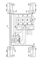
以下、本発明に係る車両の運動状態推定装置を含んだ運動制御装置の一実施形態について図面を参照しつつ説明する。図1は、本発明の実施形態に運動制御装置10を搭載した車両の概略構成を示している。この車両は、駆動輪である前2輪(左前輪FL及び右前輪FR)と、駆動輪である後2輪(左後輪RL及び右後輪RR)を備えた4輪駆動(4WD)方式の4輪車両である。
Hereinafter, an embodiment of a motion control device including a vehicle motion state estimation device according to the present invention will be described with reference to the drawings. FIG. 1 shows a schematic configuration of a vehicle in which a
この運動制御装置10は、各車輪にブレーキ液圧による制動力を発生させるためのブレーキ液圧制御装置30を含んで構成されている。
The
ブレーキ液圧制御装置30は、その概略構成を表す図2に示すように、ブレーキペダルBPの操作力に応じたブレーキ液圧を発生するブレーキ液圧発生部32と、各車輪FR,FL,RR,RLにそれぞれ配置されたホイールシリンダWfr,Wfl,Wrr,Wrlに供給するブレーキ液圧をそれぞれ調整可能なFRブレーキ液圧調整部33,FLブレーキ液圧調整部34,RRブレーキ液圧調整部35,RLブレーキ液圧調整部36と、還流ブレーキ液供給部37とを含んで構成されている。
As shown in FIG. 2 showing a schematic configuration, the brake fluid
ブレーキ液圧発生部32は、ブレーキペダルBPの作動により応動するバキュームブースタVBと、同バキュームブースタVBに連結されたマスタシリンダMCとから構成されている。バキュームブースタVBは、図示しないエンジンの吸気管内の空気圧力(負圧)を利用してブレーキペダルBPの操作力を所定の割合で助勢し同助勢された操作力をマスタシリンダMCに伝達するようになっている。
The brake fluid
マスタシリンダMCは、第1ポート、及び第2ポートからなる2系統の出力ポートを有していて、リザーバRSからのブレーキ液の供給を受けて、前記助勢された操作力に応じた第1マスタシリンダ液圧を第1ポートから発生するようになっているとともに、同第1マスタシリンダ液圧と略同一の液圧である前記助勢された操作力に応じた第2マスタシリンダ液圧を第2ポートから発生するようになっている。これらマスタシリンダMC及びバキュームブースタVBの構成及び作動は周知であるので、ここではそれらの詳細な説明を省略する。このようにして、マスタシリンダMC及びバキュームブースタVBは、ブレーキペダルBPの操作力に応じた第1マスタシリンダ液圧及び第2マスタシリンダ液圧をそれぞれ発生するようになっている。 The master cylinder MC has two output ports including a first port and a second port. The master cylinder MC receives the supply of brake fluid from the reservoir RS and responds to the assisted operating force by the first master. A cylinder hydraulic pressure is generated from the first port, and a second master cylinder hydraulic pressure corresponding to the assisted operating force, which is substantially the same hydraulic pressure as the first master cylinder hydraulic pressure, is supplied to the second port. It comes from the port. Since the configurations and operations of the master cylinder MC and the vacuum booster VB are well known, a detailed description thereof will be omitted here. Thus, the master cylinder MC and the vacuum booster VB generate the first master cylinder hydraulic pressure and the second master cylinder hydraulic pressure in accordance with the operating force of the brake pedal BP, respectively.
マスタシリンダMCの第1ポートは、FRブレーキ液圧調整部33の上流側及びFLブレーキ液圧調整部34の上流側の各々と接続されている。同様に、マスタシリンダMCの第2ポートは、RRブレーキ液圧調整部35の上流側及びRLブレーキ液圧調整部36の上流側の各々と接続されている。これにより、FRブレーキ液圧調整部33の上流部及びFLブレーキ液圧調整部34の上流部の各々には、第1マスタシリンダ液圧が供給されるとともに、RRブレーキ液圧調整部35の上流部及びRLブレーキ液圧調整部36の上流部の各々には、第2マスタシリンダ液圧が供給されるようになっている。
The first port of the master cylinder MC is connected to each of the upstream side of the FR brake fluid
FRブレーキ液圧調整部33は、2ポート2位置切換型の常開電磁開閉弁である増圧弁PUfrと、2ポート2位置切換型の常閉電磁開閉弁である減圧弁PDfrとから構成されており、増圧弁PUfrは、図2に示す第1の位置(非励磁状態における位置)にあるときFRブレーキ液圧調整部33の上流部とホイールシリンダWfrとを連通するとともに、第2の位置(励磁状態における位置)にあるときFRブレーキ液圧調整部33の上流部とホイールシリンダWfrとの連通を遮断するようになっている。減圧弁PDfrは、図2に示す第1の位置(非励磁状態における位置)にあるときホイールシリンダWfrとリザーバRSfとの連通を遮断するとともに、第2の位置(励磁状態における位置)にあるときホイールシリンダWfrとリザーバRSfとを連通するようになっている。
The FR brake fluid
これにより、ホイールシリンダWfr内のブレーキ液圧は、増圧弁PUfr及び減圧弁PDfrが共に第1の位置にあるときホイールシリンダWfr内にFRブレーキ液圧調整部33の上流部の液圧が供給されることにより増圧され、増圧弁PUfrが第2の位置にあり且つ減圧弁PDfrが第1の位置にあるときFRブレーキ液圧調整部33の上流部の液圧に拘わらずその時点の液圧に保持されるとともに、増圧弁PUfr及び減圧弁PDfrが共に第2の位置にあるときホイールシリンダWfr内のブレーキ液がリザーバRSfに還流されることにより減圧されるようになっている。
As a result, the brake fluid pressure in the wheel cylinder Wfr is supplied to the wheel cylinder Wfr upstream of the FR brake fluid
また、増圧弁PUfrにはブレーキ液のホイールシリンダWfr側からFRブレーキ液圧調整部33の上流部への一方向の流れのみを許容するチェック弁CV1が並列に配設されており、これにより、操作されているブレーキペダルBPが開放されたときホイールシリンダWfr内のブレーキ液圧が迅速に減圧されるようになっている。
Further, a check valve CV1 that allows only one-way flow of brake fluid from the wheel cylinder Wfr side to the upstream portion of the FR brake fluid
同様に、FLブレーキ液圧調整部34,RRブレーキ液圧調整部35及びRLブレーキ液圧調整部36は、それぞれ、増圧弁PUfl及び減圧弁PDfl,増圧弁PUrr及び減圧弁PDrr,増圧弁PUrl及び減圧弁PDrlから構成されており、これらの各増圧弁及び各減圧弁の位置が制御されることにより、ホイールシリンダWfl,ホイールシリンダWrr及びホイールシリンダWrl内のブレーキ液圧をそれぞれ増圧、保持、減圧できるようになっている。また、増圧弁PUfl,PUrr及びPUrlの各々にも、上記チェック弁CV1と同様の機能を達成し得るチェック弁CV2,CV3及びCV4がそれぞれ並列に配設されている。
Similarly, the FL brake hydraulic
還流ブレーキ液供給部37は、直流モータMTと、同モータMTにより同時に駆動される2つの液圧ポンプHPf,HPrを含んでいる。液圧ポンプHPfは、減圧弁PDfr,PDflから還流されてきたリザーバRSf内のブレーキ液を汲み上げ、同汲み上げたブレーキ液をチェック弁CV5,CV6を介してFRブレーキ液圧調整部33及びFLブレーキ液圧調整部34の上流部に供給するようになっている。
The reflux brake fluid supply unit 37 includes a DC motor MT and two hydraulic pumps HPf and HPr that are simultaneously driven by the motor MT. The hydraulic pump HPf pumps up the brake fluid in the reservoir RSf that has been recirculated from the pressure reducing valves PDfr and PDfl, and the pumped brake fluid passes through the check valves CV5 and CV6 to the FR brake fluid
同様に、液圧ポンプHPrは、減圧弁PDrr,PDrlから還流されてきたリザーバRSr内のブレーキ液を汲み上げ、同汲み上げたブレーキ液をチェック弁CV7,CV8を介してRRブレーキ液圧調整部35及びRLブレーキ液圧調整部36の上流部に供給するようになっている。なお、液圧ポンプHPf,HPrの吐出圧の脈動を低減するため、チェック弁CV5及びCV6の間の液圧回路、及びチェック弁CV7及びCV8の間の液圧回路には、それぞれ、ダンパDMf,DMrが配設されている。
Similarly, the hydraulic pump HPr pumps up the brake fluid in the reservoir RSr that has been refluxed from the pressure reducing valves PDrr and PDrl, and the pumped brake fluid through the check valves CV7 and CV8, and the RR brake fluid
以上、説明した構成により、ブレーキ液圧制御装置30は、全ての電磁弁が第1の位置にあるときブレーキペダルBPの操作力に応じたブレーキ液圧を各ホイールシリンダに供給できるようになっている。また、この状態において、例えば、増圧弁PUrr及び減圧弁PDrrをそれぞれ制御することにより、ホイールシリンダWrr内のブレーキ液圧のみを所定量だけ減圧することができるようになっている。即ち、ブレーキ液圧制御装置30は、各車輪のホイールシリンダ内のブレーキ液圧をそれぞれ独立してブレーキペダルBPの操作力に応じたブレーキ液圧から減圧できるようになっている。
As described above, the brake hydraulic
再び、図1を参照すると、運動制御装置10は、対応する車輪の回転速度に応じた周波数を有する信号を出力する磁気ピックアップ式(コイル式)の車輪速度センサ41fr,41fl,41rr,41rlと、ブレーキペダルBPの操作の有無に応じてオン状態又はオフ状態になるSTP信号を出力するブレーキスイッチ42と、対応するタイヤの空気圧を直接検出し、タイヤ空気圧Pfr,Pfl,Prr,Prlを示す信号を出力する圧力センサからなるタイヤ空気圧センサ43fr,43fl,43rr,43rl(タイヤ空気圧取得手段)を備えている。なお、車輪速度センサは、半導体式のセンサ(特に、磁気抵抗素子(MR素子)を利用したセンサ)であってもよい。
Referring to FIG. 1 again, the
電気式制御装置50は、互いにバスで接続された、CPU51、CPU51が実行するルーチン(プログラム)、テーブル(ルックアップテーブル、マップ)、定数等を予め記憶したROM52、CPU51が必要に応じてデータを一時的に格納するRAM53、電源が投入された状態でデータを格納するとともに同格納したデータを電源が遮断されている間も保持するバックアップRAM54、及びADコンバータを含むインターフェース55等からなるマイクロコンピュータである。
The
インターフェース55は、前記センサ等41〜43と接続され、CPU51にセンサ等41〜43からの信号を供給するとともに、同CPU51の指示に応じてブレーキ液圧制御装置30の各電磁弁、及びモータMTに駆動信号を送出するようになっている。
The
(制動力配分制御の概要)
次に、上記のように構成された本発明の実施形態に係る運動状態推定装置を含んだ運動制御装置10(以下、「本装置」と云うこともある。)が実行する制動力配分制御(以下、「BFD制御」とも称呼する。)について説明する。
(Outline of braking force distribution control)
Next, braking force distribution control (hereinafter also referred to as “the present apparatus”) executed by the motion control apparatus 10 (hereinafter also referred to as “the present apparatus”) including the motion state estimation apparatus according to the embodiment of the present invention configured as described above. Hereinafter, this will also be referred to as “BFD control”.
車両が直進状態から旋回状態に移行する際(以下、「旋回初期状態にある」とも称呼する。)、運転者によるブレーキ操作が行われていると、車体には、同ブレーキ操作による車両の減速度(前後加速度)に応じた慣性力が車体前方に向けて働くと同時に、旋回に伴って発生する横加速度に応じた慣性力(即ち、遠心力)が旋回方向外側に向けて働く。これにより、車両の後側の車輪が受ける荷重が上記車体前方に向けて働く慣性力の大きさに応じた分だけ減少することで同後側の車輪(タイヤ)が路面から受け得る最大摩擦力が減少する。 When the vehicle transitions from the straight traveling state to the turning state (hereinafter also referred to as “in the initial turning state”), if the driver performs a braking operation, the vehicle body is reduced by the braking operation. Inertial force according to the speed (longitudinal acceleration) works toward the front of the vehicle body, and at the same time, inertial force (that is, centrifugal force) according to the lateral acceleration generated along with the turning works outward in the turning direction. As a result, the maximum frictional force that the rear wheel (tire) can receive from the road surface by reducing the load received by the rear wheel of the vehicle by an amount corresponding to the magnitude of the inertial force acting toward the front of the vehicle body. Decrease.
この結果、上記ブレーキ操作に基づく減速度(従って、慣性力)の大きさ、及び上記遠心力の大きさによっては、同遠心力の大きさが、車両の後側の車輪が路面から受け得る最大摩擦力における旋回方向内側方向の成分の大きさよりも大きくなる場合がある。この場合、車両の後側の車輪が旋回方向外側に向けて滑り出し、この結果、車両にスピン傾向が発生する。 As a result, depending on the magnitude of the deceleration (accordingly, the inertial force) based on the brake operation and the magnitude of the centrifugal force, the magnitude of the centrifugal force is the maximum that the rear wheel of the vehicle can receive from the road surface. In some cases, the friction force may be larger than the magnitude of the component in the direction of the turning direction. In this case, the rear wheel of the vehicle starts to slide outward in the turning direction, and as a result, a spin tendency is generated in the vehicle.
係るスピン傾向の発生を未然に抑制するためには、旋回方向と反対方向のヨーイングモーメントを強制的に車両に与えることが必要である。また、旋回方向と反対方向のヨーイングモーメント(スピン抑制ヨーイングモーメントM)を強制的に車両に与えるためには、車両の旋回方向を特定し、旋回方向内側の車輪に働く制動力(の総和)が旋回方向外側の車輪に働く制動力(の総和)よりも小さくなるように、車両左側の車輪に働く制動力(の総和)と同車両右側の車輪に働く制動力(の総和)との間に差を与えればよい。 In order to suppress the occurrence of such a spin tendency, it is necessary to forcibly give the vehicle a yawing moment in the direction opposite to the turning direction. In addition, in order to forcibly give the vehicle a yawing moment (spin suppression yawing moment M) opposite to the turning direction, the turning direction of the vehicle is specified and the braking force (total) acting on the wheels inside the turning direction is determined. Between the braking force acting on the wheel on the left side of the vehicle (sum) and the braking force acting on the wheel on the right side of the vehicle (sum of the total) so that it is smaller than the braking force acting on the wheel on the outer side in the turning direction. What is necessary is just to give a difference.
ここで、車両の旋回方向は、タイヤ空気圧の変化に基づいて特定することができる。即ち、車両が旋回初期状態にあると、車体には、上述したように遠心力が旋回方向外側に向けて作用開始する。従って、旋回初期において、旋回方向外側の車輪のタイヤ空気圧が上記遠心力の大きさに応じて増加するとともに旋回方向内側の車輪のタイヤ空気圧が同遠心力の大きさに応じて減少する。 Here, the turning direction of the vehicle can be specified based on a change in tire air pressure. That is, when the vehicle is in the initial turning state, the centrifugal force starts to act on the vehicle body toward the outside in the turning direction as described above. Therefore, at the beginning of turning, the tire air pressure of the wheels on the outer side in the turning direction increases in accordance with the magnitude of the centrifugal force, and the tire air pressure of the wheels on the inner side in the turning direction decreases in accordance with the magnitude of the centrifugal force.
従って、車両左側の車輪のタイヤ空気圧と車両右側の車輪のタイヤ空気圧の何れか一方が増加していて他方が減少していることは、車両がタイヤ空気圧が減少している側へ旋回する旋回初期状態にあることを意味する。これにより、車両の旋回方向が特定され得る。 Therefore, when either the tire pressure of the left wheel of the vehicle or the tire pressure of the right wheel of the vehicle is increasing and the other is decreasing, the vehicle is turning to the side where the tire pressure is decreasing. It means being in a state. Thereby, the turning direction of the vehicle can be specified.
また、上記スピン傾向の程度は上記遠心力の大きさに応じて増大する。他方、上記遠心力が大きくなるほど、車両左側及び右側の車輪のタイヤ空気圧の各変化量(各変化勾配)が大きくなる。即ち、上記スピン傾向の程度は、車両左側及び右側の車輪のタイヤ空気圧の各変化量(各変化勾配)が大きくなるほど大きくなる。 The degree of the spin tendency increases with the magnitude of the centrifugal force. On the other hand, as the centrifugal force increases, the change amounts (change gradients) of the tire air pressure of the left and right wheels of the vehicle increase. That is, the degree of the spin tendency increases as the change amounts (change gradients) of the tire air pressure of the left and right wheels of the vehicle increase.
以上のことから、本装置は、タイヤ空気圧センサ43**から得られるタイヤ空気圧P**を車輪毎に逐次(例えば、6msec毎に)監視するとともに、タイヤ空気圧変化量ΔP**(今回値から前回値を減じた値)を車輪毎に逐次算出する。なお、各種変数等の末尾に付された「**」は、同各種変数等が各車輪FR等のいずれに関するものであるかを示すために同各種変数等の末尾に付される「fl」,「fr」等の包括表記であって、例えば、タイヤ空気圧センサ43**は、右前輪タイヤ空気圧センサ43fr,
左前輪タイヤ空気圧センサ43fl, 右後輪タイヤ空気圧センサ43rr, 左後輪タイヤ空気圧センサ43rlを包括的に示している。
From the above, this apparatus monitors the tire air pressure P ** obtained from the tire air pressure sensor 43 ** sequentially for each wheel (for example, every 6 msec), and changes the tire air pressure change ΔP ** (from the current value). The value obtained by subtracting the previous value is sequentially calculated for each wheel. In addition, “**” appended to the end of various variables etc. “fl” added to the end of the various variables etc. to indicate which of the various wheels FR, etc. , “Fr” and the like, for example, the tire pressure sensor 43 ** includes a right front wheel tire pressure sensor 43fr,
A left front wheel tire pressure sensor 43fl, a right rear wheel tire pressure sensor 43rr, and a left rear wheel tire pressure sensor 43rl are shown in a comprehensive manner.
そして、本装置は、STP信号がON状態となっていて、且つ、車両左側の車輪のタイヤ空気圧変化量(本例では、ΔPflとΔPrlの平均値(平均左側タイヤ空気圧変化量ΔPlemean))と、車両右側の車輪のタイヤ空気圧変化量(本例では、ΔPfrとΔPrrの平均値(平均右側タイヤ空気圧変化量ΔPrimean))のうちの一方がBFD制御開始判定用基準値ΔPthbfd(正の一定値)よりも大きくて他方が値「−ΔPthbfd」よりも小さいとき、BFD制御を開始する。具体的には、本装置は、タイヤ空気圧変化量が値「−ΔPthbfd」よりも小さい側(即ち、旋回方向内側)の後輪のブレーキ液圧を保持するとともに、STP信号がON状態からOFF状態に変更されるまで同ブレーキ液圧の保持を継続する。 In this device, the STP signal is in the ON state, and the tire air pressure change amount of the left wheel of the vehicle (in this example, the average value of ΔPfl and ΔPrl (average left tire air pressure change amount ΔPlemean)), One of the tire air pressure change amounts of the wheels on the right side of the vehicle (in this example, the average value of ΔPfr and ΔPrr (average right tire air pressure change amount ΔPrimean)) is based on the reference value ΔPthbfd (positive constant value) for BFD control start determination Is larger and the other is smaller than the value “−ΔPthbfd”, the BFD control is started. Specifically, this device maintains the brake fluid pressure on the rear wheel whose tire air pressure change is smaller than the value “−ΔPthbfd” (that is, the inside in the turning direction), and the STP signal changes from the ON state to the OFF state. The brake fluid pressure is maintained until changed to.
例えば、図3に示すように、車両が左側へ旋回する旋回初期状態にある場合、車両右側の車輪のタイヤ空気圧が増加するとともに車両左側の車輪のタイヤ空気圧が減少する。このとき、STP信号がON状態となっていて、「平均右側タイヤ空気圧変化量ΔPrimean>ΔPthbfd」、及び「平均左側タイヤ空気圧変化量ΔPlemean<−ΔPthbfd」が共に成立していると、本装置は、その後においてSTP信号がOFF状態になるまで左後輪RLのブレーキ液圧を保持する。 For example, as shown in FIG. 3, when the vehicle is in an initial turning state in which the vehicle turns to the left side, the tire air pressure of the wheel on the right side of the vehicle increases and the tire air pressure of the wheel on the left side of the vehicle decreases. At this time, if the STP signal is in the ON state and both “average right tire pressure change ΔPrimean> ΔPthbfd” and “average left tire air pressure change ΔPlemean <−ΔPthbfd” are both established, Thereafter, the brake fluid pressure of the left rear wheel RL is maintained until the STP signal is turned off.
これにより、上記ブレーキ液圧の保持が開始された後において運転者のブレーキ操作によるブレーキ液圧が更に増大すると、左後輪RLに働く制動力が右後輪RRに働く制動力よりも小さくなり、図3に示すように後2輪に働く制動力の間に差が生じる。この結果、車両の重心Gのまわりに車両上方から見て時計まわりのスピン抑制ヨーイングモーメントMが発生してスピン傾向の発生が未然に抑制される。 As a result, when the brake fluid pressure due to the driver's brake operation further increases after the holding of the brake fluid pressure is started, the braking force acting on the left rear wheel RL becomes smaller than the braking force acting on the right rear wheel RR. As shown in FIG. 3, there is a difference between the braking forces acting on the rear two wheels. As a result, a clockwise spin suppression yawing moment M is generated around the center of gravity G of the vehicle as viewed from above the vehicle, and the occurrence of a spin tendency is suppressed in advance.
以上のように、本装置は、「横加速度を表す値」としての平均右側タイヤ空気圧変化量ΔPrimean、及び平均左側タイヤ空気圧変化量ΔPlemeanに基づいて車両の旋回状態を推定し、係る推定結果に基づいてBFD制御を開始・実行する。以上が、本装置によるBFD制御の概要である。 As described above, this apparatus estimates the turning state of the vehicle based on the average right tire pressure change amount ΔPrimean and the average left tire air pressure change amount ΔPlemean as “values representing lateral acceleration”, and based on the estimation results. To start and execute BFD control. The above is the outline of the BFD control by this apparatus.
(アンチスキッド制御の概要)
次に、本装置が実行するアンチスキッド制御(以下、「ABS制御」とも称呼する。)について説明する。本装置は、後述するように車両が走行している路面が氷上路を含む所定の摩擦係数よりも小さい摩擦係数を有する低μ路面である(可能性がある)か、アスファルト路を含む同所定の摩擦係数以上の摩擦係数を有する通常路面であるか、を判定するとともに、同判定結果に応じて通常路面用のABS制御と、低μ路面用のABS制御の何れかを選択的に実行する。通常路面用ABS制御と低μ路面用ABS制御とは制御態様(即ち、制御の開始条件、及び、ブレーキ液圧の減圧・保持・増圧パターン)が異なる。
(Outline of anti-skid control)
Next, the anti-skid control (hereinafter also referred to as “ABS control”) executed by the present apparatus will be described. As will be described later, this apparatus is a low-μ road surface having a friction coefficient smaller than a predetermined friction coefficient including an icy road (possibly) or a predetermined road surface including an asphalt road. It is determined whether the road surface is a normal road surface having a friction coefficient equal to or greater than the friction coefficient, and either the normal road surface ABS control or the low μ road surface ABS control is selectively executed according to the determination result. . The normal road surface ABS control and the low μ road surface ABS control are different in control mode (that is, the control start condition and the brake fluid pressure decreasing / holding / increasing pattern).
<通常路面用ABS制御の概要>
以下、先ず、通常路面用ABS制御について説明する。通常路面用ABS制御は、所望の減速度を維持することを主目的とする制御である。本装置は、ABS制御を実行するにあたり、車輪速度センサ41**の出力に基づいて車輪速度Vw**を車輪毎に逐次計算するとともに、同車輪速度Vw**の時間的変化率から車輪加速度DVw**を車輪毎に逐次計算する。
<Outline of normal road surface ABS control>
Hereinafter, first, the normal road surface ABS control will be described. The normal road surface ABS control is a control whose main purpose is to maintain a desired deceleration. When executing the ABS control, this device sequentially calculates the wheel speed Vw ** for each wheel based on the output of the wheel speed sensor 41 **, and calculates the wheel acceleration from the temporal change rate of the wheel speed Vw **. DVw ** is calculated sequentially for each wheel.
他方、本装置は、車両の推定車体速度Vsoを下記(1)式に従って逐次求める。下記(1)式において、関数maxは各引数のうちの最大値を採る関数である。また、値gradlimitは車両が減速する際に実際に達成し得る車体速度の単位時間あたりの最大減少量(車体速度の最大減少勾配)であり、本例では定数である。なお、本装置が車両が走行している路面の路面摩擦係数を逐次取得する手段を備えている場合、同取得された路面摩擦係数に応じて値gradlimitを変更するように構成してもよい。Δtは、CPU51による推定車体速度Vsoの演算周期である。
On the other hand, the present apparatus sequentially obtains the estimated vehicle body speed Vso of the vehicle according to the following equation (1). In the following equation (1), the function max is a function that takes the maximum value of each argument. Further, the value gradlimit is the maximum reduction amount of vehicle body speed per unit time that can actually be achieved when the vehicle decelerates (maximum reduction gradient of vehicle body speed), and is a constant in this example. In addition, when this apparatus is provided with the means which acquires the road surface friction coefficient of the road surface where the vehicle is drive | working sequentially, you may comprise so that value gradlimit may be changed according to the acquired road surface friction coefficient. Δt is a calculation cycle of the estimated vehicle body speed Vso by the
Vso=max(max(Vw**),Vso-gradlimit・Δt) ・・・(1) Vso = max (max (Vw **), Vso-gradlimit · Δt) (1)
上記(1)式から理解できるように、今回の推定車体速度Vsoは、今回の最大車輪速度max(Vw**)と、前回の推定車体速度Vsoから値gradlimitにΔtを乗じた値を減じた値とのうちの大きい方の値として求められる。 As can be understood from the above equation (1), the current estimated vehicle speed Vso is the current maximum wheel speed max (Vw **) and the value obtained by multiplying the previous estimated vehicle speed Vso by the value gradlimit by Δt. It is determined as the larger of the values.
そして、本装置は、後述するように、車両が走行している路面が通常路面であるとの判定を行っている場合、下記(2)式、及び下記(3)式が成立したとき、車輪**について通常路面用ABS制御を開始する。即ち、下記(2)式、及び下記(3)式は、通常路面用のABS制御の開始条件(の一部)を表している。 Then, as will be described later, when it is determined that the road surface on which the vehicle is traveling is a normal road surface, when the following equation (2) and the following equation (3) are satisfied, The normal road surface ABS control is started for **. That is, the following formula (2) and the following formula (3) represent the start condition (part of) of the ABS control for the normal road surface.
Vso-Vw** > ΔVwrefnorm ・・・(2)
DVw** < DVwrefnorm ・・・(3)
Vso-Vw **> ΔVwrefnorm (2)
DVw ** <DVwrefnorm (3)
上記(2)式において、「Vso-Vw**」は車輪**のスリップ量を表す。ΔVwrefnormは通常路面用のABS制御開始判定用スリップ量基準値(正の一定値)である。上記(3)式において、DVwrefnormは通常路面用のABS制御開始判定用車輪加速度基準値(負の一定値)である。 In the above equation (2), “Vso−Vw **” represents the slip amount of the wheel **. ΔVwrefnorm is a slip amount reference value (positive constant value) for ABS control start determination for a normal road surface. In the above equation (3), DVwrefnorm is a wheel acceleration reference value (negative constant value) for ABS control start determination for a normal road surface.
通常路面用ABS制御の開始条件が成立すると、本装置は、図4に示すように通常路面用ABS制御を直ちに開始・実行する。図4(a)は、通常路面用ABS制御(の一サイクル)が時刻t0にて開始されてから時刻t8にて終了されるまでの間における同ABS制御が実行される対象となる車輪(即ち、時刻t0にて上記通常路面用のABS制御の開始条件が成立した車輪**。以下、「制御対象車輪」と称呼する。)についての基本的なブレーキ液圧制御モード(増圧モード、保持モード、及び減圧モード)の変化を示したタイムチャートである。図4(b)は、上記ブレーキ液圧制御モードの変化に応じた制御対象車輪についてのブレーキ液圧の変化を示したタイムチャートである。
When the start condition for the normal road surface ABS control is satisfied, the apparatus immediately starts and executes the normal road surface ABS control as shown in FIG. FIG. 4 (a) shows a wheel (i.e., the ABS control for which normal ABS control (one cycle) is started at time t0 until the ABS control is completed at time t8). The basic brake fluid pressure control mode (pressure increasing mode, holding) for the wheel for which the above-mentioned conditions for starting the ABS control for the normal road surface are satisfied at
図4(a),(b)から理解できるように、本装置は、制御対象車輪についてのブレーキ液圧制御モードを、時刻t0にて増圧モード(ABS制御が実行されていない状態)から減圧モードへと切換えるとともに、同時点以降、所定の通常路面用減圧時間T1が経過する時刻t1までの間、減圧モードに維持した後、同時刻t1にて減圧モードから保持モードへと切換える。これにより、制御対象車輪についてのブレーキ液圧は、時刻t0以降時刻t1までの間、低下し続けるとともに、時刻t1以降、同時点での値に維持される。この結果、制御対象車輪の車輪加速度DVw**が増大することで、時刻t2にて同車輪加速度DVw**の値が負の値から正の値に変化したものと仮定する。 As can be understood from FIGS. 4 (a) and 4 (b), this apparatus reduces the brake fluid pressure control mode for the wheel to be controlled from the pressure increase mode (the state in which ABS control is not executed) at time t0. In addition to switching to the mode, after maintaining at the time t1 when a predetermined normal road surface pressure reduction time T1 elapses after the same point, the pressure reduction mode is switched to the holding mode at the same time t1. As a result, the brake fluid pressure for the wheel to be controlled continues to decrease from time t0 to time t1, and is maintained at a value at the same point after time t1. As a result, it is assumed that the wheel acceleration DVw ** of the wheel to be controlled increases, so that the value of the wheel acceleration DVw ** changes from a negative value to a positive value at time t2.
本装置は、時刻t2になると、制御対象車輪についてのブレーキ液圧制御モードを、同時点にて保持モードから増圧モードへと切換えるとともに、同時点以降、所定の通常路面用増圧時間T2が経過する時刻t3までの間、増圧モードに維持するとともに、時刻t3にて増圧モードから保持モードへと切換え、同時点以降、所定の通常路面用保持時間T3が経過する時刻t4までの間、保持モードに維持する。これにより、制御対象車輪についてのブレーキ液圧は、時刻t2以降時刻t3までの間、増大し続けるとともに、時刻t3以降時刻t4までの間、時刻t3での値に維持される。 At time t2, this apparatus switches the brake fluid pressure control mode for the wheel to be controlled from the holding mode to the pressure increasing mode at the same time, and after that time, a predetermined normal road surface pressure increasing time T2 is set. The pressure-increasing mode is maintained until time t3, and the pressure-increasing mode is switched from the pressure-increasing mode to time t3 at time t3. , Keep in hold mode. As a result, the brake fluid pressure for the wheel to be controlled continues to increase from time t2 to time t3, and is maintained at the value at time t3 from time t3 to time t4.
本装置は、時刻t4以降も、時刻t4〜時刻t6、及び時刻t6〜時刻t8において、上述した時刻t2〜時刻t4と同様、制御対象車輪についてのブレーキ液圧制御モードを上記通常路面用増圧時間T2に渡って増圧モードに維持するとともにその後上記通常路面用保持時間T3に渡って保持モードに維持する処理を行い(即ち、時刻t2〜時刻t4までの処理を計3回繰り返し)、時刻t8にて、制御対象車輪についてのブレーキ液圧制御モードを保持モードから増圧モード(ABS制御が実行されていない状態)へと切換えることで通常路面用のABS制御(の一サイクル)を終了する。 After time t4, this device also sets the brake fluid pressure control mode for the wheel to be controlled to the normal road surface pressure increase at time t4 to time t6 and time t6 to time t8, similarly to the time t2 to time t4 described above. A process of maintaining the pressure increasing mode for the time T2 and maintaining the holding mode for the normal road surface holding time T3 is performed (that is, the processes from the time t2 to the time t4 are repeated three times in total). At t8, the brake fluid pressure control mode for the wheel to be controlled is switched from the holding mode to the pressure increasing mode (a state in which the ABS control is not executed), thereby completing the ABS control (one cycle) for the normal road surface. .
上記通常路面用減圧時間T1、通常路面用増圧時間T2、及び通常路面用保持時間T3は、上記(2)式、及び上記(3)式に示した通常路面用ABS制御の開始条件が成立した時点における車輪**の車輪加速度DVw**の変化速度(時間微分値)DDVw**に応じて設定される。 The normal road surface pressure reduction time T1, the normal road surface pressure increase time T2, and the normal road surface holding time T3 satisfy the start conditions of the normal road surface ABS control shown in the above equations (2) and (3). It is set according to the change speed (time differential value) DDVw ** of the wheel acceleration DVw ** of the wheel ** at the time of the above.
なお、時刻t0以降における制御対象車輪の車輪加速度DVw**の増大速度が大きくて、上記時刻t2(即ち、制御対象車輪の車輪加速度DVw**の値が負の値から正の値に変化する時点)が上記時刻t1(即ち、時刻t0から上記通常路面用減圧時間T1が経過する時点)よりも前の時点となる場合、本装置は、制御対象車輪についてのブレーキ液圧制御モードを同時刻t2にて直ちに減圧モードから増圧モードに切換え、同時点以降、図4に示した時刻t2〜時刻t8までの処理を行う。 Note that the increase speed of the wheel acceleration DVw ** of the control target wheel after time t0 is large, and the value of the time t2 (that is, the wheel acceleration DVw ** of the control target wheel changes from a negative value to a positive value). Time) is the time before the time t1 (that is, the time when the normal road pressure reduction time T1 elapses from the time t0), the device sets the brake fluid pressure control mode for the wheel to be controlled at the same time. At t2, the pressure reduction mode is immediately switched to the pressure increase mode, and processing from time t2 to time t8 shown in FIG.
一方、時刻t0以降における制御対象車輪の車輪加速度DVw**の増大速度が小さくて(或いは、車輪加速度DVw**が増大せず)、時刻t1においても上記(2)式、及び上記(3)式に示した通常路面用のABS制御の開始条件がなお成立している場合、同時点を新たな時刻t0として設定し直し、同新たな時刻t0以降、再び、図4に示した時刻t0〜時刻t8までの処理を実行する。これにより、最初に通常路面用のABS制御の開始条件が成立した時点以降、減圧モードが上記通常路面用減圧時間T1の2倍の時間に渡って継続して実行されることになる。以上が、通常路面用ABS制御の概要である。 On the other hand, the increase speed of the wheel acceleration DVw ** of the wheel to be controlled after time t0 is small (or the wheel acceleration DVw ** does not increase), and the above equation (2) and (3) also at time t1. If the start condition for the normal road surface ABS control shown in the equation is still satisfied, the simultaneous point is reset as a new time t0, and after the new time t0, the time t0 shown in FIG. Processing up to time t8 is executed. As a result, the decompression mode is continuously executed over a period twice as long as the normal road surface decompression time T1 after the initial condition for starting the normal road surface ABS control is satisfied. The above is the outline of the normal road surface ABS control.
<低μ路面用ABS制御の概要>
次に、低μ路面用ABS制御について説明する。低μ路面用ABS制御は、車輪速度を回復させることを主目的とする制御である。図1に示した車両は4WD方式の車両であるから、総ての車輪が駆動系統を介して互いに連結されている。従って、低μ路面において過度のブレーキ操作が実行されると、総ての車輪(駆動輪)が略均一にスリップを開始・継続する傾向がある。即ち、総ての車輪速度Vw**が略同一の勾配をもって低下していく傾向がある。
<Outline of ABS control for low μ road surface>
Next, low μ road surface ABS control will be described. The low μ road surface ABS control is a control whose main purpose is to recover the wheel speed. Since the vehicle shown in FIG. 1 is a 4WD type vehicle, all the wheels are connected to each other via a drive system. Therefore, when an excessive braking operation is performed on the low μ road surface, all the wheels (drive wheels) tend to start and continue slipping substantially uniformly. That is, all wheel speeds Vw ** tend to decrease with substantially the same gradient.
よって、この場合、車輪速度差が発生し難くなって、各車輪のスリップ量「Vso-Vw**」が前記通常路面用のABS制御開始判定用スリップ量基準値ΔVwrefnormを超えず(即ち、通常路面用ABS制御の開始条件が成立せず)、この結果、ABS制御が適切なタイミングで開始され難い。従って、この場合、ABS制御の開始条件を同制御が開始され易くなる方向に修正する必要がある。 Therefore, in this case, the wheel speed difference is unlikely to occur, and the slip amount “Vso-Vw **” of each wheel does not exceed the normal road surface ABS control start determination slip amount reference value ΔVwrefnorm (ie, normal As a result, the ABS control is hardly started at an appropriate timing. Therefore, in this case, it is necessary to correct the ABS control start condition so that the control is easily started.
また、低μ路面においては、ABS制御が開始されたとしても、タイヤが路面から受ける増速方向の回転モーメントが小さいことに起因して、一旦低下した車輪の車輪速度がブレーキ液圧の減圧制御に伴って車体速度相当まで回復するまでに比較的長い時間が必要となる。従って、この場合、車両の走行安定性を確保するため、大きい減速度を維持することよりも車輪の車輪速度を回復させることが優先されるべきである。 On the low μ road surface, even if ABS control is started, the wheel speed of the wheel once lowered due to the small rotational moment in the speed increasing direction that the tire receives from the road surface is controlled to reduce the brake fluid pressure. Accordingly, it takes a relatively long time to recover to the vehicle speed. Therefore, in this case, in order to ensure the running stability of the vehicle, priority should be given to restoring the wheel speed of the wheels rather than maintaining a large deceleration.
以上のことから、本装置は、後述するように、車両が走行している路面が低μ路面である(可能性がある)との判定を行っている場合、下記(4)式、及び下記(5)式が成立したとき、車輪**について低μ路面用のABS制御を開始する。即ち、下記(4)式、及び下記(5)式は、低μ路面用ABS制御の開始条件を表している。 From the above, this device, as will be described later, when determining that the road surface on which the vehicle is traveling is a low μ road surface (possibly), When the formula (5) is established, the ABS control for the low μ road surface is started for the wheel **. That is, the following formula (4) and the following formula (5) represent the start conditions of the low μ road surface ABS control.
Vso-Vw** > ΔVwreflow ・・・(4)
DVw** < DVwreflow ・・・(5)
Vso-Vw **> ΔVwreflow (4)
DVw ** <DVwreflow (5)
上記(4)式において、ΔVwreflowは低μ路面用のABS制御開始判定用スリップ量基準値(正の一定値)であって、前記通常路面用のABS制御開始判定用スリップ量基準値ΔVwrefnormよりも小さい値である。上記(5)式において、DVwreflowは低μ路面用のABS制御開始判定用車輪加速度基準値(負の一定値)であって、前記通常路面用のABS制御開始判定用車輪加速度基準値DVwrefnormより大きい値である。これにより、低μ路面用ABS制御の開始条件は、通常路面用ABS制御の開始条件に比してABS制御がより開始され易い条件となる。 In the above equation (4), ΔVwreflow is an ABS control start determination slip amount reference value (positive constant value) for a low μ road surface, which is larger than the ABS control start determination slip amount reference value ΔVwrefnorm for the normal road surface. Small value. In the above formula (5), DVwreflow is a wheel acceleration reference value for ABS control start determination (a constant negative value) for a low μ road surface, and is larger than the ABS acceleration start determination wheel acceleration reference value DVwrefnorm for the normal road surface. Value. Accordingly, the start condition of the low μ road surface ABS control is a condition in which the ABS control is more easily started than the start condition of the normal road surface ABS control.
そして、本装置は、車両が走行している路面が低μ路面である(可能性がある)と判定している場合であって、上記低μ路面用ABS制御の開始条件が成立したとき、先の図4(b)(図5の実線に同じ)に示した通常路面用ABS制御において、図5に破線にて示したように、上記通常路面用減圧時間T1、通常路面用増圧時間T2、及び通常路面用保持時間T3をそれぞれ、低μ路面用減圧時間T1’、低μ路面用増圧時間T2’、及び低μ路面用保持時間T3’に代えた低μ路面用ABS制御を実行する。 And this apparatus is a case where it is determined that the road surface on which the vehicle is traveling is a low μ road surface (possibly), and when the start condition of the low μ road surface ABS control is satisfied, In the normal road surface ABS control shown in FIG. 4B (same as the solid line in FIG. 5), as shown by the broken line in FIG. 5, the normal road surface pressure reduction time T1 and the normal road surface pressure increase time are as described above. Low μ road surface ABS control is performed by replacing T2 and normal road surface holding time T3 with low μ road surface decompression time T1 ′, low μ road surface pressure increasing time T2 ′, and low μ road surface holding time T3 ′, respectively. Execute.
ここで、低μ路面用減圧時間T1’、低μ路面用増圧時間T2’、及び低μ路面用保持時間T3’は、上記(4)式、及び上記(5)式に示した低μ路面用ABS制御の開始条件が成立した時点における車輪**の車輪加速度DVw**の変化速度(時間微分値)DDVw**に応じて設定され、「低μ路面用減圧時間T1’>通常路面用減圧時間T1」、「低μ路面用増圧時間T2’<通常路面用増圧時間T2」、「低μ路面用保持時間T3’>通常路面用保持時間T3」の関係がある。 Here, the low μ road surface pressure reducing time T1 ′, the low μ road surface pressure increasing time T2 ′, and the low μ road surface holding time T3 ′ are the low μ values shown in the above equations (4) and (5). It is set according to the change speed (time differential value) DDVw ** of the wheel acceleration DVw ** of the wheel ** at the time when the road surface ABS control start condition is satisfied, and “low μ road surface decompression time T1 ′> normal road surface” There is a relationship of “decompression time T1”, “low μ road pressure increase time T2 ′ <normal road surface pressure increase time T2”, “low μ road surface retention time T3 ′> normal road surface retention time T3”.
即ち、図5から理解できるように、低μ路面用ABS制御では、通常路面用ABS制御に比して、制御対象車輪のブレーキ液圧の減圧の程度(減圧量、減圧期間)が大きくなって、大きい減速度を維持することよりも車輪の車輪速度を回復させることが優先される。以上が、低μ路面用ABS制御の概要である。 That is, as can be understood from FIG. 5, in the low μ road surface ABS control, the degree of pressure reduction (pressure reduction amount, pressure reduction period) of the brake fluid pressure of the wheel to be controlled is larger than that in the normal road surface ABS control. Priority is given to restoring the wheel speed of the wheel over maintaining a large deceleration. The above is the outline of the low μ road surface ABS control.
<路面判定の概要>
次に、車両が走行している路面が低μ路面である(可能性がある)か否かの判定(路面判定)について説明する。運転者によるブレーキ操作により車輪にスリップが発生している場合における車体の実際の前後加速度(実車体加速度Gact。この場合、負の値。)は路面摩擦係数が大きいほど小さくなる(絶対値が大きくなる)。
<Outline of road judgment>
Next, determination (road surface determination) of whether or not the road surface on which the vehicle is traveling is a low μ road surface (possibly) will be described. The vehicle's actual longitudinal acceleration (actual vehicle acceleration Gact. In this case, a negative value) when the wheel is slipping due to the braking operation by the driver decreases as the road friction coefficient increases (the absolute value increases). Become).
係る観点に着目すると、路面判定のための路面判定用車体加速度基準値DVsoth(正の一定値)として適切な値を設定するとともに、上記(1)式に従って算出される推定車体速度Vsoを時間で微分することで得られる推定車体加速度DVso(この場合、負の値)が値「−DVsoth」よりも大きいとき低μ路面であるとの判定を行い、推定車体加速度DVsoが「−DVsoth」以下であるとき通常路面であるとの判定を行うことが考えられる。 When paying attention to this point of view, an appropriate value is set as the road surface determination vehicle acceleration reference value DVsoth (positive constant value) for road surface determination, and the estimated vehicle speed Vso calculated according to the above equation (1) When the estimated vehicle acceleration DVso (in this case, negative value) obtained by differentiation is greater than the value “−DVsoth”, it is determined that the road surface is low μ, and the estimated vehicle acceleration DVso is less than “−DVsoth”. It may be possible to determine that the road surface is normal.
しかしながら、上述したように、車両が低μ路面を走行中に総ての車輪が略均一にスリップを開始・継続する場合、以下に述べるように路面判定において誤判定がなされる場合がある。図6は、車体速度V0(即ち、車輪速度Vw**=V0)にて低μ路面上を車両が直進走行中において時刻t1にて運転者がブレーキペダルBPの操作を開始した場合におけるSTP信号の変化、車体加速度の変化、車体速度の変化、及び各車輪速度の変化の例を示したタイムチャートである。 However, as described above, when all the wheels start and continue to slip substantially uniformly while the vehicle is traveling on a low μ road surface, an erroneous determination may be made in the road surface determination as described below. FIG. 6 shows an STP signal when the driver starts operating the brake pedal BP at time t1 while the vehicle is traveling straight on the low μ road surface at the vehicle body speed V0 (ie, the wheel speed Vw ** = V0). 6 is a time chart showing an example of changes in vehicle speed, changes in vehicle body acceleration, vehicle speed changes, and wheel speed changes.
図6に示したように、この例においては、時刻t1にて総ての車輪が略均一にスリップを開始し、この結果、総ての車輪速度Vw**が値V0から略同一の勾配をもって低下していくとともに時刻t2にて「0」に達している。なお、時刻t2以降も車両は移動(前進)している。 As shown in FIG. 6, in this example, all the wheels start to slip substantially uniformly at time t1, and as a result, all the wheel speeds Vw ** have substantially the same gradient from the value V0. While decreasing, it reaches “0” at time t2. Note that the vehicle is moving (advancing) after time t2.
この場合、時刻t1以降において最大車輪速度max(Vw**)と車体の実際の速度(実車体速度Vact)との間に差が発生する。これにより、原則的に最大車輪速度max(Vw**)と等しい値として逐次計算される推定車体速度Vsoの変化勾配(即ち、推定車体加速度DVso。負の値)は、実車体速度Vactの変化勾配(即ち、実車体加速度Gact。負の値)よりも小さくなり得る。 In this case, a difference occurs between the maximum wheel speed max (Vw **) and the actual vehicle speed (actual vehicle speed Vact) after time t1. As a result, the gradient of the estimated vehicle speed Vso (that is, the estimated vehicle acceleration DVso, which is negative), which is sequentially calculated as a value equal to the maximum wheel speed max (Vw **) in principle, is the change in the actual vehicle speed Vact. It can be smaller than the gradient (that is, the actual vehicle acceleration Gact, which is a negative value).
この結果、図6に示すように、実車体加速度Gactが値「−DVsoth」よりも大きい場合であっても、推定車体加速度Gactが値「−DVsoth」以下の値として計算される事態が発生し得る。この場合、車両が走行している路面が低μ路面であるにもかかわらず通常路面であるとの誤判定がなされてしまう。このように、係る誤判定は、推定車体加速度DVsoの推定精度が低い場合があることにより発生する。 As a result, as shown in FIG. 6, even when the actual vehicle acceleration Gact is greater than the value “−DVsoth”, a situation occurs in which the estimated vehicle acceleration Gact is calculated as a value equal to or less than the value “−DVsoth”. obtain. In this case, it is erroneously determined that the road surface on which the vehicle is traveling is a normal road surface even though the road surface is a low μ road surface. As described above, the erroneous determination occurs because the estimation accuracy of the estimated vehicle body acceleration DVso may be low.
ところで、実車体加速度Gactの大きさは、タイヤ空気圧の変化に基づいて精度良く推定することができる。即ち、運転者がブレーキ操作を開始すると、車体には、車体前方に向けて実車体加速度Gactに応じた慣性力が働く。従って、ブレーキ操作開始直後において、車両前側の車輪のタイヤ空気圧が上記慣性力の大きさに応じて増加するとともに車両後側の車輪のタイヤ空気圧が同慣性力の大きさに応じて減少する。よって、車両前側の車輪のタイヤ空気圧の変化量(変化勾配)、或いは車両後側の車輪のタイヤ空気圧の変化量(変化勾配)は、実車体加速度Gactの大きさを精度良く表す値となる。 By the way, the magnitude of the actual vehicle body acceleration Gact can be accurately estimated based on a change in tire air pressure. That is, when the driver starts a brake operation, an inertial force according to the actual vehicle acceleration Gact acts on the vehicle body toward the front of the vehicle body. Therefore, immediately after the start of the brake operation, the tire air pressure of the wheel on the front side of the vehicle increases according to the magnitude of the inertia force, and the tire air pressure of the wheel on the rear side of the vehicle decreases according to the magnitude of the inertia force. Therefore, the change amount (change gradient) of the tire air pressure of the wheel on the front side of the vehicle or the change amount (change gradient) of the tire pressure of the wheel on the rear side of the vehicle is a value that accurately represents the magnitude of the actual vehicle body acceleration Gact.
以上のことから、本装置は、実車体加速度Gact(この場合、負の値)が値「−DVsoth」よりも大きいか否かの判定を上記推定車体加速度DVsoに代えてタイヤ空気圧の変化を利用して行う。 From the above, this device uses the change in tire air pressure instead of the estimated vehicle body acceleration DVso to determine whether the actual vehicle body acceleration Gact (in this case, a negative value) is larger than the value “−DVsoth”. And do it.
具体的には、本装置は、上記路面判定用車体加速度基準値DVsothに相当する路面判定用タイヤ空気圧変化量基準値ΔPthabs(正の一定値)を設定する。そして、本装置は、車両前側の車輪のタイヤ空気圧変化量(本例では、ΔPfrとΔPflの平均値(平均前側タイヤ空気圧変化量ΔPfrmean))がΔPthabsよりも大きい場合、或いは、車両後側の車輪のタイヤ空気圧変化量(本例では、ΔPrrとΔPrlの平均値(平均後側タイヤ空気圧変化量ΔPremean))が値「−ΔPthabs」よりも小さい場合、車両が走行している路面が通常路面であると判定する。この場合、上記(2)式、及び上記(3)式に基づく通常路面用のABS制御の開始条件に従ってABS制御の開始判定が実行され、同条件が成立すると通常路面用ABS制御が開始・実行される。 Specifically, this device sets a road surface determination tire air pressure change reference value ΔPthabs (a positive constant value) corresponding to the road surface determination vehicle body acceleration reference value DVsoth. And this device is used when the tire air pressure change amount of the wheel on the front side of the vehicle (in this example, the average value of ΔPfr and ΔPfl (average front side tire air pressure change amount ΔPfrmean)) is larger than ΔPthabs, or the wheel on the rear side of the vehicle Tire pressure change amount (in this example, the average value of ΔPrr and ΔPrl (average rear tire pressure change amount ΔPremean)) is smaller than the value “−ΔPthabs”, the road surface on which the vehicle is traveling is a normal road surface Is determined. In this case, the start determination of the ABS control is executed according to the start condition of the normal road surface ABS control based on the above formula (2) and the above formula (3), and when the same condition is satisfied, the normal road surface ABS control is started and executed. Is done.
一方、平均前側タイヤ空気圧変化量ΔPfrmeanがΔPthabs以下であり、且つ、平均後側タイヤ空気圧変化量ΔPremeanが値「−ΔPthabs」以上である場合、車両が走行している路面が低μ路面である(可能性がある)と判定する。この場合、上記(4)式、及び上記(5)式に基づく低μ路面用のABS制御の開始条件に従ってABS制御の開始判定が実行され、同条件が成立すると低μ路面用ABS制御が開始・実行される。 On the other hand, when the average front tire pressure change ΔPfrmean is equal to or less than ΔPthabs and the average rear tire pressure change ΔPremean is equal to or greater than the value “−ΔPthabs”, the road surface on which the vehicle is traveling is a low μ road surface ( Possible). In this case, the ABS control start determination is executed according to the start condition of the ABS control for the low μ road surface based on the above formula (4) and the above formula (5), and the ABS control for the low μ road surface is started when the condition is satisfied.・ Executed.
なお、車両の通常路面を走行中において運転者が車輪にロック傾向が発生しない程度の弱いブレーキ操作を行う場合においても、「平均前側タイヤ空気圧変化量ΔPfrmean≦ΔPthabs」、及び「平均後側タイヤ空気圧変化量ΔPremean≧−ΔPthabs」が共に成立し、この結果、低μ路面である(可能性がある)との判定がなされる。しかしながら、この場合、車輪にロック傾向が発生していないことから、上記低μ路面用のABS制御の開始条件が成立し得ず、この結果、車両が通常路面を走行中において低μ路面用のABS制御が開始されることはない。 Even when the driver performs a weak braking operation that does not cause a tendency to lock the wheel while traveling on the normal road surface of the vehicle, “average front tire pressure change ΔPfrmean ≦ ΔPthabs” and “average rear tire pressure” “Change amount ΔPremean ≧ −ΔPthabs” is established, and as a result, it is determined that the road surface is low (possibly). However, in this case, since the wheel does not tend to lock, the ABS control start condition for the low μ road surface cannot be established. As a result, the vehicle is traveling on the normal road surface while the vehicle is traveling on the normal road surface. ABS control is never started.
以上のように、本装置は、「前後加速度を表す値」としての平均前側タイヤ空気圧変化量ΔPfrmean、及び平均後側タイヤ空気圧変化量ΔPremeanに基づいて車両の車体前後方向の加速状態を推定し、係る推定結果に基づいて路面判定を実行する。以上が、本装置によるABS制御の概要である。 As described above, this device estimates the acceleration state of the vehicle in the longitudinal direction of the vehicle based on the average front tire pressure change ΔPfrmean and the average rear tire air pressure change ΔPremean as “values representing longitudinal acceleration”, The road surface determination is executed based on the estimation result. The above is the outline of the ABS control by this apparatus.
(実際の作動)
次に、以上のように構成された本発明による運動状態推定装置を含んだ運動制御装置10の実際の作動について、電気式制御装置50のCPU51が実行するルーチンをフローチャートにより示した図7〜図12を参照しながら説明する。なお、図8に示したフローチャートは、「横加速度を表す値」に基づいて車両の旋回状態を推定する運動状態推定手段に対応し、図10に示したフローチャートは、「前後加速度を表す値」に基づいて車両の車体前後方向の加速状態を推定する運動状態推定手段に対応している。
(Actual operation)
Next, FIG. 7 to FIG. 7 are flowcharts showing routines executed by the
CPU51は、図7に示した車輪速度等の算出を行うためのルーチンを所定時間(例えば、6msec)の経過毎に繰り返し実行している。従って、所定のタイミングになると、CPU51はステップ700から処理を開始し、ステップ705に進んで車輪**の車輪速度(車輪**のタイヤの外周の速度)Vw**をそれぞれ算出する。具体的には、CPU51は車輪速度センサ41**の出力信号波形が有する周波数に基づいて車輪速度Vw**をそれぞれ算出する。
The
次いで、CPU51はステップ710に進み、前記車輪速度Vw**と、前回の本ルーチン実行時におけるステップ710にて算出した前回の推定車体速度Vsoと、上記(1)式とに基づいて、今回の推定車体速度Vsoを算出する。次に、CPU51はステップ715に進み、下記(6)式に従って前記車輪速度**の時間微分値である車輪加速度DVw**をそれぞれ算出する。下記(6)式において、Vwb**は前回の本ルーチン実行時におけるステップ705にて算出された前回の車輪速度Vw**であり、Δtは前記所定時間(CPU51の本ルーチンの実行周期)である。
Next, the
DVw**=(Vw**-Vwb**)/Δt ・・・(6) DVw ** = (Vw **-Vwb **) / Δt (6)
次に、CPU51はステップ720に進み、下記(7)式に従って前記車輪加速度DVw**の変化速度DDVw**をそれぞれ算出する。下記(7)式において、DVwb**は前回の本ルーチン実行時におけるステップ715にて算出された前回の車輪加速度DVw**である。
Next, the
DDVw**=(DVw**-DVwb**)/Δt ・・・(7) DDVw ** = (DVw **-DVwb **) / Δt (7)
続いて、CPU51はステップ725に進んで、下記(8)式に従って前記推定車体速度Vsoの時間微分値である推定車体加速度DVsoを算出する。下記(8)式において、Vsobは前回の本ルーチン実行時におけるステップ710にて算出された前回の推定車体速度Vsoである。
Subsequently, the
DVso=(Vso-Vsob)/Δt ・・・(8) DVso = (Vso-Vsob) / Δt (8)
そして、CPU51はステップ730に進み、タイヤ空気圧センサ43**から得られる現時点でのタイヤ空気圧P**を前回のタイヤ空気圧Pb**としてそれぞれ格納した後、ステップ795に進んで本ルーチンを一旦終了する。以降も、CPU51は本ルーチンを繰り返し実行する。
Then, the
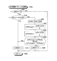
次に、BFD制御の開始・終了判定を行う際の作動について説明する。CPU51は図8に示したルーチンを所定時間(例えば、6msec)の経過毎に繰り返し実行している。従って、所定のタイミングになると、CPU51はステップ800から処理を開始し、ステップ805に進んで、BFD制御実行フラグBFDの値が「0」であるか否かを判定する。ここで、BFD制御実行フラグBFDは、その値が「1」のときBFD制御実行中であることを示し、その値が「0」のときBFD制御実行中でないことを示す。
Next, the operation when the start / end determination of the BFD control is performed will be described. The
いま、BFD制御が実行されていないものとすると、CPU51はステップ805にて「Yes」と判定してステップ810に進み、STP信号がON状態にあるか否か(即ち、運転者によるブレーキ操作が行われているか否か)を判定し、「Yes」と判定する場合、続くステップ815にて先のステップ710にて算出されている推定車体速度Vsoが所定車速Vsoth以上であるか否かを判定する。
If the BFD control is not executed, the
ステップ815でも「Yes」と判定する場合、CPU51はステップ820に進み、タイヤ空気圧センサ43**から検出される現時点でのタイヤ空気圧P**と、先のステップ730にて格納されている前回のタイヤ空気圧Pb**とからタイヤ空気圧変化量ΔP**をそれぞれ求める。
If the determination is “Yes” in
続いて、CPU51はステップ825に進み、ステップ820にて求めた車両右側の車輪のタイヤ空気圧変化量ΔPfr,ΔPrrの平均値である上記平均右側タイヤ空気圧変化量ΔPrimeanを求め、続くステップ830にて、ステップ825と同様にして上記平均左側タイヤ空気圧変化量ΔPlemeanを求める。
Subsequently, the
次に、CPU51はステップ835に進んで、上記平均右側タイヤ空気圧変化量ΔPrimeanが前記BFD制御開始判定用基準値ΔPthbfdよりも大きく、且つ上記平均左側タイヤ空気圧変化量ΔPlemeanが値「−ΔPthbfd」よりも小さいか否かを判定し、「Yes」と判定する場合、ステップ840に進んで旋回フラグLEFTの値を「1」に設定した後、ステップ855に進む。ここで、旋回フラグLEFTは、その値が「1」のとき車両が左側に旋回していることを示し、その値が「0」のとき車両が右側に旋回していることを示す。
Next, the
一方、ステップ835の判定において「No」と判定する場合、CPU51はステップ845に進み、上記ΔPrimeanが上記値「−ΔPthbfd」よりも小さく、且つ上記ΔPlemeanが上記値ΔPthbfdよりも大きいか否かを判定し、「Yes」と判定する場合、ステップ850に進んで旋回フラグLEFTの値を「0」に設定した後、ステップ855に進む。
On the other hand, if the determination in
CPU51はステップ855に進むと、BFD制御実行フラグBFDの値を「0」から「1」に変更し、ステップ895に進んで本ルーチンを一旦終了する。これにより、BFD制御実行フラグBFDの値が「1」に設定されると、後述するルーチンにより旋回フラグLEFTの値に応じた旋回方向に対応するBFD制御が開始される。
When the
このように、ステップ810、815、835からなるAND条件は「車両が左側に旋回している場合におけるBFD制御の開始条件」に対応し、ステップ810、815、845からなるAND条件は「車両が右側に旋回している場合におけるBFD制御の開始条件」に対応している。
Thus, the AND condition consisting of
一方、上記BFD制御の開始条件が成立しない場合(即ち、ステップ810、815、845の何れかで「No」と判定される場合)、CPU51はステップ895に直ちに進んで本ルーチンを一旦終了する。この場合、BFD制御実行フラグBFDの値は「0」に維持されたままであってBFD制御は開始されない。以降、上記BFD制御の開始条件が成立しない限りにおいてCPU51は、ステップ810、815、845の何れかで「No」と判定し、この結果、BFD制御実行フラグBFDの値は「0」に維持され続ける。
On the other hand, when the start condition for the BFD control is not satisfied (that is, when “No” is determined in any of
次に、上記BFD制御の開始条件が成立した場合について説明する。この場合、BFD制御実行フラグBFDの値は「1」になっているから、CPU51はステップ805に進んだとき「No」と判定してステップ865に進み、STP信号がOFF状態となっているか(即ち、運転者によるブレーキ操作が終了したか)、又は、後述するABS制御実行フラグABS**が「1」になっているか(即ち、車輪**についてABS制御が実行中であるか)を判定し、「Yes」と判定する場合、ステップ870に進んでBFD制御実行フラグBFDの値を「1」から「0」に変更する。
Next, a case where the start condition for the BFD control is satisfied will be described. In this case, since the value of the BFD control execution flag BFD is “1”, the
これにより、後述するルーチンによりBFD制御が終了する。即ち、BFD制御実行中においてABS制御が開始されると、同実行中のBFD制御は終了する。換言すれば、ABS制御はBFD制御に優先して実行される。このように、ステップ865の条件は「BFD制御の終了条件」に対応している。
Thereby, BFD control is complete | finished by the routine mentioned later. In other words, when ABS control is started during execution of BFD control, the BFD control being executed ends. In other words, the ABS control is executed with priority over the BFD control. Thus, the condition of
一方、ステップ865にて「No」と判定される場合、CPU51はステップ895に直ちに進んで本ルーチンを一旦終了する。この場合、BFD制御実行フラグBFDの値は「1」に維持されたままであって実行中のBFD制御はそのまま継続される。以降、上記BFD制御の終了条件が成立しない限りにおいてCPU51は、ステップ805、865の処理を繰り返し実行し、この結果、BFD制御実行フラグBFDの値は「1」に維持され続ける。
On the other hand, if “No” is determined in
次に、BFD制御の実行に係わる作動について説明する。CPU51は図9に示したルーチンを所定時間(例えば、6msec)の経過毎に繰り返し実行している。従って、所定のタイミングになると、CPU51はステップ900から処理を開始し、ステップ905に進んで、BFD制御実行フラグの値が「1」になっているか否かを判定する。
Next, an operation related to execution of BFD control will be described. The
いま、先のステップ855の処理が実行された直後であるものとすると(従って、上記BFD制御の開始条件が成立した直後であるものとすると)、CPU51はステップ905にて「Yes」と判定してステップ910に進み、旋回フラグLEFTの値が「1」になっているか否かを判定し、「Yes」と判定する場合、ステップ915に進んで旋回方向内側の後輪に対応する左後輪RLの増圧弁PUrlのみを励磁状態(閉状態)とした後、ステップ995に進んで本ルーチンを一旦終了する。これにより、左後輪RLのホイールシリンダWrl内のブレーキ液圧が保持されて、左側旋回時におけるBFD制御が実行される。
Now, assuming that it is immediately after the execution of the process of the previous step 855 (and therefore immediately after the BFD control start condition is satisfied), the
一方、ステップ910の判定において「No」と判定する場合、CPU51はステップ920に進んで旋回方向内側の後輪に対応する右後輪RRの増圧弁PUrrのみを励磁状態(閉状態)とする。これにより、右後輪RRのホイールシリンダWrr内のブレーキ液圧が保持されて、右側旋回時におけるBFD制御が実行される。
On the other hand, if “No” is determined in the determination in
以降、BFD制御実行フラグの値が「1」に維持される限りにおいて、CPU51は、ステップ905にて「Yes」と判定してステップ915、及びステップ920の何れか一方の処理を繰り返し実行し続け、この結果、BFD制御が継続される。
Thereafter, as long as the value of the BFD control execution flag is maintained at “1”, the
一方、この状態にて、先のステップ870の処理が実行されたものとすると(従って、上記BFD制御の終了条件が成立した直後であるものとすると)、CPU51はステップ905にて「No」と判定してステップ925に進み、励磁状態となっている旋回方向内側の後輪に対応する増圧弁PUr*を非励磁状態とすることでBFD制御を終了する。
On the other hand, in this state, assuming that the processing of the
以降、BFD制御実行フラグの値が「0」に維持される限りにおいて、CPU51は、ステップ905にて「No」と判定してステップ925の処理を繰り返し実行し続け、この結果、BFD制御が実行されない状態が継続される。
Thereafter, as long as the value of the BFD control execution flag is maintained at “0”, the
次に、ABS制御のパターンの選択に係わる作動について説明する。CPU51は図10に示したルーチンを所定時間(例えば、6msec)の経過毎に繰り返し実行している。従って、所定のタイミングになると、CPU51はステップ1000から処理を開始し、ステップ1005に進んで、車輪**についてのABS制御実行中フラグABS**の値が「0」となっているか否かを判定する。
Next, an operation related to selection of an ABS control pattern will be described. The
ここで、ABS制御実行中フラグABSは、後述するように、その値が「1」のとき(通常路面用か低μ路面用かにかかわらず)ABS制御が実行されていることを示し、その値が「0」のとき同ABS制御が実行されていないことを示す。 Here, as will be described later, the ABS control execution flag ABS indicates that the ABS control is being executed when its value is “1” (regardless of whether it is for a normal road surface or a low μ road surface) A value of “0” indicates that the ABS control is not being executed.
いま、車輪**についてABS制御が実行されていないものとすると、CPU51はステップ1005にて「Yes」と判定してステップ1010に進み、先のステップ725にて計算されている推定車体加速度DVsoが前記値「−DVsoth」よりも大きいか否かを判定し、「Yes」と判定する場合、ステップ1015に進んで低μ判定フラグLOWの値を「1」に設定した後、ステップ1095に進んで本ルーチンを一旦終了する。
Assuming that the ABS control is not executed for the wheel **, the
ここで、低μ判定フラグLOWは、その値が「1」のとき車両が走行している路面が低μ路面である(可能性がある)こと示し、その値が「0」のとき車両が走行している路面が通常路面であること示す。 Here, the low μ determination flag LOW indicates that the road surface on which the vehicle is traveling is a low μ road surface (possibly) when the value is “1”, and the vehicle is when the value is “0”. Indicates that the road surface that is running is a normal road surface.
なお、上記ステップ1010にて「Yes」と判定される場合(即ち、「LOW=1」となる場合)、運転者によるブレーキ操作中において実車体加速度Gact(この場合、負の値)が上記値「−DVsoth」以下となることはない。従って、仮に車輪にロック傾向が発生しているとすると、車両は低μ路面を走行していることになる。 When it is determined “Yes” in step 1010 (that is, when “LOW = 1”), the actual vehicle acceleration Gact (in this case, a negative value) is the above value during the brake operation by the driver. It cannot be less than “−DVsoth”. Therefore, if the wheel has a tendency to lock, the vehicle is traveling on a low μ road surface.
また、この場合、車両の通常路面を走行中において運転者が車輪にロック傾向が発生しない程度の弱いブレーキ操作を行う場合が含まれる。しかしながら、この場合、車輪にロック傾向が発生していないことから、後述するルーチンにおいて低μ路面用ABS制御の開始条件が成立し得ず、この結果、車両が通常路面を走行中において低μ路面用ABS制御が開始されることはない。 Further, in this case, a case where the driver performs a weak brake operation that does not cause a tendency of the wheels to lock while traveling on a normal road surface of the vehicle is included. However, in this case, since the wheel does not tend to lock, the low μ road surface ABS control start condition cannot be satisfied in the routine described later, and as a result, the low μ road surface while the vehicle is traveling on the normal road surface. The ABS control is not started.
一方、ステップ1010の判定において「No」と判定する場合(即ち、推定車体加速度DVso(この場合、負の値)が前記値「−DVsoth」以下である場合)、CPU51はステップ1020に進む。なお、この場合、運転者によるブレーキ操作中において、車両が通常路面を走行中において実車体加速度Gact(この場合、負の値)が上記値「−DVsoth」以下である状態で車輪にロック傾向が発生している場合と、車両が低μ路面を走行中において実車体加速度Gact(この場合、負の値)が上記値「−DVsoth」より大きい状態で総ての車輪に略均一にロック傾向が発生している先の図6に示した場合とが含まれ得る。
On the other hand, when it is determined “No” in the determination of step 1010 (that is, when the estimated vehicle body acceleration DVso (in this case, a negative value) is equal to or less than the value “−DVsoth”), the
CPU51はステップ1020に進むと、タイヤ空気圧センサ43**から検出される現時点でのタイヤ空気圧P**と、先のステップ730にて格納されている前回のタイヤ空気圧Pb**とからタイヤ空気圧変化量ΔP**をそれぞれ求める。
When the
続いて、CPU51はステップ1025に進み、ステップ1020にて求めた車両前側の車輪のタイヤ空気圧変化量ΔPfr,ΔPflの平均値である上記平均前側タイヤ空気圧変化量ΔPfrmeanを求め、続くステップ1030にて、ステップ1025と同様にして上記平均後側タイヤ空気圧変化量ΔPremeanを求める。
Subsequently, the
次に、CPU51はステップ1035に進んで、上記平均前側タイヤ空気圧変化量ΔPfrmeanが前記路面判定用タイヤ空気圧変化量基準値ΔPthabsよりも大きいか、又は、上記平均後側タイヤ空気圧変化量ΔPremeanが値「−ΔPthabs」よりも小さいか否かを判定し、「No」と判定する場合、先のステップ1015に進んで低μ判定フラグLOWの値を「1」に設定する。この場合は、車両が低μ路面を走行中において実車体加速度Gact(この場合、負の値)が上記値「−DVsoth」より大きい状態で総ての車輪に略均一にロック傾向が発生する場合に対応する。
Next, the
一方、ステップ1035にて「Yes」と判定する場合、CPU51はステップ1040に進んで低μ判定フラグLOWの値を「0」に設定する。この場合は、車両が通常路面を走行中において実車体加速度Gact(この場合、負の値)が上記値「−DVsoth」以下である場合に対応する。
On the other hand, if “Yes” is determined in
以降、CPU51は、車輪**についてのABS制御実行中フラグABS**の値が「0」となっている限りにおいて上述した処理を繰り返し実行する。この結果、車両が走行している路面が低μ路面である(可能性がある)か通常路面であるかが逐次判定されていく。
Thereafter, the
そして、後述するルーチンにより、車輪**についてのABS制御実行中フラグABS**の値が「0」から「1」に変更されると(即ち、車輪**についてABS制御の開始条件が成立すると)、CPU51はステップ1005に進んだとき「No」と判定してステップ1095に直ちに進んで本ルーチンを一旦終了するようになる。
When the value of the ABS control execution flag ABS ** for the wheel ** is changed from “0” to “1” by the routine described later (that is, when the ABS control start condition is satisfied for the wheel **). ) When the
次に、ABS制御の開始判定に係わる作動について説明する。CPU51は図11に示したルーチンを所定時間(例えば、6msec)の経過毎に繰り返し実行している。従って、所定のタイミングになると、CPU51はステップ1100から処理を開始し、ステップ1105に進んで、STP信号がON状態となっていて、且つ、ABS制御実行中フラグABS**の値が「0」となっているか否かを判定し、「No」と判定する場合、ステップ1195に直ちに進んで本ルーチンを一旦終了する。
Next, an operation related to the ABS control start determination will be described. The
いま、運転者がブレーキペダルBPを操作していて、車輪**についてABS制御が実行されておらず、且つ、低μ判定フラグLOW**の値が「0」になっているものとすると、CPU51は、ステップ1105にて「Yes」と判定してステップ1110に進み、低μ判定フラグLOW**の値が「0」になっているか否かを判定する。
Now, assuming that the driver is operating the brake pedal BP, ABS control is not being executed for the wheel **, and the value of the low μ determination flag LOW ** is “0”. The
現時点では、低μ判定フラグLOW**の値が「0」になっているから、CPU51はステップ1110にて「Yes」と判定してステップ1115に進み、上述した通常路面用のABS制御開始判定用スリップ量基準値ΔVwrefnormの値を車輪**についてのABS制御開始判定用スリップ量基準値ΔVwref**として設定するとともに、上述した通常路面用のABS制御開始判定用車輪加速度基準値DVwrefnormの値を車輪**についてのABS制御開始判定用車輪加速度基準値DVwref**として設定する。
At this time, since the value of the low μ determination flag LOW ** is “0”, the
次いで、CPU51はステップ1120に進んで、上記(2)式、及び上記(3)式に相当するステップ1120内に記載の式に基づいて、車輪**についてABS制御の開始条件(現時点では、通常路面用ABS制御の開始条件)が成立しているか否かを車輪毎に判定し、「No」と判定する場合、ステップ1195に直ちに進んで本ルーチンを一旦終了する。
Next, the
一方、車輪**について(通常路面用の)ABS制御の開始条件が成立している場合、CPU51はステップ1120にて「Yes」と判定してステップ1125に進み、低μ判定フラグLOW**の値が「0」になっているか否かを判定し、同ステップ1125にて「Yes」と判定してステップ1130に進む。
On the other hand, if the ABS control start condition (for the normal road surface) is satisfied for the wheel **, the
ステップ1130に進むと、CPU51は、先のステップ720にて算出されている車輪**についての車輪加速度の変化速度DDVw**に応じて設定される前記通常路面用減圧時間T1、通常路面用増圧時間T2、及び通常路面用保持時間T3の値をそれぞれ、車輪**についての減圧時間T1**、車輪**についての増圧時間T2**、車輪**についての保持時間T3**として設定する。
In
そして、CPU51はステップ1135に進み、車輪**についてのABS制御の開始条件が成立した時点からの経過時間T**をリセットし、続くステップ1140にて車輪**についてのABS制御実行中フラグABS**の値を「0」から「1」に変更した後、ステップ1195に進んで本ルーチンを一旦終了する。なお、経過時間T**は、電気式制御装置50内に内蔵された図示しないタイマの出力に基づいて車輪毎に取得される。
Then, the
この結果、ABS制御実行中フラグABS**の値が「1」に変更・維持されるから、以降、CPU51は、ステップ1105に進んだとき、車輪**(ABS制御実行中フラグABS**の値が「1」になっている車輪)について「No」と判定し、ステップ1195に直ちに進んで本ルーチンを一旦終了するようになる。
As a result, since the value of the ABS control execution flag ABS ** is changed / maintained to “1”, when the
一方、いま、運転者がブレーキペダルBPを操作していて、車輪**についてABS制御が実行されておらず、且つ、低μ判定フラグLOW**の値が「1」になっている場合、CPU51はステップ1110に進んだとき「No」と判定してステップ1145に進んで上述した低μ路面用のABS制御開始判定用スリップ量基準値ΔVwreflowの値を車輪**についてのABS制御開始判定用スリップ量基準値ΔVwref**として設定するとともに、上述した低μ路面用のABS制御開始判定用車輪加速度基準値Dvwreflowの値を車輪**についてのABS制御開始判定用車輪加速度基準値DVwref**として設定する。
On the other hand, when the driver is operating the brake pedal BP, the ABS control is not executed for the wheel **, and the value of the low μ determination flag LOW ** is “1”. When the
即ち、CPU51は続くステップ1120にて、上記(4)式、及び上記(5)式に相当するステップ1120内に記載の式に基づいて、車輪**についてABS制御の開始条件(現時点では、低μ路面用ABS制御の開始条件)が成立しているか否かを車輪毎に判定するようになる。
That is, in the following
そして、車輪**について低μ路面用ABS制御の開始条件が成立していると、CPU51はステップ1125にて「No」と判定してステップ1150に進み、先のステップ720にて算出されている車輪**についての車輪加速度の変化速度DDVw**に応じて設定される前記低μ路面用減圧時間T1’、低μ路面用増圧時間T2’、及び低μ路面用保持時間T3’の値をそれぞれ、車輪**についての減圧時間T1**、車輪**についての増圧時間T2**、車輪**についての保持時間T3**として設定した後、ステップ1135、1140を経てステップ1195に進んで本ルーチンを一旦終了する。
If the start condition of the low μ road surface ABS control is established for the wheel **, the
以上のように、ABS制御の開始条件、並びに、減圧時間T1**、増圧時間T2**、及び保持時間T3**が、低μ判定フラグLOW**の値に応じて、通常路面用、又は低μ路面用として設定される。以上のようにして、ABS制御の開始判定が実行される。 As described above, the start condition of the ABS control, the pressure reduction time T1 **, the pressure increase time T2 **, and the holding time T3 ** are for the normal road surface according to the value of the low μ determination flag LOW **. Or for low μ road surfaces. As described above, the ABS control start determination is executed.
また、CPU51は、図12に示したABS制御の実行を行うルーチンを所定時間の経過毎に繰り返し実行している。従って、所定のタイミングになると、CPU51はステップ1200から処理を開始し、ステップ1205に進んで、ABS制御実行中フラグABS**の値が「1」になっているか否かを判定し、「No」と判定する車輪については、ステップ1295に直ちに進んで本ルーチンを一旦終了する。
Further, the
いま、先のステップ1120にて示した車輪**についてのABS制御の開始条件が成立し、車輪**について先のステップ1140の処理が実行された直後であって、且つ、運転者によるブレーキ操作が継続中であるものとすると、CPU51はステップ1205にて車輪**について「Yes」と判定してステップ1210に進み、同ABS制御の開始条件に加えて、条件「前記経過時間T**が先のステップ1130にて設定された減圧時間T1**を超えたこと」が共に成立しているか否かを判定する。
Now, the ABS control start condition for the wheel ** shown in the
現時点は、車輪**についてのABS制御の開始条件が成立した直後であるから、経過時間T**が前記減圧時間T1**を超えていない。従って、CPU51はステップ1210にて「No」と判定してステップ1220に直ちに進む。
Since the present time is immediately after the ABS control start condition for the wheel ** is established, the elapsed time T ** does not exceed the pressure reduction time T1 **. Accordingly, the
なお、CPU51はステップ1210にて「Yes」と判定する場合、ステップ1215に進んで経過時間T**をリセットした後にステップ1220に進む。この処理は、前述した「図4に示した時刻t1においても上記(2)式、及び上記(3)式に示した通常路面用のABS制御の開始条件がなお成立している場合」に行う処理に相当するものである。
If the
CPU51はステップ1220に進むと、現時点での経過時間T**と、ステップ1130にて設定された減圧時間T1**、増圧時間T2**、及び保持時間T3**と、図4(a)に示したブレーキ液圧制御モードのタイムチャートに相当するステップ1220内に記載のタイムチャートとに従って、車輪**についての増圧弁PU**、及び減圧弁PD**を制御することで車輪**(制御対象車輪)についてのブレーキ液圧制御モードを経過時間T**に応じて設定する。
When the
続いて、CPU51はステップ1225に進んで、車輪**(制御対象車輪)についての経過時間T**がステップ1220内の時刻t8に相当する時間に一致しているか否か(即ち、車輪**についてABS制御(の一サイクル)が終了したか否か)、又はSTP信号がOFF状態となっているか否かを判定し、現時点では同経過時間T**が同時刻t8に相当する時間に到達しておらず、且つ運転者によるブレーキ操作が継続中であるから、「No」と判定してステップ1295に直ちに進んで本ルーチンを一旦終了する。
Subsequently, the
以降、CPU51は、前記経過時間T**が前記時刻t8に相当する時間に到達するまでの間、或いは運転者によるブレーキ操作が終了するまでの間、ステップ1200、1205、1210、(1215)、1220、1225、1295の処理を繰り返し実行する。これにより、経過時間T**の増大に従って、車輪**についてのブレーキ液圧制御モードが変更されていく。
Thereafter, the
そして、所定時間が経過して前記経過時間T**が前記時刻t8に相当する時間に到達するか、或いは運転者によるブレーキ操作が終了すると、CPU51はステップ1225に進んでとき「Yes」と判定してステップ1230に進み、ABS制御実行中フラグABS**の値を「1」から「0」に変更し、ステップ1295に進んで本ルーチンを一旦終了する。
When the predetermined time has elapsed and the elapsed time T ** reaches the time corresponding to the time t8, or when the brake operation by the driver is completed, the
これにより、ABS制御実行中フラグABS**の値が「0」になるから、以降、CPU51はステップ1205に進んだとき、車輪**について「No」と判定してステップ1295に直ちに進んで本ルーチンを一旦終了するようになる。このようにして、図10のルーチンにて選択されたABS制御パターンによるABS制御が実行される。
As a result, the value of the ABS control execution flag ABS ** becomes “0”. When the
以上、説明したように、本発明による運動状態推定装置の実施形態によれば、車両の右側、及び左側の車輪のタイヤ空気圧の各変化(平均右側タイヤ空気圧変化量ΔPrimean、及び平均左側タイヤ空気圧変化量ΔPlemean)が車両の横加速度の大きさ、方向を精度良く表す値となることを利用して車両の旋回状態を推定するとともに、車両の前側、及び後側の車輪のタイヤ空気圧の各変化(平均前側タイヤ空気圧変化量ΔPfrmean、及び平均後側タイヤ空気圧変化量ΔPremean)が車両の前後加速度の大きさ、方向を精度良く表す値となることを利用して車両の車体前後方向の加速状態を推定する。従って、高価な加速度センサを用いることなく車両の加速状態、従って、車両の運動状態を精度良く推定できる。 As described above, according to the embodiment of the motion state estimation device according to the present invention, each change in the tire air pressure of the right and left wheels of the vehicle (average right tire air pressure change ΔPrimean and average left tire air pressure change). The amount ΔPlemean) is a value that accurately represents the magnitude and direction of the lateral acceleration of the vehicle, and estimates the turning state of the vehicle, and changes in the tire air pressures on the front and rear wheels of the vehicle ( Estimate the vehicle's longitudinal acceleration using the fact that the average front tire pressure change ΔPfrmean and the average rear tire pressure change ΔPremean) are values that accurately represent the magnitude and direction of the vehicle's longitudinal acceleration. To do. Therefore, it is possible to accurately estimate the acceleration state of the vehicle, and hence the movement state of the vehicle, without using an expensive acceleration sensor.
また、上記運動状態推定装置の実施形態による推定結果を利用した本発明による運動制御装置の実施形態によれば、上記推定された車両の旋回状態に基づいて制動力配分制御(BFD制御)を実行する。従って、車両の旋回状態についての精度のよい推定結果に基づいて適切なBFD制御が実行され得る。 Further, according to the embodiment of the motion control device of the present invention using the estimation result by the embodiment of the motion state estimation device, the braking force distribution control (BFD control) is executed based on the estimated turning state of the vehicle. To do. Therefore, appropriate BFD control can be executed based on an accurate estimation result about the turning state of the vehicle.
更には、本発明による運動制御装置の実施形態は、上記推定された車両の車体前後方向の加速状態に基づいて路面判定(通常路面であるか低μ路面であるか)を行い、同判定結果に基づいて通常路面用アンチスキッド制御(ABS制御)、或いは低μ路面用ABS制御を選択的に実行する。従って、車両の車体前後方向の加速状態についての精度のよい推定結果に基づいて路面判定が精度良く実行され得、走行路面に応じた適切なABS制御態様をもってABS制御が実行され得る。 Furthermore, the embodiment of the motion control apparatus according to the present invention performs road surface determination (whether the road surface is a normal road surface or a low μ road surface) based on the estimated acceleration state of the vehicle in the longitudinal direction of the vehicle. Based on this, the anti-skid control for normal road surface (ABS control) or the ABS control for low μ road surface is selectively executed. Therefore, road surface determination can be performed with high accuracy based on a highly accurate estimation result regarding the acceleration state in the longitudinal direction of the vehicle body, and ABS control can be performed with an appropriate ABS control mode according to the traveling road surface.
本発明は上記実施形態に限定されることはなく、本発明の範囲内において種々の変形例を採用することができる。例えば、上記実施形態においては、タイヤ空気圧取得手段としてタイヤ空気圧を直接検出する圧力センサ(タイヤ空気圧センサ43**)が使用されているが、タイヤの振動周波数成分を含む信号を出力し得る車輪速度センサ(例えば、磁気ピックアップ式(コイル式)の車輪速度センサ41**)の同出力信号から抽出される車両のばね下の共振周波数に基づいてタイヤ空気圧を間接的に取得する公知の装置を使用してもよい。係る公知の装置の例の一つは、例えば、特開平5−133831号公報に詳細に記載されている。 The present invention is not limited to the above embodiment, and various modifications can be employed within the scope of the present invention. For example, in the above embodiment, the pressure sensor (tire pressure sensor 43 **) that directly detects the tire pressure is used as the tire pressure acquisition means, but the wheel speed that can output a signal including the vibration frequency component of the tire. Using a known device that indirectly acquires tire pressure based on the unsprung resonance frequency of the vehicle extracted from the output signal of the sensor (eg, magnetic pickup type (coil type) wheel speed sensor 41 **) May be. One example of such a known apparatus is described in detail, for example, in Japanese Patent Laid-Open No. 5-133831.
また、上記実施形態においては、右前後輪のタイヤ空気圧の各変化に基づく車両右側の車輪のタイヤ空気圧の変化(平均右側タイヤ空気圧変化量ΔPrimean)と、左前後輪のタイヤ空気圧の各変化に基づく車両左側の車輪のタイヤ空気圧の変化(平均左側タイヤ空気圧変化量ΔPlemean)とに基づいて車両の旋回状態を推定しているが(図8のステップ825、830を参照)、車両右側の何れか一方の車輪のタイヤ空気圧の変化と、車両左側の何れか一方の車輪のタイヤ空気圧の変化とに基づいて車両の旋回状態を推定するように構成してもよい。また、車両右側の車輪(右前後輪の何れか一方、又は両方)のタイヤ空気圧の変化と、車両左側の車輪(左前後輪の何れか一方、又は両方)のタイヤ空気圧の変化の何れか一方のみに基づいて車両の旋回状態を推定するように構成してもよい。
Further, in the above embodiment, based on changes in the tire pressure of the right wheel of the vehicle (average right tire pressure change ΔPrimean) based on changes in the tire pressure of the right front and rear wheels, and changes in the tire pressure of the left front and rear wheels. The turning state of the vehicle is estimated based on the change in the tire air pressure of the wheel on the left side of the vehicle (average left tire air pressure change ΔPlemean) (see
また、上記実施形態においては、前2輪のタイヤ空気圧の各変化に基づく車両前側の車輪のタイヤ空気圧の変化(平均前側タイヤ空気圧変化量ΔPfrmean)と、後2輪のタイヤ空気圧の各変化に基づく車両後側の車輪のタイヤ空気圧の変化(平均後側タイヤ空気圧変化量ΔPremean)とに基づいて車両の車体前後方向の加速状態を推定しているが(図10のステップ1035を参照)、車両前側の何れか一方の車輪のタイヤ空気圧の変化と、車両後側の何れか一方の車輪のタイヤ空気圧の変化とに基づいて車両の車体前後方向の加速状態を推定するように構成してもよい。また、車両前側の車輪(前2輪の何れか一方、又は両方)のタイヤ空気圧の変化と、車両後側の車輪(後2輪の何れか一方、又は両方)のタイヤ空気圧の変化の何れか一方のみに基づいて車両の車体前後方向の加速状態を推定するように構成してもよい。
Further, in the above embodiment, based on changes in the tire pressure of the front wheels of the vehicle based on changes in the tire pressures of the front two wheels (average front tire pressure change ΔPfrmean) and changes in the tire pressures of the rear two wheels. The acceleration state in the vehicle longitudinal direction of the vehicle is estimated based on the change in the tire air pressure of the vehicle rear wheel (average rear tire air pressure change ΔPremean) (see
また、上記実施形態においては、タイヤ空気圧の変化量として、タイヤ空気圧取得手段(タイヤ空気圧センサ43**)から所定時間(CPU51によるルーチン(プログラム)の実行周期。例えば、6msec)の経過毎に取得されるタイヤ空気圧の今回値から前回値を減じた値を使用しているが、運転者によるブレーキ操作が開始された時点でのタイヤ空気圧(制動開始時タイヤ空気圧)を記憶しておき、同ブレーキ操作継続中における現時点でのタイヤ空気圧から同制動開始時タイヤ空気圧を減じた値をタイヤ空気圧の変化量として使用するように構成してもよい。
Further, in the above embodiment, the change amount of the tire air pressure is acquired every elapse of a predetermined time (routine (program) execution cycle by the
また、上記実施形態においては、車輪速度センサの出力から取得される推定車体加速度DVso(図10のステップ1010)、並びに、車両の前側、及び後側の車輪のタイヤ空気圧変化量ΔPfrmean,ΔPremean(図10のステップ1035)に基づいてABS制御における路面判定を行うように構成されているが(図10のルーチンを参照)、車両の前側、及び後側の車輪のタイヤ空気圧変化量ΔPfrmean,ΔPremeanにのみ基づいてABS制御における路面判定を行うように構成してもよい(即ち、ステップ1010の判定を省略してもよい)。上記ステップ1035にて「No」と判定されることは、運転者によるブレーキ操作中において実車体加速度Gact(この場合、負の値)が上記値「−DVsoth」以下となることはないことを意味しているから、上記ステップ1035にて「No」と判定されることと、上記ステップ1010にて「Yes」と判定することは等価だからである。
In the above embodiment, the estimated vehicle body acceleration DVso obtained from the output of the wheel speed sensor (
10…運動制御装置、30…ブレーキ液圧制御装置、41**…車輪速度センサ、42…ブレーキスイッチ、43**…タイヤ空気圧センサ、50…電気式制御装置、51…CPU
DESCRIPTION OF
Claims (12)
前記タイヤ空気圧取得手段により取得された複数のタイヤ空気圧の変化に基づいて前記車両の加速度の大きさ及び方向を表す値を取得するとともに、同取得された車両の加速度の大きさ及び方向を表す値に基づいて前記車両の運動状態を推定する運動状態推定手段を備えた車両の運動状態推定装置。 A vehicle motion state estimation device applied to a vehicle provided with tire pressure acquisition means for acquiring tire pressures of a plurality of wheels ,
Acquires a value representing the magnitude and direction of acceleration of the vehicle based on a change of a plurality of tire pressure obtained by the tire pressure obtaining means, a value representing the magnitude and direction of acceleration of the vehicle as the acquired A vehicle motion state estimation device comprising motion state estimation means for estimating the motion state of the vehicle based on the above.
前記タイヤ空気圧取得手段により取得された、特定位置に設けられたタイヤのタイヤ空気圧の増加、及び前記特定位置とは異なる位置に設けられたタイヤのタイヤ空気圧の減少に基づいて、前記特定位置から前記特定位置とは異なる位置への方向の加速度を取得することで前記車両の運動状態を推定する運動状態推定手段と、
を備えた車両の運動状態推定装置。 Tire pressure acquisition means for acquiring tire pressure;
Based on the increase in the tire air pressure of the tire provided at the specific position acquired by the tire pressure acquisition means and the decrease in the tire air pressure of the tire provided at a position different from the specific position, the Motion state estimation means for estimating the motion state of the vehicle by acquiring acceleration in a direction different from the specific position;
An apparatus for estimating a motion state of a vehicle.
前記運動状態推定手段は、
前記タイヤ空気圧取得手段により取得された前記車両の前側のタイヤのタイヤ空気圧である前タイヤ空気圧の変化量及び前記車両の後側のタイヤのタイヤ空気圧である後タイヤ空気圧の変化量に基づいて前記車両の前後加速度の大きさ及び方向を表す値を取得するとともに、同取得された車両の前後加速度の大きさ及び方向を表す値に基づいて前記運動状態としての前記車両の車体前後方向の加速状態を推定するように構成された車両の運動状態推定装置。 In the vehicle motion state estimation apparatus according to claim 1 or 2,
The motion state estimating means includes
Said vehicle based on a change amount of the tire air pressure after a tire air pressure on the side of the tire after the change amount and the vehicle tire pressure before a tire air pressure of the front tires of the vehicle acquired by the tire air pressure obtaining means A value representing the magnitude and direction of the longitudinal acceleration of the vehicle, and based on the obtained value representing the magnitude and direction of the longitudinal acceleration of the vehicle, the acceleration state of the vehicle in the longitudinal direction of the vehicle as the motion state is obtained. An apparatus for estimating a motion state of a vehicle configured to estimate.
前記運動状態推定手段は、
前記タイヤ空気圧取得手段により取得された前記車両の右側のタイヤのタイヤ空気圧である右タイヤ空気圧の変化量及び前記車両の左側のタイヤのタイヤ空気圧である左タイヤ空気圧の変化量に基づいて前記車両の横加速度の大きさ及び方向を表す値を取得するとともに、同取得された車両の横加速度の大きさ及び方向を表す値に基づいて前記運動状態としての前記車両の旋回状態を推定するように構成された車両の運動状態推定装置。 In the vehicle motion state estimation apparatus according to claim 1 or 2,
The motion state estimating means includes
Based on the change amount of the right tire air pressure that is the tire air pressure of the right tire of the vehicle and the change amount of the left tire air pressure that is the tire air pressure of the left tire of the vehicle acquired by the tire air pressure acquisition means . A value representing the magnitude and direction of the lateral acceleration is acquired, and the turning state of the vehicle as the motion state is estimated based on the acquired value representing the magnitude and direction of the lateral acceleration of the vehicle. Apparatus for estimating the motion state of a vehicle.
前記運動状態推定手段は、 The motion state estimating means includes
前記右タイヤ空気圧の変化量が正の値であり、且つ、前記左タイヤ空気圧の変化量が負の値であると判定された場合に、前記車両が左側に旋回する左旋回状態にあると判定する左旋回判定手段を備えた、車両の運動状態推定装置。 When it is determined that the change amount of the right tire air pressure is a positive value and the change amount of the left tire air pressure is a negative value, it is determined that the vehicle is in a left turn state in which the vehicle turns to the left side. A vehicle motion state estimation device comprising a left turn determination means for performing
前記左旋回判定手段は、 The left turn determination means is
前記右タイヤ空気圧の変化量が正の閾値よりも大きく、且つ、前記左タイヤ空気圧の変化量が負の閾値よりも小さいと判定された場合に、前記車両が前記左旋回状態にあると判定するように構成された車両の運動状態推定装置。When it is determined that the change amount of the right tire air pressure is larger than a positive threshold value and the change amount of the left tire air pressure is smaller than a negative threshold value, it is determined that the vehicle is in the left turn state. A motion state estimation device for a vehicle configured as described above.
前記運動状態推定手段は、 The motion state estimating means includes
前記右タイヤ空気圧の変化量が負の値であり、且つ、前記左タイヤ空気圧の変化量が正の値であると判定された場合に、前記車両が右側に旋回する右旋回状態にあると判定する右旋回判定手段を備えた、車両の運動状態推定装置。 When it is determined that the amount of change in the right tire air pressure is a negative value and the amount of change in the left tire air pressure is a positive value, the vehicle is in a right turn state in which the vehicle turns to the right. A vehicle motion state estimation device comprising a right turn determination means for determining.
前記右旋回判定手段は、 The right turn determination means includes
前記右タイヤ空気圧の変化量が負の閾値よりも小さく、且つ、前記左タイヤ空気圧の変化量が正の閾値よりも大きいと判定された場合に、前記車両が前記右旋回状態にあると判定するように構成された車両の運動状態推定装置。When it is determined that the change amount of the right tire air pressure is smaller than the negative threshold value and the change amount of the left tire air pressure is larger than the positive threshold value, it is determined that the vehicle is in the right turn state. An apparatus for estimating a motion state of a vehicle configured to perform the operation.
前記車両の車輪の車輪速度を取得する車輪速度取得手段と、
を備えた車両に適用される車両の運動制御装置であって、
前記取得された車輪速度と、請求項3に記載の前記運動状態推定手段により推定された前記車体前後方向の加速状態とに基づいて、前記車輪のスリップを抑制するアンチスキッド制御を行うアンチスキッド制御手段を備えた車両の運動制御装置。 Tire pressure acquisition means for acquiring tire pressures of a plurality of wheels of the vehicle ;
Wheel speed acquisition means for acquiring the wheel speed of the wheel of the vehicle;
A vehicle motion control device applied to a vehicle equipped with
The anti-skid control which performs anti-skid control which suppresses the slip of the said wheel based on the acquired wheel speed and the acceleration state of the said vehicle body front-back direction estimated by the said motion state estimation means of Claim 3 Vehicle motion control apparatus comprising means.
前記アンチスキッド制御手段は、
前記推定された前記車体前後方向の加速状態に基づいて前記車両が走行している路面が所定の摩擦係数より小さい摩擦係数を有する低μ路面であるか否かを判定する路面判定手段を備え、前記路面判定手段の判定結果に応じて前記アンチスキッド制御の条件を変更するように構成された車両の運動制御装置。 The vehicle motion control apparatus according to claim 9 ,
The anti-skid control means includes
Road surface determining means for determining whether the road surface on which the vehicle is traveling is a low μ road surface having a friction coefficient smaller than a predetermined friction coefficient based on the estimated acceleration state in the longitudinal direction of the vehicle body, A vehicle motion control device configured to change a condition of the anti-skid control in accordance with a determination result of the road surface determination means.
前記路面判定手段は、 The road surface judging means
前記前タイヤ空気圧の変化量が正の閾値以下の正の値であり、且つ、前記後タイヤ空気圧の変化量が負の閾値以上の負の値であると判定された場合に、前記車両が走行している路面が前記低μ路面であると判定するように構成された車両の運動制御装置。 The vehicle travels when it is determined that the amount of change in the front tire air pressure is a positive value that is less than or equal to a positive threshold value and the amount of change in the rear tire air pressure is a negative value that is greater than or equal to a negative threshold value. A vehicle motion control device configured to determine that the road surface being operated is the low μ road surface.
請求項4乃至請求項8の何れか一項に記載の前記運動状態推定手段により推定された前記車両の旋回状態に基づいて旋回内側車輪及び旋回外側車輪を特定し、前記旋回内側車輪に働く制動力と前記旋回外側車輪に働く制動力の間に差を与える左右制動力配分制御を実行する左右制動力配分制御手段を備えた車両の運動制御装置。 A vehicle motion control device applied to a vehicle provided with tire air pressure acquisition means for acquiring tire air pressure of a plurality of wheels of the vehicle,
A turning inner wheel and a turning outer wheel are identified based on the turning state of the vehicle estimated by the motion state estimating means according to any one of claims 4 to 8, and the control acting on the turning inner wheel is determined. A vehicle motion control apparatus comprising left and right braking force distribution control means for executing left and right braking force distribution control that gives a difference between power and a braking force acting on the turning outer wheel.
Priority Applications (2)
| Application Number | Priority Date | Filing Date | Title |
|---|---|---|---|
| JP2004196232A JP4539198B2 (en) | 2004-07-02 | 2004-07-02 | Vehicle motion state estimation device and vehicle motion control device |
| US11/169,946 US7480554B2 (en) | 2004-07-02 | 2005-06-30 | Motion state estimation apparatus for vehicle and motion state control apparatus for vehicle |
Applications Claiming Priority (1)
| Application Number | Priority Date | Filing Date | Title |
|---|---|---|---|
| JP2004196232A JP4539198B2 (en) | 2004-07-02 | 2004-07-02 | Vehicle motion state estimation device and vehicle motion control device |
Publications (3)
| Publication Number | Publication Date |
|---|---|
| JP2006015885A JP2006015885A (en) | 2006-01-19 |
| JP2006015885A5 JP2006015885A5 (en) | 2007-08-16 |
| JP4539198B2 true JP4539198B2 (en) | 2010-09-08 |
Family
ID=35515077
Family Applications (1)
| Application Number | Title | Priority Date | Filing Date |
|---|---|---|---|
| JP2004196232A Expired - Fee Related JP4539198B2 (en) | 2004-07-02 | 2004-07-02 | Vehicle motion state estimation device and vehicle motion control device |
Country Status (2)
| Country | Link |
|---|---|
| US (1) | US7480554B2 (en) |
| JP (1) | JP4539198B2 (en) |
Cited By (1)
| Publication number | Priority date | Publication date | Assignee | Title |
|---|---|---|---|---|
| KR20160049213A (en) * | 2014-10-27 | 2016-05-09 | 현대모비스 주식회사 | Braking pressure control apparatus and method for vehicle |
Families Citing this family (5)
| Publication number | Priority date | Publication date | Assignee | Title |
|---|---|---|---|---|
| JP4764913B2 (en) * | 2008-12-01 | 2011-09-07 | 住友ゴム工業株式会社 | Tire pressure drop detection device and method, and tire pressure drop detection program |
| JP5692533B2 (en) * | 2012-03-29 | 2015-04-01 | 株式会社アドヴィックス | Brake control device for vehicle |
| JP2020116966A (en) * | 2019-01-18 | 2020-08-06 | 株式会社Jvcケンウッド | Travel environment estimation device, travel environment estimation method and program |
| JP7393887B2 (en) * | 2019-07-05 | 2023-12-07 | 株式会社Subaru | information processing equipment |
| CN112046299B (en) * | 2020-08-21 | 2022-01-28 | 北京车和家信息技术有限公司 | Control method and device for suppressing rapid change of driving wheel soaring rotating speed and vehicle |
Citations (2)
| Publication number | Priority date | Publication date | Assignee | Title |
|---|---|---|---|---|
| JPH03135810A (en) * | 1989-10-19 | 1991-06-10 | Mitsubishi Motors Corp | Tyre pressure abnormality detecting method |
| JPH08156537A (en) * | 1994-12-08 | 1996-06-18 | Toyota Motor Corp | Road surface state estimating device |
Family Cites Families (2)
| Publication number | Priority date | Publication date | Assignee | Title |
|---|---|---|---|---|
| JP4042277B2 (en) * | 1999-11-29 | 2008-02-06 | アイシン精機株式会社 | Vehicle side slip angle estimation device |
| JP3893875B2 (en) | 2000-12-27 | 2007-03-14 | 日産自動車株式会社 | Anti-skid control device for four-wheel drive vehicle |
-
2004
- 2004-07-02 JP JP2004196232A patent/JP4539198B2/en not_active Expired - Fee Related
-
2005
- 2005-06-30 US US11/169,946 patent/US7480554B2/en not_active Expired - Fee Related
Patent Citations (2)
| Publication number | Priority date | Publication date | Assignee | Title |
|---|---|---|---|---|
| JPH03135810A (en) * | 1989-10-19 | 1991-06-10 | Mitsubishi Motors Corp | Tyre pressure abnormality detecting method |
| JPH08156537A (en) * | 1994-12-08 | 1996-06-18 | Toyota Motor Corp | Road surface state estimating device |
Cited By (2)
| Publication number | Priority date | Publication date | Assignee | Title |
|---|---|---|---|---|
| KR20160049213A (en) * | 2014-10-27 | 2016-05-09 | 현대모비스 주식회사 | Braking pressure control apparatus and method for vehicle |
| KR102264092B1 (en) * | 2014-10-27 | 2021-06-11 | 현대모비스 주식회사 | Braking pressure control apparatus and method for vehicle |
Also Published As
| Publication number | Publication date |
|---|---|
| US20060004508A1 (en) | 2006-01-05 |
| JP2006015885A (en) | 2006-01-19 |
| US7480554B2 (en) | 2009-01-20 |
Similar Documents
| Publication | Publication Date | Title |
|---|---|---|
| JP4747959B2 (en) | Brake fluid pressure control device for vehicle | |
| JP4747765B2 (en) | Anti-skid control device for vehicle | |
| US7857399B2 (en) | Anti-skid control apparatus for vehicle | |
| US9272693B2 (en) | Vehicle brake controller and vehicle brake control method | |
| US7480554B2 (en) | Motion state estimation apparatus for vehicle and motion state control apparatus for vehicle | |
| JP5409760B2 (en) | Brake hydraulic pressure control device for vehicles | |
| JP4374942B2 (en) | Brake fluid pressure control device for vehicle | |
| JP4742716B2 (en) | Anti-skid control device | |
| JP4543484B2 (en) | Brake hydraulic pressure control device | |
| JP4110634B2 (en) | Anti-skid control device | |
| JP4457618B2 (en) | Control device for pump drive motor | |
| JP4983136B2 (en) | Anti-skid control device for vehicle | |
| JP5411832B2 (en) | Brake control system for vehicles | |
| JP5918671B2 (en) | Brake control device | |
| JP2007030748A (en) | Lateral acceleration calculating method, and lateral acceleration calculating device | |
| JP4849139B2 (en) | Braking force distribution control device | |
| KR101307850B1 (en) | Anti lock brake system | |
| JP6387949B2 (en) | Brake control device for vehicle | |
| JP2005088771A (en) | Anti-skid control device | |
| JP4453152B2 (en) | Starting method of braking force distribution control | |
| JP3939859B2 (en) | Step determination device for vehicle road surface | |
| JP3988815B2 (en) | Anti-skid control device | |
| JP4474971B2 (en) | Automatic braking control device for vehicle | |
| JPH0692218A (en) | Antiskid device | |
| JP2012171404A (en) | Anti-skid control device |
Legal Events
| Date | Code | Title | Description |
|---|---|---|---|
| A521 | Written amendment |
Free format text: JAPANESE INTERMEDIATE CODE: A523 Effective date: 20070629 |
|
| A621 | Written request for application examination |
Free format text: JAPANESE INTERMEDIATE CODE: A621 Effective date: 20070629 |
|
| A977 | Report on retrieval |
Free format text: JAPANESE INTERMEDIATE CODE: A971007 Effective date: 20090413 |
|
| A131 | Notification of reasons for refusal |
Free format text: JAPANESE INTERMEDIATE CODE: A131 Effective date: 20090908 |
|
| A521 | Written amendment |
Free format text: JAPANESE INTERMEDIATE CODE: A523 Effective date: 20091106 |
|
| A521 | Written amendment |
Free format text: JAPANESE INTERMEDIATE CODE: A523 Effective date: 20091118 |
|
| TRDD | Decision of grant or rejection written | ||
| A01 | Written decision to grant a patent or to grant a registration (utility model) |
Free format text: JAPANESE INTERMEDIATE CODE: A01 Effective date: 20100601 |
|
| A01 | Written decision to grant a patent or to grant a registration (utility model) |
Free format text: JAPANESE INTERMEDIATE CODE: A01 |
|
| A61 | First payment of annual fees (during grant procedure) |
Free format text: JAPANESE INTERMEDIATE CODE: A61 Effective date: 20100614 |
|
| R150 | Certificate of patent or registration of utility model |
Free format text: JAPANESE INTERMEDIATE CODE: R150 |
|
| FPAY | Renewal fee payment (event date is renewal date of database) |
Free format text: PAYMENT UNTIL: 20130702 Year of fee payment: 3 |
|
| LAPS | Cancellation because of no payment of annual fees |