【0001】
技術分野
本発明は、記憶媒体として板状のメモリを用いる記録及び/又は再生装置に関し、特に板状のメモリが装脱可能に装着される記録及び/又は再生装置に関する。
【0002】
背景技術
従来、パーソナルコンピュータやオーディオ・ビジュアル機器に内蔵される記録及び/又は再生装置や、これら機器の外部記憶装置として用いられる記録及び/又は再生装置として、磁気ディスクや光ディスク等を記録媒体とするものが広く用いられている。また、オーディオ情報やビデオ情報の記録及び/又は再生装置として、磁気テープや磁気ディスク、あるいは光ディスクを記録媒体とするものが用いられている。
【0003】
この種の記録及び/又は再生装置にあっては、例えば集積回路やフラッシュメモリ等の固体メモリを備えより小型化が図られた板状のメモリを記憶媒体として用いるものが提案されている。固体メモリを用いた板状のメモリは、大きな記憶容量を確保しながら小型に形成することができるので、このメモリを用いた記録及び/又は再生装置の一層の小型化を図ることができる。
【0004】
固体メモリを用いたメモリを記憶媒体に用いる記録及び/又は再生装置は、テープカセットやディスクカートリッジに比し十分に小型化が図られるメモリに合わせ一層の小型化が可能である。記録及び/又は再生装置が小型化されると、この装置の操作モードを選択する操作部や、装置本体に装着されるメモリをイジェクト操作するためのイジェクト操作部等が互いに近接して配設される。
【0005】
このように複数の操作部が近接して配設されると、誤った操作をしてしまうおそれがある。記録及び/又は再生操作モードが選択された状態で、誤ってイジェクト操作部が操作されメモリがイジェクトされてしまうと、正確な情報の記録が行えなくなるばかりか、メモリに記録された情報を損傷させてしまうおそれもある。
【0006】
発明の開示
本発明の目的は、小型化が可能な板状のメモリを用い、一層の小型化が図れる記録及び/又は再生装置の操作性の向上を図ることができる記録及び/又は再生装置を提供することにある。
【0007】
本発明の他の目的は、小型化が可能な記録及び/又は再生装置の誤操作を防止し、正確な情報信号の記録及び/又は再生を行うことができる記録及び/又は再生装置を提供することにある。
【0008】
本発明にさらに他の目的は、操作状態を容易に確認し、所望の操作モードを容易に選択することができる記録及び/又は再生装置を提供することにある。
【0009】
上述したような目的を達成するため、本発明に係る記録及び/又は再生装置は、板状をなすメモリが装脱可能に装着される装置本体を備え、装置本体の一方の側面において、中央部より一端側の位置に少なくとも操作モードを選択する選択操作部を設け、装置本体の他方の側面において、中央部より他端側の位置に装置本体に装着されたメモリをイジェクトするイジェクト操作部を設けることにより、操作モードの選択とメモリのイジェクト操作の誤操作を防止する。
【0010】
この記録及び/又は再生装置に設けられる操作モードを選択する選択操作部は、装置本体に出没する方向に移動操作されるとともに装置本体に対し回動操作可能であり、イジェクト操作部は、装置本体の一の面に平行に移動される。
【0011】
イジェクト操作部は、メモリの装置本体への挿入方向に移動操作されてメモリを装置本体からイジェクトされる。
【0012】
本発明に係る記録及び/又は再生装置は、装置本体のメモリが装脱される装脱口が設けられる面側に、少なくとも外部機器から供給されるデータが入力される入力部が着脱可能に取り付けられることにより、少なくともデータの入力が行われるとき、メモリのイジェクト操作が規制され、データの記録中にメモリがイジェクトされ、データの誤記録を防止することができる。
【0013】
また、本発明に係る記録及び/又は再生装置は、板状をなすメモリが装脱可能に装着される装置本体と、装置本体内に移動可能に配設され、メモリの装置本体への挿入端側に設けられた接続端子が接続される接続部が設けられたホルダと、ホルダに挿入されたメモリの一方の面の少なくとも一部を外方に臨ませる窓部と、本体に設けた接続部を覆うとともに、ホルダの移動に関連して移動され、少なくともホルダがメモリをイジェクトする位置に移動されたとき、窓部を介して装置本体の外方に臨む覆板とを備えている。この覆板によって、窓部を大きくしながら、ホルダがイジェクト位置に移動されたときに、接続部を外方に臨むことを防止できる。
【0014】
覆板の窓部に臨む面に、メモリの挿入方向やメモリの装着の有無を示す表示部を設けることにより、一層の操作性が向上される。
【0015】
また、本発明に係る記録及び/又は再生装置は、板状をなすメモリが装脱可能に装着される装置本体を有し、装置本体の平面に、装置本体に配設された表示体の表示面を外方に臨ませる第1の窓部とホルダに挿入されたメモリの一方の面の少なくとも一部を外方に臨ませる第2の窓部を設け、第1及び第2の窓部が一体に形成された透視板によって覆われることにより、各窓部に臨む表示体の表示面やホルダに挿入されたメモリに施された表示を容易に把握でき一層操作性を向上することができる。
【0016】
本発明の更に他の目的、本発明によって得られる具体的な利点は、以下に説明される実施例の説明から一層明らかにされるであろう。
【0017】
発明を実施するための最良の形態
以下、本発明に係る板状のメモリを記憶媒体に用いる記録及び/又は再生装置を図面を参照して説明する。
【0018】
本発明に係る記録及び/又は再生装置は、図1及び図2に示すような板状メモリ1を記憶媒体に用いるものである。この板状メモリ1は、合成樹脂をモールド成型したメモリ本体を構成する筐体2を備え、この筐体2の内部に、例えば32メガバイト以上の大きな記憶容量を有するフラッシュメモリ等のメモリ素子が設けられている。板状メモリ1は、例えば、図1に示すように、短辺の長さW1を略21.45mmとなし、長辺の長さL1を略50mmとなし、厚さD1を略2.8mmとなす略矩形状に形成されている。
【0019】
板状メモリ1を構成する筐体2の一方の短辺側である前面2a側には、図1及び図2に示すように、前面2aから底面2bに亘るように、端子部3が形成されている。この端子部3には、互いに仕切り壁3aに分離された複数の電極3bが設けられている。筐体2内に設けられたメモリ素子に対する情報の読み出し又は書き込み動作は、端子部3に設けられた電極3bを介して行われる。また、端子部3は、仕切り壁3aにより係合凹部3cが形成され、電極3bは、係合凹部3cの底面に配設されることで、手指等が直接触れないように保護されている。
【0020】
また、筐体2の端子部3が形成された前面2a側の一方のコーナ部には、図1及び図2に示すように、円弧状に切り欠かれた記録及び/又は再生装置への挿入方向を示す切り欠き部4が設けられている。筐体2の切り欠き部4が形成された側の一方の側面2cには、図2に示すように、筐体2の底面2b側を開放した誤挿入防止溝5が切り欠き部4に連続して形成されている。この切り欠き部4及び誤挿入防止溝5は、板状メモリ1が記録及び/又は再生装置に装着されるとき、記録及び/又は再生装置に対する挿入方向を規制して誤挿入を防止するためのものである。
【0021】
筐体2の底面2b側には、端子部3の近傍に位置して、誤って情報信号を半導体メモリに記録することを防止する誤記録防止スイッチ6が設けられている。誤記録防止スイッチ6は、筐体2内の操作子に連結され、一方にスライドされたとき、情報信号の記録を可能となし、他方にスライドされたとき、新たな情報信号が上書きされないようにしている。また、筐体2の一方の側面2cには、記録及び/又は再生装置に挿入されたとき、記録及び/又は再生装置側に設けた係合保持部に係合して記録及び/又は再生装置からの脱落を防止する脱落防止用凹部7が形成されている。また、筐体2の他方の側面2d側の略中央部には、装着検出用の係合凹部8が形成されている。この係合凹部8は、記録及び/又は再生装置側に設けられる検出部が係合することによって、板状メモリ1の記録及び/又は再生装置への装着の有無を検出する。
【0022】
板状メモリ1の筐体2には、図1及び図2に示すように、平面2e側から背面2fに亘り、さらに底面2b側に亘ってラベル貼着部9が設けられている。ラベル貼着部9は、筐体2の平面2e側から背面2fに亘り、さらに底面2bに亘る部分に凹状部を形成して構成されている。ラベル貼着部9は、ラベル10がラベル貼着部9に貼着されるとき、ラベル10が筐体2の外周面から突出しない若しくは面一となる深さに形成されている。また、ラベル貼着部9の平面2e側部分は、図1に示すように、筐体2の背面2f側から前面2a側の近傍まで設けられている。ラベル貼着部9に貼着されるラベル10には、この板状メモリ1を用いることができる機種名や板状メモリ1に記録される記録内容等を示す表示が施される。
【0023】
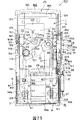
上述のように構成された板状メモリ1が記憶媒体として用いられる記録及び/又は再生装置11は、オーディオデータ等の情報信号を板状メモリ1に記録し、又は板状メモリ1に記録されたオーディオデータ等の情報信号の再生を行うものである。この記録及び/又は再生装置11は、図3及び図4に示すように、合成樹脂を成形した上下一対のハウジング半体12a,12bを突き合わせ結合した装置本体を構成するハウジング12を備えている。
【0024】
ハウジング12内には、図5及び図6に示すように、板状メモリ1を装着し、また、自動的に板状メモリ1を排出するローディング装置が配設されている。このローディング装置は、板状メモリ1が挿入保持されるホルダ13と、このホルダ13が取り付けられるシャーシ14とを備え、ホルダ13がシャーシ14に対して移動可能に取り付けられてなる。
【0025】
ホルダ13が移動可能に配設されるシャーシ14は、図5に示すように、底板15の相対向する両側に一対の第1及び第2の側壁16,17が立ち上がり形成されて、断面コ字状に形成されている。
【0026】
シャーシ14に移動可能に配設されるホルダ13は、図5に示すように、板状メモリ1を支持するメモリ支持板18の相対向する両側に一対の第1及び第2のメモリ保持部19,20が設けられている。ホルダ13の上面側である一対の第1及び第2のメモリ保持部19,20間は開放され、これら第1及び第2のメモリ保持部19,20間に挿入される板状メモリ1の平面2eに設けたラベル貼着部9を外方に臨ませるようにしている。ホルダ13の開放された一端側は、このホルダ13に装脱される板状メモリ1の挿脱口21とされる。ホルダ13の挿脱口21が設けられた一端側に対向する他端側には、このホルダ13に挿入される板状メモリ1に設けた端子部3が電気的に接続されるコネクタ22が取り付けられている。コネクタ22は、図5に示すように、板状メモリ1の端子部3を構成する複数の電極3bにそれぞれ電気的に接続される複数の端子からなる第1の接続端子23が設けられている。第1の接続端子23は、コネクタ22の内方端側に設けられている。また、コネクタ22には、ホルダ13側に突出するようにして、記録及び/又は再生装置11内に設けられる信号処理回路と板状メモリ1内のメモリとの間で板状メモリ1に記録され若しくは板状メモリ1に記録された情報信号の授受を行うための複数の端子からなる第2の接続端子24が設けられている。
【0027】
コネクタ22の上面側には、ホルダ13側に突出して設けられ、コネクタ22の外方に臨む第2の接続端子24を覆う覆板25が設けられている。この覆板25は、ホルダ13がハウジング12内に配設されたとき、後述するようにハウジング12に設けた窓部を介して外方に臨まされる。覆板25の表面には、ホルダ13に挿入される板状メモリ1の挿入方向や、板状メモリ1の装着の有無を示す表示部26が印刷や刻印によって設けられている。
【0028】
上述のように構成されたホルダ13は、シャーシ14の底板15上に載置するようにして、図6中矢印B方向及び反矢印B方向に移動可能に配設される。このとき、ホルダ13は、図示しない移動ガイド軸をシャーシ14側に設けた移動ガイド孔に係合支持することによってシャーシ14からの脱落が防止され、底板15上を、図6中矢印B方向及び反矢印B方向に移動可能に取り付けられる。
【0029】
ホルダ13とシャーシ14との間には、トグルバネ27が取り付けられている。ホルダ13は、板状メモリ1の記録及び/又は再生装置11への挿脱を可能となす初期位置にある状態から板状メモリ1がホルダ13に挿入され、図6中反矢印B方向に移動される。更にホルダ13がシャーシ14の途中位置まで移動されると、トグルバネ27の付勢方向が反転することにより、トグルバネ27の付勢力を受けて図6中反矢印B方向にさらに移動され所定のメモリ装着位置に移動される。
【0030】
また、ホルダ13は、装着位置に移動された状態から、図6中反矢印B方向に移動され、シャーシ14の途中位置まで移動されると、トグルバネ27の付勢方向が反転することにより、トグルバネ27の付勢力を受けて図6中反矢印B方向にさらに移動され板状メモリ1の挿脱を可能とする挿脱位置に移動される。
【0031】
板状メモリ1が挿入され、記録及び/又は再生装置11内のメモリ装着位置に移動されたホルダ13は、シャーシ14の第1の側壁16上に移動可能に支持されたイジェクト部材28が図6中矢印B方向に移動操作されることにより、図6中反矢印B方向に移動され、挿脱位置に移動される。イジェクト部材28は、板状メモリ1をホルダ13に挿入する方向と同方向に移動操作されてホルダ13に挿入保持された板状メモリ1のイジェクト操作を行うものであるので、板状メモリ1のイジェクト操作の操作感を良好にすることができる。
【0032】
なお、イジェクト部材28は、イジェクト部材28とシャーシ14の第1の側壁16との間に張設された引っ張りバネ30の付勢力を受けて図6中反矢印B方向に移動付勢されている。
【0033】
なお、シャーシ14のホルダ13の挿脱口21が臨む一端側には、挿脱口21を開閉する蓋体29が回動可能に取り付けられている。蓋体29は、図示しない付勢部材により常時挿脱口21を閉塞する方向に回動付勢されている。また、蓋体29は、イジェクト部材28の図6中矢印B方向への移動操作に連動して付勢部材の付勢力に抗して挿脱口21を開放する方向に回動操作される。
【0034】
板状メモリ1は、端子部3が設けられた前面2a側を挿入端とし、平面2e側を上方に向けてホルダ13に挿入される。したがって、板状メモリ1は、ホルダ13に挿入されたとき、平面2eに設けたラベル貼着部9が、一対の第1及び第2のメモリ保持部19,20間の開放された部分を介して外方に臨む。
【0035】
上述のようにシャーシ14上に移動可能に取り付けられたホルダ13は、挿脱口21をハウジング12の背面31に設けたメモリ挿脱口32に対向させてハウジング12内に配設される。このとき、ホルダ13は、上面側の一対の第1及び第2のメモリ保持部19,20間の開放された部分をハウジング12の平面33側に位置するようにしてハウジング12内に配設される。
【0036】
ところで、記録及び/又は再生装置11の装置本体を構成するハウジング12の長手方向に亘る中央部より前面35側に位置する一端側には、図3及び図4に示すように、ハウジング12内に配設された液晶表示体等により構成された表示体34の表示面34aを外方に臨ませる第1の窓部36が設けられている。第1の窓部36は、図3及び図4に示すように、ハウジング12の平面33の一端側に位置してハウジング12の両側に亘る矩形状に形成されている。
【0037】
また、ハウジング12の長手方向に亘る中央部より背面31側に位置する他端側の平面33には、図3及び図4に示すように、ハウジング12内に配設されたホルダ13を外方に臨ませる第2の窓部37が設けられている。ホルダ13は、上面側の開放された部分をハウジング12の平面33側に対向させてハウジング12内に配設されることにより、この開放された部分がハウジング12に設けた第2の窓部37を介してハウジング12の外方に臨み、ホルダ13に挿入された板状メモリ1も第2の窓部37を介して外方に臨む。
【0038】
第2の窓部37は、図3及び図4に示すように、ホルダ13の上面側の一対の第1及び第2のメモリ保持部19,20間の開放された部分及びコネクタ22の第2の接続端子24を覆う覆板25をハウジング12の外方に臨ませるように長尺な矩形状に形成されている。このように第2の窓部37が形成されることにより、図7及び図8に示すように、ホルダ13に挿入された板状メモリ1の平面2e側に設けたラベル貼着部9が第2の窓部37を介して外方に臨み、ユーザはラベル貼着部9に貼着されたラベル10に施された表示をハウジング12の外部から目視することができ、板状メモリ1が記録及び/又は再生装置11に装着された状態で、装着された板状メモリ1の種類や、板状メモリ1に記録された情報の内容を確認することができる。同時に、覆板25に施された表示部26も、第2の窓部37を介して外方に臨み、ユーザはハウジング12の外部から表示部26を目視することができる。
【0039】
ところで、覆板25は、ホルダ13とともに移動するコネクタ22に取り付けられているので、板状メモリ1の挿脱に関連してホルダ13とともに第2の窓部37内を移動する。そこで、第2の窓部37に大きさをホルダ13の移動位置に応じて覆板25の第2の窓部37に対向する量が変化するような大きさに形成することにより、覆板25に施される表示部26の第2の窓部37に臨む状態を可変することができる。表示部26により、ホルダ13に板状メモリ1を挿入された状態にあるか、板状メモリ1の挿入を可能とする位置にあるかを容易に識別することができる。すなわち、ホルダ13が、図7に示すように、板状メモリ1の挿脱を可能となすハウジング12の背面31側に設けたメモリ挿脱口32に近接する位置にあるとき、例えば覆板25に設けた挿入方向を示す矢印で構成した表示部26の全体がハウジング12の外方に臨む。ホルダ13が、図8に示すようにこのホルダ13に挿入保持された板状メモリ1を記録及び/又は再生装置11内の装着位置に装着させる位置に移動したとき、表示部26を構成する矢印の矢の部分が覆われような大きさに第2の窓部37が形成されることにより、ユーザによってホルダ13に対する板状メモリ1の挿入状態を容易に確認することができる。
【0040】
第1及び第2の窓部36,37は、ハウジング12の共通の面である平面33に並列して設けられているので、共通の1枚の透視板40によって覆うことができる。透視板40は、光透過性を合成樹脂等によって形成される。透視板40は、第1及び第2の窓部36,37に対応する部分に第1及び第2の透視部41,42が設けられ、他の部分は着色が施されて不透明な部分とされている。また、この透視板40は、少なくとも第1及び第2の透視部41,42にホログラムが設けられ、視野角を制限するようにしている。すなわち、第1及び第2の透視部41,42の視野角を制限することで、第1及び第2の透視部41,42を介して、表示体34に表示される内容や表示部26に記載された内容を第三者に見られることを防止することができる。
【0041】
表示体34の表示面35を外方に臨ませる第1の窓部36及びホルダ13の一部を外方に臨ませる第2の窓部37は、ハウジング12の共通の面である平面33に並列して設けられている。ユーザは、図9に示すように、記録及び/又は再生装置11を片手で把持したとき、第1及び第2の窓部36,37を同時に目視することができるので、板状メモリ1の装着の有無や装着された板状メモリ1の種類等を識別し、表示体34の表示面34aに表示される操作モード等を識別しながら情報信号の記録又は再生を行うことができる。よって、ユーザは、所望の情報を正確に記録又は再生することができるばかりか、操作状態を確実に把握して記録及び/又は再生装置11の操作を行うことができる。
【0042】
本発明に係る記録及び/又は再生装置11は、ハウジング12の一方の側面45側であって、ハウジング12の前面35側に位置するハウジング12の中央部より一端側の位置に、この記録及び/又は再生装置11の操作モードを選択する選択操作部46が設けられている。選択操作部46は、ハウジング12内に設けた回動支点を中心にして、図7中矢印X1方向及び矢印X2方向に回動操作されて記録及び/又は再生装置11の記録モードや再生モード等の操作モードを選択し、ハウジング12の側面45に直交する矢印Y1方向に押圧操作されることにより選択された操作モードを決定する。
【0043】
選択操作部46が設けられたハウジング12の一方の側面45の長手方向の中央部には、選択された操作モードを固定するホールド釦47が設けられている。また、同じ側面45には、操作モードの一覧を表示体34の表示面34aに表示させるためのメニュー釦45が設けられている。
【0044】
ホルダ13は、上面側の一対の第1及び第2のメモリ保持部19,20間の開放された部分を第2の窓部37に対向するようにしてハウジング12内に配設される。第1の側壁16側に設けたイジェクト部材28は、ハウジング12の他方の側面48側に位置する。イジェクト部材28に設けた操作部28aが、ハウジング12の他方の側面48側に突出し、図4に示すように、他方の側面48に沿って図4中矢印B方向及び矢印Bに移動可能に取り付けられたイジェクト操作部50に係合されている。イジェクト操作部50が板状メモリ1を記録及び/又は再生装置11内に挿入する図4中矢印B方向に移動操作されることにより、ホルダ13に挿入保持された板状メモリ1を記録及び/又は再生装置11の外方に突出させるイジェクト操作を行う。このイジェクト操作部50は、図4に示すように、ハウジング12の他方の側面48側に位置し、ハウジング12の中央部より背面31側の他端側に設けられている。
【0045】
上述のように、操作モードを選択する選択操作部46がハウジング12の中央部より一端側に位置する部分に設けられ、イジェクト操作部50がハウジング12の中央部より他端側に位置する部分に設けられるので、ユーザが記録及び/又は再生装置11を図9A、図9B、図9Cに示すように、片手で把持したとき、選択操作部46に親指あるいは人差し指を臨ませると、イジェクト操作部50が手指により操作しにくい位置に置かれ、ユーザがイジェクト操作部50を操作するように親指を位置させると、選択操作部46が手指により操作しにくい置かれるので、ユーザが記録又は再生中に誤ってイジェクト操作部50を操作して記録及び/又は再生装置11に装着された板状メモリ1をイジェクトしてしまうような誤操作を確実に回避することができる。
【0046】
特に、選択操作部46をハウジング12の中央部より一端側に位置する部分に設け、イジェクト操作部50をハウジング12の中央部より他端側に位置する部分に設け、しかも、選択操作部46とイジェクト操作部50をハウジング12の異なる側面45,48に配置することにより、選択操作部46とイジェクト操作部50の誤操作を確実に防止することができる。
【0047】
また、本発明に係る記録及び/又は再生装置11にあっては、図3に示すように、メモリ挿脱口32が設けられるハウジング12の背面31側には、図3及び図4に示すように、パーソナルコンピュータ51やディスクドライブ装置52等の外部機器から供給される制御データやオーディオデータ等のデータや商用電源を直流に変換した駆動電源を供給するための入力部55が着脱可能に取り付けられる。この入力部55は、ハウジング12への突き合わせ面に設けたコネクタ部56をハウジング12の背面31側にメモリ挿脱口32と並列して設けた接続端子部57に接続してハウジング12に取り付けられる。入力部55の一方の側面に外部機器との接続を図るデータ入力用接続端子が接続される第1の接続部58が設けられ、他方の側面に外部電源入力用の電源接続端子が接続される第2の接続部59が設けられている。
【0048】
第1の接続部58は、USB(Universal Serial Bus)に準拠しており、接続コードを介してパーソナルコンピュータ51やディスクドライブ装置52と接続される。そして、板状メモリ1には、記録及び/又は再生装置11に入力部55が取り付けられた状態において、電気通信回線53を介してパーソナルコンピュータ51にダウンロードされたオーディオデータやディスクドライブ装置52で再生される光ディスク等のディスクに記録されているオーディオデータが記録される。ここで、電気通信回線53は、インターネット、公衆電話回線、衛星通信、無線通信を含む。
【0049】
入力部55は、メモリ挿脱口32を覆ってハウジング12の背面31側に取り付けられるので、メモリ挿脱口32を閉塞し、外部機器から板状メモリ1に記録されるデータや制御用のデータが入力されるとき、確実に板状メモリ1の記録及び/又は再生装置11からのイジェクトを規制する。後述するが、メモリ挿脱口32を覆う蓋体29とイジェクト操作部50は連動しているため、入力部55が蓋体29の回動を規制することにより連動されるイジェクト操作部50も規制され、結果的に記憶媒体のイジェクトが規制される。よって、入力部55は、外部機器からデータが入力されているとき、板状メモリ1のイジェクト操作が規制されることから、板状メモリ1に記録されたデータや記録及び/又は再生装置11に供給されたデータの確実な保護を図ることができる。
【0050】
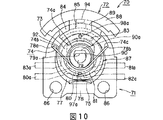
以上のような記録及び/又は再生装置11の操作モードを選択するための選択操作部46は、具体的に図10乃至図15に示すような回動押圧型スイッチ70により構成されている。この回動押圧型スイッチ70は、図13に示すように、上部開口71aを有する合成樹脂製のウエハ71と、このウエハ71に回動可能に保持された操作体72と、この操作体72の下面に固定された導電性弾性板からなる摺動子73と、中央の巻回部74aの両端から一対の腕部74b,74cが突出する捻りコイルバネ74と、ウエハ71内に配置されたクリック板75と、ウエハ71の上部開口71aを覆う蓋部材76とから構成されている。
【0051】
ウエハ71は、図15に示すように、略円形の底部77と、この底部77の周囲に全周にわたって立設された周壁78とからなり、周壁78には、捻りコイルバネ74の一対の腕部74b,74cが係止される一対の係合段部78a,78bが形成されている。底部77の中央には、操作体72を軸支する支軸79が立設されている。支軸79には、操作体72が押圧操作されたときの押圧力を受ける平面部79aが形成されている。また、底部77には、操作体72の回動方向に沿って形成された回動検出用の第1及び第2の固定接点80,81と、操作体72の押圧操作を検出する第3の固定接点82と、支軸79を挟んで第3の固定接点82の反対側に形成され、GNDに接続された共通接点83とが設けられている。これら第1乃至第3の固定接点80〜82は、それぞれ周壁78より突出して形成された第1乃至第3の外部出力端子80a〜82aに電気的に接続されている。また、共通接点83も、周壁78より突出して形成された外部端子83aに電気的に接続されている。
【0052】
周壁78は、支軸79を中心にして略円弧状に形成され、この円弧状部分には、操作体72の回動範囲を規制する規制段部84が形成されている。この規制段部84は、操作体72の回動範囲を規制するもので、中央部分には、操作体72が押圧操作されたとき移動する操作体72のガイドを行うガイド凹部85が形成されている。また、周壁78には、記録及び/又は再生装置11のハウジング12に取り付けるための取付孔86が形成されている。
【0053】
以上のようなウエハ71に配設される操作体72は、左右対称形状に形成され、図13に示すように、ウエハ71内に配置される基部87と、ウエハ71から突出する操作部88と、これら基部87と操作部88を連結する連結部89とからなり、連結部89は、ウエハ71の規制段部84に係合されている。基部87の中央には、円筒状のボス91が立設されており、このボス91に形成された挿通孔90は、操作体72の押圧方向を長手方向として形成され、支軸79が挿通される。また、挿通孔90の周囲には、捻りコイルバネ74を配設するための環状溝87aが形成されており、この環状溝87aには、それぞれ斜め上方向に向かって一対の係合溝92,93が形成されている。
【0054】
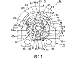
図10に示すように、捻りコイルバネ74の巻回部74aは、ボス91に嵌合されて環状溝87a内に配設され、両腕部74b,74cは、係合溝92,93に係合され、更にウエハ71の係合段部78a,78bに係止される。更に、挿通孔90の平面部79aと対向する位置には、この挿通孔90の長手方向に対して垂直な平面部90aが形成されている。平面部90aは、図10に示すように、非操作時には平面部79aと離間した状態にあり、回動操作されたとき、図11に示すように、平面部79aと位置がずれた状態にあり、押圧操作されたとき、図12に示すように、平面部79aが当接される。
【0055】
操作部88は、基部97を中心として円弧状に形成され、この操作部88の中央の内側には、ガイド凹部85に係合されるガイド突起94が形成されている。図10に示す操作体72の回動操作時に、このガイド突起94は、ガイド凹部85と非係合状態にあり、ウエハ71の規制段部84の外側を移動し、図11に示す操作体72のセンタ位置での押圧操作時に、ガイド突起94は、ウエハ71のガイド凹部85にガイドされて移動する。
【0056】
以上のような操作体72に取り付けられる摺動子73は、導電性の金属板により形成され、基部87の下面に取り付けられる一対の取付部95,96と、これら取付部95,96間に形成された一対の摺接部97,98とを有している。各摺接部97,98には、突出して第1及び第2の可動接点97a,98aが形成され、第2の可動接点98aは、共通接点83と常時接触され、電気的に接続されている。そして、第1の可動接点97aは、操作体72が押圧操作又は回動操作されることで、選択的に第1乃至第3の固定接点80〜82に接触され、電気的に接続される。
【0057】
そして、以上のような操作体72が取り付けられたウエハ71には、上部開口71aを閉塞するように蓋部材76が取り付けられる。この蓋部材76には、この蓋部材76をウエハ71に取り付けるための複数の係止部99が形成されている。蓋部材76は、これら係止部99をウエハ71の周壁78に沿って挿入し、ウエハ71の下面に係止することにより、図14に示すように、ウエハ71の上部開口71aを閉塞する。
【0058】
次に、以上のように構成された回動押圧型スイッチ70の操作方法について説明する。この回動押圧型スイッチ70は、操作体72が押圧操作されたときと、一方に回動操作されたときと、他方に回動操作されたときの3つのモードに切り換えることができる。図10に示すように、非使用時には、操作体72は、捻りコイルバネ74の両腕部74b,74cがウエハ71の係合段部78a,78bにそれぞれ係止され、巻回部74aが操作体72のボス91に巻回されているため、捻りコイルバネ74によりセンタ位置への付勢力が付与されている。このとき、操作体72のガイド突起94は、ウエハ71のガイド凹部85と非係合状態にあり、また、操作体72の挿通孔90の平面部90aと支軸79の平面部79aとが離間した状態にある。また、摺動子73の第2の可動接点98aは、共通接点83に常時接触しているが、第1の可動接点97aは、第1乃至第3の固定接点80〜82の何れにも接触していない状態にある。したがって、回動押圧型スイッチ70は、何れの電気信号も出力していないオフの状態にある。
【0059】
何れの電気信号も出力していない状態を基本状態とし、この基本状態から操作体72が反時計方向に回動されると、図11に示すように、操作体72に連動して摺動子73も支軸79を中心にして回動し、摺動子73の第1の可動接点97aが回動検出用の第2の固定接点81に接触する。これにより、回動押圧型スイッチ70は、第2の外部端子81aより第1の電気信号を出力する。
【0060】
なお、捻りコイルバネ74の一方の腕部74bは、ウエハ71の係合段部78aに係止され、他の腕部74cは、操作体72の係合溝93の端部により回動方向に押圧されて係合段部78bから離れた状態にある。すなわち、捻りコイルバネ74は、腕部74b,74cが閉じる方向に圧縮されることにより、操作体2にセンタ位置への復帰力を付与している。ユーザが操作部88を手放すと、操作体72は、捻りコイルバネ74の付勢力で時計方向に回動し、図10に示すセンタ位置まで自動的に戻る。回動押圧型スイッチ70は、第1の可動接点97aが回動検出用の第2の固定接点81から離れ、電気的に切断されることで、図10に示す状態に戻り、オフの状態となる。なお、操作体72の回動操作中に、ガイド突起94は、ガイド凹部85から離れて、規制段部84の外側を移動する。回動押圧型スイッチ70は、操作体72の回動操作時に誤って操作体72に押圧力が加わった場合にも、ガイド突起94が規制段部84に当接することで、ユーザは操作体72を押圧操作することができなくなり、誤操作を防止することができる。
【0061】
同様に、操作体72が時計方向に回動操作された場合、摺動子73の第2の可動接点98aは、共通接点83に常時接触しており、第1の可動接点97aは、回動検出用の第1の固定接点80に接触し、共通接点83aと導通する。これにより、回動押圧型スイッチ70は、オン状態となり、第1の外部端子80aを第2の電気信号を出力する。
【0062】
図10に示す操作体2が押圧操作される場合、操作部18をウエハ1の方向へ押圧すると、図12示すように、操作体72及び摺動子73は、挿通孔90の押圧方向へ移動する。これに伴って、クリック板75が基部87に押圧されて座屈変形するため、クリック感が生起される。これと共に、摺動子73の第1の可動接点97aは、第3の固定接点82に接触する。これにより、回動押圧型スイッチ70は、オンの状態となり、第3の外部端子82aを介して、第3の電気信号を出力する。
【0063】
このとき、捻りコイルバネ74は、両腕部74b,74cがウエハ71の係合段部78a,78bに係止されているが、巻回部74aが操作体72のボス91によって押圧方向に移動するため、これら腕部74b,74cが閉じる方向に圧縮され、操作体72をセンタ位置へ付勢する。ユーザが操作部88を手放すと、操作体72は、捻りコイルバネ74の付勢力で上昇して図10に示すセンタ位置まで自動的に戻る。これにより、第1の可動接点97aは、押圧検出用の固定接点82から離れ、回動押圧型スイッチ70は、再びオフ状態となる。回動押圧型スイッチ70は、操作体72の押圧操作中に、ガイド突起94がガイド凹部85にガイドされて移動するため、操作体72の押圧操作時に誤って回動方向の力が作用しても、ガイド突起94がガイド凹部85の壁面に当接して操作体2の回動を禁止することから誤操作を防止することができる。
【0064】
記録及び/又は再生装置11の操作モードを選択するための選択操作部46は、以上のような回動押圧型スイッチ70により構成され、図7に示すように、操作体72が図7中矢印X1方向又は矢印X2方向に回動され、また、図7中矢印Y1方向に押圧されることで、記録及び/又は再生装置11の操作モードが選択され決定される。
【0065】
ここで、具体的に、回動押圧型スイッチ70により構成される選択操作部46の使用方法について説明する。例えば、ユーザが板状メモリ1に記憶されたオーディオデータを再生する場合について説明する。図8に示すように、記録及び/又は再生装置11は、オーディオデータの再生をしているとき、選択操作部46が図8中矢印Y1方向に一度押圧されると、再生動作を一時停止し、図8中矢印X1方向に一度回動されると、再生中の曲の頭出しを行い、断続して図8中矢印X1方向に回動されると、回動された回転角度分、前に記録された曲の頭出しを行う。記録及び/又は再生装置11は、オーディオデータを再生しているとき、選択操作部46が図8中矢印X2方向に回動されると、現在再生中の曲の次に記録された曲の頭出しを行い、断続して図8中矢印X2方向に回動されると、回動された角度分後に記録された曲の頭出しを行う。更に、記録及び/又は再生装置11は、オーディオデータを再生しているとき、選択操作部46が図8中矢印X1方向に回動され続けると、再生中のオーディオデータを巻き戻し、図8中矢印X2方向に回動され続けると、再生中のオーディオデータを早送りする。
【0066】
更にまた、記録及び/又は再生装置11は、図4に示すメニュー釦44が押されたとき、表示体34の表示面34aには記録及び/又は再生装置11の操作メニューが表示される。具体的に、メニュー釦44が押されたとき、表示体34の表示面34aには、再生されるオーディオデータの低音を強調するように音質を変更する音質変更機能、板状メモリ1に記録されたオーディオデータを繰り返し再生するためのリピート機能、イヤホン等でオーディオを聴いているときに再生音がイヤホンより漏れ周囲の人に迷惑をかけることを防止するため、音量を制限する音量制限機能等の記録及び/又は再生装置11の機能の一覧が表示される。ユーザは、上述した選択操作部46を図8中矢印X1方向又は矢印X2方向に回動することで、表示面34aに表示された操作メニューの中から1つを選択する。次いで、ユーザが、選択操作部46を図8中矢印Y1方向に押圧操作することで、選択された記録及び/又は再生装置11の動作が決定される。ユーザは、更に選択操作部46を図8中矢印X1方向又は矢印X2方向に回動することで、例えば選択した動作のオン、オフを選択し、次いで、図8中矢印Y1方向に押圧することで、オン、オフを設定することができる。
【0067】
例えば、ユーザがメニュー釦44を押圧し、表示面34aに表示された操作メニューの中から、選択操作部46を図8中矢印X1方向又は矢印X2方向に回動することで、音質変更機能を選択し、図8中矢印Y1方向に押圧操作すると、表示面34aには、音質表示機能のオンとオフの表示がされる。ユーザは、更に選択操作部46を図8中矢印X1方向又は矢印X2方向に回動し、音質表示機能のオンオフを選択し、図8中矢印Y1方向に押圧することで、音質変更機能のオン、オフを切り換えることができる。
【0068】
以上のように回動押圧型スイッチ70により構成される選択操作部46は、3方向に操作することができることから、少ない操作釦で多くの機能の切り換えを行うことできる。特に、手のひらサイズにまで小型化された記録及び/又は再生装置11のような電子機器の場合には、操作釦を設けるスペースも少ないことから、回動押圧型スイッチ70により構成される選択操作部46を設けることは有効である。
【0069】
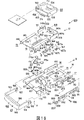
ところで、記録及び/又は再生装置11に用いられる板状メモリ1のハウジング12内に配設されるローディング装置は、具体的には、次のように構成されている。このローディング装置120は、図16及び図17に示すように、ハウジング12に取り付けられるシャーシ14と、このシャーシ14にスライド可能に取り付けられるとともに、板状メモリ1を保持するホルダ13とを備える。
【0070】
シャーシ14は、図16及び図17に示すように、金属板を打ち抜き折曲して形成され、略矩形状の底板15と、この底板15の長手方向の両側に互いに略平行となるように立ち上がり形成された第1及び第2の側壁16,17とを備え、全体が断面略コ字状となるように形成されている。そして、ホルダ13は、底板15と第1及び第2の側壁16,17とに囲まれる領域に、板状メモリ1の挿入方向と同じ図16及び図17中矢印B及び反矢印B方向に移動可能に配設される。
【0071】
ホルダ13が配設される底板15は、長手方向の長さが板状メモリ1の長手方向の長さとほぼ同じ略矩形状に形成され、背面側にホルダ13の移動をガイドするためのガイド孔129,129がホルダ13の移動方向に沿って形成されている。これらガイド孔129,129は、ホルダ13の底面に突出したガイド突起が係合され、ホルダ13の移動領域を規制している。第1及び第2の側壁16,17には、ホルダ13の移動をガイドし、移動領域を規制するガイド孔130,130がホルダ13の移動方向に沿って形成されている。
【0072】
底板15の板状メモリ1の挿入側となる前面側には、図16及び図17中矢印B方向にスライドしたホルダ13を同図中反矢印B方向にスライドさせる回動アーム131が取り付けられている。この回動アーム131は、中程が、底板15に設けられた支軸132に軸支され、この支軸132を中心に図16及び図17中矢印C方向又は反矢印C方向に回動可能に支持されている。この回動アーム131は、第1及び第2の側壁16,17間の間隔とほぼ同じ長さを有し、第1の側壁16側の一端部に、ホルダ13を図16及び図17中反矢印B方向に押圧する押圧部133が形成され、第2の側壁17側の他端部に、イジェクト部材28の押圧部により押圧される被押圧部134が形成されてなる。回動アーム131の一端部に形成された押圧部133は、底板15に形成された開口部135より外方に臨まされている。また、他端部に形成された被押圧部134は、イジェクト部材28との接続を図るため、シャーシ14の底板15と第2の側壁17とに亘って形成された開口部136より外方に臨まされている。
【0073】
回動アーム131は、イジェクト部材28の操作子28aにより被押圧部134が図16及び図17中矢印C方向に押圧されることで、支軸132を中心に同図中矢印C方向に回動し、他端側の押圧部133をシャーシ14の前面側に移動させる。これにより、シャーシ14の背面側に位置しているホルダ13は、シャーシ14の前面側に移動する押圧部133に押圧されて、シャーシ14の前面側、すなわち図16及び図17中反矢印B方向にスライドされる。
【0074】
なお、底板15には、記録及び/又は再生装置11のハウジング12に取り付けるための複数の取付孔137が形成されている。
【0075】
以上のようなシャーシ14にスライド可能に取り付けられるホルダ13は、図16及び図17に示すように、シャーシ14よりやや小さい大きさで、金属板を折曲して形成されている。このホルダ13は、メモリ支持板18の前面側両側に板状メモリ1を保持する第1及び第2のメモリ保持部19,20が形成されている。これら第1及び第2のメモリ保持部19,20は、メモリ支持板18の両側を垂直に折り曲げて形成され、板状メモリ1と厚さ分の高さを有する互いに略平行な側壁144,145と、これら側壁144,145の先端側をメモリ支持板18と平行となるように折り曲げて形成された支持片146,147とから構成されている。ホルダ13の前面側には、第1及び第2のメモリ保持部19,20とメモリ支持板18とで構成される板状メモリ1を挿脱するための挿脱口21が形成されている。また、第1のメモリ保持部19と第2のメモリ保持部20との間は、開放されており、第1及び第2のメモリ保持部19,20が板状メモリ1を保持したとき、ユーザはラベル貼着部9に貼着されたラベル10をハウジング12の第2の窓部37を介して目視することができる。
【0076】
また、ホルダ13の背面側には、板状メモリ1の挿入端に設けられた電極3bが接続されるコネクタが取り付けられるコネクタ取付部148が形成されている。このコネクタ取付部148は、メモリ支持板18の前面側を除く側縁に形成されたコネクタの取付位置を規制する規制壁149a,149b,149cとメモリ支持板18とにより構成されている。規制壁149a,149b,149cの先端には、コネクタ取付部148にコネクタを係止するためのコネクタ係止片151が形成されている。コネクタ取付部148を構成するメモリ支持板18には、コネクタを位置決めして取り付けるための位置決め孔150,150が形成されている。
【0077】
コネクタ取付部148に取り付けられるコネクタ22は、図16及び図17に示すように、板状メモリ1の電極3bとの接続を図るための端子板153と、この端子板153に取り付けられる断面略コ字状のカバー154とから構成される。コネクタ22は、端子板153にカバー154が取り付けられることで、内部に板状メモリ1の前面側が収納される収納部が形成され、前面側に端子部3が形成された板状メモリ1の前面が挿入される挿入口155が形成されている。
【0078】
カバー154には、一方の側壁に、板状メモリ1が挿入された際、板状メモリ1の脱落防止用凹部7に係合される脱落防止片を構成する弾性係合片160が設けられている。弾性係合片160は、板状メモリ1の脱落防止用凹部7に係合されることで、板状メモリ1をホルダ13内に保持し、ローディング装置120に装着された板状メモリ1が脱落しないようにする。弾性係合片160は、板状メモリ1の脱落防止用凹部7に係合するとき、弾性変位することで、利用者にクリック感を与え、利用者に板状メモリ1がホルダ13に完全に挿入されたことを認識させる。この弾性係合片160は、板状メモリ1が正規な状態で挿入されなかったとき、板状メモリ1がホルダ13内に挿入されることを阻止する誤挿入防止片としても機能する。なお、コネクタ22には、カバー154の背面壁に板状メモリ1の背面に設けた切り欠き部4及び誤挿入防止溝5に係合する脱落防止部材を設けてもよい。
【0079】
コネクタ22の底面を構成する端子板153には、板状メモリ1の端子部3が電気的に接続される第1の接続端子23と、信号処理回路等の電気回路が組み込まれたプリント配線基板と電気的に接続するためフレキシブルプリント配線基板が接続される第2の接続端子24とが設けられている。第1の接続端子23は、板状メモリ1の端子部3を構成する電極3bの数に対応して設けられている。これら第1の接続端子23は、略L字状に折曲され、この折曲部が上方に突出し、板状メモリ1の電極3bに押圧されて弾性変位する。第1の接続端子23は、板状メモリ1が挿入されたとき、板状メモリ1の端子部3の開放側より進入し、電極3bに押圧状態で接触することで、電極3bと電気的に接続される。
【0080】
第2の接続端子24には、信号処理回路等の電気回路が組み込まれたプリント配線基板と電気的に接続するためのフレキシブルプリント配線基板が接続される。すなわち、第1の接続端子23に端子部3が電気的に接続された板状メモリ1は、第2の接続端子24とハウジング12に配設されるプリント配線基板とを電気的に接続するフレキシブルプリント配線基板を介して、プリント配線基板に設けられた信号処理回路により制御される。第2の接続端子24は、フレキシブルプリント配線基板との接続を容易にするため挿入口155の近傍に設けられている。フレキシブル配線基板は、ホルダ13がシャーシ14の前面側の挿脱位置と背面側の装着位置とに亘って移動し得る長さに形成されている。上述のような第1の接続端子23と第2の接続端子24が設けられたコネクタ22を構成する端子板153の裏面側には、ホルダ13のメモリ支持板18に構成されたコネクタ取付部148に位置決めして取り付けるための位置決め突起158,158が設けられている。
【0081】
コネクタ22を構成するカバー154の天板には、上述した覆板25が接着等により取り付けられる。覆板25は、端子板153に設けられた第2の接続端子24を覆うようにカバー154の天板に取り付けられている。この覆板25は、ローディング装置120がハウジング12に取り付けられたとき、ハウジング12の第2の窓部37を介して外方に臨まされる。すなわち、覆板25は、第2の接続端子24を隠すことができる程度で、且つ第1及び第2のメモリ保持部19,20に板状メモリ1が挿入されたとき、ラベル貼着部9に貼着されたラベル10を隠さない程度の大きさに形成される。この覆板25の表面には、ホルダ13に挿入される板状メモリ1の挿入方向や、板状メモリ1の装着の有無を示す表示部26が印刷や刻印によって設けられている。
【0082】
端子板153にカバー154が取り付けられたコネクタ22は、メモリ支持板18のコネクタ取付部148に形成された位置決め孔150,150に端子板153の位置決め突起158,158が係合され、コネクタ取付部148を構成する規制壁149a,149b,149cの先端部に形成されたコネクタ係止片151が折曲されコネクタ22が係止されることで、コネクタ取付部148に取り付けられる。なお、端子板153に形成された位置決め突起158,158は、メモリ支持板18の位置決め孔150,150を挿通し、ホルダ13のメモリ支持板18より突出し、この突出した部分がシャーシ14に形成されたガイド孔129,129に係合することで、ホルダ13がシャーシ14に対して移動する際のガイド突起としても機能する。
【0083】
ホルダ13の側壁144,145と平行なコネクタ取付部148を構成する規制板149a,149bには、図16に示すように、外側の面にシャーシ14の第1及び第2の側壁16,17に形成されたガイド孔130,130に係合されるガイド突起159,159が設けられている。また、ホルダ13のメモリ支持板18には、ホルダ13の移動方向に沿って、ガイド孔171が形成されている。このガイド孔171には、シャーシ14の底板15に取り付けられた回動アーム131の支軸132が係合される。すなわち、この支軸132も、ホルダ13がシャーシ14に対して移動する際のガイド突起としても機能する。
【0084】
ホルダ13の第2のメモリ保持部20を構成する側壁145には、図16、図17及び図18に示すように、シャーシ14に対するホルダ13の移動を規制する規制部材161が回動可能に取り付けられている。規制部材161は、基端側に、軸孔162が形成され、ホルダ13の側壁145に設けられ支軸162aに挿通されることにより図18中矢印D及び反矢印D方向に回動可能に支持される。
【0085】
規制部材161は、先端側に、板状メモリ1がホルダ13に挿入された際、板状メモリ1の係合凹部8に係合される係合突部163が形成されている。係合突部163は、ホルダ13に保持された板状メモリ1の係合凹部8に係合されるように、ホルダ13のメモリ支持板18及び側壁145に亘って形成された開口部164よりホルダ13内に臨まされる。また、規制部材161の係合突部163の更に先端側には、メモリ支持板18及び側壁145に形成された開口部164の周縁の裏面側に係止され、規制部材161の図18中矢印D方向の回動領域を規制する係止部165が形成されている。この係止部165の近傍には、ホルダ13がシャーシ14にスライド可能な状態で取り付けられたとき、シャーシ14の底板15の開口部136の近傍に設けられた係合突起170に係合される規制孔166が形成されている。規制孔166は、シャーシ14に形成された係合突起170に係合することで、ホルダ13がシャーシ14の前面側の挿脱位置よりシャーシ14の背面側の装着位置にスライドすることを禁止する。すなわち、挿脱位置にあるホルダ13に板状メモリ1が挿入されるとき、ホルダ13が規制部材161により挿脱位置にロックされていることから、板状メモリ1の端子部3が第1の接続端子23に確実に接続される。
【0086】
上述のような規制部材161は、付勢部材であるトーションバネ167によりホルダ13の内方側である図18中矢印D方向に付勢されている。トーションバネ167は、基体部167aがホルダ13の側壁145に植立された支軸162aに規制部材161の上側から嵌合される。更にトーションバネ167の一方のアーム部167bがホルダ13の側壁145に形成された係止片168に係止され、他方のアーム部167cが規制部材161に形成された係止片169に係止される。上述の構成によりトーションバネ167は、規制部材161を図18中矢印D方向に付勢している。規制部材161は、先端部の係止部165を開口部164の近傍のメモリ支持板18の裏面側に係止させ、係合突部163を開口部164よりホルダ13内に臨ませた状態で側壁145に取り付けられている。
【0087】
上述のように構成されるホルダ13は、図16及び図17に示すように、コネクタ取付部148を構成する規制板149a,149bに設けられたガイド突起159,159がシャーシ14のガイド孔130,130に係合し、コネクタ取付部148に取り付けられた端子板153の位置決め突起158,158がシャーシ14のガイド孔129,129に係合する。更に、ホルダ13は、シャーシ14側の回動アーム131の支軸132がホルダ13のメモリ支持板18に形成されたガイド孔171に係合されることにより、シャーシ14の第1及び第2の側壁16,17間にスライド可能に取り付けられる。ホルダ13は、板状メモリ1の挿脱が行われるシャーシ14の前面側の挿脱位置と、板状メモリ1内の半導体メモリに対して情報信号の書き込み又は読み出しを行うシャーシ14の背面側の装着位置とに亘ってスライドされる。ここで、挿脱位置とは、上述した図7に示す状態であり、装着位置とは、上述した図8に示す状態である。ホルダ13が挿脱位置にあるとき、板状メモリ1の挿脱が行われ、ホルダ13が装着位置にあるときに、板状メモリ1内の半導体メモリに対して情報信号の書き込み又は読み出しが行われる。
【0088】
シャーシ14とホルダ13とは、図16及び図17に示すように、付勢部材であるトグルバネ27により接続される。このトグルバネ27は、線状部材が巻回されてなるコイル部174と、コイル部174より一方の側に延びた第1のアーム部175と、コイル部174より他方の側に延びた第2のアーム部176とからなる。そして、第1のアーム部175の先端部には、シャーシ14側に係合される第1の係合部175aが形成され、第2のアーム部176の先端部には、ホルダ13側に係合される第2の係合部176aが形成されている。第1の係合部175aは、シャーシ14を構成する底板15の裏面側に設けられた第1の係合突起177に係合され、第2の係合部176aは、ホルダ13を構成するメモリ支持板18の裏面側に設けられた第2の係合突起178に係合される。
【0089】
上述のようにシャーシ14とホルダ13を接続したトグルバネ27は、ホルダ13がシャーシ14の前面側に移動した挿脱位置にあるとき、図16及び図17中反矢印B方向に付勢する第1の状態にある。ホルダ13がシャーシ14に対して図16及び図17中矢印B方向にスライド操作されると、トグルバネ27は、ホルダ13を図16及び図17中矢印B方向に付勢する第2の状態に反転し、ホルダ13をシャーシ14の背面側の装着位置にスライドさせる。また、ホルダ13が装着位置にあるとき、シャーシ14の底板15に取り付けられた回動アーム131が図17中矢印C方向に回動されると、回動アーム131の一端に形成された押圧部133は、ホルダ13の第2の係合突起178を押圧する。第2の状態にあるトグルバネ27は、回動アーム131の押圧部133がホルダ13の第2の係合突起178を押圧する押圧力を受けて、ホルダ13が図17中反矢印B方向にスライドされることにより、図17中反矢印B方向にホルダ13を付勢する第1の状態に反転し、ホルダ13を挿脱位置に移動させる。
【0090】
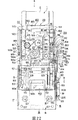
上述のようにホルダ13がスライド可能に取り付けられたシャーシ14には、ホルダ13の前面側に形成された板状メモリ1の挿脱口21とシャーシ14の前面を開閉する蓋体29が回動可能に取り付けられている。蓋体29は、図16、図17、図19及び図20に示すように、挿脱口21及びシャーシ14の前面を閉塞する閉塞板182と、この閉塞板182の両側に形成される第1及び第2の回動支持アーム183,184とを備える。
【0091】
閉塞板182は、ホルダ13の挿脱口21及びシャーシ14の前面を閉塞する第1の閉塞部185と、シャーシ14の底板15の前面に形成された切欠部180に嵌合する第2の閉塞部186とからなる。
【0092】
シャーシ14の第1の側壁16側に位置する第1の回動支持アーム183は、図19に示すように、先端側に、蓋体29を回動支持するための第1の支持孔187が形成されている。この第1の支持孔187は、シャーシ14の第1の側壁16の前面側に設けられた第1の支軸188に係合される。蓋体29は、第1の回動支持アーム183側で、付勢部材であるトーションバネ189により挿脱口21を閉塞する図20中矢印E方向に回動付勢されている。トーションバネ189は、基体部189aがシャーシ14の第1の側壁16に形成された係合片191に係合される。更に、トーションバネ189は、一方のアーム部189bが第1の移動支持アーム183の先端部に形成された係止部192に係止され、他方のアーム部189cが第1の側壁16に形成された係止部193に係止されることで、蓋体29を図20中矢印E方向に回動付勢している。
【0093】
シャーシ14の第2の側壁17側に位置する第2の回動支持アーム184は、図20に示すように、先端側に第1の支持孔187とともに蓋体29を回動支持するための第2の支持孔194が形成されている。この第2の支持孔194は、シャーシ14の第2の側壁17の前面側に設けられた第2の支軸195に係合される。第2の回動支持アーム184の先端部には、イジェクト部材28により押圧されて蓋体29を図20中反矢印E方向に回動するための突部196が設けられる。突部196の下側には、閉塞板182側にイジェクト部材28のカム部が接触しやすくするため傾斜面部197が形成されている。
【0094】
上述のような蓋体29は、図19及び図20に示すように、第1及び第2の支持孔187,194に第1及び第2の支軸188,195が係合されることで、第1及び第2の支軸188,195を中心に図19及び図20中矢印E方向及び反矢印E方向に回動可能に支持されている。蓋体29は、トーションバネ189の付勢力により、シャーシ14の前面を閉塞する図19及び図20中矢印E方向に回動付勢されている。第2の回動支持アーム184に形成された突部196の傾斜面部197がイジェクト部材28のカム部により押圧されることで、蓋体29は、図19及び図20中反矢印E方向に第1及び第2の支軸188,195を中心に回動され、シャーシ14の前面及びホルダ13の挿脱口21を開放する。
【0095】
シャーシ14の第2の側壁17には、図16及び図17に示すように、シャーシ14とホルダ13とを連結するトグルバネ27によりシャーシ14の背面側である装着位置にあるホルダ13を、シャーシ14の前面側の挿脱位置に移動させるイジェクト部材28が設けられる。イジェクト部材28は、第2の側壁17に長手方向、すなわち図20中矢印B方向及び反矢印B方向にスライド可能に取り付けられている。イジェクト部材28は、図20に示すように、シャーシ14の第2の側壁17の高さとほぼ同じ幅を有し、長尺の略矩形状に金属板を打ち抜いて形成されている。イジェクト部材28には、長手方向に沿って、第1のガイド孔202と第2のガイド孔203とが形成されている。第1のガイド孔202には、シャーシ14の第2の側壁17に設けられたガイド突部204が係合され、第2のガイド孔203には、第2の側壁17に形成されたガイド片205が係合される。イジェクト部材28は、第1のガイド孔202に第2の側壁17に形成されたガイド突部204に形成されたねじ孔206aに、止めねじ206が螺合されることにより第2の側壁17に取り付けられる。
【0096】
イジェクト部材28は、図20に示すように、付勢部材である引っ張りバネ30により図20中反矢印B方向に付勢されている。この引っ張りバネ30は、一端がイジェクト部材28のシャーシ14の背面側に対応する端部に形成されたバネ係止片211に係止され、他端がシャーシ14の第2の側壁17の長手方向の中程に形成されたバネ係止片212に係止されることで、イジェクト部材28を図20中反矢印B方向に付勢している。
【0097】
上述のようにシャーシ14の第2の側壁17に取り付けられるイジェクト部材28には、図20に示すように、シャーシ14の前面側に位置する一端側に、シャーシ14の底板15と平行となるように折曲して、上述した蓋体29の第2の回動支持アーム184に形成された突部196を押圧するカム部207が形成されている。カム部207は、シャーシ14の底板15に形成された開口部136よりシャーシ14内に臨まされている。そして、カム部207は、蓋体29の第2の回動支持アーム184に設けられた突部196の下側に形成された傾斜面部197を押圧しやすくするため、シャーシ14の背面側となる側に下側に折曲した折曲部208が形成されている。
【0098】
イジェクト部材28のシャーシ14の前面側に位置する一端側には、上述した回動アーム131の他端側に形成された被押圧部134をシャーシ14の背面側、すなわち図20中矢印C方向に押圧する操作片209がシャーシ14の底板15と平行となるように折曲して形成されている。操作片209には、イジェクト部材28の先端側に上側に折曲して押圧部210が形成されている。操作片209に形成された押圧部210は、シャーシ14の底板15に形成された開口部136よりシャーシ14内に臨まされ、回動アーム131の被押圧部134に係合される。
【0099】
更に、イジェクト部材28の一端側には、図示しないが装置本体を構成する筐体より外方に臨まされたイジェクト操作部50によりスライド操作される操作子28aが折り曲げ形成されている。イジェクト部材28は、操作子28aが図20中矢印B方向にスライド操作されることで、同方向にスライドされる。
【0100】
上述のようなイジェクト部材28は、ホルダ13がシャーシ14の背面側の装着位置にある状態において、図20に示すように、図20中矢印B方向に押圧され、イジェクト部材28を図20中反矢印B方向に付勢する引っ張りバネ30の付勢力に抗して図20中矢印B方向にスライドされる。イジェクト部材28が図20中矢印B方向にスライドされると、カム部207は、蓋体29の第2の回動支持アーム184に設けられた突部196の下側に形成された傾斜面部197を押圧し、蓋体29をトーションバネ189の付勢力に抗してホルダ13の挿脱口21を開放する図20中反矢印E方向に回動させる。これと同時に、操作片209に形成された押圧部210は、回動アーム131の被押圧部134を図20中矢印C方向に押圧し、同方向に回動アーム131を回動させる。回動アーム131の一端に形成された押圧部133は、ホルダ13の第2の係合突起178を押圧し、ホルダ13を図17中反矢印B方向にスライドさせる。回動アーム131の押圧部133がホルダ13の第2の係合突起178を押圧する押圧力を受けて、ホルダ13が図17中反矢印B方向にスライドされる。ホルダ13が図17中反矢印B方向にスライドされると、トグルバネ27は、ホルダ13を図17中反矢印B方向に付勢する第1の状態に反転し、ホルダ13を挿脱位置に付勢し、ホルダ13を挿脱位置に移動させる。
【0101】
上述のように構成されたローディング装置120に板状メモリ1が挿入されてから板状メモリ1内の半導体メモリに対する情報信号の記録又は再生が行われるまでの一連の動作について説明する。先ず、非使用時のローディング装置120について説明すると、図17に示すように、ホルダ13は、シャーシ14の前面側に移動した挿脱位置にあり、シャーシ14とホルダ13を接続するトグルバネ27は、ホルダ13をシャーシ14の前面側の挿脱位置に付勢する第1の状態にある。
【0102】
蓋体29は、蓋体29側の係止部192とシャーシ14側の係止部193に係止されたトーションバネ189の付勢力により、シャーシ14の前面を閉塞する図19及び図20中矢印E方向に回動付勢され、シャーシ14の前面及び挿脱位置にあるホルダ13の挿脱口21を閉塞する。蓋体29は、ホルダ13の挿脱口21からローディング装置120内に塵埃等が侵入することを防止している。
【0103】
回動アーム131は、押圧部133がシャーシ14の前面側に位置するように、図17中矢印C方向に回動されている。また、シャーシ14の第1の側壁16に取り付けられた規制部材161は、図18に示すように、一方のアーム部167bが側壁145に形成された係止片168に係止され、他方のアーム部167cが回動アーム131に形成された係止片169に係止されたトーションバネ167により図18中矢印D方向に回動付勢される。規制部材16は、先端部の係止部165がホルダ13のメモリ支持板18に形成された開口部164の近傍の裏面に係止された状態にあり、先端側に設けられた係合突部163がホルダ13内に臨み、規制孔166がシャーシ14の底板に設けられた係合突起170と係合していない状態にある。すなわち、ホルダ13は、規制部材161の規制孔166がシャーシ14の係合突起170に係合されていないことにより、シャーシ14に対し、背面側となる図17中矢印B方向に移動可能な状態にある。
【0104】
イジェクト部材28は、イジェクト部材28側のバネ係止片211とシャーシ14側のバネ係止片212とに係止された引っ張りバネ30により、シャーシ14の前面側となる図17及び図20中反矢印B方向にスライドされた状態にある。
【0105】
この状態は、上述した図7に示す状態であり、ユーザは、ハウジング12に設けられた第2の窓部37を介して覆板25に設けられた表示部26を目視することができ、ユーザは、板状メモリ1の記録及び/又は再生装置11への挿入方向を容易に識別することができる。
【0106】
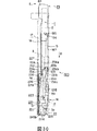
上述のような非使用時のローディング装置120には、図21に示すように、板状メモリ1が端子部3が設けられた前面側を挿入端とし、主面2aをシャーシ14の底板15と対向する下側にして挿入される。板状メモリ1がローディング装置120の前面側より挿入されるとき、蓋体29は、手指又は板状メモリ1の前面部を引っかける等して、蓋体29をシャーシ14の前面を閉塞する図19及び図20中矢印E方向に付勢するトーションバネ189の付勢力に抗して、シャーシ14の前面側、すなわちシャーシ14の前面側の挿脱位置にあるホルダ13の挿脱口21を開放する同図中反矢印E方向に回動される。
【0107】
シャーシ14の前面を蓋体29が開放すると同時に、図21に示すように、ホルダ13の挿脱口21からは、板状メモリ1が端子部3を挿入端として挿入される。図16及び図21に示すように、板状メモリ1の前面側の先端と主面2a側に形成された係合凹部8との間の領域がホルダ13内に臨まされた規制部材161上を図21中矢印B方向に移動しているとき、規制部材161は、ホルダ13内に臨まされた規制部材161の係合突部163が板状メモリ1の先端と主面2a側に形成された係合凹部8との間の領域により押圧されることで、トーションバネ167の付勢力に抗して、支軸162aを回動支点として、図21中反矢印D方向に回動される。規制部材161が反矢印D方向に回動されることにより、規制部材161の規制孔166は、図18及び図21に示すように、シャーシ14側の係合突起170と係合され、シャーシ14の前面側の挿脱位置にあるホルダ13は、板状メモリ1の挿入に伴ってシャーシ14の背面側の図21中矢印B方向にスライドすることを禁止された状態となる。ホルダ13は、板状メモリ1の端子部3がホルダ13に設けられたコネクタ22の第1の接続端子23に接続されるまで規制部材161により挿脱位置にロックされることで、確実に端子部3を構成する電極3bがコネクタ22の第1の接続端子23に接続される。
【0108】
更に、板状メモリ1がローディング装置120内に挿入されると、図22及び図23に示す状態となる。すなわち、ホルダ13がシャーシ14の前面側の挿脱位置にあるとき、板状メモリ1が挿脱位置にあるホルダ13に完全に挿入されると、板状メモリ1は、ホルダ13の背面側に配設されたコネクタ22の挿入口155より挿入される。コネクタ22の第1の接続端子23は、板状メモリ1の端子部3の開放端より係合凹部3cに係合し、電極3bを押圧した状態で電極3bと電気的な接続が図られる。
【0109】
板状メモリ1の係合凹部3cに第1の接続端子23が係合し、電極3bと第1の接続端子23とが接続されたとき、板状メモリ1の係合凹部8は、ホルダ13内の規制部材161の係合突部163の上方に位置する。すると、これまで板状メモリ1の先端から係合凹部8に亘る領域に係合突部163が押圧され、図23中反矢印D方向に回動されていた規制部材161は、板状メモリ1の係合凹部8と規制部材161の係合突部163が係合可能な状態となることで、トーションバネ167の付勢力により図23中矢印D方向に回動され、係合突部163が板状メモリ1の係合凹部8に係合される。これにより、これまでシャーシ14の係合突起170に係合されていた規制部材161の規制孔166と係合突起170との係合状態は解除され、ホルダ13は、シャーシ14の背面側である装着位置の方向である図22及び図23中矢印B方向にスライド可能な状態になる。板状メモリ1がホルダ13に完全に挿入されたとき、図17に示すように、コネクタ22に設けられた弾性係合片160は、板状メモリ1の脱落防止用凹部7に係合し、板状メモリ1がホルダから抜け落ちることを防止している。弾性係合片160は、板状メモリ1の脱落防止用凹部7に係合したとき、弾性変位することで利用者にクリック感を与え、板状メモリ1がホルダ13内に完全に挿入されたこと、すなわち、、端子部3と第1の接続端子23とが確実に係合していることをユーザに認識させる。この状態は、上述した図7に示す状態であり、ユーザが第2の窓部37を介して覆板25に設けられた表示部26を目視することができる状態である。
【0110】
ここで、板状メモリ1が上述のような正規な状態でローディング装置120に挿入されなかった場合、すなわち板状メモリ1が背面側から挿入された場合や板状メモリ1が主面2aを上側にされて挿脱口21より挿入された場合には、挿脱位置にあるホルダ13に挿入された場合であっても、板状メモリ1の係合凹部8に規制部材161の係合突部163が係合されることはない。すなわち、図22及び図23に示す位置まで板状メモリ1が挿入されても、ホルダ13内の規制部材161の係合突部163の上方には、板状メモリ1の係合凹部8がないことから、規制部材161は、係合突部163が板状メモリ1の主面に押圧されたままの状態である。すなわち、規制孔166がシャーシ14の係合突起170と係合された状態が続くことになる。したがって、挿脱位置にあるホルダ13は、板状メモリ1の挿入に伴ってシャーシ14の背面側の図21中矢印B方向にスライドすることが禁止される。これにより、ローディング装置120は、板状メモリ1が誤挿入された場合に、挿脱位置にあるホルダ13がシャーシ14の背面側の装着位置の方向である図22及び図23中B方向にスライドすることが禁止され、板状メモリ1の誤挿入が防止される。板状メモリ1が正規の状態で挿入されなかったとき、弾性係合片160は、板状メモリ1の脱落防止用凹部7に係合しないことから、板状メモリ1が挿脱位置にあるホルダ13に、端子部3の係合凹部3cに第1の接続端子23が係合し電極3bと電気的に接続するまで挿入されることを阻止し、板状メモリ1の誤挿入を防止する。
【0111】
図22及び図23に示すように、板状メモリ1がシャーシ14の前面側の挿脱位置にあるホルダ13に完全に挿入された後、更に板状メモリ1が図22及び図23中矢印A方向に押圧されると、図24に示すように、板状メモリ1は、ローディング装置120内に完全に収納され、ローディング装置120に装着され、半導体メモリに対して情報信号の記録又は再生が可能な状態となる。すなわち、図24に示すように、板状メモリ1が図22及び図23に示す状態から更に押圧されると、ホルダ13は、規制部材161の規制孔166とシャーシ14の係合突起170との係合状態が解除され、シャーシ14の背面側である装着位置の方向である図22及び図23中矢印B方向にスライド可能な状態にある。
【0112】
ホルダ13が板状メモリ1により図24中矢印B方向へ押圧されると、トグルバネ27が図24中矢印B方向に付勢されて第1の状態から反転し、同図中反矢印B方向にホルダ13を付勢する第2の状態となる。トグルバネ27が図24中矢印B方向に付勢されることで、ホルダ13はシャーシ14の背面側の装着位置にスライドされる。これにより、コネクタ22に接続された板状メモリ1は、ローディング装置120内に完全に収納される。板状メモリ1の背面側でシャーシ14の前面側を閉塞することを阻止されていた蓋体29は、トーションバネ189の付勢力を受けて図23中矢印E方向に回動され、シャーシ14の前面を閉塞し、ローディング装置120内に塵埃等が侵入することを防止する。また、シャーシ14の底板15に回動可能に取り付けられた回動アーム131は、ホルダ13が図24中矢印B方向にスライドすることで、一端側の押圧部133がトグルバネ27の第2のアーム部176の係合部176aが係合された第2の係合突起178により押圧され、図24中反矢印C方向に回動される。
【0113】
上述のように板状メモリ1の電極3bとコネクタ22の第1の接続端子23とが接続された状態で、シャーシ14の背面側の装着位置に装着された板状メモリ1は、コネクタ22の第2の接続端子24に接続されたフレキシブル配線基板を介して制御される。具体的には、板状メモリ1は、この装着位置に装着された状態において、コンピュータ等のデータ処理装置からの制御信号により、カード本体2に内蔵された半導体メモリに対し情報信号の書き込みが行われ、あるいは、半導体メモリに記憶された情報信号の読み出しが行われる。この状態は、上述した図8に示す状態であり、ユーザは、ハウジング12に設けられた第2の窓部37を介して記録及び/又は再生装置11に装着された板状メモリ1のラベル貼着部9に貼着されたラベル10の記載を目視することができる。
【0114】
上述のように板状メモリ1が装着されたローディング装置120は、次のように板状メモリ1をローディング装置120から排出する。すなわち、図25及び図26に示すように、装置本体の筐体より外方に臨まされたイジェクト操作部50を介して操作子28aが図25及び図26中矢印B方向に押圧されると、イジェクト部材28は、引っ張りバネ30の付勢力に抗して図25及び図26中矢印B方向にスライドされる。このとき、イジェクト部材28のカム部207は、蓋体29の第2の回動支持アーム184に設けられた突部196を図25及び図26中矢印B方向に押圧する。そして、図20に示すように、カム部207には、折曲部208が形成され、突部196には、下側の折曲部208と対向する位置に傾斜面部197が形成されていることから、カム部207は、突部196を確実に押圧することができる。カム部207が蓋体29の突部196を押圧することで、トーションバネ189の付勢力によりシャーシ14の前面を閉塞している蓋体29は、カム部207が蓋体29の突部196を押圧する押圧力を受けて、トーションバネ189の付勢力に抗して図26中反矢印E方向に回動され、シャーシ14の前面を開放し、板状メモリ1を排出可能な状態にする。
【0115】
これと同時に、イジェクト部材28の操作片209に形成された押圧部210は、図25中反矢印C方向に回動され、被押圧部134がシャーシ14の前面側に位置している回動アーム131の被押圧部134に当接される。そして、イジェクト操作部50が更に操作され、更に、イジェクト部材28が更に図25及び図26中矢印B方向にスライドされると、押圧部210は、回動アーム131の被押圧部134を押圧し、回動アーム131を図25中矢印C方向に回動させる。すると、イジェクト部材28の押圧部210が回動アーム131の被押圧部134を押圧する押圧力を受けて、回動アーム131の押圧部133は、トグルバネ27の第2のアーム部176の係合部176aが係合された第2の係合突起178を押圧する。シャーシ14とホルダ13を接続した第2の状態にあるトグルバネ27は反転し、ホルダ13を図25中反矢印B方向に付勢する第1の状態に戻り、ホルダ13を図25及び図26中反矢印B方向にスライドさせる。これにより、シャーシ14の背面側にあったホルダ13は、シャーシ14の前面側の挿脱位置にスライドし、保持している板状メモリ1の背面側をシャーシ14の前面よりローディング装置120外に臨ませる。
【0116】
シャーシ14の前面より背面側が外方に臨まされた板状メモリ1は、利用者によりシャーシ14の前面側の挿脱位置にあるホルダ13より引き抜かれ、板状メモリ1の端子部3とコネクタ22の第1の接続端子23との接続が解除される。この後、蓋体29は、トーションバネ189の付勢力により、シャーシ14の前面を閉塞する図25及び図26中矢印E方向に回動され、シャーシ14の前面及び挿脱位置にあるホルダ13の挿脱口21を閉塞し、ローディング装置120内に塵埃等が侵入しないようにする。
【0117】
上述のように構成された板状メモリ1のローディング装置120は、板状メモリ1を排出するとき、利用者が装置本体の筐体に設けられたイジェクト操作部を操作する押圧力を受けて、シャーシ14の背面側の装着位置にあるホルダ13をシャーシ14の前面側の挿脱位置に移動させるのみで、ホルダ13に取り付けられたコネクタ22の第1の接続端子23と板状メモリ1の端子部3を構成する電極3bとの係合状態を解除させるものではない。すなわち、このローディング装置120では、最終的な板状メモリ1の取り出しは利用者により行われる。したがって、ローディング装置120は、イジェクトボタンを押圧操作することでコネクタ22の第1の接続端子23と板状メモリ1の端子部3の電極3bとの係合状態を解除させるローディング装置に比しイジェクト操作部を操作する操作力が小さくなり、容易に板状メモリ1のイジェクト操作を行うことができる。また、板状メモリ1が誤挿入されたときには、規制孔166がシャーシ14側のシャーシ14の係合突起170と係合した状態が維持されることになることから、ローディング装置120への誤挿入を防止することができる。
【0118】
上述の説明では板状メモリ1のローディング装置120への誤挿入を防止する手段として、規制部材161を用いた例を挙げて説明したが、板状メモリ1の誤挿入を防止する手段は、次のように構成してもよい。なお、以下説明するローディング装置220は、規制部材の部分を除いて、上述したローディング装置120とほぼ同様な構成を有するため、ローディング装置120と同一部材については同一の符号を付してその詳細は省略する。
【0119】
このローディング装置220は、図27に示すように、ホルダ13を構成する側壁145側に、ホルダ13がシャーシ14の前面側の挿脱位置からシャーシ14の背面側に移動することを防止する規制部材221が取り付けられる。この規制部材221は、ホルダ13の側壁145に沿って配設できるように長尺状に形成されている。この規制部材221は、中程に支持孔222が形成される。この支持孔222にホルダ13の側壁145と並んで形成されたコネクタ取付部148を構成する規制壁149bに設けられた支軸223が挿通されることで、図27中矢印F方向及び反矢印F方向に回動可能に取り付けられている。ここに示すローディング装置220は、ホルダ13の背面側が開放された状態にある。
【0120】
規制部材221が規制壁149bに取り付けられたとき、規制部材221のホルダ13の背面側に位置する後端部には、ホルダ13の内方に向かって略直角に折曲した折曲片224が形成される。この折曲片224には、板状メモリ1がホルダ13内に挿入されたとき、板状メモリ1の挿入端側に形成された傾斜面部3aが突き当てられ押圧される被押圧部225が形成されている。この被押圧部225は、ホルダ13の背面側よりホルダ13内に臨まされ、ホルダ13内に正規な状態で板状メモリ1が挿入されたとき、板状メモリ1の傾斜面部3aと対向するように折曲片224の上端より下方に向かって鋭角に折曲して形成されている。
【0121】
規制部材221には、下端側の中程に、ホルダ13の挿脱位置から装着位置への移動を規制する規制部226が形成され突出して形成されている。この規制部226は、ホルダ13をシャーシ14の前面側の挿脱位置にロックするとき、シャーシ14の底板15と第2の側壁17とに亘って形成された係合孔227に係合される。シャーシ14の底板15と第2の側壁17に亘る位置には、係合孔227よりシャーシ14の背面側に、規制部226の逃げとなるスリット228が形成されている。規制部226は、挿脱位置にあるホルダ13に板状メモリ1が挿入されるまでシャーシ14の背面側の装着位置に移動されないようにするため、後端側に垂直面部229が形成され、係合孔227の後端に確実に係合するようにされている。規制部226は、ホルダ13が板状メモリ1をイジェクトするため、シャーシ14の背面側の装着位置から前面側の挿脱位置に移動する際、スリット228の前端を円滑に乗り上げることができるように、傾斜面部230が形成されている。
【0122】
規制部材221は、支持孔222にホルダ13の規制壁149bに形成された支軸223が挿通され規制壁149bに図27中矢印F方向及び反矢印F方向に回動可能に取り付けられる。このとき、規制部材221は、付勢部材であるトーションバネ231により、図27中矢印F方向に回動付勢されている。トーションバネ231は、基体部231aが規制部材221の被押圧部225が形成された後端部と対向する前端部に設けられた取付片232に取り付けられる。このトーションバネ231は、一方のアーム部231bがホルダ13を構成する側壁145に形成された係止片233に係止され、他方のアーム部231cが規制部材221の下端に形成された係止片234に係止される。トーションバネ231は、規制部材221を図27中矢印F方向に付勢し、規制部226を係合孔227に係合させる。
【0123】
図27中矢印F方向に付勢されている規制部材221は、同図中F方向に回動し過ぎることを防止する回動規制突起235が設けられている。回動規制突起235は、シャーシ14の第2の側壁17の上端のカム部236に係合される。ホルダ13がシャーシ14の前面側の挿脱位置にあるとき、回動制御突起235は第1の水平面部236aと係合する。ホルダ13がシャーシ14の背面側の装着位置にあるとき、回動制御突起235は第2の水平面部236bと係合する。カム部236は、第1及び第2の水平面部236a,236bと、これら第1及び第2の水平面部236a,236bとを連結する傾斜面部236cとから構成されている。第1の水平面部236aは、第2の水平面部236bより1段低く形成されている。回動規制突起235は、ホルダ13が挿脱位置から装着位置に移動するとき、第1の水平面部236a、傾斜面部236c、第2の水平面部236b上を、この順番に従って移動する。
【0124】
なお、規制部材221の支持孔222に挿通されたホルダ13の支軸223は、シャーシ14の第2の側壁17に、ホルダ13の移動方向に沿って形成されたガイド孔237に係合される。
【0125】
上述のように構成されたローディング装置220に板状メモリ1が挿入されてから板状メモリ1の半導体メモリに対して情報信号の記録又は再生を行うまでの一連の動作について説明する。先ず、非使用時のローディング装置220について説明すると、ホルダ13は、図28に示すように、シャーシ14の前面側に移動した挿脱位置にある。このとき、規制部材221は、トーションバネ231の付勢力により、支軸223を中心にして、図28中矢印F方向に回動され、規制部226をシャーシ14の係合孔227に係合させた状態にある。したがって、規制部材221が取り付けられているホルダ13は、シャーシ14の前面側の挿脱位置にロックされた状態にある。このとき、規制部材221の回動規制突起235は、カム部236を構成する第1の水平面部236aに係合されている。
この状態は、上述した図7に示す状態であり、ユーザは、ハウジング12に設けられた第2の窓部37を介して覆板25に設けられた表示部26を目視することができ、利用者は、板状メモリ1の記録及び/又は再生装置11への挿入方向を容易にし識別することができる。
【0126】
上述のようなローディング装置220には、図29に示すように、板状メモリが、端子部3側を挿入端として挿脱位置に規制部材221によりロックされているホルダ13に挿入される。板状メモリ1がローディング装置220の前面側より挿入されるとき、蓋体29に手指又は板状メモリ1の前面部を引きかける等して、蓋体29をシャーシ14の前面を開放する図29中反矢印E方向に回動させてホルダ13の挿脱口21を開放する。
【0127】
シャーシ14の前面が開放されると同時に、図29に示すように、ホルダ13の挿脱口21から板状メモリ1が端子部3を挿入端として挿入される。このとき、コネクタ22の第1の接続端子23が板状メモリ1の端子部3の開放端より係合凹部3cに係合し、電極3bを押圧した状態で電極3bと電気的に接続される。第1の接続端子23と電極3bとが接続されるまで、規制部材221の規制部226はシャーシ14の係合孔227に係合され、ホルダ13が挿脱位置にロックされていることから、第1の接続端子23は、板状メモリ1の係合凹部3cに係合し、端子部7と確実に電気的な接続が図られる。板状メモリ1が挿脱位置にあるホルダ13に完全に挿入されると、規制部材221の被押圧部225は、板状メモリ1の傾斜面部3aに押圧される。すると、規制部材221は、支軸223を中心に、トーションバネ231の付勢力に抗して、図29中反矢印F方向に回動され、規制部226と係合孔227との係合状態が解除され、ホルダ13がシャーシ14の前面側の挿脱位置から背面側の装着位置へ移動可能な状態となる。この状態は、上述した図7に示す状態であり、ユーザが第2の窓部37を介して覆板25に設けられた表示部26を目視することができる状態である。
【0128】
板状メモリ1が上述のような正規な状態でローディング装置220に挿入されなかった場合には、第1の接続端子23が板状メモリ1の端子部3を構成する係合凹部3cに係合されない。規制部材221の被押圧部225も、板状メモリ1の傾斜面部3aに押圧されない。規制部材221は、図28中反矢印F方向に回動されることなく、規制部226とシャーシ14の係合孔227との係合状態が維持され、ホルダ13は挿脱位置にロックされたままの状態となる。これにより、ローディング装置220は、板状メモリ1が誤挿入された場合に、挿脱位置にあるホルダ13がシャーシ14の背面側の装着位置の方向である図28中B方向にスライドすることが禁止され、板状メモリ1の誤挿入が防止される。
【0129】
そして、図29に示すように、板状メモリ1がシャーシ14の前面側の挿脱位置にあるホルダ13に完全に挿入された後、更に板状メモリ1が図29中矢印B方向に押圧されると、図30に示すように、板状メモリ1は、ローディング装置220内に完全に収納され、ローディング装置220に装着され、半導体メモリに対して情報信号の記録又は再生が可能な状態となる。すなわち、図30に示すように、シャーシ14の前面側の挿脱位置にあるホルダ13は、規制部材221がトーションバネ231の付勢力に抗して図30中反矢印F方向に回動し、規制部226と係合孔227との係合状態が解除された状態で、シャーシ14の背面側の装着位置に移動される。このとき、規制部材221の回動規制突起235は、カム部236を構成する第1の水平面部236aから傾斜面部236cを介して第1の水平面部236aより1段高い第2の水平面部236bに移動する。規制部材221は、第1の水平面部236aより1段高い第2の水平面部236bに移動することで、トーションバネ231の付勢力により図30中矢印F方向に回動することが防止されている。そして、蓋体29は、図30中矢印E方向に回動され、ホルダ13の挿脱口21及びシャーシ14の前面を閉塞し、ローディング装置220内に塵埃等が侵入することを防止する。
【0130】
この状態は、上述した図8に示す状態であり、ユーザは、ハウジング12に設けられた第2の窓部37を介して記録及び/又は再生装置11に装着された板状メモリ1のラベル貼着部9に貼着されたラベル10の記載を目視することができる。
【0131】
上述のように板状メモリ1が装着されたローディング装置220は、次のように板状メモリ1をローディング装置220から排出する。すなわち、装置本体の筐体より外方に臨まされたイジェクト操作部50が操作されると、シャーシ14の背面側の装着位置にあるホルダ13は、シャーシ14の前面側の挿脱位置に移動する。すると、図30に示すように、トーションバネ231の付勢力に抗して図30中反矢印F方向に回動している規制部材221は、回動規制突起235がカム部236を構成する第2の水平面部236bから1段低い第1の水平面部236a上に移動することで、図29中矢印F方向に回動可能な状態となる。ここで、ホルダ13には板状メモリ1が挿入されていることから、規制部材221は、被押圧部225が板状メモリ1の傾斜面部3aに押圧された状態にあり、図29中反矢印F方向に回動された状態におかれる。板状メモリ1の背面側は、蓋体29が開放しているホルダ13の挿脱口21より外方に臨まされる。
【0132】
板状メモリ1が利用者により挿脱位置にあるホルダ13より引き抜かれることにより、板状メモリ1の端子部3とコネクタ22の第1の接続端子23との接続が解除される。これと共に、規制部材221の被押圧部225は、板状メモリ1の傾斜面部3aにより押圧された状態が解除され、図28に示すように、トーションバネ231の付勢力により、図28中矢印F方向に回動される。これにより、規制部材221の規制部226は、シャーシ14の係合孔227に係合され、ホルダ13は、シャーシ14の前面側の挿脱位置にロックされる。板状メモリ1が完全にローディング装置220より引き抜かれた後、蓋体29は、図28中矢印E方向に回動され、挿脱位置にあるホルダ13の挿脱口21を閉塞し、ローディング装置220内に塵埃等が侵入することを防止する。
【0133】
ここに示すローディング装置220も、前述したローディング装置120と同様に、コネクタ22をホルダ13に取り付け、板状メモリ1の挿脱操作をユーザに委ねることで、板状メモリ1をローディング装置220より排出する際の操作力を小さくすることができ、使い勝手を良くすることができる。また、このローディング装置220は、板状メモリ1が正規な状態で挿脱位置にあるホルダ13に挿入されたときに限って、規制部材221の被押圧部225が押圧され、規制部226とシャーシ14の係合孔227との係合状態が解除され、情報信号の記憶又は再生を行うシャーシ14の背面側の装着位置に移動可能となる。すなわち、板状メモリ1が正規な状態でホルダ13に挿入されないときは、規制部材221の被押圧部225が押圧されず、規制部226と係合孔227との係合状態が解除されないことから、ホルダ13が挿脱位置から装着位置に移動することがない。したがって、このローディング装置220も、板状メモリ1の誤挿入を防止することができる。
【0134】
上述の例では、規制部材がホルダ13に取り付けられているが、規制部材はシャーシ14に対してホルダ13の移動を規制するものであればよい。したがって、規制部材は、シャーシ14に取り付けるようにしてもよい。
【0135】
上述したように本発明に係るローディング装置120,220は、ホルダ13が板状メモリ1を保持した状態で挿脱位置と装着位置とに亘って移動する。したがって、覆板25は、ホルダ13とともに移動するコネクタ22に取り付けられているので、板状メモリ1の挿脱に関連してホルダ13とともに第2の窓部37内を移動する。したがって、ローディング装置120,220を備える記録及び/又は再生装置11は、第2の窓部37の大きさがホルダ13の移動位置に応じて覆板25の第2の窓部37に対向する量が変化するように形成されることにより、覆板25に施される表示部26の第2の窓部37に臨む状態が可変される。更に、表示部26により、ホルダ13に板状メモリ1が挿入された状態にあるか、板状メモリ1の挿入を可能とする位置にあるかをユーザが容易に識別することができる。すなわち、ホルダ13が、図7に示すように、板状メモリ1の挿脱を可能となすハウジング12の背面31側に設けたメモリ挿脱口32に近接する位置にあるとき、例えば覆板25に設けた挿入方向を示す矢印で構成した表示部26の全体がハウジング12の外方に臨み、ホルダ13が、図8に示すようにこのホルダ13に挿入保持された板状メモリ1が記録及び/又は再生装置11内の装着位置に装着される位置に移動されたとき、表示部26を構成する矢印の一部、例えば矢の部分が覆われるような大きさに第2の窓部37が形成されることにより、ユーザは、ホルダ13に対する板状メモリ1の挿入状態を容易に確認することができる。
【0136】
産業上の利用可能性
本発明は、板状をなすメモリが装脱可能に装着される装置本体の中央部より一端側の位置に操作モードを選択する選択操作部を設け、装置本体の中央部より他端側の位置に装置本体に装着された板状メモリをイジェクトするイジェクト操作部を設けることにより、操作モードの選択と板状メモリのイジェクト操作の誤操作を防止することを可能となす。小型化が可能な板状メモリを用いることにより、一層の小型化が図れる記録及び/又は再生装置の操作性の向上を達成する。
【図面の簡単な説明】
【0137】
図1は、本発明に係る記録及び/又は再生装置に用いられる板状メモリを示す斜視図である。
【0138】
図2は、図1に示す板状メモリの底面側を示す斜視図である。
【0139】
図3は、本発明に係る記録及び/又は再生装置を背面側から見た斜視図である。
【0140】
図4は、本発明に係る記録及び/又は再生装置を前面側から見た斜視図である。
【0141】
図5は、本発明に係る記録及び/又は再生装置を構成するホルダを示す斜視図である。
【0142】
図6は、上記ホルダをシャーシに取り付けた状態を示す斜視図である。
【0143】
図7は、本発明に係る記録及び/又は再生装置に板状メモリを挿入する状態を示す平面図である。
【0144】
図8は、本発明に係る記録及び/又は再生装置に板状メモリを装着した状態を示す平面図である。
【0145】
図9Aは、本発明に係る記録及び/又は再生装置から板状メモリをイジェクト操作するときの手指による把持の状態を示す斜視図であり、図9Bは、記録及び/又は再生装置を把持して各種の操作モードを選択操作するときの様子を示す斜視図であり、図9Cは、記録及び/又は再生装置を把持して各種の操作モードを選択操作するときの他の状態を示す斜視図である。
【0146】
図10は、選択操作部を構成する回動押圧型スイッチの基本状態を示す平面図である。
【0147】
図11は、回動押圧型スイッチを回動操作したときの状態を示す平面図であり、図12は、回動押圧型スイッチを押圧操作したときの状態を示す平面図である。
【0148】
図13は、回動押圧型スイッチの分解斜視図であり、図14は、その組立斜視図である。
【0149】
図15は、回動押圧型スイッチに設けられるウエハの平面図である。
【0150】
図16は、本発明が適用された記録及び/又は再生装置に内蔵される板状メモリのローディング装置の分解斜視図であり、図17は、その平面図である。
【0151】
図18は、ローディング装置を構成するホルダに取り付けられた規制部材の取付状態を示す要部斜視図である。
【0152】
図19は、シャーシに取り付けられる蓋体の取付状態を示す要部斜視図である。
【0153】
図20は、シャーシに取り付けられるイジェクト部材の取付状態を示す要部斜視図である。
【0154】
図21は、ローディング装置に板状メモリが挿入されたときの状態を示すローディング装置の側面図である。
【0155】
図22は、シャーシ前面側の挿脱位置にあるホルダに板状メモリが完全に差し込まれた状態を示すローディング装置の平面図であり、図23は、その側面図である。
【0156】
図24は、板状メモリがローディング装置に装着された状態を示すローディング装置の平面図である。
【0157】
図25は、ローディング装置に装着された板状メモリを排出するときの初期状態を示すローディング装置の平面図であり、図26は、その側面図である。
【0158】
図27は、板状メモリのローディング装置の他の例を示す分解斜視図である。
【0159】
図28は、上記ローディング装置の非使用時の状態を示す側面図である。
【0160】
図29は、シャーシ前面側の挿脱位置にあるホルダに板状メモリが完全に差し込まれた状態を示すローディング装置の側面図である。
【0161】
図30は、板状メモリがローディング装置に装着された状態を示すローディング装置の側面図である。[0001]
Technical field
The present invention relates to a recording and / or reproducing apparatus using a plate-shaped memory as a storage medium, and in particular, the plate-shaped memory is detachably mounted. Recording and / or playback device About.
[0002]
Background art
2. Description of the Related Art Conventionally, recording and / or reproducing devices built in personal computers and audio / visual devices, and recording and / or reproducing devices used as external storage devices for these devices have magnetic disks or optical disks as recording media. Widely used. As a recording and / or reproducing device for audio information and video information, a device using a magnetic tape, a magnetic disk, or an optical disk as a recording medium is used.
[0003]
As this type of recording and / or reproducing apparatus, there has been proposed an apparatus that uses a solid-state memory such as an integrated circuit or a flash memory as a storage medium. Since a plate-like memory using a solid-state memory can be formed in a small size while ensuring a large storage capacity, a recording and / or reproducing device using this memory can be further downsized.
[0004]
A recording and / or reproducing apparatus using a memory using a solid-state memory as a storage medium can be further downsized in accordance with a memory that is sufficiently reduced in size as compared with a tape cassette or a disk cartridge. When the recording and / or reproducing apparatus is downsized, an operation unit for selecting an operation mode of the apparatus, an eject operation unit for ejecting a memory mounted on the apparatus main body, and the like are arranged close to each other. The
[0005]
If a plurality of operation units are arranged close to each other as described above, there is a possibility that an erroneous operation is performed. If the eject operation unit is accidentally operated and the memory is ejected when the recording and / or playback operation mode is selected, not only accurate information cannot be recorded, but also the information recorded in the memory is damaged. There is also a risk.
[0006]
Disclosure of the invention
An object of the present invention is to provide a recording and / or reproducing apparatus that uses a plate-shaped memory that can be miniaturized and can improve the operability of the recording and / or reproducing apparatus that can be further miniaturized. It is in.
[0007]
Another object of the present invention is to prevent erroneous operation of a recording and / or reproducing apparatus that can be miniaturized, and to accurately record and / or reproduce information signals. Recording and / or playback device Is to provide.
[0008]
Still another object of the present invention is to provide a recording and / or reproducing apparatus capable of easily confirming an operation state and easily selecting a desired operation mode.
[0009]
In order to achieve the above-described object, a recording and / or reproducing apparatus according to the present invention includes an apparatus main body on which a plate-shaped memory is detachably mounted. In one aspect, A selection operation part for selecting at least the operation mode is provided at a position on one end side from the center part, On the other side, By providing an eject operation unit for ejecting the memory mounted on the apparatus main body at a position on the other end side from the central part, selection of an operation mode and erroneous operation of the memory eject operation are prevented.
[0010]
The selection operation unit for selecting an operation mode provided in the recording and / or playback device is operated to move in the direction of appearing in and out of the apparatus main body and can be rotated with respect to the apparatus main body. Is moved parallel to one plane.
[0011]
The ejection operation unit is operated to move the memory in the insertion direction of the memory into the apparatus main body, and the memory is ejected from the apparatus main body.
[0012]
In the recording and / or reproducing apparatus according to the present invention, at least an input unit to which data supplied from an external device is input is detachably attached to a surface side provided with a loading / unloading port for loading / unloading a memory of the apparatus main body. Thus, at least when data is input, the memory eject operation is restricted, and the memory is ejected during data recording, thereby preventing erroneous data recording.
[0013]
The recording and / or reproducing device according to the present invention includes a device main body in which a plate-shaped memory is detachably mounted, and is movably disposed in the device main body, and an insertion end of the memory into the device main body. A holder provided with a connection portion to which a connection terminal provided on the side is connected, a window portion facing at least a part of one side of the memory inserted in the holder, and a connection portion provided on the main body And a cover plate that faces the outside of the apparatus main body through the window when the holder is moved in association with the movement of the holder and at least when the holder is moved to a position for ejecting the memory. This cover plate can prevent the connection portion from facing outward when the holder is moved to the eject position while enlarging the window portion.
[0014]
By providing a display portion indicating the insertion direction of the memory and whether or not the memory is mounted on the surface of the cover plate facing the window portion, the operability is further improved.
[0015]
The recording and / or reproducing apparatus according to the present invention has an apparatus main body on which a plate-shaped memory is detachably mounted. Plane And a second window for facing at least a part of one surface of the memory inserted in the holder to the outside. Since the first and second window portions are covered with the see-through plate formed integrally, the display provided on the display body facing each window portion and the memory inserted in the holder can be easily displayed Therefore, the operability can be further improved.
[0016]
Other objects of the present invention and specific advantages obtained by the present invention will become more apparent from the description of the embodiments described below.
[0017]
BEST MODE FOR CARRYING OUT THE INVENTION
A recording and / or reproducing apparatus using a plate-like memory according to the present invention as a storage medium will be described below with reference to the drawings.
[0018]
The recording and / or reproducing apparatus according to the present invention uses a plate memory 1 as shown in FIGS. 1 and 2 as a storage medium. The plate memory 1 includes a housing 2 that constitutes a memory main body molded with a synthetic resin, and a memory element such as a flash memory having a large storage capacity of, for example, 32 megabytes is provided inside the housing 2. It has been. For example, as shown in FIG. 1, the plate memory 1 has a short side length W1 of about 21.45 mm, a long side length L1 of about 50 mm, and a thickness D1 of about 2.8 mm. It is formed in a substantially rectangular shape.
[0019]
As shown in FIGS. 1 and 2, a terminal portion 3 is formed on the front surface 2a side, which is one short side of the housing 2 constituting the plate memory 1, so as to extend from the front surface 2a to the bottom surface 2b. ing. The terminal portion 3 is provided with a plurality of electrodes 3b separated from each other by a partition wall 3a. The reading or writing operation of information with respect to the memory element provided in the housing 2 is performed via the electrode 3 b provided in the terminal portion 3. In addition, the terminal portion 3 is formed with an engagement recess 3c by the partition wall 3a, and the electrode 3b is disposed on the bottom surface of the engagement recess 3c so that fingers and the like are not directly touched.
[0020]
Further, as shown in FIGS. 1 and 2, one corner portion on the front surface 2a side where the terminal portion 3 of the housing 2 is formed is inserted into a recording and / or reproducing device cut out in an arc shape. A notch 4 is provided to indicate the direction. As shown in FIG. 2, an erroneous insertion preventing groove 5 that opens the bottom surface 2 b side of the housing 2 is continuous with the notch portion 4 on one side surface 2 c of the housing 2 on the side where the notch portion 4 is formed. Is formed. The notch 4 and the erroneous insertion prevention groove 5 are used to prevent erroneous insertion by restricting the insertion direction with respect to the recording and / or reproducing device when the plate memory 1 is attached to the recording and / or reproducing device. Is.
[0021]
On the bottom surface 2 b side of the housing 2, there is provided an erroneous recording prevention switch 6 that is located in the vicinity of the terminal portion 3 and prevents an information signal from being erroneously recorded in the semiconductor memory. The erroneous recording prevention switch 6 is connected to an operator in the housing 2 and enables recording of an information signal when slid to one side, and prevents a new information signal from being overwritten when slid to the other side. ing. The one side surface 2c of the housing 2 engages with an engagement holding portion provided on the recording and / or reproducing device side when inserted into the recording and / or reproducing device, and the recording and / or reproducing device. A drop-preventing recess 7 is formed to prevent the drop-off. In addition, an engagement concave portion 8 for detecting attachment is formed in a substantially central portion on the other side surface 2d side of the housing 2. The engaging recess 8 detects whether or not the plate-like memory 1 is attached to the recording and / or reproducing apparatus by engaging with a detecting unit provided on the recording and / or reproducing apparatus side.
[0022]
As shown in FIGS. 1 and 2, a label attaching portion 9 is provided on the housing 2 of the plate memory 1 from the plane 2 e side to the back surface 2 f and further to the bottom surface 2 b side. The label adhering portion 9 is configured by forming a concave portion in a portion extending from the flat surface 2e side of the housing 2 to the back surface 2f and further extending to the bottom surface 2b. When the label 10 is stuck to the label sticking part 9, the label sticking part 9 is formed to such a depth that the label 10 does not protrude from the outer peripheral surface of the housing 2 or is flush with the label 10. Moreover, the plane 2e side part of the label sticking part 9 is provided from the back surface 2f side of the housing | casing 2 to the vicinity of the front surface 2a side, as shown in FIG. The label 10 attached to the label attaching unit 9 is provided with a display indicating a model name that can use the plate memory 1, a recorded content recorded in the plate memory 1, and the like.
[0023]
The recording and / or reproducing device 11 in which the plate memory 1 configured as described above is used as a storage medium records an information signal such as audio data in the plate memory 1 or is recorded in the plate memory 1. Information signals such as audio data are reproduced. As shown in FIGS. 3 and 4, the recording and / or reproducing apparatus 11 includes a housing 12 that constitutes an apparatus main body in which a pair of upper and lower housing halves 12 a and 12 b molded with a synthetic resin are butted together.
[0024]
As shown in FIGS. 5 and 6, a loading device for mounting the plate memory 1 and automatically discharging the plate memory 1 is disposed in the housing 12. The loading device includes a holder 13 into which the plate memory 1 is inserted and held, and a chassis 14 to which the holder 13 is attached. The holder 13 is attached to the chassis 14 so as to be movable.
[0025]
As shown in FIG. 5, the chassis 14 in which the holder 13 is movably disposed has a pair of first and second side walls 16, 17 rising on opposite sides of the bottom plate 15, and has a U-shaped cross section. It is formed in a shape.
[0026]
As shown in FIG. 5, the holder 13 movably disposed on the chassis 14 has a pair of first and second memory holding portions 19 on opposite sides of the memory support plate 18 that supports the plate memory 1. , 20 are provided. The plane of the plate-like memory 1 inserted between the first and second memory holding portions 19 and 20 is opened between the pair of first and second memory holding portions 19 and 20 on the upper surface side of the holder 13. The label attaching part 9 provided in 2e is made to face outward. One end side of the holder 13 that is opened serves as an insertion / removal port 21 of the plate memory 1 that is attached to and detached from the holder 13. A connector 22 to which the terminal portion 3 provided in the plate-like memory 1 inserted into the holder 13 is electrically connected is attached to the other end opposite to the one end provided with the insertion / removal port 21 of the holder 13. ing. As shown in FIG. 5, the connector 22 is provided with a first connection terminal 23 composed of a plurality of terminals electrically connected to the plurality of electrodes 3 b constituting the terminal portion 3 of the plate memory 1. . The first connection terminal 23 is provided on the inner end side of the connector 22. The connector 22 is recorded in the plate memory 1 between the signal processing circuit provided in the recording and / or reproducing apparatus 11 and the memory in the plate memory 1 so as to protrude toward the holder 13. Alternatively, a second connection terminal 24 including a plurality of terminals for transmitting / receiving information signals recorded in the plate memory 1 is provided.
[0027]
A cover plate 25 is provided on the upper surface side of the connector 22 so as to protrude toward the holder 13 and cover the second connection terminal 24 facing the outside of the connector 22. When the holder 13 is disposed in the housing 12, the cover plate 25 faces outward through a window provided in the housing 12 as will be described later. On the surface of the cover plate 25, a display unit 26 is provided by printing or engraving to indicate the insertion direction of the plate memory 1 inserted into the holder 13 and whether or not the plate memory 1 is attached.
[0028]
The holder 13 configured as described above is placed on the bottom plate 15 of the chassis 14 so as to be movable in the arrow B direction and the counter arrow B direction in FIG. At this time, the holder 13 is prevented from falling off the chassis 14 by engaging and supporting a movement guide shaft (not shown) in the movement guide hole provided on the chassis 14 side, and the holder 13 is moved on the bottom plate 15 in the direction of the arrow B in FIG. It is attached so as to be movable in the direction of the opposite arrow B.
[0029]
A toggle spring 27 is attached between the holder 13 and the chassis 14. The plate-like memory 1 is inserted into the holder 13 from the initial position that allows the plate-like memory 1 to be recorded and / or inserted into / removed from the playback device 11 and moved in the direction of the arrow B in FIG. Is done. When the holder 13 is further moved to the middle position of the chassis 14, the urging direction of the toggle spring 27 is reversed, so that the urging force of the toggle spring 27 is received and further moved in the direction indicated by the arrow B in FIG. Moved to position.
[0030]
Further, when the holder 13 is moved in the direction opposite to the arrow B in FIG. 6 from the state where it is moved to the mounting position and is moved to the middle position of the chassis 14, the urging direction of the toggle spring 27 is reversed, thereby the toggle spring. In response to the urging force of 27, the plate memory 1 is further moved in the direction of the arrow B in FIG.
[0031]
The holder 13 into which the plate-like memory 1 is inserted and moved to the memory mounting position in the recording and / or reproducing apparatus 11 has an eject member 28 movably supported on the first side wall 16 of the chassis 14 as shown in FIG. By moving in the direction of the middle arrow B, it is moved in the direction opposite to the arrow B in FIG. 6 and moved to the insertion / removal position. The eject member 28 is moved in the same direction as the direction in which the plate memory 1 is inserted into the holder 13 and performs the ejection operation of the plate memory 1 inserted and held in the holder 13. The operational feeling of the eject operation can be improved.
[0032]
The eject member 28 is urged to move in the direction of the arrow B in FIG. 6 in response to the urging force of the tension spring 30 stretched between the eject member 28 and the first side wall 16 of the chassis 14. .
[0033]
A lid 29 that opens and closes the insertion / removal port 21 is rotatably attached to one end of the holder 14 of the chassis 14 facing the insertion / removal port 21. The lid 29 is urged to rotate in a direction that always closes the insertion / removal port 21 by an urging member (not shown). Further, the lid 29 is rotated in a direction to open the insertion / removal port 21 against the urging force of the urging member in conjunction with the movement operation of the eject member 28 in the direction of arrow B in FIG.
[0034]
The plate-like memory 1 is inserted into the holder 13 with the front surface 2a side on which the terminal portion 3 is provided as an insertion end and the plane 2e side facing upward. Therefore, when the plate-like memory 1 is inserted into the holder 13, the label attaching part 9 provided on the plane 2e passes through the open part between the pair of first and second memory holding parts 19 and 20. Face the outside.
[0035]
The holder 13 movably mounted on the chassis 14 as described above is disposed in the housing 12 with the insertion / removal port 21 facing the memory insertion / removal port 32 provided on the back surface 31 of the housing 12. At this time, the holder 13 is disposed in the housing 12 such that an open portion between the pair of first and second memory holding portions 19 and 20 on the upper surface side is positioned on the flat surface 33 side of the housing 12. The
[0036]
By the way, as shown in FIG. 3 and FIG. 4, one end of the recording and / or reproducing apparatus 11, which is located on the front surface 35 side from the central portion of the housing 12 that constitutes the apparatus main body, is disposed in the housing 12. A first window portion 36 is provided to allow the display surface 34a of the display body 34 constituted by the disposed liquid crystal display body or the like to face outward. As shown in FIGS. 3 and 4, the first window 36 is formed in a rectangular shape that is located on one end side of the flat surface 33 of the housing 12 and extends on both sides of the housing 12.
[0037]
Further, as shown in FIGS. 3 and 4, a holder 13 disposed in the housing 12 is placed outwardly on a flat surface 33 on the other end side located on the back surface 31 side from the central portion in the longitudinal direction of the housing 12. A second window portion 37 is provided so as to face the surface. The holder 13 is disposed in the housing 12 with the open portion on the upper surface facing the flat surface 33 side of the housing 12, so that the open portion is a second window portion 37 provided in the housing 12. The plate-like memory 1 inserted into the holder 13 also faces the outside through the second window portion 37.
[0038]
As shown in FIGS. 3 and 4, the second window portion 37 includes an open portion between the pair of first and second memory holding portions 19 and 20 on the upper surface side of the holder 13 and the second portion of the connector 22. The cover plate 25 covering the connection terminal 24 is formed in a long rectangular shape so as to face the outside of the housing 12. By forming the second window portion 37 in this way, as shown in FIGS. 7 and 8, the label attaching portion 9 provided on the flat surface 2e side of the plate-like memory 1 inserted in the holder 13 is the first one. The user faces outside through the two window portions 37, and the user can view the display on the label 10 attached to the label attaching portion 9 from the outside of the housing 12, and the plate-like memory 1 records it. In addition, in the state of being mounted on the playback device 11, the type of the mounted plate memory 1 and the content of information recorded in the plate memory 1 can be confirmed. At the same time, the display unit 26 applied to the cover plate 25 also faces outward through the second window unit 37, and the user can view the display unit 26 from the outside of the housing 12.
[0039]
Incidentally, since the cover plate 25 is attached to the connector 22 that moves together with the holder 13, the cover plate 25 moves in the second window 37 together with the holder 13 in connection with the insertion / removal of the plate-like memory 1. Therefore, the size of the second window portion 37 is set such that the amount of the cover plate 25 facing the second window portion 37 changes according to the movement position of the holder 13. The state of the display unit 26 that faces the second window 37 can be varied. The display unit 26 can easily identify whether the plate-like memory 1 is inserted in the holder 13 or a position where the plate-like memory 1 can be inserted. That is, as shown in FIG. 7, when the holder 13 is in a position close to the memory insertion / removal port 32 provided on the back surface 31 side of the housing 12 that allows the plate-like memory 1 to be inserted and removed, The entire display unit 26 constituted by an arrow indicating the provided insertion direction faces the outside of the housing 12. When the holder 13 is moved to a position where the plate memory 1 inserted and held in the holder 13 is attached to the attachment position in the recording and / or reproducing apparatus 11 as shown in FIG. By forming the second window portion 37 in such a size that the portion of the arrow is covered, the insertion state of the plate memory 1 with respect to the holder 13 can be easily confirmed by the user.
[0040]
Since the first and second window portions 36 and 37 are provided in parallel with the flat surface 33 that is a common surface of the housing 12, the first and second window portions 36 and 37 can be covered with a common see-through plate 40. The see-through plate 40 is made of light-transmitting material such as synthetic resin. The see-through plate 40 is provided with first and second see-through portions 41 and 42 at portions corresponding to the first and second window portions 36 and 37, and the other portions are colored to be opaque portions. ing. Further, in the see-through plate 40, holograms are provided at least in the first and second see-through portions 41 and 42 so as to limit the viewing angle. That is, by restricting the viewing angle of the first and second fluoroscopic parts 41 and 42, the contents displayed on the display body 34 and the display unit 26 are displayed via the first and second fluoroscopic parts 41 and 42. It is possible to prevent the content described from being viewed by a third party.
[0041]
A first window portion 36 that faces the display surface 35 of the display body 34 outward and a second window portion 37 that faces a part of the holder 13 outward are formed on a plane 33 that is a common surface of the housing 12. They are provided in parallel. As shown in FIG. 9, when the user holds the recording and / or reproducing device 11 with one hand, the user can see the first and second windows 36 and 37 at the same time. The information signal can be recorded or reproduced while identifying the presence / absence and the type of the mounted memory 1 and identifying the operation mode displayed on the display surface 34a of the display body 34. Therefore, the user can not only record or reproduce desired information accurately, but also can reliably grasp the operation state and operate the recording and / or reproducing apparatus 11.
[0042]
The recording and / or reproducing apparatus 11 according to the present invention is located on one side 45 side of the housing 12 and at a position closer to one end than the central portion of the housing 12 located on the front surface 35 side of the housing 12. Alternatively, a selection operation unit 46 for selecting an operation mode of the playback device 11 is provided. The selection operation unit 46 is rotated in the directions indicated by the arrows X1 and X2 in FIG. 7 around the rotation fulcrum provided in the housing 12, and the recording and / or reproduction mode of the recording and / or reproducing apparatus 11 is performed. The selected operation mode is determined by pressing the operation mode in the direction of the arrow Y1 orthogonal to the side surface 45 of the housing 12.
[0043]
A hold button 47 for fixing the selected operation mode is provided at the longitudinal center of one side surface 45 of the housing 12 provided with the selection operation unit 46. On the same side surface 45, a menu button 45 for displaying a list of operation modes on the display surface 34a of the display body 34 is provided.
[0044]
The holder 13 is disposed in the housing 12 such that an open portion between the pair of first and second memory holding portions 19 and 20 on the upper surface side faces the second window portion 37. The eject member 28 provided on the first side wall 16 side is located on the other side surface 48 side of the housing 12. An operation portion 28a provided on the eject member 28 protrudes toward the other side surface 48 of the housing 12, and is movably attached along the other side surface 48 in the direction of arrow B and arrow B in FIG. The eject operation unit 50 is engaged. When the eject operation unit 50 is moved and operated in the direction of arrow B in FIG. 4 to insert the plate memory 1 into the recording and / or reproducing apparatus 11, the plate memory 1 inserted and held in the holder 13 is recorded and / or recorded. Alternatively, an eject operation for projecting outward from the playback device 11 is performed. As shown in FIG. 4, the eject operation unit 50 is located on the other side surface 48 side of the housing 12, and is provided on the other end side on the back surface 31 side from the central portion of the housing 12.
[0045]
As described above, the selection operation portion 46 for selecting the operation mode is provided at a portion located on one end side from the central portion of the housing 12, and the eject operation portion 50 is provided on the portion located on the other end side from the central portion of the housing 12. As shown in FIGS. 9A, 9B, and 9C, when the user grips the recording / reproducing apparatus 11 with one hand, when the user places a thumb or index finger on the selection operation unit 46, the eject operation unit 50 is provided. Is placed in a position where it is difficult to operate with fingers, and if the user positions the thumb so as to operate the eject operation unit 50, the selection operation unit 46 is placed difficult to operate with fingers. Thus, it is possible to reliably avoid an erroneous operation such that the ejecting operation unit 50 is operated to eject the plate memory 1 mounted on the recording and / or reproducing apparatus 11. Rukoto can.
[0046]
In particular, the selection operation unit 46 is provided in a portion located on one end side from the central portion of the housing 12, and the eject operation unit 50 is provided in a portion located on the other end side from the central portion of the housing 12. By disposing the eject operation unit 50 on the different side surfaces 45 and 48 of the housing 12, it is possible to reliably prevent erroneous operation of the selection operation unit 46 and the eject operation unit 50.
[0047]
Moreover, in the recording and / or reproducing apparatus 11 according to the present invention, as shown in FIG. 3 and FIG. 4, as shown in FIG. 3, as shown in FIG. 3 and FIG. An input unit 55 for detachably attaching control data supplied from an external device such as the personal computer 51 and the disk drive device 52, data such as audio data, and drive power obtained by converting commercial power into direct current is detachably attached. The input portion 55 is attached to the housing 12 by connecting a connector portion 56 provided on a face to the housing 12 to a connection terminal portion 57 provided in parallel with the memory insertion / removal port 32 on the back surface 31 side of the housing 12. A first connection portion 58 to which a data input connection terminal for connecting to an external device is connected is provided on one side surface of the input portion 55, and a power connection terminal for external power input is connected to the other side surface. A second connection part 59 is provided.
[0048]
The first connection unit 58 is compliant with USB (Universal Serial Bus) and is connected to the personal computer 51 and the disk drive device 52 via a connection cord. Then, the audio data downloaded to the personal computer 51 via the telecommunication line 53 or the disk drive device 52 is played back on the plate memory 1 with the input unit 55 attached to the recording and / or playback device 11. Audio data recorded on a disc such as an optical disc is recorded. Here, the telecommunication line 53 includes the Internet, a public telephone line, satellite communication, and wireless communication.
[0049]
Since the input unit 55 covers the memory insertion / removal port 32 and is attached to the rear surface 31 side of the housing 12, the memory insertion / removal port 32 is closed, and data recorded in the plate memory 1 and control data are input from an external device. When this is done, the recording and / or ejection from the playback device 11 of the plate memory 1 is reliably regulated. As will be described later, since the lid 29 that covers the memory insertion / removal port 32 and the eject operation unit 50 are interlocked, the eject operation unit 50 that is interlocked when the input unit 55 restricts the rotation of the lid 29 is also regulated. As a result, the ejection of the storage medium is regulated. Therefore, the input unit 55 restricts the ejection operation of the plate memory 1 when data is input from an external device, so that the data recorded in the plate memory 1 and the recording and / or reproducing device 11 Reliable protection of the supplied data can be achieved.
[0050]
The selection operation unit 46 for selecting the operation mode of the recording and / or reproducing apparatus 11 as described above is specifically configured by a rotary pressing switch 70 as shown in FIGS. As shown in FIG. 13, the rotary pressing type switch 70 includes a synthetic resin wafer 71 having an upper opening 71 a, an operation body 72 rotatably held on the wafer 71, and the operation body 72. A slider 73 made of a conductive elastic plate fixed to the lower surface, a torsion coil spring 74 having a pair of arm portions 74b and 74c projecting from both ends of a central winding portion 74a, and a click plate disposed in the wafer 71 75 and a lid member 76 that covers the upper opening 71 a of the wafer 71.
[0051]
As shown in FIG. 15, the wafer 71 includes a substantially circular bottom 77 and a peripheral wall 78 erected around the entire bottom 77, and a pair of arms of a torsion coil spring 74 is provided on the peripheral wall 78. A pair of engagement step portions 78a and 78b are formed on which 74b and 74c are locked. At the center of the bottom 77, a support shaft 79 that supports the operating body 72 is erected. The support shaft 79 is formed with a flat portion 79a that receives a pressing force when the operating body 72 is pressed. In addition, the bottom 77 has first and second fixed contacts 80 and 81 for detecting rotation formed along the rotation direction of the operation body 72 and a third operation for detecting the pressing operation of the operation body 72. A fixed contact 82 and a common contact 83 formed on the opposite side of the third fixed contact 82 across the support shaft 79 and connected to GND are provided. These first to third fixed contacts 80 to 82 are electrically connected to first to third external output terminals 80a to 82a formed so as to protrude from the peripheral wall 78, respectively. Further, the common contact 83 is also electrically connected to an external terminal 83a formed to protrude from the peripheral wall 78.
[0052]
The peripheral wall 78 is formed in a substantially arc shape with the support shaft 79 as a center, and a regulation step portion 84 that regulates the rotation range of the operating body 72 is formed in the arc-shaped portion. The regulation step 84 regulates the rotation range of the operating body 72, and a guide recess 85 that guides the operating body 72 that moves when the operating body 72 is pressed is formed in the central portion. Yes. The peripheral wall 78 is formed with an attachment hole 86 for attachment to the housing 12 of the recording and / or reproducing apparatus 11.
[0053]
The operation body 72 disposed on the wafer 71 as described above is formed in a symmetrical shape, and as shown in FIG. 13, a base portion 87 disposed in the wafer 71 and an operation portion 88 projecting from the wafer 71. The base portion 87 and a connection portion 89 that connects the operation portion 88 are connected. The connection portion 89 is engaged with the regulation step portion 84 of the wafer 71. A cylindrical boss 91 is erected in the center of the base 87, and an insertion hole 90 formed in the boss 91 is formed with the pressing direction of the operating body 72 as a longitudinal direction, and the support shaft 79 is inserted therethrough. The An annular groove 87a for disposing the torsion coil spring 74 is formed around the insertion hole 90, and a pair of engagement grooves 92, 93 are formed in the annular groove 87a obliquely upward. Is formed.
[0054]
As shown in FIG. 10, the winding portion 74 a of the torsion coil spring 74 is fitted into the boss 91 and disposed in the annular groove 87 a, and both arm portions 74 b and 74 c are engaged with the engaging grooves 92 and 93. Further, it is locked to the engaging step portions 78 a and 78 b of the wafer 71. Further, a flat portion 90 a perpendicular to the longitudinal direction of the insertion hole 90 is formed at a position facing the flat portion 79 a of the insertion hole 90. As shown in FIG. 10, the flat surface portion 90a is in a state of being separated from the flat surface portion 79a when not operated, and when rotated, the flat surface portion 90a is out of position with respect to the flat surface portion 79a as shown in FIG. When the pressing operation is performed, as shown in FIG. 12, the flat portion 79a is brought into contact.
[0055]
The operation portion 88 is formed in an arc shape with the base 97 as a center, and a guide projection 94 that is engaged with the guide recess 85 is formed inside the center of the operation portion 88. When the operation body 72 shown in FIG. 10 is rotated, the guide protrusion 94 is in a non-engagement state with the guide recess 85 and moves outside the regulation step portion 84 of the wafer 71, so that the operation body 72 shown in FIG. The guide projection 94 moves while being guided by the guide recess 85 of the wafer 71 during the pressing operation at the center position.
[0056]
The slider 73 attached to the operation body 72 as described above is formed of a conductive metal plate, and is formed between a pair of attachment portions 95 and 96 attached to the lower surface of the base portion 87, and these attachment portions 95 and 96. And a pair of sliding contact portions 97, 98. The sliding contact portions 97 and 98 project to form first and second movable contacts 97a and 98a. The second movable contact 98a is always in contact with and electrically connected to the common contact 83. . The first movable contact 97a is selectively brought into contact with and electrically connected to the first to third fixed contacts 80 to 82 when the operating body 72 is pressed or rotated.
[0057]
A lid member 76 is attached to the wafer 71 to which the operation body 72 as described above is attached so as to close the upper opening 71a. The lid member 76 has a plurality of locking portions 99 for attaching the lid member 76 to the wafer 71. The lid member 76 inserts these locking portions 99 along the peripheral wall 78 of the wafer 71 and locks it to the lower surface of the wafer 71, thereby closing the upper opening 71a of the wafer 71 as shown in FIG.
[0058]
Next, an operation method of the rotary pressing switch 70 configured as described above will be described. The rotation pressing type switch 70 can be switched to three modes when the operating body 72 is pressed, when it is rotated to one side, and when it is rotated to the other side. As shown in FIG. 10, when not in use, the operating body 72 is configured such that both arm portions 74 b and 74 c of the torsion coil spring 74 are locked to the engaging step portions 78 a and 78 b of the wafer 71, respectively. Since it is wound around 72 bosses 91, a biasing force toward the center position is applied by the torsion coil spring 74. At this time, the guide protrusion 94 of the operation body 72 is in a non-engagement state with the guide recess 85 of the wafer 71, and the flat surface portion 90 a of the insertion hole 90 of the operation body 72 and the flat surface portion 79 a of the support shaft 79 are separated from each other. Is in a state. Further, the second movable contact 98a of the slider 73 is always in contact with the common contact 83, but the first movable contact 97a is in contact with any of the first to third fixed contacts 80 to 82. Not in a state. Accordingly, the rotary pressing switch 70 is in an off state where no electrical signal is output.
[0059]
A state in which no electrical signal is output is defined as a basic state, and when the operating body 72 is rotated counterclockwise from this basic state, the slider is interlocked with the operating body 72 as shown in FIG. 73 also rotates around the support shaft 79, and the first movable contact 97a of the slider 73 contacts the second fixed contact 81 for detecting rotation. Thereby, the rotation pressing type switch 70 outputs the first electric signal from the second external terminal 81a.
[0060]
One arm portion 74 b of the torsion coil spring 74 is locked to the engagement step portion 78 a of the wafer 71, and the other arm portion 74 c is pressed in the rotation direction by the end portion of the engagement groove 93 of the operating body 72. And is in a state of being separated from the engaging stepped portion 78b. That is, the torsion coil spring 74 imparts a restoring force to the center position on the operating body 2 by being compressed in a direction in which the arm portions 74b and 74c are closed. When the user releases the operation unit 88, the operation body 72 is rotated clockwise by the urging force of the torsion coil spring 74 and automatically returns to the center position shown in FIG. The rotation pressing type switch 70 returns to the state shown in FIG. 10 when the first movable contact 97a is separated from the second fixed contact 81 for detecting rotation and is electrically disconnected. Become. During the turning operation of the operating body 72, the guide protrusion 94 moves away from the guide recess 85 and moves outside the regulation step portion 84. When the pressing force is applied to the operating body 72 by mistake during the rotating operation of the operating body 72, the rotation pressing type switch 70 allows the user to operate the operating body 72 by the guide protrusion 94 coming into contact with the regulation step portion 84. Can no longer be pressed, and erroneous operation can be prevented.
[0061]
Similarly, when the operation body 72 is rotated clockwise, the second movable contact 98a of the slider 73 is always in contact with the common contact 83, and the first movable contact 97a is rotated. The first fixed contact 80 for detection is brought into contact with the common contact 83a. As a result, the rotary pressing switch 70 is turned on and outputs a second electric signal from the first external terminal 80a.
[0062]
When the operating body 2 shown in FIG. 10 is pressed, when the operating unit 18 is pressed in the direction of the wafer 1, the operating body 72 and the slider 73 move in the pressing direction of the insertion hole 90 as shown in FIG. To do. Along with this, the click plate 75 is pressed by the base portion 87 and buckled and deformed, so that a click feeling is generated. At the same time, the first movable contact 97 a of the slider 73 comes into contact with the third fixed contact 82. As a result, the rotary pressing switch 70 is turned on and outputs a third electric signal via the third external terminal 82a.
[0063]
At this time, in the torsion coil spring 74, both arm portions 74 b and 74 c are locked to the engagement step portions 78 a and 78 b of the wafer 71, but the winding portion 74 a is moved in the pressing direction by the boss 91 of the operating body 72. Therefore, the arms 74b and 74c are compressed in the closing direction, and the operating body 72 is urged to the center position. When the user releases the operation unit 88, the operation body 72 is raised by the urging force of the torsion coil spring 74 and automatically returns to the center position shown in FIG. As a result, the first movable contact 97a is separated from the fixed contact 82 for detecting pressure, and the rotary pressing switch 70 is turned off again. In the rotation pressing type switch 70, the guide projection 94 moves while being guided by the guide recess 85 during the pressing operation of the operating body 72. Therefore, when the operating body 72 is pressed, a force in the rotating direction is applied by mistake. In addition, since the guide protrusion 94 abuts against the wall surface of the guide recess 85 and prohibits the rotation of the operating body 2, erroneous operation can be prevented.
[0064]
The selection operation unit 46 for selecting the operation mode of the recording and / or reproduction apparatus 11 is constituted by the rotary push type switch 70 as described above, and as shown in FIG. By rotating in the X1 direction or the arrow X2 direction and pressing in the arrow Y1 direction in FIG. 7, the operation mode of the recording and / or reproducing apparatus 11 is selected and determined.
[0065]
Here, the usage method of the selection operation part 46 comprised by the rotation press type | mold switch 70 is demonstrated concretely. For example, a case where the user reproduces audio data stored in the plate memory 1 will be described. As shown in FIG. 8, the recording and / or playback device 11 pauses the playback operation when the selection operation unit 46 is pressed once in the direction of the arrow Y1 in FIG. 8 is rotated once in the direction of the arrow X1 in FIG. 8, the music being played is cued, and intermittently rotated in the direction of the arrow X1 in FIG. Cue the song recorded in. When the selection operation unit 46 is rotated in the direction of the arrow X2 in FIG. 8 while the audio data is being reproduced, the recording and / or reproducing device 11 starts the song recorded next to the currently reproduced song. When it is intermittently turned and rotated in the direction of the arrow X2 in FIG. 8, the recorded music is cued after the rotated angle. Further, when the recording and / or playback device 11 is playing back audio data, if the selection operation unit 46 continues to rotate in the direction of the arrow X1 in FIG. 8, the audio data being played back is rewound, and in FIG. If the rotation continues in the direction of the arrow X2, the audio data being reproduced is fast-forwarded.
[0066]
Furthermore, in the recording and / or reproducing apparatus 11, when the menu button 44 shown in FIG. 4 is pressed, the operation menu of the recording and / or reproducing apparatus 11 is displayed on the display surface 34a of the display body 34. Specifically, when the menu button 44 is pressed, the sound quality changing function for changing the sound quality so as to emphasize the bass of the audio data to be reproduced is recorded on the display surface 34 a of the display body 34. Repeat function for repeatedly playing back audio data, such as a volume limit function that limits the volume to prevent the playback sound from leaking from the earphone while listening to audio with an earphone, etc. A list of functions of the recording and / or playback device 11 is displayed. The user selects one of the operation menus displayed on the display surface 34a by rotating the selection operation unit 46 described above in the direction of the arrow X1 or the arrow X2 in FIG. Next, when the user presses the selection operation unit 46 in the direction of the arrow Y1 in FIG. 8, the operation of the selected recording and / or reproducing device 11 is determined. The user further turns the selection operation unit 46 in the direction of the arrow X1 or the arrow X2 in FIG. 8 to select, for example, on or off of the selected operation, and then presses it in the direction of the arrow Y1 in FIG. You can set on and off.
[0067]
For example, when the user presses the menu button 44 and the selection operation unit 46 is rotated in the arrow X1 direction or the arrow X2 direction in FIG. 8 from the operation menu displayed on the display surface 34a, the sound quality changing function is performed. When a selection is made and a pressing operation is performed in the direction of the arrow Y1 in FIG. 8, the sound quality display function is turned on and off on the display surface 34a. The user further turns the selection operation unit 46 in the direction of the arrow X1 or the arrow X2 in FIG. 8, selects ON / OFF of the sound quality display function, and presses it in the direction of the arrow Y1 in FIG. , Can be switched off.
[0068]
As described above, since the selection operation unit 46 configured by the rotary pressing switch 70 can be operated in three directions, many functions can be switched with few operation buttons. In particular, in the case of an electronic apparatus such as a recording and / or reproducing apparatus 11 that has been reduced to a palm size, there is little space for providing operation buttons. It is effective to provide 46.
[0069]
Incidentally, the loading device disposed in the housing 12 of the plate memory 1 used in the recording and / or reproducing device 11 is specifically configured as follows. As shown in FIGS. 16 and 17, the loading device 120 includes a chassis 14 that is attached to the housing 12, and a holder 13 that is slidably attached to the chassis 14 and holds the plate memory 1.
[0070]
As shown in FIGS. 16 and 17, the chassis 14 is formed by punching and bending a metal plate, and rises so as to be substantially parallel to the substantially rectangular bottom plate 15 and both sides of the bottom plate 15 in the longitudinal direction. The first and second side walls 16 and 17 are formed, and the whole is formed to have a substantially U-shaped cross section. Then, the holder 13 moves in the area surrounded by the bottom plate 15 and the first and second side walls 16 and 17 in the directions indicated by the arrows B and the opposite arrows B in FIGS. It is possible to arrange.
[0071]
The bottom plate 15 on which the holder 13 is disposed is formed in a substantially rectangular shape whose length in the longitudinal direction is substantially the same as the length in the longitudinal direction of the plate-like memory 1, and guide holes for guiding the movement of the holder 13 on the back side. 129 and 129 are formed along the moving direction of the holder 13. The guide holes 129 and 129 are engaged with guide protrusions that protrude from the bottom surface of the holder 13, thereby restricting the movement region of the holder 13. In the first and second side walls 16 and 17, guide holes 130 and 130 are formed along the moving direction of the holder 13 to guide the movement of the holder 13 and restrict the moving area.
[0072]
A rotating arm 131 for sliding the holder 13 slid in the direction of the arrow B in FIGS. 16 and 17 is attached to the front side of the bottom plate 15 which is the insertion side of the plate-like memory 1. Yes. The pivot arm 131 is pivotally supported by a support shaft 132 provided on the bottom plate 15, and can be rotated around the support shaft 132 in the direction indicated by the arrow C in FIG. 16 and FIG. It is supported by. The rotating arm 131 has substantially the same length as the distance between the first and second side walls 16 and 17, and the holder 13 is placed at one end on the first side wall 16 side in FIG. 16 and FIG. 17. A pressing portion 133 that is pressed in the direction of arrow B is formed, and a pressed portion 134 that is pressed by the pressing portion of the eject member 28 is formed at the other end portion on the second side wall 17 side. A pressing portion 133 formed at one end of the rotating arm 131 faces outward from an opening 135 formed in the bottom plate 15. In addition, the pressed portion 134 formed at the other end portion is outward from the opening 136 formed across the bottom plate 15 of the chassis 14 and the second side wall 17 in order to connect to the eject member 28. It is being faced.
[0073]
The rotating arm 131 rotates about the support shaft 132 in the direction of the arrow C when the pressed portion 134 is pressed in the direction of the arrow C in FIGS. 16 and 17 by the operation element 28a of the eject member 28. Then, the pressing portion 133 on the other end side is moved to the front side of the chassis 14. As a result, the holder 13 located on the rear side of the chassis 14 is pressed by the pressing portion 133 that moves to the front side of the chassis 14, so that the front side of the chassis 14, that is, the direction of the arrow B in FIGS. 16 and 17. To slide.
[0074]
The bottom plate 15 is formed with a plurality of attachment holes 137 for attachment to the housing 12 of the recording and / or reproducing apparatus 11.
[0075]
As shown in FIGS. 16 and 17, the holder 13 slidably attached to the chassis 14 as described above has a slightly smaller size than the chassis 14 and is formed by bending a metal plate. In the holder 13, first and second memory holding portions 19 and 20 that hold the plate memory 1 are formed on both sides of the front surface of the memory support plate 18. The first and second memory holding portions 19 and 20 are formed by vertically bending both sides of the memory support plate 18 and are substantially parallel to the side walls 144 and 145 having a height corresponding to the thickness of the plate memory 1. And support pieces 146 and 147 formed by bending the front end sides of the side walls 144 and 145 so as to be parallel to the memory support plate 18. On the front side of the holder 13, an insertion / removal port 21 for inserting / removing the plate-like memory 1 including the first and second memory holding portions 19, 20 and the memory support plate 18 is formed. The first memory holding unit 19 and the second memory holding unit 20 are open, and when the first and second memory holding units 19 and 20 hold the plate memory 1, the user Can visually recognize the label 10 attached to the label attaching portion 9 through the second window portion 37 of the housing 12.
[0076]
Further, on the back side of the holder 13, a connector attachment portion 148 to which a connector to which an electrode 3 b provided at the insertion end of the plate memory 1 is connected is attached. The connector mounting portion 148 includes restriction walls 149 a, 149 b and 149 c that restrict the mounting position of the connector formed on the side edge excluding the front side of the memory support plate 18 and the memory support plate 18. A connector locking piece 151 for locking the connector to the connector mounting portion 148 is formed at the tip of the regulation walls 149a, 149b, 149c. The memory support plate 18 constituting the connector mounting portion 148 is formed with positioning holes 150 and 150 for positioning and mounting the connector.
[0077]
As shown in FIGS. 16 and 17, the connector 22 attached to the connector attaching portion 148 includes a terminal plate 153 for connection to the electrode 3 b of the plate-like memory 1, and a substantially cross-sectional view attached to the terminal plate 153. And a letter-shaped cover 154. The connector 22 has a cover 154 attached to the terminal plate 153, thereby forming a storage portion in which the front side of the plate memory 1 is stored inside, and a front surface of the plate memory 1 in which the terminal portion 3 is formed on the front side. An insertion port 155 into which is inserted is formed.
[0078]
The cover 154 is provided with an elastic engagement piece 160 that constitutes a drop-off prevention piece that is engaged with the drop-out prevention recess 7 of the plate-like memory 1 when the plate-like memory 1 is inserted into one side wall. Yes. The elastic engagement piece 160 is engaged with the drop-out preventing recess 7 of the plate-like memory 1, thereby holding the plate-like memory 1 in the holder 13, and the plate-like memory 1 attached to the loading device 120 is dropped off. Do not. The elastic engagement piece 160 is elastically displaced when engaged with the drop-preventing recess 7 of the plate memory 1 to give a click feeling to the user, and the plate memory 1 is completely attached to the holder 13 for the user. Recognize that it has been inserted. The elastic engagement piece 160 also functions as an erroneous insertion prevention piece that prevents the plate memory 1 from being inserted into the holder 13 when the plate memory 1 is not inserted in a normal state. The connector 22 may be provided with a drop-off preventing member that engages with the notch 4 provided on the back surface of the plate memory 1 and the erroneous insertion preventing groove 5 on the back wall of the cover 154.
[0079]
A printed wiring board in which a first connection terminal 23 to which the terminal portion 3 of the plate memory 1 is electrically connected and an electric circuit such as a signal processing circuit are incorporated in the terminal plate 153 constituting the bottom surface of the connector 22 And a second connection terminal 24 to which a flexible printed wiring board is connected. The first connection terminals 23 are provided corresponding to the number of electrodes 3 b constituting the terminal portion 3 of the plate memory 1. The first connection terminals 23 are bent in a substantially L shape, and the bent portion protrudes upward, and is pressed by the electrode 3b of the plate memory 1 to be elastically displaced. When the plate-like memory 1 is inserted, the first connection terminal 23 enters from the open side of the terminal portion 3 of the plate-like memory 1 and comes into contact with the electrode 3b in a pressed state, thereby electrically connecting the electrode 3b. Connected.
[0080]
The second connection terminal 24 is connected to a flexible printed wiring board for electrically connecting to a printed wiring board in which an electric circuit such as a signal processing circuit is incorporated. That is, the plate-like memory 1 in which the terminal portion 3 is electrically connected to the first connection terminal 23 is flexible to electrically connect the second connection terminal 24 and the printed wiring board disposed in the housing 12. It is controlled by a signal processing circuit provided on the printed wiring board via the printed wiring board. The second connection terminal 24 is provided in the vicinity of the insertion port 155 to facilitate connection with the flexible printed wiring board. The flexible wiring board is formed in such a length that the holder 13 can move between the insertion / removal position on the front side of the chassis 14 and the mounting position on the rear side. On the back side of the terminal plate 153 constituting the connector 22 provided with the first connection terminal 23 and the second connection terminal 24 as described above, the connector mounting portion 148 formed on the memory support plate 18 of the holder 13. Positioning protrusions 158 and 158 are provided for positioning and attaching to.
[0081]
The cover plate 25 described above is attached to the top plate of the cover 154 constituting the connector 22 by adhesion or the like. The cover plate 25 is attached to the top plate of the cover 154 so as to cover the second connection terminals 24 provided on the terminal plate 153. When the loading device 120 is attached to the housing 12, the cover plate 25 faces outward through the second window portion 37 of the housing 12. That is, the cover plate 25 can hide the second connection terminal 24, and when the plate memory 1 is inserted into the first and second memory holding portions 19 and 20, the label attaching portion 9. It is formed in a size that does not hide the label 10 attached to the sheet. On the surface of the cover plate 25, a display unit 26 is provided by printing or engraving to indicate the insertion direction of the plate memory 1 inserted into the holder 13 and whether or not the plate memory 1 is attached.
[0082]
In the connector 22 with the cover 154 attached to the terminal plate 153, the positioning protrusions 158 and 158 of the terminal plate 153 are engaged with the positioning holes 150 and 150 formed in the connector mounting portion 148 of the memory support plate 18, and the connector mounting portion. The connector locking pieces 151 formed at the front end portions of the regulating walls 149a, 149b, and 149c constituting the 148 are bent and the connector 22 is locked, so that the connector mounting portions 148 are mounted. The positioning protrusions 158 and 158 formed on the terminal plate 153 pass through the positioning holes 150 and 150 of the memory support plate 18 and protrude from the memory support plate 18 of the holder 13, and this protruding portion is formed on the chassis 14. By engaging with the guide holes 129, 129, the holder 13 also functions as a guide projection when moving with respect to the chassis 14.
[0083]
As shown in FIG. 16, the restricting plates 149a and 149b constituting the connector mounting portion 148 parallel to the side walls 144 and 145 of the holder 13 are arranged on the first and second side walls 16 and 17 of the chassis 14 on the outer surface. Guide protrusions 159 and 159 that are engaged with the formed guide holes 130 and 130 are provided. A guide hole 171 is formed in the memory support plate 18 of the holder 13 along the moving direction of the holder 13. The guide hole 171 is engaged with a support shaft 132 of a rotating arm 131 attached to the bottom plate 15 of the chassis 14. That is, the support shaft 132 also functions as a guide protrusion when the holder 13 moves relative to the chassis 14.
[0084]
As shown in FIGS. 16, 17, and 18, a regulating member 161 that regulates the movement of the holder 13 with respect to the chassis 14 is rotatably attached to the side wall 145 constituting the second memory holding unit 20 of the holder 13. It has been. The regulating member 161 is formed with a shaft hole 162 on the proximal end side, and is supported on the side wall 145 of the holder 13 so as to be rotatable in the directions of the arrow D and the counter arrow D in FIG. Is done.
[0085]
The restricting member 161 has an engagement protrusion 163 that is engaged with the engagement recess 8 of the plate memory 1 when the plate memory 1 is inserted into the holder 13 on the tip side. The engaging protrusion 163 is formed from an opening 164 formed over the memory support plate 18 and the side wall 145 of the holder 13 so as to be engaged with the engaging recess 8 of the plate memory 1 held by the holder 13. It faces the holder 13. Further, on the further front end side of the engaging protrusion 163 of the restricting member 161, the restricting member 161 is engaged with the back side of the periphery of the opening 164 formed in the memory support plate 18 and the side wall 145, and the restricting member 161 in FIG. A locking portion 165 that restricts the rotation region in the D direction is formed. When the holder 13 is slidably attached to the chassis 14 in the vicinity of the locking portion 165, the holder 13 is engaged with an engagement protrusion 170 provided in the vicinity of the opening 136 of the bottom plate 15 of the chassis 14. A restriction hole 166 is formed. The restriction hole 166 engages with an engagement protrusion 170 formed on the chassis 14, thereby prohibiting the holder 13 from sliding from the insertion / removal position on the front side of the chassis 14 to the mounting position on the rear side of the chassis 14. . That is, when the plate memory 1 is inserted into the holder 13 at the insertion / removal position, the holder 13 is locked at the insertion / removal position by the restriction member 161, so that the terminal portion 3 of the plate memory 1 is the first The connection terminal 23 is securely connected.
[0086]
The regulating member 161 as described above is urged in the direction of arrow D in FIG. 18 which is the inner side of the holder 13 by a torsion spring 167 which is an urging member. The torsion spring 167 is fitted from the upper side of the restricting member 161 to the support shaft 162 a in which the base portion 167 a is planted on the side wall 145 of the holder 13. Further, one arm portion 167 b of the torsion spring 167 is locked to a locking piece 168 formed on the side wall 145 of the holder 13, and the other arm portion 167 c is locked to a locking piece 169 formed on the regulating member 161. The With the above-described configuration, the torsion spring 167 biases the regulating member 161 in the direction of arrow D in FIG. The restricting member 161 locks the locking portion 165 at the front end portion on the back side of the memory support plate 18 in the vicinity of the opening 164, and the engaging protrusion 163 faces the holder 13 from the opening 164. It is attached to the side wall 145.
[0087]
As shown in FIGS. 16 and 17, the holder 13 configured as described above includes guide protrusions 159 and 159 provided on the restriction plates 149 a and 149 b that constitute the connector mounting portion 148, as shown in FIG. 16 and FIG. 17. The positioning protrusions 158 and 158 of the terminal plate 153 attached to the connector attaching portion 148 engage with the guide holes 129 and 129 of the chassis 14. Further, the holder 13 is engaged with the guide hole 171 formed in the memory support plate 18 of the holder 13 by the support shaft 132 of the rotating arm 131 on the chassis 14 side, so that the first and second of the chassis 14 are engaged. It is slidably mounted between the side walls 16 and 17. The holder 13 is mounted on the front side of the chassis 14 where the plate memory 1 is inserted and removed, and mounted on the rear side of the chassis 14 where information signals are written to or read from the semiconductor memory in the plate memory 1. And slide over the position. Here, the insertion / removal position is the state shown in FIG. 7 described above, and the mounting position is the state shown in FIG. 8 described above. When the holder 13 is in the insertion / removal position, the plate memory 1 is inserted / removed, and when the holder 13 is in the mounting position, information signals are written to or read from the semiconductor memory in the plate memory 1. .
[0088]
As shown in FIGS. 16 and 17, the chassis 14 and the holder 13 are connected by a toggle spring 27 that is an urging member. The toggle spring 27 includes a coil portion 174 formed by winding a linear member, a first arm portion 175 extending from the coil portion 174 to one side, and a second arm extending from the coil portion 174 to the other side. Arm portion 176. A first engagement portion 175a that is engaged with the chassis 14 side is formed at the distal end portion of the first arm portion 175, and a distal end portion of the second arm portion 176 is engaged with the holder 13 side. A second engaging portion 176a to be joined is formed. The first engaging portion 175 a is engaged with a first engaging protrusion 177 provided on the back surface side of the bottom plate 15 constituting the chassis 14, and the second engaging portion 176 a is a memory constituting the holder 13. The support plate 18 is engaged with a second engagement protrusion 178 provided on the back surface side.
[0089]
As described above, the toggle spring 27 connecting the chassis 14 and the holder 13 is biased in the direction of the arrow B in FIGS. 16 and 17 when the holder 13 is in the insertion / removal position where the holder 13 has moved to the front side of the chassis 14. It is in the state of. When the holder 13 is slid with respect to the chassis 14 in the direction of arrow B in FIGS. 16 and 17, the toggle spring 27 reverses to the second state that urges the holder 13 in the direction of arrow B in FIGS. 16 and 17. Then, the holder 13 is slid to the mounting position on the back side of the chassis 14. Further, when the holder 13 is in the mounting position, when the rotating arm 131 attached to the bottom plate 15 of the chassis 14 is rotated in the direction of arrow C in FIG. 17, a pressing portion formed at one end of the rotating arm 131. 133 presses the second engaging protrusion 178 of the holder 13. The toggle spring 27 in the second state receives the pressing force that the pressing portion 133 of the rotating arm 131 presses the second engaging protrusion 178 of the holder 13, and the holder 13 slides in the direction of the arrow B in FIG. By doing so, the holder 13 is reversed to the first state in which the holder 13 is urged in the direction of the arrow B in FIG.
[0090]
As described above, in the chassis 14 to which the holder 13 is slidably attached, the insertion / removal port 21 of the plate memory 1 formed on the front surface side of the holder 13 and the lid body 29 for opening and closing the front surface of the chassis 14 are rotatable. Is attached. As shown in FIGS. 16, 17, 19, and 20, the lid 29 includes a closing plate 182 that closes the insertion / removal port 21 and the front surface of the chassis 14, and first and second plates formed on both sides of the closing plate 182. Second rotation support arms 183 and 184 are provided.
[0091]
The closing plate 182 is a first closing portion 185 that closes the insertion / removal port 21 of the holder 13 and the front surface of the chassis 14, and a second closing portion that fits into the notch portion 180 formed on the front surface of the bottom plate 15 of the chassis 14. 186.
[0092]
As shown in FIG. 19, the first rotation support arm 183 located on the first side wall 16 side of the chassis 14 has a first support hole 187 for rotating and supporting the lid 29 on the distal end side. Is formed. The first support hole 187 is engaged with a first support shaft 188 provided on the front side of the first side wall 16 of the chassis 14. The lid body 29 is urged to rotate in the direction of arrow E in FIG. 20 which closes the insertion / removal port 21 by a torsion spring 189 which is an urging member on the first rotation support arm 183 side. The torsion spring 189 is engaged with an engagement piece 191 whose base portion 189 a is formed on the first side wall 16 of the chassis 14. Further, the torsion spring 189 has one arm portion 189 b locked to a locking portion 192 formed at the distal end portion of the first moving support arm 183, and the other arm portion 189 c formed on the first side wall 16. The lid body 29 is urged to rotate in the direction of arrow E in FIG.
[0093]
As shown in FIG. 20, the second rotation support arm 184 located on the second side wall 17 side of the chassis 14 has a first support hole 187 and a first support hole 187 for rotating and supporting the lid 29. Two support holes 194 are formed. The second support hole 194 is engaged with a second support shaft 195 provided on the front side of the second side wall 17 of the chassis 14. A protrusion 196 is provided at the tip of the second rotation support arm 184 to be pressed by the eject member 28 to rotate the lid 29 in the direction of the arrow E in FIG. An inclined surface portion 197 is formed below the projecting portion 196 so that the cam portion of the eject member 28 can easily come into contact with the closing plate 182 side.
[0094]
As shown in FIGS. 19 and 20, the lid 29 as described above is engaged with the first and second support shafts 188 and 195 in the first and second support holes 187 and 194. The first and second support shafts 188 and 195 are supported so as to be rotatable in the direction of the arrow E and the direction of the opposite arrow E in FIGS. The lid 29 is urged to rotate in the direction of arrow E in FIGS. 19 and 20 that closes the front surface of the chassis 14 by the urging force of the torsion spring 189. When the inclined surface portion 197 of the projection 196 formed on the second rotation support arm 184 is pressed by the cam portion of the eject member 28, the lid 29 is moved in the direction opposite to the arrow E in FIGS. It is rotated around the first and second support shafts 188 and 195 to open the front surface of the chassis 14 and the insertion / removal port 21 of the holder 13.
[0095]
As shown in FIGS. 16 and 17, the holder 13 at the mounting position on the back side of the chassis 14 is attached to the second side wall 17 of the chassis 14 by a toggle spring 27 that connects the chassis 14 and the holder 13. An eject member 28 is provided to be moved to the insertion / removal position on the front side. The eject member 28 is attached to the second side wall 17 so as to be slidable in the longitudinal direction, that is, in the arrow B direction and the counter arrow B direction in FIG. As shown in FIG. 20, the eject member 28 has a width substantially the same as the height of the second side wall 17 of the chassis 14 and is formed by punching a metal plate into a long, substantially rectangular shape. A first guide hole 202 and a second guide hole 203 are formed in the eject member 28 along the longitudinal direction. A guide projection 204 provided on the second side wall 17 of the chassis 14 is engaged with the first guide hole 202, and a guide piece formed on the second side wall 17 is engaged with the second guide hole 203. 205 is engaged. The eject member 28 is inserted into the second side wall 17 by screwing a set screw 206 into a screw hole 206a formed in the guide protrusion 204 formed in the second side wall 17 in the first guide hole 202. It is attached.
[0096]
As shown in FIG. 20, the eject member 28 is urged in a direction opposite to the arrow B in FIG. 20 by a tension spring 30 that is an urging member. One end of the tension spring 30 is locked to a spring locking piece 211 formed at an end corresponding to the rear side of the chassis 14 of the eject member 28, and the other end is the longitudinal direction of the second side wall 17 of the chassis 14. The eject member 28 is urged in the direction indicated by the arrow B in FIG. 20 by being locked by the spring locking piece 212 formed in the middle.
[0097]
As described above, the eject member 28 attached to the second side wall 17 of the chassis 14 is parallel to the bottom plate 15 of the chassis 14 at one end located on the front side of the chassis 14 as shown in FIG. A cam portion 207 is formed which is bent in a direction and presses the projection 196 formed on the second rotation support arm 184 of the lid 29 described above. The cam portion 207 faces the chassis 14 through an opening 136 formed in the bottom plate 15 of the chassis 14. The cam portion 207 is on the rear side of the chassis 14 so that the inclined surface portion 197 formed on the lower side of the protrusion 196 provided on the second rotation support arm 184 of the lid body 29 can be easily pressed. A bent portion 208 that is bent downward is formed on the side.
[0098]
On one end side of the eject member 28 located on the front side of the chassis 14, a pressed portion 134 formed on the other end side of the rotating arm 131 is provided on the rear side of the chassis 14, that is, in the direction of arrow C in FIG. 20. The operation piece 209 to be pressed is bent so as to be parallel to the bottom plate 15 of the chassis 14. The operation piece 209 is formed with a pressing portion 210 by bending upward on the distal end side of the eject member 28. The pressing portion 210 formed on the operation piece 209 is exposed to the chassis 14 through the opening 136 formed in the bottom plate 15 of the chassis 14 and is engaged with the pressed portion 134 of the rotating arm 131.
[0099]
Further, on one end side of the eject member 28, an operation element 28 a that is slid by an eject operation unit 50 facing outward from a casing constituting the apparatus main body is bent, although not shown. The eject member 28 is slid in the same direction when the operation element 28a is slid in the direction of arrow B in FIG.
[0100]
As shown in FIG. 20, the eject member 28 as described above is pressed in the direction of arrow B in FIG. 20 in a state where the holder 13 is in the mounting position on the back side of the chassis 14, and the eject member 28 is moved in the opposite direction in FIG. 20 is slid in the direction of arrow B in FIG. 20 against the biasing force of the tension spring 30 biased in the direction of arrow B. When the eject member 28 is slid in the direction of arrow B in FIG. 20, the cam portion 207 is an inclined surface portion 197 formed on the lower side of the protrusion 196 provided on the second rotation support arm 184 of the lid 29. , And the cover 29 is rotated in the direction of the arrow E in FIG. 20 which opens the insertion / removal port 21 of the holder 13 against the urging force of the torsion spring 189. At the same time, the pressing portion 210 formed on the operation piece 209 presses the pressed portion 134 of the rotating arm 131 in the direction of arrow C in FIG. 20 and rotates the rotating arm 131 in the same direction. The pressing portion 133 formed at one end of the rotating arm 131 presses the second engaging protrusion 178 of the holder 13 and slides the holder 13 in the direction of the arrow B in FIG. The pressing portion 133 of the rotating arm 131 receives a pressing force that presses the second engaging projection 178 of the holder 13, and the holder 13 is slid in the direction indicated by the arrow B in FIG. When the holder 13 is slid in the direction of the arrow B in FIG. 17, the toggle spring 27 reverses to the first state in which the holder 13 is urged in the direction of the arrow B in FIG. 17, and attaches the holder 13 to the insertion / removal position. The holder 13 is moved to the insertion / removal position.
[0101]
A series of operations from when the plate memory 1 is inserted into the loading device 120 configured as described above to when information signals are recorded or reproduced with respect to the semiconductor memory in the plate memory 1 will be described. First, the loading device 120 when not in use will be described. As shown in FIG. 17, the holder 13 is in the insertion / removal position moved to the front side of the chassis 14, and the toggle spring 27 for connecting the chassis 14 and the holder 13 is The holder 13 is in a first state in which the holder 13 is biased to the insertion / removal position on the front side of the chassis 14.
[0102]
The lid 29 closes the front surface of the chassis 14 by the urging force of the torsion spring 189 locked to the locking portion 192 on the lid 29 side and the locking portion 193 on the chassis 14 side. It is urged to rotate in the E direction to close the front surface of the chassis 14 and the insertion / removal port 21 of the holder 13 at the insertion / removal position. The lid 29 prevents dust and the like from entering the loading device 120 through the insertion / removal port 21 of the holder 13.
[0103]
The rotating arm 131 is rotated in the direction of arrow C in FIG. 17 so that the pressing portion 133 is located on the front side of the chassis 14. Further, as shown in FIG. 18, the restricting member 161 attached to the first side wall 16 of the chassis 14 has one arm portion 167b locked to a locking piece 168 formed on the side wall 145, and the other arm. The portion 167c is urged to rotate in the direction of arrow D in FIG. 18 by a torsion spring 167 engaged with an engagement piece 169 formed on the rotation arm 131. The restricting member 16 is in a state in which the locking portion 165 at the tip end is locked to the back surface in the vicinity of the opening 164 formed in the memory support plate 18 of the holder 13, and the engaging protrusion provided on the tip side. 163 faces the holder 13, and the regulation hole 166 is not engaged with the engagement protrusion 170 provided on the bottom plate of the chassis 14. That is, the holder 13 is movable in the direction of arrow B in FIG. 17 on the back side with respect to the chassis 14 because the restriction hole 166 of the restriction member 161 is not engaged with the engagement protrusion 170 of the chassis 14. It is in.
[0104]
The eject member 28 is located on the front side of the chassis 14 by the tension spring 30 locked to the spring locking piece 211 on the eject member 28 side and the spring locking piece 212 on the chassis 14 side. It has been slid in the direction of arrow B.
[0105]
This state is the state shown in FIG. 7 described above, and the user can visually observe the display unit 26 provided on the cover plate 25 through the second window unit 37 provided on the housing 12. Can easily identify the recording direction of the plate memory 1 and / or the direction of insertion into the playback device 11.
[0106]
In the loading device 120 when not in use, as shown in FIG. 21, the front side of the plate memory 1 where the terminal portion 3 is provided is the insertion end, and the main surface 2 a is connected to the bottom plate 15 of the chassis 14. Inserted facing down. When the plate-shaped memory 1 is inserted from the front side of the loading device 120, the lid 29 closes the front surface of the chassis 14 by hooking a finger or the front surface of the plate-shaped memory 1 or the like. 20 to open the insertion / removal opening 21 of the holder 13 at the insertion / removal position of the front side of the chassis 14, that is, the front side of the chassis 14 against the urging force of the torsion spring 189 that urges in the direction of arrow E in FIG. It is rotated in the direction opposite to the arrow E in the figure.
[0107]
At the same time as the lid 29 opens on the front surface of the chassis 14, as shown in FIG. 21, the plate memory 1 is inserted from the insertion / removal opening 21 of the holder 13 with the terminal portion 3 as the insertion end. As shown in FIGS. 16 and 21, the area between the front end of the plate-like memory 1 and the engaging recess 8 formed on the main surface 2 a is on the regulating member 161 facing the holder 13. When the regulating member 161 is moving in the direction of arrow B in FIG. 21, the engaging projection 163 of the regulating member 161 facing the holder 13 is formed on the front end of the plate memory 1 and the main surface 2 a side. By being pressed by the area between the engaging recess 8 and rotating against the urging force of the torsion spring 167, the supporting shaft 162a is rotated in the direction indicated by the arrow D in FIG. When the restricting member 161 is rotated in the direction of the opposite arrow D, the restricting hole 166 of the restricting member 161 is engaged with the engaging protrusion 170 on the chassis 14 side as shown in FIGS. The holder 13 at the insertion / removal position on the front side of FIG. 2 is prohibited from sliding in the direction of arrow B in FIG. 21 on the rear side of the chassis 14 with the insertion of the plate memory 1. The holder 13 is securely connected to the insertion / removal position by the regulating member 161 until the terminal portion 3 of the plate-like memory 1 is connected to the first connection terminal 23 of the connector 22 provided on the holder 13. The electrode 3 b constituting the part 3 is connected to the first connection terminal 23 of the connector 22.
[0108]
Further, when the plate memory 1 is inserted into the loading device 120, the state shown in FIGS. In other words, when the holder 13 is in the insertion / removal position on the front side of the chassis 14 and the plate memory 1 is completely inserted into the holder 13 in the insertion / removal position, the plate memory 1 is moved to the rear side of the holder 13. The connector 22 is inserted from the insertion port 155 of the disposed connector 22. The first connection terminal 23 of the connector 22 is engaged with the engagement recess 3c from the open end of the terminal portion 3 of the plate memory 1, and is electrically connected to the electrode 3b while pressing the electrode 3b.
[0109]
When the first connection terminal 23 is engaged with the engagement recess 3 c of the plate memory 1 and the electrode 3 b and the first connection terminal 23 are connected, the engagement recess 8 of the plate memory 1 is connected to the holder 13. It is located above the engaging protrusion 163 of the inner regulating member 161. Then, the engaging protrusion 163 is pressed against the region extending from the tip of the plate memory 1 to the engagement recess 8 so far, and the regulating member 161 that has been rotated in the direction of the arrow D in FIG. 23, the engagement protrusion 163 of the regulating member 161 is brought into an engageable state, so that the engagement protrusion 163 is rotated in the direction of arrow D in FIG. It is engaged with the engaging recess 8 of the plate memory 1. As a result, the engagement state between the restriction hole 166 of the restriction member 161 and the engagement protrusion 170 that has been engaged with the engagement protrusion 170 of the chassis 14 is released, and the holder 13 is on the rear side of the chassis 14. It will be in the state which can be slid to the arrow B direction in FIG.22 and FIG.23 which is the direction of an attachment position. When the plate memory 1 is completely inserted into the holder 13, as shown in FIG. 17, the elastic engagement piece 160 provided on the connector 22 engages with the drop prevention recess 7 of the plate memory 1, The plate memory 1 is prevented from falling out of the holder. When the elastic engagement piece 160 is engaged with the drop-off preventing concave portion 7 of the plate memory 1, the elastic engagement piece 160 gives a click feeling to the user by elastic displacement, and the plate memory 1 is completely inserted into the holder 13. That is, the user is made to recognize that the terminal portion 3 and the first connection terminal 23 are securely engaged. This state is the state shown in FIG. 7 described above, and is a state in which the user can visually observe the display unit 26 provided on the cover plate 25 through the second window unit 37.
[0110]
Here, when the plate-like memory 1 is not inserted into the loading device 120 in the normal state as described above, that is, when the plate-like memory 1 is inserted from the back side, or the plate-like memory 1 is over the main surface 2a. When inserted into the insertion / removal port 21 and inserted into the holder 13 at the insertion / removal position, the engagement protrusion 163 of the regulating member 161 is inserted into the engagement recess 8 of the plate memory 1. Are never engaged. That is, even when the plate memory 1 is inserted to the position shown in FIGS. 22 and 23, there is no engagement recess 8 of the plate memory 1 above the engagement protrusion 163 of the regulating member 161 in the holder 13. Therefore, the restricting member 161 is in a state where the engaging protrusion 163 is pressed against the main surface of the plate memory 1. That is, the state in which the restriction hole 166 is engaged with the engagement protrusion 170 of the chassis 14 continues. Therefore, the holder 13 at the insertion / removal position is prohibited from sliding in the direction of arrow B in FIG. 21 on the back side of the chassis 14 with the insertion of the plate memory 1. As a result, the loading device 120 allows the holder 13 in the insertion / removal position to slide in the direction B in FIGS. 22 and 23 which is the direction of the mounting position on the back side of the chassis 14 when the plate memory 1 is erroneously inserted. This is prohibited, and erroneous insertion of the plate memory 1 is prevented. When the plate-like memory 1 is not inserted in the normal state, the elastic engagement piece 160 does not engage with the drop-out preventing recess 7 of the plate-like memory 1, so that the holder in which the plate-like memory 1 is in the insertion / removal position 13 prevents the first connecting terminal 23 from being inserted into the engaging recess 3c of the terminal portion 3 until it is electrically connected to the electrode 3b, thereby preventing erroneous insertion of the plate memory 1.
[0111]
As shown in FIGS. 22 and 23, after the plate memory 1 is completely inserted into the holder 13 at the insertion / removal position on the front side of the chassis 14, the plate memory 1 is further moved to an arrow A in FIGS. When pressed in the direction, as shown in FIG. 24, the plate-like memory 1 is completely stored in the loading device 120 and attached to the loading device 120, so that information signals can be recorded on or reproduced from the semiconductor memory. It becomes a state. That is, as shown in FIG. 24, when the plate memory 1 is further pressed from the state shown in FIGS. 22 and 23, the holder 13 moves between the restriction hole 166 of the restriction member 161 and the engagement protrusion 170 of the chassis 14. The engaged state is released, and it is slidable in the direction of arrow B in FIGS. 22 and 23, which is the direction of the mounting position on the back side of the chassis 14.
[0112]
When the holder 13 is pressed by the plate memory 1 in the direction of arrow B in FIG. 24, the toggle spring 27 is urged in the direction of arrow B in FIG. 24 to reverse from the first state, and in the direction opposite to arrow B in FIG. The second state in which the holder 13 is urged is set. When the toggle spring 27 is urged in the direction of arrow B in FIG. 24, the holder 13 is slid to the mounting position on the rear side of the chassis 14. As a result, the plate memory 1 connected to the connector 22 is completely stored in the loading device 120. The lid 29 that has been prevented from closing the front side of the chassis 14 on the back side of the plate memory 1 is rotated in the direction of arrow E in FIG. The front surface is closed to prevent dust and the like from entering the loading device 120. Further, the rotating arm 131 rotatably attached to the bottom plate 15 of the chassis 14 is configured so that the pressing portion 133 on one end side is the second arm of the toggle spring 27 when the holder 13 slides in the arrow B direction in FIG. The engagement portion 176a of the portion 176 is pressed by the engaged second engagement protrusion 178, and is rotated in the direction opposite to the arrow C in FIG.
[0113]
As described above, the plate memory 1 mounted at the mounting position on the back side of the chassis 14 in a state where the electrode 3 b of the plate memory 1 and the first connection terminal 23 of the connector 22 are connected is connected to the connector 22. Control is performed via a flexible wiring board connected to the second connection terminal 24. Specifically, when the plate-like memory 1 is mounted at this mounting position, an information signal is written to the semiconductor memory built in the card body 2 by a control signal from a data processing device such as a computer. Alternatively, the information signal stored in the semiconductor memory is read out. This state is the state shown in FIG. 8 described above, and the user can label the plate memory 1 attached to the recording and / or reproducing device 11 via the second window 37 provided in the housing 12. The description of the label 10 affixed to the landing part 9 can be visually observed.
[0114]
As described above, the loading device 120 to which the plate memory 1 is mounted discharges the plate memory 1 from the loading device 120 as follows. That is, as shown in FIGS. 25 and 26, when the operation element 28a is pressed in the direction of arrow B in FIGS. 25 and 26 through the eject operation unit 50 facing outward from the housing of the apparatus main body, The eject member 28 is slid in the direction of arrow B in FIGS. 25 and 26 against the urging force of the tension spring 30. At this time, the cam portion 207 of the eject member 28 presses the protrusion 196 provided on the second rotation support arm 184 of the lid 29 in the direction of arrow B in FIGS. As shown in FIG. 20, the cam portion 207 is formed with a bent portion 208, and the projection 196 is formed with an inclined surface portion 197 at a position facing the lower bent portion 208. Therefore, the cam portion 207 can reliably press the protrusion 196. When the cam portion 207 presses the projection 196 of the lid 29 and the front surface of the chassis 14 is closed by the urging force of the torsion spring 189, the cam portion 207 pushes the projection 196 of the lid 29. In response to the pressing force to be pressed, the torsion spring 189 is rotated in the direction of the arrow E in FIG. 26 against the urging force to open the front surface of the chassis 14 so that the plate memory 1 can be ejected.
[0115]
At the same time, the pressing portion 210 formed on the operation piece 209 of the eject member 28 is rotated in the direction opposite to the arrow C in FIG. 25 and the pressed portion 134 is located on the front side of the chassis 14. 131 abuts against the pressed portion 134 of 131. Then, when the eject operation unit 50 is further operated and the eject member 28 is further slid in the direction of arrow B in FIGS. 25 and 26, the pressing unit 210 presses the pressed part 134 of the rotating arm 131. The rotating arm 131 is rotated in the direction of arrow C in FIG. Then, the pressing portion 210 of the ejecting member 28 receives a pressing force pressing the pressed portion 134 of the rotating arm 131, and the pressing portion 133 of the rotating arm 131 is engaged with the second arm portion 176 of the toggle spring 27. The second engagement protrusion 178 with which the portion 176a is engaged is pressed. The toggle spring 27 in the second state in which the chassis 14 and the holder 13 are connected reverses, returning to the first state in which the holder 13 is urged in the direction of the arrow B in FIG. 25, and the holder 13 in FIG. 25 and FIG. Slide in the opposite arrow B direction. As a result, the holder 13 located on the back side of the chassis 14 slides to the insertion / removal position on the front side of the chassis 14, and the back side of the plate-like memory 1 held is moved out of the loading device 120 from the front side of the chassis 14. Let it come.
[0116]
The plate-like memory 1 with the rear side facing outward from the front side of the chassis 14 is pulled out from the holder 13 at the insertion / removal position on the front side of the chassis 14 by the user, and the terminal portion 3 and the connector 22 of the plate-like memory 1 are extracted. The connection with the first connection terminal 23 is released. Thereafter, the lid 29 is rotated by the urging force of the torsion spring 189 in the direction of arrow E in FIG. 25 and FIG. 26 that closes the front surface of the chassis 14, and the front surface of the chassis 14 and the holder 13 at the insertion / removal position. The insertion / removal port 21 is closed so that dust or the like does not enter the loading device 120.
[0117]
The loading device 120 of the plate-shaped memory 1 configured as described above receives a pressing force by which a user operates an eject operation unit provided on the housing of the device main body when the plate-shaped memory 1 is ejected. The first connection terminal 23 of the connector 22 attached to the holder 13 and the terminal of the plate memory 1 are simply moved by moving the holder 13 at the mounting position on the rear side of the chassis 14 to the insertion / removal position on the front side of the chassis 14. The engaged state with the electrode 3b constituting the portion 3 is not released. That is, in this loading device 120, the final removal of the plate memory 1 is performed by the user. Therefore, the loading device 120 is ejected as compared with the loading device that releases the engagement state between the first connection terminal 23 of the connector 22 and the electrode 3b of the terminal portion 3 of the plate memory 1 by pressing the eject button. The operation force for operating the operation unit is reduced, and the ejection operation of the plate memory 1 can be easily performed. Further, when the plate memory 1 is erroneously inserted, the restriction hole 166 is kept engaged with the engagement protrusion 170 of the chassis 14 on the chassis 14 side, so that the erroneous insertion into the loading device 120 is performed. Can be prevented.
[0118]
In the above description, the example in which the regulating member 161 is used as the means for preventing erroneous insertion of the plate memory 1 into the loading device 120 has been described. However, the means for preventing erroneous insertion of the plate memory 1 is as follows. You may comprise as follows. Since the loading device 220 described below has substantially the same configuration as the loading device 120 described above except for the restriction member, the same members as those of the loading device 120 are denoted by the same reference numerals and the details thereof will be described. Omitted.
[0119]
As shown in FIG. 27, the loading device 220 includes a regulating member that prevents the holder 13 from moving from the insertion / removal position on the front side of the chassis 14 to the rear side of the chassis 14 on the side wall 145 side that constitutes the holder 13. 221 is attached. The restriction member 221 is formed in a long shape so that it can be disposed along the side wall 145 of the holder 13. The restriction member 221 has a support hole 222 formed in the middle. A support shaft 223 provided on a restriction wall 149b that constitutes a connector mounting portion 148 formed side by side with the side wall 145 of the holder 13 is inserted into the support hole 222, whereby the arrow F direction and the counter arrow F in FIG. It is attached so that it can rotate in the direction. The loading device 220 shown here is in a state where the back side of the holder 13 is opened.
[0120]
When the restricting member 221 is attached to the restricting wall 149b, a bent piece 224 bent at a substantially right angle toward the inside of the holder 13 is formed at the rear end portion of the restricting member 221 located on the back side of the holder 13. It is formed. The bent piece 224 is formed with a pressed portion 225 to which the inclined surface portion 3 a formed on the insertion end side of the plate memory 1 is abutted and pressed when the plate memory 1 is inserted into the holder 13. Has been. The pressed portion 225 faces the holder 13 from the back side of the holder 13, and faces the inclined surface portion 3 a of the plate memory 1 when the plate memory 1 is inserted into the holder 13 in a normal state. The bent piece 224 is bent at an acute angle downward from the upper end of the bent piece 224.
[0121]
In the regulating member 221, a regulating portion 226 that regulates the movement of the holder 13 from the insertion / removal position to the mounting position is formed and protruded in the middle on the lower end side. When the holder 13 is locked at the insertion / removal position on the front side of the chassis 14, the restriction portion 226 is engaged with an engagement hole 227 formed between the bottom plate 15 of the chassis 14 and the second side wall 17. . A slit 228 serving as a relief of the restricting portion 226 is formed on the back side of the chassis 14 from the engagement hole 227 at a position extending from the bottom plate 15 and the second side wall 17 of the chassis 14. In order to prevent the restricting portion 226 from being moved to the mounting position on the rear side of the chassis 14 until the plate memory 1 is inserted into the holder 13 at the insertion / removal position, a vertical surface portion 229 is formed on the rear end side, The rear end of the joint hole 227 is securely engaged. Since the holder 13 ejects the plate-like memory 1, the restricting unit 226 can smoothly ride on the front end of the slit 228 when moving from the mounting position on the rear side of the chassis 14 to the insertion / removal position on the front side. An inclined surface portion 230 is formed.
[0122]
The restriction member 221 is attached to the restriction hole 149b so that the support shaft 223 formed on the restriction wall 149b of the holder 13 is inserted into the support hole 222 so as to be rotatable in the arrow F direction and the counter arrow F direction in FIG. At this time, the regulating member 221 is urged to rotate in the direction of arrow F in FIG. 27 by a torsion spring 231 that is an urging member. The torsion spring 231 is attached to an attachment piece 232 provided at a front end portion where the base portion 231a faces the rear end portion where the pressed portion 225 of the regulating member 221 is formed. The torsion spring 231 has one arm portion 231 b locked by a locking piece 233 formed on the side wall 145 constituting the holder 13, and the other arm portion 231 c formed by a lower end of the regulating member 221. 234 is locked. The torsion spring 231 urges the restricting member 221 in the direction of arrow F in FIG. 27 and engages the restricting portion 226 with the engaging hole 227.
[0123]
27 is provided with a rotation restricting protrusion 235 that prevents the restricting member 221 biased in the direction of arrow F in FIG. The rotation restricting protrusion 235 is engaged with the cam portion 236 at the upper end of the second side wall 17 of the chassis 14. When the holder 13 is in the insertion / removal position on the front side of the chassis 14, the rotation control protrusion 235 engages with the first horizontal surface portion 236a. When the holder 13 is in the mounting position on the back side of the chassis 14, the rotation control projection 235 engages with the second horizontal surface portion 236b. The cam portion 236 includes first and second horizontal surface portions 236a and 236b and an inclined surface portion 236c that connects the first and second horizontal surface portions 236a and 236b. The first horizontal plane part 236a is formed one step lower than the second horizontal plane part 236b. When the holder 13 moves from the insertion / removal position to the mounting position, the rotation restricting protrusion 235 moves in this order on the first horizontal surface portion 236a, the inclined surface portion 236c, and the second horizontal surface portion 236b.
[0124]
The support shaft 223 of the holder 13 inserted through the support hole 222 of the regulating member 221 is engaged with a guide hole 237 formed in the second side wall 17 of the chassis 14 along the moving direction of the holder 13. .
[0125]
A series of operations from when the plate memory 1 is inserted into the loading device 220 configured as described above to when the information signal is recorded or reproduced with respect to the semiconductor memory of the plate memory 1 will be described. First, the loading device 220 when not in use will be described. The holder 13 is in the insertion / removal position moved to the front side of the chassis 14 as shown in FIG. At this time, the restricting member 221 is rotated in the direction of arrow F in FIG. 28 around the support shaft 223 by the urging force of the torsion spring 231 to engage the restricting portion 226 with the engagement hole 227 of the chassis 14. It is in the state. Therefore, the holder 13 to which the restricting member 221 is attached is locked at the insertion / removal position on the front side of the chassis 14. At this time, the rotation restricting protrusion 235 of the restricting member 221 is engaged with the first horizontal surface portion 236a constituting the cam portion 236.
This state is the state shown in FIG. 7 described above, and the user can visually observe the display unit 26 provided on the cover plate 25 through the second window 37 provided on the housing 12. A person can easily identify the direction in which the plate memory 1 is inserted into the recording and / or reproducing apparatus 11.
[0126]
In the loading device 220 as described above, as shown in FIG. 29, the plate memory is inserted into the holder 13 that is locked by the restricting member 221 at the insertion / removal position with the terminal portion 3 side as the insertion end. When the plate-like memory 1 is inserted from the front side of the loading device 220, the lid 29 is opened from the front side of the chassis 14 by, for example, hooking a finger or the front portion of the plate-like memory 1 on the lid 29. The insertion / removal port 21 of the holder 13 is opened by rotating it in the direction of the center arrow E.
[0127]
At the same time as the front surface of the chassis 14 is opened, as shown in FIG. 29, the plate memory 1 is inserted from the insertion / removal opening 21 of the holder 13 with the terminal portion 3 as the insertion end. At this time, the first connection terminal 23 of the connector 22 is engaged with the engagement recess 3c from the open end of the terminal portion 3 of the plate memory 1, and is electrically connected to the electrode 3b while pressing the electrode 3b. . Until the first connection terminal 23 and the electrode 3b are connected, the restriction portion 226 of the restriction member 221 is engaged with the engagement hole 227 of the chassis 14, and the holder 13 is locked in the insertion / removal position. The first connection terminal 23 is engaged with the engagement recess 3 c of the plate-like memory 1, and the electrical connection with the terminal portion 7 is ensured. When the plate memory 1 is completely inserted into the holder 13 at the insertion / removal position, the pressed portion 225 of the regulating member 221 is pressed against the inclined surface portion 3 a of the plate memory 1. Then, the restricting member 221 is rotated about the support shaft 223 in the counter arrow F direction in FIG. 29 against the urging force of the torsion spring 231, and the restricting portion 226 is engaged with the engaging hole 227. Is released, and the holder 13 can move from the insertion / removal position on the front side of the chassis 14 to the mounting position on the rear side. This state is the state shown in FIG. 7 described above, and is a state in which the user can visually observe the display unit 26 provided on the cover plate 25 through the second window unit 37.
[0128]
When the plate memory 1 is not inserted into the loading device 220 in the normal state as described above, the first connection terminal 23 is engaged with the engagement recess 3 c constituting the terminal portion 3 of the plate memory 1. Not. The pressed portion 225 of the regulating member 221 is not pressed by the inclined surface portion 3 a of the plate memory 1. The regulating member 221 is maintained in the engaged state between the regulating portion 226 and the engagement hole 227 of the chassis 14 without being rotated in the direction opposite to the arrow F in FIG. 28, and the holder 13 is locked at the insertion / removal position. It will remain as it is. Thus, in the loading device 220, when the plate memory 1 is erroneously inserted, the holder 13 in the insertion / removal position can slide in the direction B in FIG. It is prohibited and erroneous insertion of the plate memory 1 is prevented.
[0129]
29, after the plate memory 1 is completely inserted into the holder 13 in the insertion / removal position on the front side of the chassis 14, the plate memory 1 is further pressed in the direction of arrow B in FIG. Then, as shown in FIG. 30, the plate memory 1 is completely stored in the loading device 220, and is attached to the loading device 220, so that information signals can be recorded on or reproduced from the semiconductor memory. . That is, as shown in FIG. 30, in the holder 13 in the insertion / removal position on the front side of the chassis 14, the regulating member 221 rotates in the direction of the arrow F in FIG. 30 against the urging force of the torsion spring 231, In a state where the engagement state between the restricting portion 226 and the engagement hole 227 is released, the movement is moved to the mounting position on the back side of the chassis 14. At this time, the rotation restricting protrusion 235 of the restricting member 221 extends from the first horizontal surface portion 236a constituting the cam portion 236 to the second horizontal surface portion 236b that is one step higher than the first horizontal surface portion 236a via the inclined surface portion 236c. Moving. The regulating member 221 is prevented from rotating in the direction of arrow F in FIG. 30 by the urging force of the torsion spring 231 by moving to the second horizontal plane part 236b that is one step higher than the first horizontal plane part 236a. . The lid 29 is rotated in the direction of arrow E in FIG. 30 to close the insertion / removal port 21 of the holder 13 and the front surface of the chassis 14 and prevent dust and the like from entering the loading device 220.
[0130]
This state is the state shown in FIG. 8 described above, and the user can label the plate memory 1 attached to the recording and / or reproducing device 11 via the second window 37 provided in the housing 12. The description of the label 10 affixed to the landing part 9 can be visually observed.
[0131]
The loading device 220 to which the plate memory 1 is mounted as described above discharges the plate memory 1 from the loading device 220 as follows. That is, when the eject operation unit 50 facing outward from the housing of the apparatus main body is operated, the holder 13 in the mounting position on the rear side of the chassis 14 moves to the insertion / removal position on the front side of the chassis 14. . Then, as shown in FIG. 30, the restricting member 221 that rotates in the direction opposite to the arrow F in FIG. 30 against the urging force of the torsion spring 231 has a rotation restricting projection 235 that forms the cam portion 236. By moving from the second horizontal surface portion 236b to the first horizontal surface portion 236a, which is one step lower, it becomes possible to rotate in the direction of arrow F in FIG. Here, since the plate-shaped memory 1 is inserted into the holder 13, the regulating member 221 is in a state in which the pressed portion 225 is pressed by the inclined surface portion 3 a of the plate-shaped memory 1, and a reverse arrow in FIG. It is put in the state rotated in the F direction. The back side of the plate memory 1 faces outward from the insertion / removal port 21 of the holder 13 with the lid 29 open.
[0132]
When the user removes the plate memory 1 from the holder 13 at the insertion / removal position, the connection between the terminal portion 3 of the plate memory 1 and the first connection terminal 23 of the connector 22 is released. At the same time, the pressed portion 225 of the restricting member 221 is released from the state of being pressed by the inclined surface portion 3a of the plate memory 1, and as shown in FIG. 28, the urging force of the torsion spring 231 causes the arrow F in FIG. Rotated in the direction. As a result, the restriction portion 226 of the restriction member 221 is engaged with the engagement hole 227 of the chassis 14, and the holder 13 is locked at the insertion / removal position on the front side of the chassis 14. After the plate memory 1 is completely pulled out from the loading device 220, the lid 29 is rotated in the direction of arrow E in FIG. 28 to close the insertion / removal port 21 of the holder 13 at the insertion / removal position. Prevents dust and the like from entering inside.
[0133]
The loading device 220 shown here also ejects the plate memory 1 from the loading device 220 by attaching the connector 22 to the holder 13 and entrusting the user to insert / remove the plate memory 1 in the same manner as the loading device 120 described above. It is possible to reduce the operation force when performing the operation and improve the usability. In addition, the loading device 220 is configured such that the pressed portion 225 of the regulating member 221 is pushed only when the plate memory 1 is inserted into the holder 13 at the insertion / removal position in a normal state, and the regulating portion 226 and the chassis are pressed. The engagement state with the 14 engagement holes 227 is released, and it is possible to move to the mounting position on the rear side of the chassis 14 for storing or reproducing the information signal. That is, when the plate-like memory 1 is not inserted into the holder 13 in a normal state, the pressed portion 225 of the restricting member 221 is not pressed, and the engaged state between the restricting portion 226 and the engaging hole 227 is not released. The holder 13 does not move from the insertion / removal position to the mounting position. Therefore, this loading device 220 can also prevent erroneous insertion of the plate memory 1.
[0134]
In the above example, the restricting member is attached to the holder 13, but the restricting member may be any member that restricts the movement of the holder 13 with respect to the chassis 14. Therefore, the restriction member may be attached to the chassis 14.
[0135]
As described above, the loading devices 120 and 220 according to the present invention move between the insertion / removal position and the mounting position with the holder 13 holding the plate memory 1. Therefore, since the cover plate 25 is attached to the connector 22 that moves together with the holder 13, the cover plate 25 moves in the second window portion 37 together with the holder 13 in association with the insertion / removal of the plate memory 1. Therefore, in the recording and / or reproducing device 11 including the loading devices 120 and 220, the amount of the second window portion 37 facing the second window portion 37 of the cover plate 25 according to the movement position of the holder 13. Is changed so that the state facing the second window portion 37 of the display portion 26 applied to the cover plate 25 is varied. Further, the display unit 26 allows the user to easily identify whether the plate memory 1 is inserted in the holder 13 or whether the plate memory 1 can be inserted. That is, as shown in FIG. 7, when the holder 13 is in a position close to the memory insertion / removal port 32 provided on the back surface 31 side of the housing 12 that allows the plate-like memory 1 to be inserted / removed, for example, on the cover plate 25 The entirety of the display unit 26 constituted by the provided arrow indicating the insertion direction faces the outside of the housing 12, and the holder 13 is recorded and / or stored in the plate memory 1 inserted and held in the holder 13 as shown in FIG. Alternatively, the second window portion 37 is formed in such a size that a part of an arrow constituting the display unit 26, for example, an arrow portion is covered when moved to a mounting position in the playback device 11. As a result, the user can easily confirm the insertion state of the plate memory 1 with respect to the holder 13.
[0136]
Industrial applicability
The present invention provides a selection operation section for selecting an operation mode at a position on one end side from the central portion of the apparatus main body on which a plate-shaped memory is detachably mounted, and a position on the other end side from the central section of the apparatus main body. By providing an eject operation unit for ejecting the plate memory mounted on the apparatus main body, it becomes possible to prevent erroneous operation of selection of the operation mode and eject operation of the plate memory. By using a plate-like memory that can be reduced in size, the operability of the recording and / or reproducing apparatus that can be further reduced in size is improved.
[Brief description of the drawings]
[0137]
FIG. 1 is a perspective view showing a plate memory used in a recording and / or reproducing apparatus according to the present invention.
[0138]
FIG. 2 is a perspective view showing the bottom side of the plate memory shown in FIG.
[0139]
FIG. 3 is a perspective view of the recording and / or reproducing apparatus according to the present invention as seen from the back side.
[0140]
FIG. 4 is a perspective view of the recording and / or reproducing apparatus according to the present invention as seen from the front side.
[0141]
FIG. 5 is a perspective view showing a holder constituting the recording and / or reproducing apparatus according to the present invention.
[0142]
FIG. 6 is a perspective view showing a state in which the holder is attached to the chassis.
[0143]
FIG. 7 is a plan view showing a state in which a plate memory is inserted into the recording and / or reproducing apparatus according to the present invention.
[0144]
FIG. 8 is a plan view showing a state in which a plate memory is attached to the recording and / or reproducing apparatus according to the present invention.
[0145]
FIG. 9A is a perspective view showing a state of gripping with a finger when the plate memory is ejected from the recording and / or reproducing apparatus according to the present invention, and FIG. 9B is a diagram showing the state of grasping the recording and / or reproducing apparatus. FIG. 9C is a perspective view showing a state when selecting and operating various operation modes, and FIG. 9C is a perspective view showing another state when selecting and operating various operation modes while holding the recording and / or playback device. is there.
[0146]
FIG. 10 is a plan view showing a basic state of the rotary pressing switch constituting the selection operation unit.
[0147]
FIG. 11 is a plan view showing a state when the rotation pressing type switch is rotated, and FIG. 12 is a plan view showing a state when the rotation pressing type switch is pressed.
[0148]
FIG. 13 is an exploded perspective view of the rotary pressing switch, and FIG. 14 is an assembled perspective view thereof.
[0149]
FIG. 15 is a plan view of a wafer provided in the rotary pressing switch.
[0150]
16 is an exploded perspective view of a loading device for a plate memory incorporated in a recording and / or reproducing apparatus to which the present invention is applied, and FIG. 17 is a plan view thereof.
[0151]
FIG. 18 is a perspective view of a main part showing an attachment state of a regulating member attached to a holder constituting the loading device.
[0152]
FIG. 19 is a perspective view of a main part showing an attachment state of a lid attached to the chassis.
[0153]
FIG. 20 is a perspective view of a principal part showing an attached state of an eject member attached to the chassis.
[0154]
FIG. 21 is a side view of the loading apparatus showing a state when the plate memory is inserted into the loading apparatus.
[0155]
FIG. 22 is a plan view of the loading device showing a state where the plate memory is completely inserted into the holder at the insertion / removal position on the front side of the chassis, and FIG. 23 is a side view thereof.
[0156]
FIG. 24 is a plan view of the loading device showing a state where the plate memory is mounted on the loading device.
[0157]
FIG. 25 is a plan view of the loading device showing an initial state when the plate memory mounted on the loading device is ejected, and FIG. 26 is a side view thereof.
[0158]
FIG. 27 is an exploded perspective view showing another example of the plate memory loading device.
[0159]
FIG. 28 is a side view showing a state when the loading device is not used.
[0160]
FIG. 29 is a side view of the loading device showing a state in which the plate memory is completely inserted into the holder at the insertion / removal position on the front side of the chassis.
[0161]
FIG. 30 is a side view of the loading device showing a state in which the plate memory is mounted on the loading device.