JP4536317B2 - Sending information using an ongoing transaction - Google Patents
Sending information using an ongoing transaction Download PDFInfo
- Publication number
- JP4536317B2 JP4536317B2 JP2002358991A JP2002358991A JP4536317B2 JP 4536317 B2 JP4536317 B2 JP 4536317B2 JP 2002358991 A JP2002358991 A JP 2002358991A JP 2002358991 A JP2002358991 A JP 2002358991A JP 4536317 B2 JP4536317 B2 JP 4536317B2
- Authority
- JP
- Japan
- Prior art keywords
- node
- data
- data stream
- stream
- transaction
- Prior art date
- Legal status (The legal status is an assumption and is not a legal conclusion. Google has not performed a legal analysis and makes no representation as to the accuracy of the status listed.)
- Expired - Fee Related
Links
Images


Classifications
-
- H—ELECTRICITY
- H04—ELECTRIC COMMUNICATION TECHNIQUE
- H04L—TRANSMISSION OF DIGITAL INFORMATION, e.g. TELEGRAPHIC COMMUNICATION
- H04L47/00—Traffic control in data switching networks
- H04L47/10—Flow control; Congestion control
- H04L47/35—Flow control; Congestion control by embedding flow control information in regular packets, e.g. piggybacking
-
- H—ELECTRICITY
- H04—ELECTRIC COMMUNICATION TECHNIQUE
- H04L—TRANSMISSION OF DIGITAL INFORMATION, e.g. TELEGRAPHIC COMMUNICATION
- H04L47/00—Traffic control in data switching networks
- H04L47/10—Flow control; Congestion control
-
- H—ELECTRICITY
- H04—ELECTRIC COMMUNICATION TECHNIQUE
- H04L—TRANSMISSION OF DIGITAL INFORMATION, e.g. TELEGRAPHIC COMMUNICATION
- H04L47/00—Traffic control in data switching networks
- H04L47/10—Flow control; Congestion control
- H04L47/26—Flow control; Congestion control using explicit feedback to the source, e.g. choke packets
- H04L47/266—Stopping or restarting the source, e.g. X-on or X-off
Description
【0001】
【発明の属する技術分野】
本発明は、概してデータを送信することに関し、特に、進行中のデータトランザクションを使用して情報を送信することに関する。
【0002】
【従来の技術】
データはしばしば、コンピュータシステム、ネットワーク機器、マイクロプロセッサ、半導体チップ、電子チップ等の異なるノード間で伝送される場合がある。様々な方法によりデータはその境界において伝送されるが、データトランザクションの途中で伝送されることはない。従って、あるトランザクションが進行中の場合、何らかの追加のデータを割込み等により送信したい場合であっても、その追加のデータはそのトランザクションの次の境界まで待機しなければならない。こうした状況では、トランザクション境界を常時監視するために、状態ビット、サポートロジックおよび制御ロジック等を含む手段が必要になる場合がある。従来の再送信アルゴリズムでは、再送信の際にストリームに割り込みをかけることをサポートするように変更を施さなければならない場合がある。したがって、複雑性その他の問題がシステムに付加されることになる。非同期システムの場合、トランザクション境界の位置を見つけることはさらに困難である。
【0003】
上記内容に基づき、上記欠点および関連する問題を解決する手段を設けることが明らかに必要とされている。
【0004】
【発明が解決しようとする課題】
本発明の目的は、進行中のデータトランザクションを使用して追加の情報を送信する方法を提供することである。
【0005】
【課題を解決するための手段】
本発明は、様々な実施形態において、進行中のデータトランザクションを使用して追加の情報を送信する技術を提供する。例示的な一実施形態では、2つの非同期ノードが互いにデータを送信する。第1のノードの第2のノードへのデータの送信に関連する1トランザクションにおいて、そのデータの一部を受信している第2のノードは、送信中のデータの残りの部分が例えば種々の誤りに起因して不正であることを認識する。すると第2のノードは、受信すべき現在誤りのあるデータの再送信を第1のノードに直ちに要求する。一実施形態において、第2のノードは、この要求を第2のノードから第1のノードへ伝送中のデータストリームに挿入する。第2のノードはデータトランザクションの境界まで待機する必要がなく、一実施形態において、この要求は「ドロップパケット」に埋め込まれる。
【0006】
本発明は例を用いて説明されるがそこに制限の意図はなく、また添付の図面において類似の参照符号は類似の構成要素を意味している。
【0007】
【発明の実施の形態】
以下の説明では説明の目的で、本発明を完全に理解してもらうために複数の特定の詳細を説明している。しかしながら、当業者であればこれらの特定の詳細がなくても本発明を実施できることは明らかであろう。その他の場合、既知の構造及び装置については、本発明を不明確にすることを避けるため、ブロック図の形態で図示している。
【0008】
ハードウェアの概要
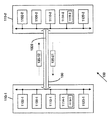
図1は、本発明の実施形態を実施することができるシステム100を示す図である。システム100は、2つのノード110−1、110−2及び通信リンク130を有する。一実施形態においてノード110は非同期である。すなわち、これらのノード110は、異なるクロック、異なる周波数等で動作しており、周波数を互いに異ならせることが可能である。さらにノード100は、送信装置1102と、受信装置1106と、キュー1110と、ドロップパケット装置1114と、制御装置1120とを有する。例示のため、名称に−1を付けたノード110の要素はノード110−1に関連し、名称に−2を付けた要素はノード110−2に関連するものとする。ノード110は通常、その要素のステータスと、その同じノード110が送信中のストリーム135のステータスおよび位置を常時監視している。本明細書における「ノード」という用語は、例示の目的でのみ使用する用語であり、ノード110は、プロセッサ、コンピュータシステム、ネットワーク装置、特定用途向け集積回路(ASIC)デバイス、プログラマブルロジックデバイス(PLD)およびそれらの均等などを含む通信設備である。ノード110はみな同じものとして説明するが、異なるものでもよいし、異なる機能を有するものでもよい。
【0009】
送信装置1102がデータを送信し、受信装置1106がデータを受信する。キュー1110は、伝送すべきデータをキューに入れる。キュー1110のデータは通常、調停プロセス(arbitration process)を用いて選択され、それは一般に調停勝者(arbitration winner)と呼ばれ、送信装置1102によって送信される。一実施形態において、データはストリームまたはパケット135の形態をとり、それらの各々は論理的には連続していても必ずしも物理的には連続していない様々な部分または断片に構成された情報の集合を含む。ノード110間において一度に複数のストリーム135を同時に伝送することができ、これらのストリームを時間インタリーブすることができる。すなわち、ストリームのすべての部分が連続するとは限らず、ある部分が1以上の他のストリームのいくつかの部分に挟まれる場合がある。例示のため、名称に−12を付けたストリーム135はそのストリームがノード110−1からノード110−2へ伝送されていることを意味し、名称に−21を付けたストリームはそのストリームがノード110−2からノード110−1へ伝送されていることを意味するものとする。トランザクションという用語はあるノード110から別のノード110へ送信されているデータの別個のストリームを意味し、トランザクションはストリームの開始境界から開始して同じストリームの終了境界で終了するものとする。一実施形態において、トランザクションは、そのトランザクションの大きさ、種類等に関する手がかりを含むそのトランザクションに関連したヘッダ埋め込み情報を含む。受信ノード110は、その受信装置1106を介してあるトランザクション中に受信されたデータ片の数をヘッダ情報に基づいてカウントし、そのトランザクションの終了境界を判定する。通常、最後のデータカウントが受信されると、トランザクションは終了する。そのため、トランザクションを開始した後にトランザクションのデータ長を変更することはできず、そうしないとデータ数がヘッダの情報と一致しなくなり、そのトランザクションに誤りが生じる可能性がある。しかしながら、ドロップパケット1118は、トランザクションの途中で送信される場合であっても、トランザクションデータの一部としてカウントされない。受信ノード110は、ドロップパケット1118を認識しても、そのトランザクションのデータ片の数をカウントする際にそれを破棄する。受信ノード110が正しいドロップパケット1118を受信する可能性を高めるため、ドロップパケット1118は送信ノード110から受信ノード110へ複数回送信することができる。例えば、1回の割込みで一連の4つのドロップパケットが送信される場合がある。
【0010】
ドロップパケット装置1114は、本明細書で開示する方法を用いて使用されるドロップパケット1118を提供する。一実施形態において、ドロップパケット1118は様々なビットを含み、そのうちの1つは、通常のデータパケットからドロップパケットを区別および分離するためのマーカとして適当な時点で使用される。マーカビットは、ドロップラインとも呼ばれる場合がある。マーカビットは、ドロップパケットマーカとして使用しない時には、他の目的に使用することができる。割込み、再送信等の様々な状況が生じた場合、制御装置1120と共に動作するドロップパケット装置1114は、キュー1110内の調停勝者を無視して、本来ならその調停勝者が受信ノードへ送信されるはずの位置でドロップパケット1118を送信する。従って、トランザクションが進行中であったり、ドロップパケットが周波数や同期の目的で必要とされていない場合であっても、そのトランザクション中の任意の時点でドロップパケット1118をストリーム135に強制的に挿入し、受信ノードへ送信することができる。その結果、データトランザクションの境界まで待機すること無くドロップパケット1118を送信することができ、例えば再送信ストリーム、通常のストリーム、アイドルストリーム等のトランザクションの種類に関係無く送信することができる。ドロップパケット1118をストリーム135に強制的に入れる場合、送信側および受信側の両方のノードの関連装置およびデータストリームを直ちに停止させ、システム100のステータスを後で使用するために保存することができる。割込みをうけたトランザクションが再開されることになるか破棄されることになるかに関らず、システム100のステータスには、例えば調停状態、キュー1110内の各ストリーム135の位置、および、通信リンク130上の各ストリーム135の位置などが含まれる。送信側および受信側の両ノードは、割込みをうけたトランザクションを破棄するか、あるいは保存された状態に基づいて中断した場所からトランザクションを継続するかを選択するオプションを有する。
【0011】
一実施形態において、ドロップパケット1118にはノード110間で送信される符号化された情報が含まれ、符号化された情報には受信ノードにいくつかのタスクを実行させるための命令が含まれる。これらの命令には、例えば、まだ受信していないが誤っているデータを受信ノードに再送信させること、受信ノード自体を他のノードで置き換えるべく停止させること、ノードの要素を置き換えることなどの要求が含まれる。ドロップパケット1118が受信ノード110に実行させる特別な命令を含む場合、受信ノードはこれらの命令を認識してそれらに留意する。そうでない場合、受信ノード110およびドロップパケット1118は、通常通り機能する。また、ドロップパケット1118はノードの周波数を同期または一致させるためにも使用することができる。例えば、ノード110−1からノード110−2へのデータの送信が12片のデータを必要とする場合であっても、受信ノード110−2では8片のデータしか使用されない場合があり、その場合、少なくとも4つのドロップパケット1118を8片のデータと共に送信し、所望の12片のデータが構成される。この4以上のドロップパケット1118は、ノード110−2に受信されると無視すなわち「除去」される。
【0012】
制御装置1120はノード110の様々なタスクを判定および実行するものであり、タスクには例えば、割り込みの実行、送信すべきデータ片の調停(arbitrate)、トランザクションの優先、中断したトランザクションの再開、システムステータスの保存、ハンドシェークの用意などが含まれる。制御装置1120は、任意の時点でノード110の送信装置および受信装置を停止させることができ、必要であればそれらの装置を再開させることもできる。また、制御装置1120は、ドロップパケットトランザクションを同期手段に対しては透過的であるがノード110に対して有用な方法で操作することができる。
【0013】
通信リンク130は、その2つの端部にある適当な要素間でデータを転送するものであり、したがってそれらの要素を適当に収容するため様々であってよい。通信リンク130の例としては、ネットワーク媒体、相互接続ファブリック、リング、クロスバ等が含まれる。一実施形態において、通信リンク130にはデータを伝送するための複数のチャネルが含まれ、あるチャネルがあるトランザクションに使用されると、そのトランザクションについてのすべてのデータ片がその同じチャネルで伝送される。さらに、チャネルのうちの1つ(例えばチャネル1320)はドロップパケット1118によって使用される優先チャネルとして機能し、例えばこれらのドロップパケットが通常のデータストリームに優先する場合に使用される。優先チャネルのデータは他のチャネルのデータよりも高い優先順位を有する。
【0014】
一実施形態による方法
図2は、一実施形態による方法を示すフロー図である。ステップ204において、ストリーム135−12およびストリーム135−21は、それぞれノード110−2およびノード110−1へ伝送中である。
【0015】
ステップ208において、ノード110−2は、ストリーム135−12の一部を受信しているときに、例えば何らかのシステムエラーやプロトコルエラーによりストリーム135−12の残りの部分を受信し続けたくないことを認識する。代りにノード110−2は、ストリーム135−12のノード110−2がまだ受信していない部分の再送信をノード110−1に要求する。例示のため、これらの部分をストリーム135−12−resendと呼ぶ。
【0016】
ステップ216において、ノード110−2はドロップパケット1118−21の準備をドロップパケット装置1114−2に要求する。このドロップパケット1118−21にはノード110−1にストリーム135−12−resendを送信させる命令が含まれる。このドロップパケット1118−21には、このドロップパケット1118−21が通常のドロップパケットではなく受信ノード110−1に対する命令を含むドロップパケットであることをノード110−1に認識させるための情報も含まれる。
【0017】
ステップ220において、ノード110−2は、ストリーム135−21のトランザクションの終了まで待機することなく、ストリーム135−21にドロップパケット1118−21を挿入する。たとえば、ストリーム135−21には10個のデータ片が含まれ、3個のデータ片が既にノード110−1へ送信されているものとする。ドロップパケット装置1114−2は、送信装置1112−2および/または制御装置1120−2と協働し、ドロップパケット1118−21が送信されなかった場合に送信されていたはずの4番目のデータ片の位置でドロップパケット1118−21が送信されるように準備する。
【0018】
ステップ224において、ドロップパケット1118−21がノード110−1に到達する。ステップ228において、ノード110−1は、ドロップパケット1118−21の情報に基づき、ドロップパケット1118−21に埋め込まれた命令、すなわちストリーム13−12−resendをノード110−2へ再送信する命令に従うべきことを認識する。
【0019】
ステップ232において、各ノード110−1および110−2は、ストリーム135−12−resendを再送信できるように適当な動作を行なう。たとえば、各ノード110−1および110−2は、その制御により対応するキュー1110およびその他の装置を停止させ、キューおよびそれらの装置のステータスを記憶し、再送信が完了した後に必要であればストリーム135−21のトランザクションを再開できるようにする。
【0020】
また、各ノード110−1およびノード110−2は、再送信を開始する前にハンドシェークも行なう。一実施形態において、一方のノード110は、追加のデータを受信または送信する準備ができると、そのことを伝えるために他方のノードへメッセージを送信する。他方のノードは、そのメッセージを受信すると受信確認を送信する。例えば、ノード110−1は、ノード110−2からデータを受信する準備ができると、データを受信する準備ができたことを知らせるメッセージをノード110−2へ送信する。これに対して、ノード110−2は、ノード110−1の準備ができたことを認識した旨を伝える確認メッセージをノード110−1へ送信し、次いで必要に応じてデータをノード110−1へ送信する。同様に、ノード110−1は、ノード110−2へデータを送信する準備ができると、データを送信する準備ができたことを知らせるメッセージをノード110−2へ送信する。それに対して、ノード110−2は、ノード110−1の準備ができたことを認識した旨を伝える確認メッセージをノード110−1へ送信するなど。
【0021】
ステップ236において、ノード110−1およびノード110−2は、ストリーム135−12−resendを伝送するため、通信リンク130を準備する。一実施形態では、ノード110−1およびノード110−2は、通信リンク130上でリンク開始を実行する。ステップ240において、ノード110−1は、ストリーム135−12−resendをノード110−2へ送信する。ステップ244において、ノード110−1およびノード11−2は、再送信を行なう前のそれぞれの対応する状態を復元し、通常の通信を再開できるようにする。
【0022】
様々な応用
上記の例では、例示の目的で、あるノード110から別のノード110への伝送には1つのストリーム135しか使用していない。しかしながら、本発明の方法は、そのような状況に限定されるのではなく、複数のストリームを含む他の状況にも適用可能である。例えば、ノード110−1からノード110−2へ複数のストリーム(例えばストリーム135A−12、135B−12および135C−12等)が一度に伝送され、同様にノード110−2からノード110−1へ複数のストリーム(例えばストリーム135A−21、135B−21および135C−21など(図示せず))が一度に伝送される状況である。ノード110−2は、データパケット1118−21をストリーム135−21に挿入したい場合、パケット135A−21、135B−21、135C−21等のうちの任意の1つを都合よく選択することができる。さらに、各ストリーム135−21は種類、大きさまたは長さが異なっていてもよく、ストリーム135A−21はストリーム135B−21とは異なるチャネルで伝送することもできる。
【0023】
さらに、上記実施例は、誤ったデータの再送信(再伝送)の状況について例示したものである。しかしながら、本発明の方法は、ストリーム135が追加の情報を伝送するために割り込みを受けた状況など、異なる状況に用いることも可能であり、そのような状況には例えば再始動、リセット、通知、許可、運用中の要素の追加および/または削除等が含まれる。例えば、ノード110−1の一部または全体は、別の部分またはノードによって置換えることができる。システム100からノードを削除することもできる。ノード110−2は、ドロップパケット1118−21に命令を挿入してノード110−1に指示することにより、ノード110−1をシャットダウンさせたり、ノード110−1の構成要素のうちのいくつかを取り除いたり、ノード110−1自体をシステム100から完全に取り除いたりすることができる。このような応用は、マイクロプロセッサおよび/またはコヒーレンシ信号送信、キャッシュライン等の、他の用途でも利用することができる。
【0024】
コンピュータシステムの概要
図3は、本発明の実施形態を実施することができるコンピュータシステム300を示すブロック図である。たとえば、コンピュータシステム300はシステム100を含むように実施することができ、ノード110として機能し、上述の方法に従って機能を実行する。一実施形態において、コンピュータシステム300は、プロセッサ304と、ランダムアクセスメモリ(RAM)308と、リードオンリメモリ(ROM)312と、記憶装置316と、通信インタフェース320とを有し、それらがすべてバス324に接続される。
【0025】
プロセッサ304は、コンピュータシステム300内でロジックを制御し、情報を処理し、活動を管理する。一実施形態において、プロセッサ304はRAM308およびROM312に格納された命令を実行し、例えば入力装置328から表示装置332へのデータの移動を管理する。
【0026】
RAM308は通常メインメモリと呼ばれ、プロセッサ304によって実行される情報および命令を一時的に記憶する。RAM308の情報は、入力装置328から取得することもできるし、あるいは、プロセッサ304によって実行される命令に必要なアルゴリズム処理の一部としてプロセッサ304によって生成することもできる。
【0027】
ROM312は情報および命令を記憶するものであり、いったんROMチップに書き込まれると読出し専用になり、変更したり消去したりすることはできない。一実施形態において、ROM312には、コンピュータシステム300の設定および初期動作のためのコマンドが記憶される。
【0028】
記憶装置316はフロッピー(R)ディスク、ディスクドライブまたはテープドライブ等であり、コンピュータシステム300によって使用される情報を長期間記憶する。
【0029】
通信インタフェース320は、コンピュータシステム300を他のコンピュータや装置とインタフェースする。通信インタフェース320は、例えば、モデム、統合デジタル通信網(ISDN)カード、ローカルエリアネットワーク(LAN)ポート等である。当業者であれば、モデムやISDNカードが電話回線を介したデータ通信を提供するものであり、LANポートがLANを介したデータ通信を提供するものであることが分かるであろう。また、通信インタフェース320は、無線通信も可能にする。
【0030】
バス324は、コンピュータシステム300によって使用される情報を伝達するためのいかなる通信手段であってもよい。図3の例の場合、バス324は、プロセッサ304、RAM308、ROM312、記憶装置316、通信インタフェース320等の間でデータを伝達する媒体である。
【0031】
コンピュータシステム300は通常、入力装置328、表示装置332およびカーソル制御装置336に接続される。入力装置328は英数字その他のキーを含むキーボード等であり、情報やコマンドをプロセッサ304に伝達する。表示装置322はブラウン管(CRT)等であり、コンピュータシステム300のユーザに情報を表示する。カーソル制御装置336はマウス、トラックボールまたはカーソル方向キー等であり、方向情報およびコマンドをプロセッサ304へ伝達するとともに、表示装置332上のカーソル移動を制御する。
【0032】
コンピュータシステム300は、1以上のネットワークを通して他のコンピュータまたは装置と通信することができる。例えば、コンピュータシステム300は、通信インタフェース320を用いることにより、ネットワーク340を介してプリンタ348に接続された別のコンピュータ344と通信したり、あるいはワールドワイドウェブ352を介してサーバ356と通信したりすることができる。ワールドワイドウェブ352は一般に「インターネット」と呼ばれる。代替として、コンピュータシステム300はネットワーク340を介してインタネット352にアクセスすることもできる。
【0033】
コンピュータシステム300を用いて上記の方法を実施することができる。様々な実施形態において、プロセッサ304は、RAM308に取得した命令を実行することにより本方法のステップを実行する。代替実施形態では、固定配線回路をソフトウェア命令の代わりにあるいはソフトウェアと組み合せて使用することにより、上記の方法を実施することもできる。したがって、本発明の実施形態は、ソフトウェア、ハードウェアまたは回路のうちのいずれか1つに限定されることはなく、またその組合せにも限定されない。
【0034】
プロセッサ304によって実行される命令は、1以上のコンピュータ読取可能媒体に格納し、それらを用いて持ち運ぶことができる。コンピュータ読取可能媒体は、コンピュータが情報を読み出すことの可能な任意の媒体を意味している。コンピュータ読取可能媒体には、例えばフロッピー(R)ディスク、ハードディスク、ジップ(zip)ドライブカートリッジ、磁気テープまたは任意の他の磁気媒体、CD−ROM、CD−RAM、DVD−ROM、DVD−RAMまたは任意の他の光媒体、紙テープ、パンチカードまたは穴のパターンを有する任意の他の物理媒体、RAM、ROM、EPROMまたは任意の他のメモリチップまたはカートリッジなどが含まれる。また、コンピュータ読取可能媒体は、同軸ケーブル、銅線、光ファイバ、音波または光波等であってもよい。例として、プロセッサ304によって実行される命令は、1以上のソフトウェアプログラムの形態をとり、バス324を介してコンピュータシステム300とインタフェースしているCD−ROMに最初に格納される。コンピュータシステム300は、これらの命令をRAM308にロードし、いくつかの命令を実行し、通信インタフェース320、モデムおよび電話回線を介していくつかの命令をネットワーク(例えばネットワーク340、インターネット352等)へ送信する。リモートコンピュータはネットワークケーブルを通してデータを受信し、受信した命令を実行し、そのデータをコンピュータシステム300に送信して記憶装置316に格納する。
【0035】
上記の詳細な説明において、本発明は、その特定の実施形態を参照して説明されている。しかしながら、本発明の広い思想および範囲から逸脱することなく種々の変更および変形を行うことが可能であることは明らかであろう。本発明の技術は、システム、装置、機器あるいはそれらの均等、方法やプロセス、コンピュータ読取可能媒体等、いずれの形態としても実施することができる。従って、本明細書および図面は、限定するものではなく例示するものと考えなければならない。
【0036】
以下においては、本発明の種々の構成要件の組み合わせからなる例示的な実施態様を示す。
1.第2のノード(110)から第1のノード(110)へ情報を送信する方法であって、
前記第1のノード(110)と前記第2のノード(110)との間に通信リンク(130)を確立するステップと、
前記第1のノード(110)と第2のノード(110)との間の通信リンクにおける1以上のデータトランザクションの送信を可能にするステップと、
前記第2のノード(110)から前記第1のノード(110)へ送信中のデータトランザクションのデータストリーム(135)を識別するステップと、
前記トランザクションを停止させ、前記情報を前記データストリーム(135)に挿入し、これによって前記情報を前記第2のノード(110)から前記データストリーム(135)を介して前記第1のノード(110)へ送信するステップと、
から構成され、
前記データトランザクションが前記第2のノード(110)から開始して前記第1のノードまでである場合、前記情報が該データトランザクションの一部ではないものである方法。
2.前記第1のノード(110)と前記第2のノード(110)とを2つの異なる周波数で動作させるステップをさらに含む、上記1の方法。
3.前記第1のノード(110)にタスクを実行させるための命令を前記情報に含めるステップをさらに含む、上記1の方法。
4.前記情報を前記第1のノード(110)と前記第2のノード(110)との同期をとるために通常用いられるパケットに入れて送信するステップをさらに含む、上記1の方法。
5.前記情報を前記第2のノード(110)から前記第1のノード(110)へ送信中のデータストリームの一部としてカウントされないパケットに入れて送信するステップをさらに含む、上記1の方法。
6.前記第1のノード(110)および前記第2のノード(110)が、コンピュータシステム、ネットワーク装置、マイクロプロセッサおよび電子チップからなるグループの中から選択される、上記1の方法。
7.前記トランザクションを停止させた時点での該トランザクションの状態を保存し、保存された前記状態に基いて前記トランザクションを再開させるステップをさらに含む、上記1の方法。
8.第2のノード(110)から第1のノード(110)へ情報を送信する方法であって、
前記第1のノード(110)と前記第2のノード(110)との間に通信リンク(130)を確立するステップと、
前記第2のノード(110)から前記データリンク(130)を介して第1のノード(110)へ送信中のデータトランザクションであってヘッダおよび複数のデータ片(135)を含むデータトランザクションを識別するステップと、
前記第1のノード(110)において前記データ片(135)をカウントし、前記ヘッダのデータに基いて前記トランザクションの終わりを識別するステップと、
前記データトランザクションを停止し、前記情報を含むパケットを前記第1のノード(110)へ向けて前記通信リンク(130)に送信するステップと、
前記第1のノード(130)において前記パケットが前記トランザクションの一部ではないものとしてカウントするステップと、
からなる方法。
9.前記第1のノード(110)と前記第2のノード(110)とを2つの異なる周波数で動作させるステップをさらに含む、上記8の方法。
10.前記第1のノード(110)にタスクを実行させるための命令を前記情報に含めるステップをさらに含む、上記8の方法。
【0037】
【発明の効果】
本発明は、上記の構成により、トランザクションの途中でデータを送信することが可能になる。
【図面の簡単な説明】
【図1】本発明の実施形態を実施することができるシステムを示す図である。
【図2】一実施形態による方法を示すフロー図である。
【図3】本発明の実施形態を実施することができるコンピュータシステムを示す図である。
【符号の説明】
110 ノード
130 通信リンク
135 データストリーム[0001]
BACKGROUND OF THE INVENTION
The present invention relates generally to transmitting data, and more particularly to transmitting information using ongoing data transactions.
[0002]
[Prior art]
Data is often transmitted between different nodes such as computer systems, network equipment, microprocessors, semiconductor chips, electronic chips, and the like. Data is transmitted at the boundary by various methods, but is not transmitted in the middle of a data transaction. Thus, if a transaction is in progress, the additional data must wait until the next boundary of the transaction, even if some additional data is desired to be transmitted, such as by an interrupt. In such a situation, means including status bits, support logic, control logic, etc. may be required to constantly monitor transaction boundaries. Traditional retransmission algorithms may have to be modified to support interrupting the stream during retransmission. Thus, complexity and other problems are added to the system. For asynchronous systems, it is more difficult to find the location of transaction boundaries.
[0003]
Based on the above, there is clearly a need to provide means to solve the above disadvantages and related problems.
[0004]
[Problems to be solved by the invention]
An object of the present invention is to provide a method for transmitting additional information using an ongoing data transaction.
[0005]
[Means for Solving the Problems]
The present invention, in various embodiments, provides techniques for transmitting additional information using ongoing data transactions. In one exemplary embodiment, two asynchronous nodes send data to each other. In one transaction related to the transmission of data to the second node of the first node, the second node receiving a portion of the data may receive a different portion of the data being transmitted such as various errors. Recognize fraud due to The second node then immediately requests the first node to retransmit the currently erroneous data to be received. In one embodiment, the second node inserts this request into the data stream being transmitted from the second node to the first node. The second node does not need to wait until the data transaction boundary, and in one embodiment, this request is embedded in a “drop packet”.
[0006]
The present invention will be described by way of example and is not intended to be limiting, and like reference numerals refer to like elements in the accompanying drawings.
[0007]
DETAILED DESCRIPTION OF THE INVENTION
In the following description, for the purposes of explanation, numerous specific details are set forth in order to provide a thorough understanding of the present invention. However, it will be apparent to one skilled in the art that the present invention may be practiced without these specific details. In other instances, well-known structures and devices are shown in block diagram form in order to avoid obscuring the present invention.
[0008]
Hardware overview
FIG. 1 is a diagram illustrating a
[0009]
The transmission apparatus 1102 transmits data, and the reception apparatus 1106 receives data. The queue 1110 queues data to be transmitted. The data in the queue 1110 is typically selected using an arbitration process, which is commonly referred to as an arbitration winner and is transmitted by the transmitter 1102. In one embodiment, the data takes the form of a stream or packet 135, each of which is a collection of information organized into various parts or pieces that are logically contiguous but not necessarily physically contiguous. including. Multiple streams 135 can be transmitted at the same time between nodes 110 and these streams can be time interleaved. That is, not all parts of a stream are continuous, and a part may be sandwiched between several parts of one or more other streams. For purposes of illustration, a stream 135 with a name of −12 means that the stream is being transmitted from node 110-1 to node 110-2, and a stream with a name of −21 has a stream of node 110 -2 to the node 110-1. The term transaction refers to a separate stream of data being transmitted from one node 110 to another node 110, and the transaction shall begin at the start boundary of the stream and end at the end boundary of the same stream. In one embodiment, the transaction includes header embedding information associated with the transaction, including clues about the size, type, etc. of the transaction. The receiving node 110 counts the number of data pieces received during a transaction via the receiving device 1106 based on the header information, and determines the end boundary of the transaction. Normally, the transaction ends when the last data count is received. For this reason, the data length of the transaction cannot be changed after the transaction is started. Otherwise, the number of data does not match the information in the header, and an error may occur in the transaction. However, the drop packet 1118 is not counted as part of the transaction data even if it is transmitted in the middle of a transaction. Even if the receiving node 110 recognizes the drop packet 1118, it discards it when counting the number of data pieces of the transaction. In order to increase the likelihood that the receiving node 110 will receive the correct drop packet 1118, the drop packet 1118 can be sent from the sending node 110 to the receiving node 110 multiple times. For example, a series of four drop packets may be transmitted in one interrupt.
[0010]
Drop packet device 1114 provides drop packet 1118 for use with the methods disclosed herein. In one embodiment, the drop packet 1118 includes various bits, one of which is used at a suitable time as a marker to distinguish and separate the drop packet from the normal data packet. The marker bit may also be called a drop line. The marker bit can be used for other purposes when not used as a drop packet marker. When various situations such as interruption and retransmission occur, the drop packet device 1114 operating together with the control device 1120 ignores the arbitration winner in the queue 1110, and the arbitration winner should be transmitted to the receiving node. A drop packet 1118 is transmitted at the position. Therefore, even if a transaction is in progress or a drop packet is not required for frequency or synchronization purposes, the drop packet 1118 is forcibly inserted into the stream 135 at any point in the transaction. , Can be sent to the receiving node. As a result, the drop packet 1118 can be transmitted without waiting for the boundary of the data transaction, and can be transmitted regardless of the type of transaction such as a retransmission stream, a normal stream, and an idle stream. If the drop packet 1118 is forced into the stream 135, the associated device and data stream at both the sending and receiving nodes can be immediately stopped and the status of the
[0011]
In one embodiment, the drop packet 1118 includes encoded information that is transmitted between the nodes 110, and the encoded information includes instructions for causing the receiving node to perform several tasks. These instructions include, for example, a request to retransmit data that has not yet been received but is erroneous to the receiving node, stop the receiving node itself from being replaced by another node, or replace a node element. Is included. If the drop packet 1118 includes special instructions that cause the receiving node 110 to execute, the receiving node will recognize these instructions and note them. Otherwise, the receiving node 110 and the drop packet 1118 function normally. The drop packet 1118 can also be used to synchronize or match the node frequency. For example, even if transmission of data from the node 110-1 to the node 110-2 requires 12 pieces of data, the receiving node 110-2 may use only 8 pieces of data. At least four drop packets 1118 are transmitted along with 8 pieces of data to form the desired 12 pieces of data. These four or more dropped packets 1118 are ignored or “removed” when received by node 110-2.
[0012]
The control device 1120 determines and executes various tasks of the node 110. Examples of the tasks include execution of interrupts, arbitration of data pieces to be transmitted, priority of transactions, resumption of interrupted transactions, system This includes saving status and preparing handshaking. The control device 1120 can stop the transmission device and the reception device of the node 110 at any time, and can restart those devices if necessary. Also, the control device 1120 can operate the drop packet transaction in a useful manner for the node 110 while being transparent to the synchronization means.
[0013]
The
[0014]
Method according to one embodiment
FIG. 2 is a flow diagram illustrating a method according to one embodiment. In
[0015]
In
[0016]
In step 216, the node 110-2 requests the drop packet device 1114-2 to prepare the drop packet 1118-21. The drop packet 1118-21 includes a command for causing the node 110-1 to transmit the stream 135-12-resend. The drop packet 1118-21 includes information for causing the node 110-1 to recognize that the drop packet 1118-21 is not a normal drop packet but a drop packet including an instruction for the receiving node 110-1. .
[0017]
In
[0018]
In step 224, the drop packet 1118-21 reaches the node 110-1. In step 228, the node 110-1 should follow the instruction embedded in the drop packet 1118-21, that is, the instruction to retransmit the stream 13-12-resend to the node 110-2 based on the information of the drop packet 1118-21. Recognize that.
[0019]
In
[0020]
Each node 110-1 and node 110-2 also perform handshaking before starting retransmission. In one embodiment, one node 110 sends a message to the other node to communicate when it is ready to receive or send additional data. When the other node receives the message, it sends a receipt confirmation. For example, when node 110-1 is ready to receive data from node 110-2, it sends a message to node 110-2 informing it that it is ready to receive data. In response to this, the node 110-2 transmits a confirmation message notifying that the node 110-1 has been prepared to the node 110-1, and then transmitting data to the node 110-1 as necessary. Send. Similarly, when the node 110-1 is ready to transmit data to the node 110-2, the node 110-1 transmits a message notifying that the data is ready to be transmitted to the node 110-2. On the other hand, the node 110-2 transmits a confirmation message notifying that it has recognized that the node 110-1 is ready to the node 110-1.
[0021]
In
[0022]
Various applications
In the above example, only one stream 135 is used for transmission from one node 110 to another 110 for illustrative purposes. However, the method of the present invention is not limited to such a situation, but can be applied to other situations involving a plurality of streams. For example, a plurality of streams (for example, streams 135A-12, 135B-12, and 135C-12) are transmitted from the node 110-1 to the node 110-2 at the same time, and similarly, a plurality of streams are transmitted from the node 110-2 to the node 110-1. Stream (for example, streams 135A-21, 135B-21, and 135C-21 (not shown)) are transmitted at a time. Node 110-2 may conveniently select any one of packets 135A-21, 135B-21, 135C-21, etc., when it wants to insert data packet 1118-21 into stream 135-21. Furthermore, each stream 135-21 may be different in type, size, or length, and stream 135A-21 may be transmitted on a different channel than stream 135B-21.
[0023]
Further, the above embodiment illustrates the situation of erroneous data retransmission (retransmission). However, the method of the present invention can also be used in different situations, such as situations where stream 135 has been interrupted to carry additional information, such as restart, reset, notification, Includes permission, addition and / or deletion of elements in operation. For example, part or all of the node 110-1 can be replaced by another part or node. Nodes can also be deleted from the
[0024]
Computer system overview
FIG. 3 is a block diagram that illustrates a
[0025]
The
[0026]
The
[0027]
The
[0028]
The
[0029]
The
[0030]
[0031]
[0032]
[0033]
The
[0034]
The instructions executed by
[0035]
In the foregoing detailed description, the invention has been described with reference to specific embodiments thereof. However, it will be apparent that various changes and modifications can be made without departing from the broad spirit and scope of the invention. The technology of the present invention can be implemented in any form such as a system, apparatus, device, or equivalents thereof, a method or process, a computer-readable medium, or the like. Accordingly, the specification and drawings are to be regarded as illustrative rather than limiting.
[0036]
In the following, exemplary embodiments consisting of combinations of various constituents of the present invention are shown.
1. A method for transmitting information from a second node (110) to a first node (110), comprising:
Establishing a communication link (130) between the first node (110) and the second node (110);
Enabling transmission of one or more data transactions over a communication link between the first node (110) and the second node (110);
Identifying a data stream (135) of a data transaction being transmitted from the second node (110) to the first node (110);
Stop the transaction and insert the information into the data stream (135), thereby transferring the information from the second node (110) via the data stream (135) to the first node (110). Sending to
Consisting of
The method wherein the information is not part of the data transaction if the data transaction is from the second node (110) to the first node.
2. The method of claim 1, further comprising the step of operating the first node (110) and the second node (110) at two different frequencies.
3. The method of claim 1, further comprising the step of including in the information instructions for causing the first node (110) to perform a task.
4). The method of claim 1, further comprising the step of transmitting the information in a packet normally used to synchronize the first node (110) and the second node (110).
5). The method of claim 1, further comprising the step of transmitting the information in packets that are not counted as part of a data stream being transmitted from the second node (110) to the first node (110).
6). The method of claim 1, wherein the first node (110) and the second node (110) are selected from the group consisting of a computer system, a network device, a microprocessor and an electronic chip.
7). The method of claim 1, further comprising: saving a state of the transaction at the time of stopping the transaction, and resuming the transaction based on the saved state.
8). A method for transmitting information from a second node (110) to a first node (110), comprising:
Establishing a communication link (130) between the first node (110) and the second node (110);
Identifying a data transaction being transmitted from the second node (110) to the first node (110) via the data link (130) and including a header and a plurality of data pieces (135) Steps,
Counting the data pieces (135) at the first node (110) and identifying the end of the transaction based on the data in the header;
Stopping the data transaction and sending a packet containing the information to the first link (110) to the communication link (130);
Counting at the first node (130) that the packet is not part of the transaction;
A method consisting of:
9. 9. The method of claim 8, further comprising operating the first node (110) and the second node (110) at two different frequencies.
10. 9. The method of claim 8, further comprising the step of including in the information an instruction for causing the first node (110) to perform a task.
[0037]
【The invention's effect】
According to the above configuration, the present invention can transmit data in the middle of a transaction.
[Brief description of the drawings]
FIG. 1 illustrates a system in which embodiments of the present invention can be implemented.
FIG. 2 is a flow diagram illustrating a method according to one embodiment.
FIG. 3 illustrates a computer system that can implement embodiments of the present invention.
[Explanation of symbols]
110 nodes
130 Communication link
135 Data Stream
Claims (6)
前記第1のノード(110-1)と前記第2のノード(110-2)の間に、双方向通信のための通信リンク(130)を確立するステップと、
前記第1のノード(110-1)から前記第2のノード(110-2)への第1のデータストリーム(135-12)の中に、前記第2のノード(110-2)によって受信されるべきデータ片のカウント数を含めるステップと、
前記第2のノード(110-2)から前記第1のノード(110-1)への第2のデータストリーム(135-21)を停止させるステップと、
前記第2のデータストリーム(135-21)を停止させた時点での前記第2のデータストリーム(135-21)の状態を保存するステップと、
停止された前記第2のデータストリーム(135-21)の中に制御情報を挿入し、該制御情報により、前記第1のノード(110-1)に特定のタスクの実行を命じるステップと、
保存された前記状態に基いて前記第2のデータストリーム(135-21)を再開させるステップと
を含み、前記制御情報が、前記第1のノード(110-1)によって受信されるべきデータ片の数の一部としてカウントされず、
前記特定のタスクは、前記第1のノード(110-1)による誤ったデータの再送信、前記第1のノード(110-1)の停止、及び前記第1のノード(110-1)の要素の置換のうちのいずれか一つである、方法。A method for transmitting information from a first node (110-1) to the second node (110-2),
Establishing a communication link (130) for bidirectional communication between the first node (110-1) and the second node (110-2);
Some from the first node (110-1) of the first data stream (135-12) into the second node (110-2), is received by the second node (110- 2) Including a count of the number of data pieces to be
Stopping the second data stream (135-21) from the second node (110-2) to the first node (110-1);
Storing the state of said second data stream (135-21) at the time of stopping the second data stream (135-21),
Inserting control information into the stopped second data stream (135-21) and instructing the first node (110-1) to execute a specific task according to the control information;
Resuming the second data stream (135-21) based on the stored state, and wherein the control information is a data fragment to be received by the first node (110-1). Not counted as part of the number,
The specific task includes retransmission of erroneous data by the first node (110-1), stopping of the first node (110-1), and elements of the first node (110-1) A method that is any one of the substitutions.
Applications Claiming Priority (2)
| Application Number | Priority Date | Filing Date | Title |
|---|---|---|---|
| US10/029733 | 2001-12-18 | ||
| US10/029,733 US20030115352A1 (en) | 2001-12-18 | 2001-12-18 | Sending information using an in-progress transaction |
Publications (3)
| Publication Number | Publication Date |
|---|---|
| JP2003204367A JP2003204367A (en) | 2003-07-18 |
| JP2003204367A5 JP2003204367A5 (en) | 2006-02-16 |
| JP4536317B2 true JP4536317B2 (en) | 2010-09-01 |
Family
ID=21850581
Family Applications (1)
| Application Number | Title | Priority Date | Filing Date |
|---|---|---|---|
| JP2002358991A Expired - Fee Related JP4536317B2 (en) | 2001-12-18 | 2002-12-11 | Sending information using an ongoing transaction |
Country Status (2)
| Country | Link |
|---|---|
| US (1) | US20030115352A1 (en) |
| JP (1) | JP4536317B2 (en) |
Families Citing this family (4)
| Publication number | Priority date | Publication date | Assignee | Title |
|---|---|---|---|---|
| US8055784B2 (en) * | 2008-07-07 | 2011-11-08 | Disney Enterprises, Inc. | Content navigation module for managing delivery of content to computing devices and method therefor |
| US11900156B2 (en) | 2019-09-24 | 2024-02-13 | Speedata Ltd. | Inter-thread communication in multi-threaded reconfigurable coarse-grain arrays |
| US11354157B2 (en) * | 2020-04-28 | 2022-06-07 | Speedata Ltd. | Handling multiple graphs, contexts and programs in a coarse-grain reconfigurable array processor |
| US11175922B1 (en) | 2020-04-28 | 2021-11-16 | Speedata Ltd. | Coarse-grain reconfigurable array processor with concurrent handling of multiple graphs on a single grid |
Citations (6)
| Publication number | Priority date | Publication date | Assignee | Title |
|---|---|---|---|---|
| JPH06222916A (en) * | 1993-01-25 | 1994-08-12 | Nec Corp | On-line real-time processor |
| JPH10285234A (en) * | 1997-04-01 | 1998-10-23 | Sony Corp | Signal processing circuit and its method |
| JPH10285241A (en) * | 1997-04-01 | 1998-10-23 | Sony Corp | Signal processing circuit |
| JP2000293454A (en) * | 1999-04-05 | 2000-10-20 | Toshiba Corp | Equipment and method for data communication, and recording medium |
| JP2001211195A (en) * | 2000-01-25 | 2001-08-03 | Fujitsu Ltd | Data communication system |
| JP2001216259A (en) * | 2000-02-04 | 2001-08-10 | Hitachi Ltd | Multiprocessor system and transaction control method thereof |
Family Cites Families (10)
| Publication number | Priority date | Publication date | Assignee | Title |
|---|---|---|---|---|
| US5949799A (en) * | 1996-12-27 | 1999-09-07 | Cypress Semiconductor Corp. | Minimum-latency data mover with auto-segmentation and reassembly |
| US5940839A (en) * | 1997-04-04 | 1999-08-17 | Hewlett-Packard Company | Fault-tolerant system and method of managing transaction failures in hierarchies |
| US5914472A (en) * | 1997-09-23 | 1999-06-22 | At&T Corp | Credit card spending authorization control system |
| US6026444A (en) * | 1998-06-24 | 2000-02-15 | Siemens Pyramid Information Systems, Inc. | TORUS routing element error handling and self-clearing with link lockup prevention |
| US6266702B1 (en) * | 1998-09-28 | 2001-07-24 | Raytheon Company | Method and apparatus to insert and extract data from a plurality of slots of data frames by using access table to identify network nodes and their slots for insertion and extraction data |
| US6256641B1 (en) * | 1998-12-15 | 2001-07-03 | Hewlett-Packard Company | Client transparency system and method therefor |
| US6748442B1 (en) * | 1998-12-21 | 2004-06-08 | Advanced Micro Devices, Inc. | Method and apparatus for using a control signal on a packet based communication link |
| US6389431B1 (en) * | 1999-08-25 | 2002-05-14 | Hewlett-Packard Company | Message-efficient client transparency system and method therefor |
| US6772217B1 (en) * | 2000-08-23 | 2004-08-03 | International Business Machines Corporation | Internet backbone bandwidth enhancement by initiating an additional data stream when individual bandwidth are approximately equal to the backbone limit |
| US6708260B2 (en) * | 2002-03-14 | 2004-03-16 | Hewlett-Packard Development Company, L.P. | Managing data in a queue |
-
2001
- 2001-12-18 US US10/029,733 patent/US20030115352A1/en not_active Abandoned
-
2002
- 2002-12-11 JP JP2002358991A patent/JP4536317B2/en not_active Expired - Fee Related
Patent Citations (6)
| Publication number | Priority date | Publication date | Assignee | Title |
|---|---|---|---|---|
| JPH06222916A (en) * | 1993-01-25 | 1994-08-12 | Nec Corp | On-line real-time processor |
| JPH10285234A (en) * | 1997-04-01 | 1998-10-23 | Sony Corp | Signal processing circuit and its method |
| JPH10285241A (en) * | 1997-04-01 | 1998-10-23 | Sony Corp | Signal processing circuit |
| JP2000293454A (en) * | 1999-04-05 | 2000-10-20 | Toshiba Corp | Equipment and method for data communication, and recording medium |
| JP2001211195A (en) * | 2000-01-25 | 2001-08-03 | Fujitsu Ltd | Data communication system |
| JP2001216259A (en) * | 2000-02-04 | 2001-08-10 | Hitachi Ltd | Multiprocessor system and transaction control method thereof |
Also Published As
| Publication number | Publication date |
|---|---|
| JP2003204367A (en) | 2003-07-18 |
| US20030115352A1 (en) | 2003-06-19 |
Similar Documents
| Publication | Publication Date | Title |
|---|---|---|
| CA1304826C (en) | Terminal device session management protocol | |
| TWI343007B (en) | Point-to-point link negotiation method and apparatus | |
| US7978705B2 (en) | Self-healing link sequence counts within a circular buffer | |
| KR950014178B1 (en) | Input/output network for computer system | |
| US5165020A (en) | Terminal device session management protocol | |
| JP3913552B2 (en) | Auto-negotiation method and auto-negotiation device for high-speed links | |
| CN103905300B (en) | A kind of data message sending method, equipment and system | |
| JPH0637804A (en) | System and method for transmission of data frame | |
| JP2000517140A (en) | Distributed network synchronization system | |
| US5053946A (en) | Token ring network having token request mechanism | |
| US6556953B2 (en) | Automatic testing of redundant switching element and automatic switchover | |
| KR20000006114A (en) | Method and apparatus for providing a network interface | |
| JP4536317B2 (en) | Sending information using an ongoing transaction | |
| US8930557B2 (en) | Data transmission with constant data rate | |
| JP2986798B2 (en) | Data transmission control method and data communication device | |
| JPH10308791A (en) | Method and equipment for data communication and data communication program recording medium | |
| JPH117434A (en) | System for processing quick arrival message in ansyncronous data communication system for plural nodes | |
| JP3569149B2 (en) | Communication control device | |
| JP2001094537A (en) | Transmission device equipped with error processing function and error processing method | |
| JP2002281034A (en) | Information transfer device | |
| JP2008148181A (en) | Communication apparatus and communication control method | |
| JPH10154116A (en) | Data transfer method | |
| JP3343905B2 (en) | HDLC high-speed communication system | |
| JPS61292444A (en) | Communication control system | |
| US20060140122A1 (en) | Link retry per virtual channel |
Legal Events
| Date | Code | Title | Description |
|---|---|---|---|
| A521 | Request for written amendment filed |
Free format text: JAPANESE INTERMEDIATE CODE: A523 Effective date: 20051130 |
|
| A621 | Written request for application examination |
Free format text: JAPANESE INTERMEDIATE CODE: A621 Effective date: 20051130 |
|
| A521 | Request for written amendment filed |
Free format text: JAPANESE INTERMEDIATE CODE: A523 Effective date: 20051228 |
|
| A977 | Report on retrieval |
Free format text: JAPANESE INTERMEDIATE CODE: A971007 Effective date: 20080610 |
|
| A131 | Notification of reasons for refusal |
Free format text: JAPANESE INTERMEDIATE CODE: A131 Effective date: 20080624 |
|
| A601 | Written request for extension of time |
Free format text: JAPANESE INTERMEDIATE CODE: A601 Effective date: 20080924 |
|
| A602 | Written permission of extension of time |
Free format text: JAPANESE INTERMEDIATE CODE: A602 Effective date: 20080929 |
|
| A521 | Request for written amendment filed |
Free format text: JAPANESE INTERMEDIATE CODE: A523 Effective date: 20081224 |
|
| A131 | Notification of reasons for refusal |
Free format text: JAPANESE INTERMEDIATE CODE: A131 Effective date: 20090224 |
|
| A601 | Written request for extension of time |
Free format text: JAPANESE INTERMEDIATE CODE: A601 Effective date: 20090525 |
|
| A602 | Written permission of extension of time |
Free format text: JAPANESE INTERMEDIATE CODE: A602 Effective date: 20090528 |
|
| A521 | Request for written amendment filed |
Free format text: JAPANESE INTERMEDIATE CODE: A523 Effective date: 20090821 |
|
| A02 | Decision of refusal |
Free format text: JAPANESE INTERMEDIATE CODE: A02 Effective date: 20091117 |
|
| A521 | Request for written amendment filed |
Free format text: JAPANESE INTERMEDIATE CODE: A523 Effective date: 20100317 |
|
| A911 | Transfer to examiner for re-examination before appeal (zenchi) |
Free format text: JAPANESE INTERMEDIATE CODE: A911 Effective date: 20100324 |
|
| A131 | Notification of reasons for refusal |
Free format text: JAPANESE INTERMEDIATE CODE: A131 Effective date: 20100413 |
|
| A521 | Request for written amendment filed |
Free format text: JAPANESE INTERMEDIATE CODE: A523 Effective date: 20100525 |
|
| TRDD | Decision of grant or rejection written | ||
| A01 | Written decision to grant a patent or to grant a registration (utility model) |
Free format text: JAPANESE INTERMEDIATE CODE: A01 Effective date: 20100608 |
|
| A01 | Written decision to grant a patent or to grant a registration (utility model) |
Free format text: JAPANESE INTERMEDIATE CODE: A01 |
|
| A61 | First payment of annual fees (during grant procedure) |
Free format text: JAPANESE INTERMEDIATE CODE: A61 Effective date: 20100616 |
|
| FPAY | Renewal fee payment (event date is renewal date of database) |
Free format text: PAYMENT UNTIL: 20130625 Year of fee payment: 3 |
|
| R150 | Certificate of patent or registration of utility model |
Free format text: JAPANESE INTERMEDIATE CODE: R150 |
|
| LAPS | Cancellation because of no payment of annual fees |