JP3913552B2 - Auto-negotiation method and auto-negotiation device for high-speed links - Google Patents
Auto-negotiation method and auto-negotiation device for high-speed links Download PDFInfo
- Publication number
- JP3913552B2 JP3913552B2 JP2002006515A JP2002006515A JP3913552B2 JP 3913552 B2 JP3913552 B2 JP 3913552B2 JP 2002006515 A JP2002006515 A JP 2002006515A JP 2002006515 A JP2002006515 A JP 2002006515A JP 3913552 B2 JP3913552 B2 JP 3913552B2
- Authority
- JP
- Japan
- Prior art keywords
- page
- auto
- transmission
- negotiation
- transmission device
- Prior art date
- Legal status (The legal status is an assumption and is not a legal conclusion. Google has not performed a legal analysis and makes no representation as to the accuracy of the status listed.)
- Expired - Fee Related
Links
Images


Classifications
-
- H—ELECTRICITY
- H04—ELECTRIC COMMUNICATION TECHNIQUE
- H04L—TRANSMISSION OF DIGITAL INFORMATION, e.g. TELEGRAPHIC COMMUNICATION
- H04L12/00—Data switching networks
- H04L12/28—Data switching networks characterised by path configuration, e.g. LAN [Local Area Networks] or WAN [Wide Area Networks]
-
- H—ELECTRICITY
- H04—ELECTRIC COMMUNICATION TECHNIQUE
- H04L—TRANSMISSION OF DIGITAL INFORMATION, e.g. TELEGRAPHIC COMMUNICATION
- H04L9/00—Cryptographic mechanisms or cryptographic arrangements for secret or secure communications; Network security protocols
- H04L9/40—Network security protocols
-
- H—ELECTRICITY
- H04—ELECTRIC COMMUNICATION TECHNIQUE
- H04L—TRANSMISSION OF DIGITAL INFORMATION, e.g. TELEGRAPHIC COMMUNICATION
- H04L69/00—Network arrangements, protocols or services independent of the application payload and not provided for in the other groups of this subclass
- H04L69/24—Negotiation of communication capabilities
Landscapes
- Engineering & Computer Science (AREA)
- Computer Security & Cryptography (AREA)
- Computer Networks & Wireless Communication (AREA)
- Signal Processing (AREA)
- Small-Scale Networks (AREA)
- Communication Control (AREA)
Description
【0001】
【発明の属する技術分野】
本発明は高速イーサネット(Ethernet)に係り、特に、1000ベース(BASE)-T標準を利用するギガビットイーサネットでの高速リンクのための自動-交渉方法及び自動-交渉装置に関する。
【0002】
【従来の技術】
一般に、イーサネットは特定区域内に設けられた情報通信網のLAN(Local Area Network)に使われるネットワークのモデルであって、IEEE(Institute of Electrical and Electronic Engineers)で採択した同軸ケーブルネットワークをいう。現在ではイーサネットが高速化されるにつれてギガビットイーサネットが広く利用されている。ギガビットイーサネットはIEEE802.3で定義され、特に1000Base-T標準は同軸ケーブルを利用した標準プロトコルのうちの一つであって、IEEE802.3ab仕様を定義する。ギガビットイーサネットの機能のうち伝送デバイス、すなわち、相手局(remote)と本局(local)との間のリンクのために、自動-交渉(auto-negotiation:以下、ANという)機能が必須的に追加されて使われる。すなわち、AN機能は相手局と本局との間にリンクが結成される前に、相手局と本局との通信速度と動作モードを決定し、これに基づいて通信を行える機能をいう。ギガビットイーサネット、すなわち、1000Mbpsではない10/100Mbpsイーサネットでは本局がAN機能を有しなくても、並列検出機能により通信速度やモードを決定できた。ここで、並列検出機能とは、AN機能を使用しないデバイスとAN機能を使用するデバイスとが互いに連結されている時、AN機能を使用しないデバイスによりノーマル伝送モードであることが感知されてノーマルモードに自動転換される機能をいう。しかし、1000Mbps速度のイーサネットの場合には必ずAN機能により伝送デバイスの間の通信速度とモードが決定されねばならない。また、ギガビットイーサネットではマスタ/スレーブ(Master/Slave:以下、M/Sと略称)機能が追加されている。すなわち、互いに連結されるデバイスのうち一つはマスタの役割を行わねばならなく、他の一つはスレーブの役割を行わねばならないために、AN機能が必須に使われる。
【0003】
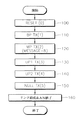
図1は、従来の1000ベース-T標準を利用する高速イーサネットでのAN方法のうち送信過程を説明するためのフローチャートである。図1を参照すれば従来では1000ベース-T標準でAN機能を行うために、伝送デバイスの間に5段階のページ伝送段階を経なければならない。具体的に、伝送デバイスは初期リセット(第100段階)後に通信規格及び基本的な通信速度を示すベースページ(Base Page: 以下、BPという)を送信する(第110段階)。第110段階後に1000Mbpsの伝送が可能であるということと、二つの非形式ページ(unformatted message: 以下、UPという)が以後に伝送されることを知らせるメッセージページ(Message Page: 以下、MPという)が伝送される(第120段階)。この時、MPで表現されるメッセージは所定数、例えば、"8"を示すのが一般的である。すなわち、"8"のメッセージは以後に二つのUPが伝送されることを示す。以後に、伝送デバイスはUP1及びUP2を送信し(第130及び140段階)、ヌルページ(NP)を送信する(第150段階)。ここで、UP1は動作速度、動作モード、デバイスの形態及びデュプレックスモードなどを含む情報である。また、UP2はランダムシード値を含む情報である。これらの過程を経て二つの伝送デバイスの間のリンクが結成され、AN機能が終了する(第160段階)。
【0004】
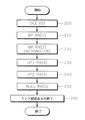
図2は、従来の1000ベース-T標準を利用する高速イーサネットでのAN方法のうち受信過程を説明するためのフローチャートである。図2を参照すれば、送信過程と同じく、受信過程でも5個のページ情報を受信した後にリンクが結成されてANが終了される。また、メッセージページは送信時と同様に同じ整数"8"を示す。
【0005】
【発明が解決しようとする課題】
図1及び図2に示されたように、現在提案されているIEEE802.3ab標準では送受信されるメッセージページを分析して1000M伝送が可能であると判断されれば、2つのUP1,UP2とNPを伝送した後にデバイスの間に正常なリンクが結成されるように決まっている。しかし、伝送デバイスの間のポート形態が相異なる場合には、UP1だけで動作モードと動作速度を決定できる。すなわち、従来はUP2が不要な場合にも、UP2が伝送されてANが完了するように具現されているので、UP2の伝送によるANのリンク結成時間が延びる問題点がある。
【0006】
本発明は上記の点に鑑みなされたもので、その目的は1000BASE-T標準で使われない特定状態のメッセージページを利用してAN機能時にリンク速度を速めうる、ギガビットイーサネットでの高速リンクのためのAN方法を提供することにある。
【0007】
さらに、本発明は、上記ギガビットイーサネットでの高速リンクを行うためのAN装置を提供することを目的とする。
【0008】
【課題を解決するための手段】
本発明に係る1000ベース-T標準を利用するギガビットイーサネットでの高速リンクのためのAN方法は、データ伝送がなされる第1伝送デバイスと第2伝送デバイスとの間にリンクを結成するためのAN方法において、(a)〜(g)段階を備える。(a)段階は、上記第1伝送デバイスと第2伝送デバイスの送信状態マシンと受信状態マシンを初期化する。(b)段階は、第1伝送デバイスと第2伝送デバイスとの間に通信能力を示すベースページを送受信する。(c)段階は、ベースページの送受信後に、第1、第2伝送デバイスに対する1000Mbps通信能力及び特定状態のメッセージ状態を示すメッセージページを送受信する。(d)段階は、動作速度、動作モード及び伝送デバイスのポート形態を示す第1UPを送受信する。(e)段階は、第1UPから伝送デバイスのM/Sを決定できるかどうかを判断する。(f)段階は、M/Sを決定できると判断されれば、第1UP後にNPを送受信する。(g)段階は、NP送受信後に上記伝送デバイス間のリンクを結成し、ANを終了する。
【0009】
本発明に係る1000ベース-T標準を利用するギガビットイーサネットでの高速リンクのためのAN装置は、データ伝送がなされる第1伝送デバイスと第2伝送デバイスとの間にリンクを結成するためのAN装置において、アービタ部、状態制御部、M/S決定部及びレジスタ部を具備する。アービタ部は第1、第2伝送デバイスに備わり、上記第1、第2伝送デバイスの間に伝送されるページ情報を利用して上記伝送デバイスをリンクさせる。状態制御部はアービタ部を通じて送信される、ANに要求されるページ情報の送信状態を制御する送信状態マシンと、相手の伝送デバイスから受信されるページ情報の受信状態を制御する受信状態マシンとを具備し、1000Mbps速度で伝送しようとする時に特定状態のメッセージページを送受信するように制御する。M/S決定部は、第1伝送デバイスと第2伝送デバイスとの間に伝送されるページ情報からM/Sを決定する。レジスタ部は、第1伝送デバイスと第2伝送デバイスとの間に送受信されるページ情報を貯蔵する。
【0010】
【発明の実施の形態】
以下、本発明に係る1000ベース-T標準を利用するギガビットイーサネットでの高速リンクのためのAN方法及びこれを行う装置に関して添付した図面を参照して次のように説明する。
【0011】
図3は、本発明の実施形態に係るギガビットイーサネットでの高速リンクのためのAN方法が適用される装置を示すものである。図3のAN装置は、イーサネットで伝送デバイスの内部に備わる物理階層チップといえ、アービタ部300、M/S決定部310、状態制御部350及びレジスタ部390を含む。
【0012】
図3に示されたAN装置を有する伝送デバイスは各パソコン(以下、PCと略称する)である場合もあり、各PCの速度によってスイッチングするハブスイッチまたはバックボーンスイッチである場合もある。
【0013】
アービタ部300は相手局の伝送デバイスとの通信速度及びモードによって回線スイッチングを仲裁する役割をする。すなわち、アービタ部300は本局の伝送デバイス及び相手局の伝送デバイスのどちらにも備わり、伝送デバイスの間に送受信されるページ情報を利用して伝送デバイスをリンクさせる。また、アービタ部300は1000Mbps速度を支援するイーサネットで伝送デバイスの間のリンクのためにAN機能を行う。
【0014】
レジスタ部390は伝送デバイスから送信するページ情報、すなわち、BP、MP、UP1、UP2などの各情報を貯蔵し、相手局の伝送デバイスから受信されるページ情報を貯蔵する。レジスタ部390はレジスタ391〜39nより構成され、上記ページ情報はレジスタ部390の該当レジスタ391〜39nに適当に貯蔵される。また、上記ページ情報は、1000Mbps速度の伝送が可能な両伝送デバイスの間のリンクのために送受信される高速リンクパルス(Fast Link Pulse: 以下、FLPという)をいう。具体的には、FLPのうちクロック信号を除外した16ビットのデータを示す。ここで、FLPは多数のノーマルリンクパルス(Normal Link Pulse: 以下、NLPという)よりなり、各デバイスの通信能力を示す。各ページ情報に関しては図4を参照して詳細に説明する。
【0015】
M/S決定部310は、伝送デバイスの動作モードがマスタの役割をするかスレーブの役割をするかを決定する。すなわち、M/S決定部310はUP1またはUP2により伝送デバイスの先順位を決定する。このような機能を行うために、M/S決定部310は第1M/Sシード320、第2M/Sシード330、M/S判断部340より構成される。第1M/Sシード320は上記UP2を通じて外部伝送デバイスに送信するランダムシード値を貯蔵する。第2M/Sシード330は相手局デバイスから受信されるランダムシード値を貯蔵する。ここで、ランダムシード値は各デバイスの間のM/Sを判断するための任意の値であって、UP2により送受信される。M/S判断部340はUP1により、またはUP2により送受信されるランダムシード値によって伝送デバイスの間のM/Sを判断する。例えば、両伝送デバイスのポート形態が同じ場合には、第1M/Sシード320に貯蔵されたランダムシード値と第2M/Sシード330に貯蔵されたランダムシード値とを比較してM/Sを決定する。また、両伝送デバイスのポート形態が相異なる場合に、M/S判断部340はUP1によりM/Sを決定する。
【0016】
状態制御部350はアービタ部300を通じて送信される、ANに要求されるページ情報の送信状態を制御する送信(TX)状態マシン360と、相手の伝送デバイスから受信されるページ情報の受信状態を制御する受信(RX)状態マシン370とを具備する。特に、状態制御部350は1000Mbps速度で伝送しようとする時に特定状態のMPを送受信するように制御する。上記ページ情報はBP、MP、UP及びNPなどである。本発明に適用される時、図3のUPはUP1とUP2を含むこともでき、UP1である場合もある。TX状態マシン360はレジスタ部390に貯蔵されたページ情報をアービタ部300を通じて相手局伝送デバイスに伝送し、以後に送信するページ情報をレジスタ部390からロードして伝送する。RX状態マシン370は外部からアービタ部300を通じて受信されるページ情報をレジスタ部390に貯蔵する。ここで、TX状態マシン360はシステム設計方式によって各レジスタにセットされた値、すなわち、該当ページ情報に関する各情報ビットを読出すだけではなく、ソフトウェア的に各レジスタにセットされる値を変えることもできる。
【0017】
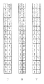
図4(a)〜図4(c)は、本発明に係るAN方法で送受信されるページ情報の構成を説明するための図であって、図4(a)はBPを、図4(b)はMPを、図4(c)はUP1、UP2を示す。
【0018】
図4(a)を参照すれば、BPは基本的な通信速度情報、例えば、10M/100M伝送を行うかどうかを示す通信能力及び1000M伝送を行えるかどうかを示す情報を含む。具体的に、図4(a)のD0〜D4に含まれたS0〜S4はセレクター領域を示し、どのプロトコルを使用するかを選択するための領域である。例えば、セレクター領域が00001と表現される時、IEEE802.3標準によるプロトコルを使用するということを示すことができる。また、A0〜A7は情報領域であってデバイスの通信能力を示す。すなわち、A0〜A7はデバイスの間に10Mまたは100Mの速度でデータを伝送することを示す。D13〜D15はページ状態領域を示す。すなわち、D13に貯蔵されるRFビットは受信側のデバイスでエラーがある場合にこれを表示するためのビットであり、ACK(Acknowledge)は受信された情報に対する承認結果を示す。また、D15のNPB(nextpagebit)は後に伝送するページ、すなわち、ネクストページ(NP;Next Page)があるかどうかを示し、1000M伝送が可能であるかどうかを判断するのに利用される。例えば、伝送するNPがあれば、1000M伝送が可能であると判断できる。
【0019】
このようなNPは1000M動作では必須の機能であり、伝送がなされる両デバイスがどちらもNP伝送機能を有する時にのみ有効である。ここで、NPは付加的な情報を伝送するためのページを示し、MPとUPの二種類がある。また、NPは1000Mで動作するイーサネットで伝送デバイスの間のM/Sを決定するために付加される。
【0020】
図4(b)を参照すれば、MPはD0〜D11に貯蔵されたM0〜M10まで11ビットのメッセージ領域と、D11〜D15のページ状態領域とにより構成される。MPはIEEE802.3abの標準で定義され、メッセージ領域には伝送デバイスが1000Mで動作できるという通信能力情報及び二つのUPが伝送されるという情報が含まれる。図4(b)のD11は該当ページ内で各ビット情報が変わる状態、すなわち、トグル状態(TOGGLE)を示し、D12とD14は受信されたメッセージに対する承認情報を示す。例えば、ACKはBPに対する承認情報を示し、ACK2はNPに対する承認情報を示す。D13のMPBは現在伝送されるページがMPであるかどうかを示すものであって、1であればMPであることを示し、0であればMPでないことを示す。D15のネクストページビット(NPB)は後に伝送されるNPがあれば1と設定され、なければ0と設定される。本発明ではMPのメッセージ領域のうち現在1EEE802.3ab標準に使われない特定状態を利用することによってUP2を伝送しなくてもリンクを結成できる。より具体的なMPの状態は図6を参照してより具体的に説明される。
【0021】
図4(c)を参照すれば、UP1、UP2の構成はD0〜D10に貯蔵されたU0〜U10の情報領域とD11〜D15のページ状態領域とにより構成される。UP1の場合に、情報領域には伝送デバイスの動作速度、動作モード、デバイス形態及び二重通信方式などが含まれる。例えば、動作速度は1000Mで動作できるかどうかを示し、動作モードはマスタの役割をするかまたはスレーブの役割をするかを示す。また、デバイス形態はマルチポートであるかシングルポートであるかを示す。二重通信方式は半二重伝送(HALF DUPLEX)であるか全二重伝送(FULL DUPLEX)であるかを示す。一方、UP2の場合に、情報領域にはランダムシード値が貯蔵される。UP1、UP2の場合に、ページ状態領域D11〜D15はMPの状態領域と同じ情報を示す。
【0022】
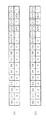
図5は、本発明に係る1000ベース-T標準を利用するイーサネットでの高速リンクのためのAN方法のうち送信過程を説明するためのフローチャートである。すなわち、図5に示された過程は、図3に示されたTX状態マシンでなされる。説明の便宜のために図3のAN装置を参照してAN方法が説明される。初期にパソコンまたはハブスイッチのような伝送デバイスに電源が供給されたり新しいリンクを決定する時、TX状態マシン360はリセットされる(第500段階)。一般に、AN機能はパソコンのブーティング時に運営体制(OPERATING SYSTEM: 以下、OSという)が行われる前に終了される。第500段階で、TX状態マシン360がリセットされればAN機能を行うために、TX状態マシン360は図4(a)のBPを送信する(第510段階、TX(1))。この時、BPのNPBが1であれば、伝送能力ABLは1000M速度で伝送できることを示す。しかし、この時、相手局伝送デバイスから受信されたBPにNPBが0と設定されていれば、TX状態マシン360は相手局の伝送能力が1000Mではない10Mまたは100Mと判断してページ伝送なしに相手局とリンクを結成する。
【0023】
前述したように、TX状態マシン360は図5(a)のBPを伝送し、相手局からNPBが1であるBPを受信すればMPを伝送する(第520段階、TX(2))。本発明ではMPのメッセージ領域M0〜M10に特定状態のメッセージを含めて伝送する。具体的な例が図6に示されている。
【0024】
図6において、図6(a)は一般のIEEE802.3ab標準で使われるMPを示し、図6(b)は本発明で使用するMPを示す。すなわち、図6(a)を参照すれば、メッセージ領域M0〜M10は整数"8"を示し、二進数で0000001000と表現されることが分かる。しかし、本発明ではIEEE802.3ab標準に使われなかった状態、すなわち、整数"16"を示すメッセージを利用する。図6(b)のメッセージ領域M0〜M10は0000010000と表現される。この時、図6(b)はMPであるので、状態領域のうちメッセージページビット(MPB)は1と設定される。以後にUP1がNPとして伝送されるので、MPのNPBは1と設定される。もし、相手局伝送デバイスから受信されたMPの状態が8を示すならば、図1に示された従来の送信過程と同一にANがなされる。
【0025】
第520段階で、16を示すMPが伝送され、16を示すMPが受信されれば、TX状態マシン360はUP1を伝送する(第530段階、TX(3))。すなわち、伝送したメッセージと同じメッセージを有するMPが受信されれば、TX状態マシン360はUP1以後にUP2が伝送されないことと判断する。この時、UP1のNPBは1と設定され、情報領域に現れる伝送能力ABLは1000M伝送が可能であることを示す。また、UP1はMPではないのでMPBは0と設定される。この時、図3のM/S判断部340は伝送されたUP1と、相手局から受信されたUP1からM/Sが決定できるかどうか判断する(第540段階)。もし、第540段階でM/Sを決定できると判断されれば、TX状態マシン360はNPを送信する(第560段階、TX(5))。ここで、UP1によりM/Sを決定できるかどうかは、UP1の情報領域に貯蔵された情報のうちデバイスのタイプによって判断できる。すなわち、データ伝送がなされる両伝送デバイスがどちらもマルチポートであるか、どちらも単一ポートである場合はUP1からM/Sを決定できない。次の表1はM/Sを決定できる基準を示す。
【0026】
【表1】

上記表1を参照すれば、伝送デバイスのうち本局のポート形態がシングルポートであり、相手局のポート形態がマルチポートであれば本局の動作モードはスレーブとなり相手局の動作モードはマスタとなる。また、本局のポート形態がシングルポートであり、相手局のポート形態がマニュアル-マスタであれば、本局はスレーブとなり相手局はマスタとなる。すなわち、マニュアル-マスタは伝送デバイスが任意にマスタの役割をするように設定しておいた状態をいう。また、マニュアル-スレーブは伝送デバイスが任意にスレーブの役割をするように設定しておいた状態をいう。表1に示されたように、相手局と本局とのポートタイプが相異なる場合には、UP1からM/Sが決定される。残りの他の場合については、表1に詳細に示されているので具体的な説明は省略される。ただし、相手局と本局とのポートタイプが同じ場合、例えば両方ともマルチポートであるか、両方ともシングルポートである場合には、UP1によりM/Sが決定されない。また、相手局と本局とのポート形態が共にマニュアル-スレーブまたはマニュアル-マスタと設定されていれば、これは構成上の欠陥(FAULT)とみなされてANがなされない。
【0028】
すなわち、UP1によりM/Sが決定されれば、M/S判断部340は判断結果をTX状態マシン360とRX状態マシン370とに伝送して次に伝送するページはUP2ではないNPであることを知らせる。したがって、TX状態マシン360はUP1を伝送した後にUP2を伝送せずに、NPを伝送する(第560段階、TX(5))。NPの場合に、それ以上伝送されるNPはないのでNPBは0と設定される。また、NPの具体的な構成が示されなかったが、NPはMPであるため、MPBは1と設定される。このような過程を経てリンクが結成され、ANが終了する(第570段階)。
【0029】
一方、第540段階で、UP1からM/Sが決定されなければ、TX状態マシン360はUP1以後にUP2を伝送する(第550段階)。この時、送信されるUP2のランダムシード値は第1M/Sシード320に貯蔵される。また、相手局からUP2により受信されるランダムシード値は第2M/Sシード330に貯蔵される。したがって、M/S判断部340は第1M/Sシード320に貯蔵されたランダムシード値と、第2M/Sシード330に貯蔵されたランダムシード値とを比較してより大きい値を有するデバイスがマスタになるように決定する。したがって、小さなランダムシード値を有するデバイスはスレーブの役割をする。UP2で、以後に伝送するNPがあるので、NPBは1と設定され、ページの能力ABLはランダムシード値により判断されるので、"RANDOM"と設定される。また、UP2もMPではないのでMPBは0と設定される。TX状態マシン360はUP2後にNPを伝送し(第560段階)、相手局からNPを受信すればリンクを結成してANを終了する(第570段階)。
【0030】
また、第520段階で16を示すMPを相手局に送信した後、相手局から8を示すMPを受信すれば、TX状態マシン360はUP1とUP2を正常に送信してANを行う。
【0031】
図7は、本発明に係る1000ベース-T標準を利用するイーサネットでの高速リンクのためのAN方法のうち受信過程を説明するためのフローチャートであって、図3のRX状態マシン370で行われる。初期にRX状態マシン370はアイドル状態にある(第700段階)。図7の受信過程も送信過程と連繋してなされるので、大部分類似の過程でなされる。すなわち、RX状態マシン370は相手局からBPを受信し(第710段階、RX(1))、以後に16の状態を示すMPを受信する(第720段階、RX(2))。第720段階で16のメッセージを有するMPを受信すれば、RX状態マシン370はUP2が受信されないことを認識する。第720段階後に、RX状態マシン370はUP1を受信する(第730段階、RX(3))。また、第730段階後にUP1からM/Sが決定されるかどうかが判断される(第740段階)。第740段階で、M/Sを決定できるならば、RX状態マシン370は次に受信されるページがNPであると判断して(第760段階、RX(5))リンクを結成する(第770段階)。また、第740段階でUP1からM/Sが決定されなければ、正常にUP2を受信し(第750段階、RX(4))、以後にNPを受信する(第760段階)。以後にリンクが結成されてANが終了する(第770段階)。
【0032】
図5及び図7で説明されたように、本発明では特定状態のMPを使用することによって、AN時にUP2を伝送するのにかかる時間TX(4)、RX(4)だけ短くすることができる。
【0033】
以上、最適な実施形態が開示された。ここで特定の用語が使われたが、これは単に本発明を説明するための目的で使われたものであって、意味限定や特許請求の範囲に記載された本発明の範囲を制限するために使われたものではない。したがって本技術分野の通常の知識を有する者であればこれより多様な変形及び均等な他の実施形態が可能である点を理解できる。したがって、本発明の真の技術的保護範囲は特許請求の範囲の技術的思想により決まらねばならない。
【0034】
【発明の効果】
以上のように本発明によれば、ギガビットイーサネットでAN機能の遂行時、IEEE802.3ab標準で使用しない特定状態、すなわち、16のメッセージを有するMPを送受信することによってUP2を伝送するのにかかる時間TX(4)、RX(4)だけ短くすることができる。したがって、AN遂行時に各ページ伝送に要求される全体時間の1/5を縮められるのでリンク結成速度が速くなるという効果がある。
【図面の簡単な説明】
【図1】従来の1000ベース-T標準を利用する高速イーサネットでのAN方法のうち送信過程を説明するためのフローチャートである。
【図2】従来の1000ベース-T標準を利用する高速イーサネットでのAN方法のうち受信過程を説明するためのフローチャートである。
【図3】本発明に係る1000ベース-T標準を利用する高速イーサネットでのAN方法を行うための装置を示す図である。
【図4】図4(a)ないし図4(c)は、図3に示された装置でAN機能のために送受信されるページ情報を説明するための図である。
【図5】本発明の実施形態に係る1000ベース-T標準を利用する高速イーサネットでのAN方法のうち送信過程を説明するためのフローチャートである。
【図6】図6(a)及び図6(b)は、ANがなされる時に伝送されるMPを説明するための図である。
【図7】本発明の実施形態に係る1000ベース-T標準を利用する高速イーサネットでのAN方法のうち受信過程を説明するためのフローチャートである。
【符号の説明】
300 アービタ部
310 M/S決定部
350 状態制御部
390 レジスタ部[0001]
BACKGROUND OF THE INVENTION
The present invention relates to high-speed Ethernet, and more particularly, to an auto-negotiation method and auto-negotiation apparatus for high-speed links in Gigabit Ethernet using the 1000 Base-T standard.
[0002]
[Prior art]
In general, Ethernet is a network model used for a local area network (LAN) of an information communication network provided in a specific area, and is a coaxial cable network adopted by the Institute of Electrical and Electronic Engineers (IEEE). Currently, Gigabit Ethernet is widely used as the speed of Ethernet increases. Gigabit Ethernet is defined in IEEE 802.3, and in particular, the 1000Base-T standard is one of standard protocols using coaxial cables, and defines the IEEE 802.3ab specification. Among the functions of Gigabit Ethernet, an auto-negotiation (hereinafter referred to as AN) function is indispensably added for the transmission device, that is, the link between the remote station (remote) and the main station (local). Used. In other words, the AN function refers to a function that determines the communication speed and operation mode between the partner station and the head station before the link is formed between the partner station and the head station, and performs communication based on this. With Gigabit Ethernet, that is, 10/100 Mbps Ethernet that is not 1000 Mbps, the communication speed and mode can be determined by the parallel detection function even if the main station does not have an AN function. Here, the parallel detection function means that when a device that does not use the AN function and a device that uses the AN function are connected to each other, the device that does not use the AN function senses that it is in normal transmission mode and is in normal mode. A function that is automatically converted to. However, in the case of Ethernet at 1000 Mbps speed, the communication speed and mode between transmission devices must be determined by the AN function. In addition, in the Gigabit Ethernet, a master / slave (Master / Slave: hereinafter abbreviated as M / S) function is added. That is, since one of the devices connected to each other must perform the role of a master and the other one must perform the role of a slave, the AN function is essential.
[0003]
FIG. 1 is a flowchart for explaining a transmission process in an AN method in a high-speed Ethernet using a conventional 1000 base-T standard. Referring to FIG. 1, in order to perform an AN function according to the 1000 Base-T standard, five page transmission stages have to be performed between transmission devices. Specifically, the transmission device transmits a base page (hereinafter referred to as BP) indicating a communication standard and a basic communication speed after an initial reset (step 100) (step 110). A message page (Message Page: hereinafter referred to as MP) that informs that 1000 Mbps transmission is possible after step 110 and that two unformatted messages (hereinafter referred to as UP) will be transmitted later. Is transmitted (step 120). At this time, the message expressed in MP generally indicates a predetermined number, for example, “8”. That is, the message “8” indicates that two UPs will be transmitted thereafter. Thereafter, the transmission device transmits UP1 and UP2 (
[0004]
FIG. 2 is a flowchart for explaining a reception process in the AN method in the high-speed Ethernet using the conventional 1000 base-T standard. Referring to FIG. 2, in the same manner as in the transmission process, after receiving 5 pieces of page information, a link is formed and the AN is terminated. The message page indicates the same integer “8” as in the transmission.
[0005]
[Problems to be solved by the invention]
As shown in FIG. 1 and FIG. 2, if the currently proposed IEEE 802.3ab standard analyzes message pages sent and received and determines that 1000M transmission is possible, two UP1, UP2 and NP It is determined that a normal link is formed between the devices after transmitting. However, when the port configuration between the transmission devices is different, the operation mode and the operation speed can be determined only by UP1. In other words, conventionally, even when UP2 is not required, it is implemented so that UP2 is transmitted and the AN is completed.
[0006]
The present invention has been made in view of the above points. The purpose of the present invention is to provide a high-speed link in Gigabit Ethernet that can increase the link speed during AN function using a message page in a specific state that is not used in the 1000BASE-T standard. Is to provide an AN method.
[0007]
Furthermore, an object of the present invention is to provide an AN apparatus for performing a high-speed link in the Gigabit Ethernet.
[0008]
[Means for Solving the Problems]
An AN method for a high-speed link in Gigabit Ethernet using the 1000 Base-T standard according to the present invention is an AN for forming a link between a first transmission device and a second transmission device through which data is transmitted. The method comprises steps (a) to (g). The step (a) initializes a transmission state machine and a reception state machine of the first transmission device and the second transmission device. In step (b), a base page indicating communication capability is transmitted and received between the first transmission device and the second transmission device. In step (c), after transmitting / receiving the base page, a message page indicating 1000 Mbps communication capability for the first and second transmission devices and a message state in a specific state is transmitted / received. In step (d), the first UP indicating the operation speed, the operation mode, and the port configuration of the transmission device is transmitted and received. In step (e), it is determined whether the M / S of the transmission device can be determined from the first UP. In step (f), if it is determined that M / S can be determined, NP is transmitted / received after the first UP. In step (g), a link is established between the transmission devices after NP transmission / reception, and the AN is terminated.
[0009]
An AN apparatus for high-speed link in Gigabit Ethernet using the 1000 Base-T standard according to the present invention is an AN for forming a link between a first transmission device and a second transmission device through which data is transmitted. The apparatus includes an arbiter unit, a state control unit, an M / S determination unit, and a register unit. The arbiter unit is provided in the first and second transmission devices, and links the transmission devices using page information transmitted between the first and second transmission devices. The state control unit includes a transmission state machine that controls the transmission state of the page information requested by the AN transmitted through the arbiter unit, and a reception state machine that controls the reception state of the page information received from the other transmission device. And control to transmit / receive a message page in a specific state when transmitting at a speed of 1000 Mbps. The M / S determination unit determines the M / S from page information transmitted between the first transmission device and the second transmission device. The register unit stores page information transmitted and received between the first transmission device and the second transmission device.
[0010]
DETAILED DESCRIPTION OF THE INVENTION
Hereinafter, an AN method for a high-speed link in Gigabit Ethernet using the 1000 Base-T standard according to the present invention and an apparatus for performing the same will be described with reference to the accompanying drawings.
[0011]
FIG. 3 shows an apparatus to which an AN method for high-speed links in Gigabit Ethernet according to an embodiment of the present invention is applied. The AN apparatus of FIG. 3 is a physical layer chip provided inside the transmission device using Ethernet, and includes an
[0012]
The transmission device having the AN apparatus shown in FIG. 3 may be each personal computer (hereinafter abbreviated as “PC”), or may be a hub switch or a backbone switch that switches according to the speed of each PC.
[0013]
The
[0014]
The
[0015]
The M /
[0016]
The
[0017]
4 (a) to 4 (c) are diagrams for explaining the configuration of page information transmitted and received by the AN method according to the present invention. FIG. 4 (a) shows BP, FIG. ) Shows MP, and FIG. 4C shows UP1 and UP2.
[0018]
Referring to FIG. 4A, the BP includes basic communication speed information, for example, communication capability indicating whether or not 10M / 100M transmission is performed and information indicating whether or not 1000M transmission can be performed. Specifically, S0 to S4 included in D0 to D4 in FIG. 4A indicate selector areas, which are areas for selecting which protocol to use. For example, when the selector area is expressed as 00001, it can indicate that the protocol according to the IEEE 802.3 standard is used. A0 to A7 are information areas indicating the communication capability of the device. That is, A0 to A7 indicate that data is transmitted between devices at a speed of 10M or 100M. D13 to D15 indicate page state areas. That is, the RF bit stored in D13 is a bit for displaying an error in the receiving device, and ACK (Acknowledge) indicates an acknowledgment result for the received information. The NPB (next page bit) of D15 indicates whether there is a page to be transmitted later, that is, whether there is a next page (NP; Next Page), and is used to determine whether 1000M transmission is possible. For example, if there is an NP to be transmitted, it can be determined that 1000M transmission is possible.
[0019]
Such NP is an indispensable function in 1000M operation, and is effective only when both devices that perform transmission have an NP transmission function. Here, NP indicates a page for transmitting additional information, and there are two types, MP and UP. The NP is added to determine the M / S between transmission devices in Ethernet operating at 1000M.
[0020]
Referring to FIG. 4B, the MP is composed of a message area of 11 bits from M0 to M10 stored in D0 to D11, and a page status area of D11 to D15. The MP is defined by the IEEE 802.3ab standard, and the message area includes communication capability information indicating that the transmission device can operate at 1000M and information indicating that two UPs are transmitted. In FIG. 4B, D11 indicates a state where each bit information is changed in the corresponding page, that is, a toggle state (TOGGLE), and D12 and D14 indicate acknowledgment information for the received message. For example, ACK indicates approval information for BP, and ACK2 indicates approval information for NP. The MPB of D13 indicates whether the currently transmitted page is MP. If it is 1, it indicates that it is MP, and if it is 0, it indicates that it is not MP. The next page bit (NPB) of D15 is set to 1 if there is an NP transmitted later, and is set to 0 if there is no NP transmitted later. In the present invention, a link can be formed without transmitting UP2 by using a specific state that is not currently used in the 1EEE802.3ab standard in the message area of MP. A more specific state of the MP will be described more specifically with reference to FIG.
[0021]
Referring to FIG. 4C, the configurations of UP1 and UP2 are configured by the information areas U0 to U10 stored in D0 to D10 and the page status areas D11 to D15. In the case of UP1, the information area includes an operation speed, an operation mode, a device form, a duplex communication method, and the like of the transmission device. For example, the operation speed indicates whether it can operate at 1000M, and the operation mode indicates whether to act as a master or a slave. Further, the device type indicates whether it is multi-port or single port. The duplex communication system indicates half-duplex transmission (HALF DUPLEX) or full-duplex transmission (FULL DUPLEX). On the other hand, in the case of UP2, a random seed value is stored in the information area. In the case of UP1 and UP2, the page status areas D11 to D15 indicate the same information as the MP status area.
[0022]
FIG. 5 is a flowchart for explaining a transmission process in an AN method for high-speed link in Ethernet using the 1000 base-T standard according to the present invention. That is, the process shown in FIG. 5 is performed by the TX state machine shown in FIG. For convenience of explanation, the AN method will be described with reference to the AN apparatus of FIG. Initially, when a transmission device such as a personal computer or a hub switch is powered on or determines a new link, the
[0023]
As described above, the
[0024]
6A shows an MP used in the general IEEE 802.3ab standard, and FIG. 6B shows an MP used in the present invention. That is, referring to FIG. 6A, it can be seen that the message areas M0 to M10 indicate the integer “8” and are expressed as binary numbers 0000001000. However, in the present invention, a message that is not used in the IEEE 802.3ab standard, that is, a message indicating the integer “16” is used. The message areas M0 to M10 in FIG. 6B are expressed as 000001000. At this time, since FIG. 6B is MP, the message page bit (MPB) in the status area is set to 1. Thereafter, UP1 is transmitted as NP, so that NPB of MP is set to 1. If the MP status received from the counterpart station transmission device indicates 8, AN is performed in the same manner as the conventional transmission process shown in FIG.
[0025]
In
[0026]
[Table 1]
Referring to Table 1 above, if the port form of the main station is a single port among the transmission devices and the port form of the counterpart station is multi-port, the operation mode of the master station is slave and the operation mode of the counterpart station is master. If the port type of the main station is a single port and the port type of the partner station is manual-master, the master station becomes a slave and the partner station becomes a master. That is, the manual-master is a state in which the transmission device is set to arbitrarily act as a master. Manual-slave is a state in which the transmission device is set to arbitrarily function as a slave. As shown in Table 1, when the port types of the partner station and the main station are different, M / S is determined from UP1. The remaining other cases are shown in detail in Table 1 and will not be described in detail. However, if the port types of the partner station and the main station are the same, for example, if both are multi-ports or both are single ports, M / S is not determined by UP1. If both the partner station and the main station are set to manual-slave or manual-master, this is regarded as a structural defect (FAULT) and no AN is made.
[0028]
That is, if M / S is determined by UP1, the M /
[0029]
On the other hand, if M / S is not determined from UP1 in
[0030]
Also, after transmitting MP indicating 16 to the partner station in
[0031]
FIG. 7 is a flowchart for explaining a reception process in the AN method for high-speed link over Ethernet using the 1000 base-T standard according to the present invention, which is performed by the
[0032]
As described with reference to FIGS. 5 and 7, in the present invention, by using the MP in a specific state, it is possible to shorten the times TX (4) and RX (4) required to transmit UP2 during AN. .
[0033]
Thus, the optimal embodiment has been disclosed. Although specific terms are used herein, they are used merely for purposes of describing the present invention and are intended to limit the scope of the invention as defined in the meaning and claims. It was not used for Accordingly, those skilled in the art can understand that various modifications and other equivalent embodiments are possible. Therefore, the true technical protection scope of the present invention must be determined by the technical idea of the scope of claims.
[0034]
【The invention's effect】
As described above, according to the present invention, when performing an AN function in Gigabit Ethernet, a specific state not used in the IEEE 802.3ab standard, that is, a time taken to transmit UP2 by transmitting / receiving an MP having 16 messages. TX (4) and RX (4) can be shortened. Therefore, 1/5 of the total time required for transmission of each page can be shortened at the time of performing AN, so that the link formation speed is increased.
[Brief description of the drawings]
FIG. 1 is a flowchart for explaining a transmission process in an AN method in a high-speed Ethernet using a conventional 1000 base-T standard.
FIG. 2 is a flowchart for explaining a reception process in an AN method in a high-speed Ethernet using a conventional 1000 base-T standard.
FIG. 3 is a diagram illustrating an apparatus for performing an AN method in high-speed Ethernet using the 1000 Base-T standard according to the present invention.
4 (a) to 4 (c) are diagrams for explaining page information transmitted and received for the AN function in the apparatus shown in FIG.
FIG. 5 is a flowchart for explaining a transmission process in an AN method in high-speed Ethernet using the 1000 base-T standard according to an embodiment of the present invention.
FIGS. 6A and 6B are diagrams for explaining an MP transmitted when AN is performed. FIGS.
FIG. 7 is a flowchart for explaining a reception process in the AN method in the high-speed Ethernet using the 1000 base-T standard according to the embodiment of the present invention.
[Explanation of symbols]
300 Arbiter unit 310 M /
Claims (20)
(a) 上記第1伝送デバイスと第2伝送デバイスの送信状態マシンと受信状態マシンを初期化する段階と、
(b) 上記送信及び受信状態マシンが初期化されれば、上記第1伝送デバイスと上記第2伝送デバイスとの間に通信能力を示すベースページを送受信する段階と、
(c) 上記ベースページの送受信後に、上記第1、第2伝送デバイスに対する1000Mbps通信能力及び特定状態のメッセージ状態を示すメッセージページを送受信する段階と、
(d) 上記メッセージページ送受信後に、動作速度、動作モード及び上記伝送デバイスのポート形態を示す第1非形式ページを送受信する段階と、
(e) 上記送受信された上記第1非形式ページから上記伝送デバイスのマスタ/スレーブを決定できるかどうかを判断する段階と、
(f) 上記(e)段階で上記マスタ/スレーブを決定できると判断されれば、上記第1非形式ページ後にヌルページを送受信する段階と、
(g) 上記ヌルページ送受信後に上記伝送デバイス間のリンクを結成し、自動-交渉(AN)を終了する段階とを具備することを特徴とする高速リンクのための自動-交渉方法。In an auto-negotiation method for establishing a link between a first transmission device and a second transmission device for data transmission,
(a) initializing a transmission state machine and a reception state machine of the first transmission device and the second transmission device;
(b) if the transmission and reception state machine is initialized, transmitting and receiving a base page indicating communication capability between the first transmission device and the second transmission device;
(c) after transmitting / receiving the base page, transmitting / receiving a message page indicating a 1000 Mbps communication capability and a specific message state for the first and second transmission devices;
(d) transmitting / receiving a first unformatted page indicating an operation speed, an operation mode, and a port form of the transmission device after transmitting / receiving the message page;
(e) determining whether the master / slave of the transmission device can be determined from the transmitted / received first informal page;
(f) If it is determined in step (e) that the master / slave can be determined, a step of transmitting / receiving a null page after the first informal page;
(g) forming a link between the transmission devices after transmitting / receiving the null page, and ending auto-negotiation (AN); and an auto-negotiation method for a high-speed link.
上記特定状態のメッセージページは整数"16"を示すメッセージを含むことを特徴とする請求項1に記載の高速リンクのための自動-交渉方法。In step (c) above,
The auto-negotiation method for a high speed link according to claim 1, wherein the message page in the specific state includes a message indicating an integer "16".
(c1) 上記伝送デバイスのうちいずれか一つの伝送デバイスから上記1000Mbpsの通信能力及び上記特定状態のメッセージページを送信した後、上記他の一つの伝送デバイスから上記同じ特定状態のメッセージページを受信するかどうかを判断する段階と、
(c2) 上記(c1)段階で同じ特定状態のメッセージページを受信すると判断されれば、上記(d)〜(g)段階を行う段階とを含むことを特徴とする請求項1に記載の高速リンクのための自動-交渉方法。Step (c) above
(c1) After transmitting the 1000 Mbps communication capability and the message page in the specific state from any one of the transmission devices, the message page in the same specific state is received from the other transmission device. The stage of determining whether or not
(c2) The method according to claim 1, further comprising the steps of (d) to (g) when it is determined that the message page having the same specific state is received in the step (c1). Auto-negotiation method for links.
上記第1、第2伝送デバイスのポート形態が相異なるかどうかを判断して相異なれば、上記マスタ/スレーブを決定できると判断することを特徴とする請求項1に記載の高速リンクのための自動-交渉方法。Step (e) above
The high-speed link for the high-speed link according to claim 1, wherein the master / slave can be determined if the port configurations of the first and second transmission devices are different from each other. Auto-negotiation method.
(i) 上記(h)段階後に上記ヌルページを送受信してリンクを結成し、上記自動-交渉を終了する段階とをさらに具備し、
上記第2非形式ページはランダムシード値を含むことを特徴とする請求項1に記載の高速リンクのための自動-交渉方法。(h) If it is determined in step (e) that the master / slave cannot be determined, the first and second transmission devices transmit and receive a second informal page after transmitting and receiving the first informal page;
(i) further comprising the step of transmitting and receiving the null page after the step (h) to form a link and terminating the auto-negotiation,
The method of claim 1, wherein the second informal page includes a random seed value.
上記第1、第2伝送デバイスに備わり、上記第1、第2伝送デバイスの間に伝送されるページ情報を利用して上記伝送デバイスをリンクさせるアービタ部と、
このアービタ部を通じて送信される、自動-交渉に要求されるページ情報の送信状態を制御する送信状態マシンと、相手の伝送デバイスから受信される上記ページ情報の受信状態を制御する受信状態マシンとを具備し、1000Mbps速度で伝送しようとする時に特定状態のメッセージページを送受信するように制御する状態制御部と、
上記第1伝送デバイスと上記第2伝送デバイスとの間に伝送される上記ページ情報からマスタ/スレーブを決定するM/S決定部と、
上記第1伝送デバイスと上記第2伝送デバイスとの間に送受信される上記ページ情報を貯蔵するためのレジスタ部とを具備し、
上記ページ情報は、
ベースページ、メッセージページ、第1非形式ページ、前記第1非形式ページから前記マスタ/スレーブが決定されない場合は第2非形式ページ、及びヌルページのうち少なくとも一つであることを特徴とする高速リンクのための自動-交渉装置。In an auto-negotiation device for establishing a link between a first transmission device and a second transmission device through which data is transmitted,
An arbiter unit that is provided in the first and second transmission devices and links the transmission devices using page information transmitted between the first and second transmission devices;
A transmission state machine that controls the transmission state of the page information required for auto-negotiation transmitted through the arbiter unit, and a reception state machine that controls the reception state of the page information received from the other transmission device. A state control unit that controls to transmit and receive a message page in a specific state when attempting to transmit at a speed of 1000 Mbps,
An M / S determination unit for determining a master / slave from the page information transmitted between the first transmission device and the second transmission device;
A register unit for storing the page information transmitted and received between the first transmission device and the second transmission device;
The page information above is
A high speed characterized by being at least one of a base page, a message page, a first unformatted page, a second unformatted page when the master / slave is not determined from the first unformatted page , and a null page. Auto-negotiation device for link.
上記第1、第2伝送デバイスの間のデータ伝送速度を1000Mbpsとして伝送する時、整数“16”を示す上記特定メッセージページを送受信するように制御することを特徴とする請求項8に記載の高速リンクのための自動-交渉装置。The send / receive state machine is
9. The high speed according to claim 8, wherein when the data transmission rate between the first and second transmission devices is transmitted at 1000 Mbps, the specific message page indicating the integer "16" is controlled to be transmitted and received. Auto-negotiation device for link.
上記特定メッセージページを送受信した後に上記第1非形式ページと上記ヌルページを送受信することを特徴とする請求項9に記載の高速リンクのための自動-交渉装置。The send / receive state machine is
10. The auto-negotiation apparatus for a high speed link according to claim 9, wherein the first informal page and the null page are transmitted / received after transmitting / receiving the specific message page.
上記第1または第2伝送デバイスから受信された上記メッセージページが16以外の他の値を示す時、上記第1非形式ページ、上記第2非形式ページ及び上記ヌルページを順次に送受信するように制御することを特徴とする請求項9に記載の高速リンクのための自動-交渉装置。The send / receive state machine is
When the message page received from the first or second transmission device indicates a value other than 16, the first unformatted page, the second unformatted page, and the null page are sequentially transmitted and received. 10. The auto-negotiation device for high-speed links according to claim 9, characterized by controlling.
パソコン、ハブスイッチ及びバックボーンスイッチのうちいずれか一つであることを特徴とする請求項8に記載の高速リンクのための自動-交渉装置。The first and second transmission devices are
9. The auto-negotiation device for a high-speed link according to claim 8, wherein the auto-negotiation device is one of a personal computer, a hub switch, and a backbone switch.
(a) 上記第1伝送デバイスと第2伝送デバイスとの間に通信能力を示すベースページを送受信する段階と、
(b) 上記ベースページ送受信後に、上記第1及び第2伝送デバイスに対するあらかじめ決まった通信能力及び特定状態のメッセージ状態を示すメッセージページを送受信する段階と、
(c) 上記メッセージページ送受信後に、第1及び第2伝送デバイスに関する伝送情報を示す第1非形式ページを送受信する段階と、
(d) 上記第1非形式ページによって第1及び第2伝送デバイスのマスタ/スレーブが決定されると判断されれば、第1非形式ページ後にヌルページを送受信する段階と、
(e) 上記ヌルページ送受信後に、上記第1及び第2伝送デバイスの間に高速リンクを結成して自動-交渉(AN)を終了する段階とを具備することを特徴とする高速リンクのための自動-交渉方法。In an auto-negotiation method for forming a high-speed link between a first transmission device and a second transmission device for data transmission,
(a) transmitting and receiving a base page indicating communication capability between the first transmission device and the second transmission device;
(b) after transmitting and receiving the base page, transmitting and receiving a message page indicating a predetermined communication capability and a specific message state for the first and second transmission devices;
(c) after transmitting / receiving the message page, transmitting / receiving a first unformatted page indicating transmission information regarding the first and second transmission devices;
(d) if it is determined that the master / slave of the first and second transmission devices is determined by the first informal page, transmitting and receiving a null page after the first informal page;
(e) after transmitting and receiving the null page, forming a high speed link between the first and second transmission devices and terminating auto-negotiation (AN). Auto-negotiation method.
上記特定状態のメッセージページは整数“16”を示すことを特徴とする請求項13に記載の高速リンクのための自動-交渉方法。In step (b) above,
14. The auto-negotiation method for a high-speed link according to claim 13, wherein the message page in the specific state indicates an integer "16".
(b1) 上記第1及び第2伝送デバイスのうちいずれか一つから上記メッセージページを送信する段階と、
(b2) 上記第1及び第2伝送デバイスのうち他の一つから上記メッセージページを受信するかどうかを決定する段階と、
(b3) 上記メッセージページを受信すると決定されれば上記(c)〜(e)段階を行う段階とを具備することを特徴とする請求項13に記載の高速リンクのための自動-交渉方法。Step (b) above
(b1) transmitting the message page from any one of the first and second transmission devices;
(b2) determining whether to receive the message page from another one of the first and second transmission devices;
14. The auto-negotiation method for a high speed link according to claim 13, further comprising: (b3) performing the steps (c) to (e) if it is determined that the message page is received.
上記第1及び第2伝送デバイスが他のポートタイプを有する時、上記マスタ/スレーブが決定されることを特徴とする請求項13に記載の高速リンクのための自動-交渉方法。In stage (d) above,
The method of claim 13, wherein the master / slave is determined when the first and second transmission devices have other port types.
(g) 上記(f)段階後に上記ヌルページを送受信してリンクを結成し、上記自動-交渉を終了する段階とをさらに具備し、
上記第2非形式ページはランダムシード値を含むことを特徴とする請求項13に記載の高速リンクのための自動-交渉方法。(f) If it is determined in the step (d) that the master / slave cannot be determined, the first and second transmission devices transmit and receive a second unformatted page after transmitting and receiving the first unformatted page;
(g) after the step (f), further comprising the step of transmitting and receiving the null page to form a link and terminating the auto-negotiation,
The method of claim 13, wherein the second non-formal page includes a random seed value.
上記あらかじめ決まった通信能力は1000Mbpsであることを特徴とする請求項13に記載の高速リンクのための自動-交渉方法。In step (b) above,
14. The auto-negotiation method for a high speed link according to claim 13, wherein the predetermined communication capability is 1000 Mbps.
Applications Claiming Priority (2)
| Application Number | Priority Date | Filing Date | Title |
|---|---|---|---|
| KR2001-002169 | 2001-01-15 | ||
| KR10-2001-0002169A KR100389922B1 (en) | 2001-01-15 | 2001-01-15 | Auto-negotiation method for high speed link in gigabit ethernet using 1000base-t standard and apparatus thereof |
Publications (2)
| Publication Number | Publication Date |
|---|---|
| JP2002271445A JP2002271445A (en) | 2002-09-20 |
| JP3913552B2 true JP3913552B2 (en) | 2007-05-09 |
Family
ID=19704638
Family Applications (1)
| Application Number | Title | Priority Date | Filing Date |
|---|---|---|---|
| JP2002006515A Expired - Fee Related JP3913552B2 (en) | 2001-01-15 | 2002-01-15 | Auto-negotiation method and auto-negotiation device for high-speed links |
Country Status (4)
| Country | Link |
|---|---|
| US (1) | US7054947B2 (en) |
| JP (1) | JP3913552B2 (en) |
| KR (1) | KR100389922B1 (en) |
| TW (1) | TWI223523B (en) |
Families Citing this family (30)
| Publication number | Priority date | Publication date | Assignee | Title |
|---|---|---|---|---|
| US6703947B1 (en) | 2000-09-22 | 2004-03-09 | Tierravision, Inc. | Method for organizing and compressing spatial data |
| US7301959B1 (en) * | 2003-02-24 | 2007-11-27 | United States Of America As Represented By The Secretary Of The Navy | System and method for multiplying communications capacity on a time domain multiple access network using slave channeling |
| US8019887B2 (en) * | 2003-09-04 | 2011-09-13 | Intel Corporation | Method, system, and program for managing a speed at which data is transmitted between network adaptors |
| US20050157646A1 (en) * | 2004-01-16 | 2005-07-21 | Nokia Corporation | System and method of network congestion control by UDP source throttling |
| JP4541013B2 (en) | 2004-03-29 | 2010-09-08 | 富士通株式会社 | Network equipment with Ethernet interface |
| US7245258B2 (en) * | 2004-06-25 | 2007-07-17 | Intel Corporation | Location processing apparatus, systems, and methods |
| US20060058953A1 (en) | 2004-09-07 | 2006-03-16 | Cooper Clive W | System and method of wireless downloads of map and geographic based data to portable computing devices |
| US7135996B1 (en) * | 2004-11-04 | 2006-11-14 | Marvell International Ltd. | Multispeed communications device |
| US7352283B2 (en) * | 2004-12-08 | 2008-04-01 | Intel Corporation | Computing platform security apparatus, systems, and methods |
| US7757020B2 (en) * | 2005-06-29 | 2010-07-13 | Intel Corporation | Point-to-point link negotiation method and apparatus |
| US20070192505A1 (en) * | 2006-02-13 | 2007-08-16 | Teranetics, Inc. | Auto-sequencing transmission speed of a data port |
| TWI350673B (en) * | 2006-03-07 | 2011-10-11 | Realtek Semiconductor Corp | Method for determining connection status of wired network |
| TWI444021B (en) * | 2007-09-17 | 2014-07-01 | Htc Corp | Method for decrypting serial transmission signal |
| US20090201821A1 (en) * | 2008-02-11 | 2009-08-13 | Barnette James D | System and method for detecting early link failure in an ethernet network |
| US8019895B2 (en) | 2008-03-25 | 2011-09-13 | International Business Machines Corporation | Serial attached SCSI and serial ATA wide port tunnelling through a fibre channel connection |
| US7809865B2 (en) * | 2008-04-25 | 2010-10-05 | International Business Machines Corporation | Apparatus and method to set a communication speed for a SAS/SATA distance extender |
| US20100142418A1 (en) * | 2008-06-02 | 2010-06-10 | Shinichiro Nishioka | Data communication system, data communication request device, and data communication response device |
| CN101785282B (en) * | 2008-06-20 | 2014-07-02 | 松下电器产业株式会社 | Data communication system, communication device, and communication method |
| US8693379B2 (en) | 2008-07-22 | 2014-04-08 | Panasonic Corporation | Communication system, communication device, and communication method |
| CN101494560B (en) * | 2009-02-20 | 2011-11-09 | 华为技术有限公司 | Method, apparatus and system for configuring master-salve network device |
| WO2011145154A1 (en) * | 2010-05-18 | 2011-11-24 | パナソニック株式会社 | Communication apparatus, television receiver, image signal processing apparatus, communication method, program, and integrated circuit |
| US20130132500A1 (en) * | 2011-11-18 | 2013-05-23 | Apple Inc. | Selection of a master in a peer-to-peer network environment |
| US10271293B2 (en) | 2011-11-18 | 2019-04-23 | Apple Inc. | Group formation within a synchronized hierarchy of peer-to-peer devices |
| US9516615B2 (en) | 2011-11-18 | 2016-12-06 | Apple Inc. | Selection of synchronization stations in a peer-to-peer network environment |
| JP5576421B2 (en) * | 2012-03-21 | 2014-08-20 | Necアクセステクニカ株式会社 | COMMUNICATION DEVICE, COMMUNICATION METHOD, AND PROGRAM |
| TWI492576B (en) | 2013-03-11 | 2015-07-11 | Realtek Semiconductor Corp | Master-slave detection method and master-slave detection circuit |
| US9544091B2 (en) * | 2014-05-09 | 2017-01-10 | Broadcom Corporation | Bandwidth control for differential manchester encoding auto-negotiation signaling |
| WO2016120976A1 (en) * | 2015-01-26 | 2016-08-04 | 三菱電機株式会社 | Communication device and method |
| KR102446092B1 (en) * | 2016-02-26 | 2022-09-21 | 현대자동차주식회사 | How to diagnose link status in the network |
| KR102471004B1 (en) | 2017-12-13 | 2022-11-25 | 현대자동차주식회사 | In-vehicle Ethernet communication system and communication method thereof |
Family Cites Families (14)
| Publication number | Priority date | Publication date | Assignee | Title |
|---|---|---|---|---|
| US5883894A (en) * | 1996-12-30 | 1999-03-16 | 3Com Corporation | Shared auto-negotiation logic for multiple port network devices |
| EP0863640A3 (en) * | 1997-03-04 | 2005-09-21 | Texas Instruments Incorporated | Improved physical layer interface device |
| US6198727B1 (en) * | 1997-03-31 | 2001-03-06 | Hewlett-Packard Company | Method and apparatus for providing 10Base-T/100Base-TX link assurance |
| US6169729B1 (en) * | 1997-04-08 | 2001-01-02 | Level One Communications, Inc. | 200 Mbps PHY/MAC apparatus and method |
| US5991303A (en) * | 1997-07-28 | 1999-11-23 | Conexant Systems, Inc. | Multi-rate switching physical device for a mixed communication rate ethernet repeater |
| KR100236082B1 (en) * | 1997-11-29 | 1999-12-15 | 김영환 | Ethernet lan adapting driver and method for enhancing the delayed loading time |
| US6115389A (en) * | 1998-04-17 | 2000-09-05 | Advanced Micro Devices, Inc. | Auto-negotiation for multiple ports using shared logic |
| US6269104B1 (en) * | 1998-04-21 | 2001-07-31 | Hewlett- Packard Company | Link control state machine for controlling a media access controller, a serial physical layer device and a media independent interface physical layer device |
| US6477200B1 (en) * | 1998-11-09 | 2002-11-05 | Broadcom Corporation | Multi-pair gigabit ethernet transceiver |
| US6631520B1 (en) * | 1999-05-14 | 2003-10-07 | Xilinx, Inc. | Method and apparatus for changing execution code for a microcontroller on an FPGA interface device |
| JP2000349854A (en) * | 1999-06-02 | 2000-12-15 | Canon Inc | Network interface device, operation control method, and storage medium |
| EP1275217B1 (en) * | 2000-04-21 | 2012-12-26 | Broadcom Corporation | Performance indicator for a high-speed communication system |
| US6574455B2 (en) * | 2000-08-30 | 2003-06-03 | Lucent Technologies Inc. | Method and apparatus for ensuring security of users of bluetooth TM-enabled devices |
| US6795450B1 (en) * | 2000-09-28 | 2004-09-21 | Tdk Semiconductor Corporation | Method and apparatus for supporting physical layer link-suspend operation between network nodes |
-
2001
- 2001-01-15 KR KR10-2001-0002169A patent/KR100389922B1/en not_active Expired - Fee Related
- 2001-09-04 US US09/945,605 patent/US7054947B2/en not_active Expired - Lifetime
- 2001-11-20 TW TW090128669A patent/TWI223523B/en not_active IP Right Cessation
-
2002
- 2002-01-15 JP JP2002006515A patent/JP3913552B2/en not_active Expired - Fee Related
Also Published As
| Publication number | Publication date |
|---|---|
| US20020133631A1 (en) | 2002-09-19 |
| KR100389922B1 (en) | 2003-07-04 |
| KR20020061230A (en) | 2002-07-24 |
| US7054947B2 (en) | 2006-05-30 |
| JP2002271445A (en) | 2002-09-20 |
| TWI223523B (en) | 2004-11-01 |
Similar Documents
| Publication | Publication Date | Title |
|---|---|---|
| JP3913552B2 (en) | Auto-negotiation method and auto-negotiation device for high-speed links | |
| US6266334B1 (en) | Method for optimizing acknowledge packet rate | |
| US7561592B1 (en) | Method and apparatus for fiber auto-negotiation | |
| US7194564B2 (en) | Method and apparatus for preventing loops in a full-duplex bus | |
| US9531586B1 (en) | Methods and apparatus for performing reverse auto-negotiation in network communication | |
| US6516352B1 (en) | Network interface system and method for dynamically switching between different physical layer devices | |
| US6349331B1 (en) | Multiple channel communication system with shared autonegotiation controller | |
| KR950014178B1 (en) | Input/output network for computer system | |
| US20040208180A1 (en) | System and method for supporting auto-negotiation among standards having different rates | |
| EP0963079A2 (en) | Auto-negotiation systems for multiple port data communication devices | |
| JP6242911B2 (en) | Apparatus and method for encoding MDIO for SGMII transmission | |
| US20050259685A1 (en) | Dual speed interface between media access control unit and physical unit | |
| JP3857317B2 (en) | Automatic negotiation progress monitor | |
| EP2003823A1 (en) | Autonegotiation over an interface for which no autonegotiation standard exists | |
| US7653014B2 (en) | Configuring a transmission mode between devices | |
| WO1996022642A1 (en) | Communications network interface, and adapter and method therefor | |
| CN101394288A (en) | Method and device for implementing port mirroring of Ethernet equipment | |
| CN109787981A (en) | Protocol conversion system, method, apparatus, device and storage medium | |
| KR100487551B1 (en) | Improved method of parallel detection for ethernet protocol | |
| US9455867B2 (en) | Automatic configuration of a repeater | |
| WO2002069576A1 (en) | Two-wire ethernet system for digital subscriber line communications | |
| JP3289706B2 (en) | Transmission / reception circuit, transmission / reception method, and recording medium | |
| USRE39812E1 (en) | Method and apparatus which allows devices with multiple protocol capabilities to configure to a common protocol configuration | |
| JP4612614B2 (en) | Communication apparatus and duplex setting method thereof | |
| CN111245583B (en) | Network communication device and method |
Legal Events
| Date | Code | Title | Description |
|---|---|---|---|
| A621 | Written request for application examination |
Free format text: JAPANESE INTERMEDIATE CODE: A621 Effective date: 20050107 |
|
| A977 | Report on retrieval |
Free format text: JAPANESE INTERMEDIATE CODE: A971007 Effective date: 20060921 |
|
| A131 | Notification of reasons for refusal |
Free format text: JAPANESE INTERMEDIATE CODE: A131 Effective date: 20060925 |
|
| A521 | Request for written amendment filed |
Free format text: JAPANESE INTERMEDIATE CODE: A523 Effective date: 20061221 |
|
| TRDD | Decision of grant or rejection written | ||
| A01 | Written decision to grant a patent or to grant a registration (utility model) |
Free format text: JAPANESE INTERMEDIATE CODE: A01 Effective date: 20070116 |
|
| A61 | First payment of annual fees (during grant procedure) |
Free format text: JAPANESE INTERMEDIATE CODE: A61 Effective date: 20070131 |
|
| R150 | Certificate of patent or registration of utility model |
Free format text: JAPANESE INTERMEDIATE CODE: R150 |
|
| FPAY | Renewal fee payment (event date is renewal date of database) |
Free format text: PAYMENT UNTIL: 20110209 Year of fee payment: 4 |
|
| FPAY | Renewal fee payment (event date is renewal date of database) |
Free format text: PAYMENT UNTIL: 20120209 Year of fee payment: 5 |
|
| FPAY | Renewal fee payment (event date is renewal date of database) |
Free format text: PAYMENT UNTIL: 20130209 Year of fee payment: 6 |
|
| FPAY | Renewal fee payment (event date is renewal date of database) |
Free format text: PAYMENT UNTIL: 20140209 Year of fee payment: 7 |
|
| R250 | Receipt of annual fees |
Free format text: JAPANESE INTERMEDIATE CODE: R250 |
|
| LAPS | Cancellation because of no payment of annual fees |