JP4530376B2 - Non-magnetic toner - Google Patents
Non-magnetic toner Download PDFInfo
- Publication number
- JP4530376B2 JP4530376B2 JP2009523686A JP2009523686A JP4530376B2 JP 4530376 B2 JP4530376 B2 JP 4530376B2 JP 2009523686 A JP2009523686 A JP 2009523686A JP 2009523686 A JP2009523686 A JP 2009523686A JP 4530376 B2 JP4530376 B2 JP 4530376B2
- Authority
- JP
- Japan
- Prior art keywords
- toner
- image
- temperature
- elastic modulus
- tan
- Prior art date
- Legal status (The legal status is an assumption and is not a legal conclusion. Google has not performed a legal analysis and makes no representation as to the accuracy of the status listed.)
- Active
Links
Images


Classifications
-
- G—PHYSICS
- G03—PHOTOGRAPHY; CINEMATOGRAPHY; ANALOGOUS TECHNIQUES USING WAVES OTHER THAN OPTICAL WAVES; ELECTROGRAPHY; HOLOGRAPHY
- G03G—ELECTROGRAPHY; ELECTROPHOTOGRAPHY; MAGNETOGRAPHY
- G03G9/00—Developers
- G03G9/08—Developers with toner particles
- G03G9/087—Binders for toner particles
- G03G9/08784—Macromolecular material not specially provided for in a single one of groups G03G9/08702 - G03G9/08775
- G03G9/08797—Macromolecular material not specially provided for in a single one of groups G03G9/08702 - G03G9/08775 characterised by their physical properties, e.g. viscosity, solubility, melting temperature, softening temperature, glass transition temperature
-
- G—PHYSICS
- G03—PHOTOGRAPHY; CINEMATOGRAPHY; ANALOGOUS TECHNIQUES USING WAVES OTHER THAN OPTICAL WAVES; ELECTROGRAPHY; HOLOGRAPHY
- G03G—ELECTROGRAPHY; ELECTROPHOTOGRAPHY; MAGNETOGRAPHY
- G03G9/00—Developers
- G03G9/08—Developers with toner particles
- G03G9/0802—Preparation methods
- G03G9/0804—Preparation methods whereby the components are brought together in a liquid dispersing medium
- G03G9/0806—Preparation methods whereby the components are brought together in a liquid dispersing medium whereby chemical synthesis of at least one of the toner components takes place
-
- G—PHYSICS
- G03—PHOTOGRAPHY; CINEMATOGRAPHY; ANALOGOUS TECHNIQUES USING WAVES OTHER THAN OPTICAL WAVES; ELECTROGRAPHY; HOLOGRAPHY
- G03G—ELECTROGRAPHY; ELECTROPHOTOGRAPHY; MAGNETOGRAPHY
- G03G9/00—Developers
- G03G9/08—Developers with toner particles
- G03G9/0802—Preparation methods
- G03G9/0815—Post-treatment
-
- G—PHYSICS
- G03—PHOTOGRAPHY; CINEMATOGRAPHY; ANALOGOUS TECHNIQUES USING WAVES OTHER THAN OPTICAL WAVES; ELECTROGRAPHY; HOLOGRAPHY
- G03G—ELECTROGRAPHY; ELECTROPHOTOGRAPHY; MAGNETOGRAPHY
- G03G9/00—Developers
- G03G9/08—Developers with toner particles
- G03G9/0819—Developers with toner particles characterised by the dimensions of the particles
-
- G—PHYSICS
- G03—PHOTOGRAPHY; CINEMATOGRAPHY; ANALOGOUS TECHNIQUES USING WAVES OTHER THAN OPTICAL WAVES; ELECTROGRAPHY; HOLOGRAPHY
- G03G—ELECTROGRAPHY; ELECTROPHOTOGRAPHY; MAGNETOGRAPHY
- G03G9/00—Developers
- G03G9/08—Developers with toner particles
- G03G9/0827—Developers with toner particles characterised by their shape, e.g. degree of sphericity
-
- G—PHYSICS
- G03—PHOTOGRAPHY; CINEMATOGRAPHY; ANALOGOUS TECHNIQUES USING WAVES OTHER THAN OPTICAL WAVES; ELECTROGRAPHY; HOLOGRAPHY
- G03G—ELECTROGRAPHY; ELECTROPHOTOGRAPHY; MAGNETOGRAPHY
- G03G9/00—Developers
- G03G9/08—Developers with toner particles
- G03G9/087—Binders for toner particles
- G03G9/08784—Macromolecular material not specially provided for in a single one of groups G03G9/08702 - G03G9/08775
- G03G9/08791—Macromolecular material not specially provided for in a single one of groups G03G9/08702 - G03G9/08775 characterised by the presence of specified groups or side chains
-
- G—PHYSICS
- G03—PHOTOGRAPHY; CINEMATOGRAPHY; ANALOGOUS TECHNIQUES USING WAVES OTHER THAN OPTICAL WAVES; ELECTROGRAPHY; HOLOGRAPHY
- G03G—ELECTROGRAPHY; ELECTROPHOTOGRAPHY; MAGNETOGRAPHY
- G03G9/00—Developers
- G03G9/08—Developers with toner particles
- G03G9/087—Binders for toner particles
- G03G9/08784—Macromolecular material not specially provided for in a single one of groups G03G9/08702 - G03G9/08775
- G03G9/08795—Macromolecular material not specially provided for in a single one of groups G03G9/08702 - G03G9/08775 characterised by their chemical properties, e.g. acidity, molecular weight, sensitivity to reactants
-
- G—PHYSICS
- G03—PHOTOGRAPHY; CINEMATOGRAPHY; ANALOGOUS TECHNIQUES USING WAVES OTHER THAN OPTICAL WAVES; ELECTROGRAPHY; HOLOGRAPHY
- G03G—ELECTROGRAPHY; ELECTROPHOTOGRAPHY; MAGNETOGRAPHY
- G03G9/00—Developers
- G03G9/08—Developers with toner particles
- G03G9/093—Encapsulated toner particles
- G03G9/0935—Encapsulated toner particles specified by the core material
- G03G9/09357—Macromolecular compounds
-
- G—PHYSICS
- G03—PHOTOGRAPHY; CINEMATOGRAPHY; ANALOGOUS TECHNIQUES USING WAVES OTHER THAN OPTICAL WAVES; ELECTROGRAPHY; HOLOGRAPHY
- G03G—ELECTROGRAPHY; ELECTROPHOTOGRAPHY; MAGNETOGRAPHY
- G03G9/00—Developers
- G03G9/08—Developers with toner particles
- G03G9/093—Encapsulated toner particles
- G03G9/0935—Encapsulated toner particles specified by the core material
- G03G9/09385—Inorganic compounds
-
- G—PHYSICS
- G03—PHOTOGRAPHY; CINEMATOGRAPHY; ANALOGOUS TECHNIQUES USING WAVES OTHER THAN OPTICAL WAVES; ELECTROGRAPHY; HOLOGRAPHY
- G03G—ELECTROGRAPHY; ELECTROPHOTOGRAPHY; MAGNETOGRAPHY
- G03G9/00—Developers
- G03G9/08—Developers with toner particles
- G03G9/093—Encapsulated toner particles
- G03G9/09392—Preparation thereof
-
- G—PHYSICS
- G03—PHOTOGRAPHY; CINEMATOGRAPHY; ANALOGOUS TECHNIQUES USING WAVES OTHER THAN OPTICAL WAVES; ELECTROGRAPHY; HOLOGRAPHY
- G03G—ELECTROGRAPHY; ELECTROPHOTOGRAPHY; MAGNETOGRAPHY
- G03G9/00—Developers
- G03G9/08—Developers with toner particles
- G03G9/097—Plasticisers; Charge controlling agents
- G03G9/09708—Inorganic compounds
-
- G—PHYSICS
- G03—PHOTOGRAPHY; CINEMATOGRAPHY; ANALOGOUS TECHNIQUES USING WAVES OTHER THAN OPTICAL WAVES; ELECTROGRAPHY; HOLOGRAPHY
- G03G—ELECTROGRAPHY; ELECTROPHOTOGRAPHY; MAGNETOGRAPHY
- G03G9/00—Developers
- G03G9/08—Developers with toner particles
- G03G9/097—Plasticisers; Charge controlling agents
- G03G9/09733—Organic compounds
Landscapes
- Physics & Mathematics (AREA)
- General Physics & Mathematics (AREA)
- Spectroscopy & Molecular Physics (AREA)
- Chemical & Material Sciences (AREA)
- Inorganic Chemistry (AREA)
- Developing Agents For Electrophotography (AREA)
Description
本発明は、電子写真法、静電記録法、トナージェット法の如き記録方法に用いられる非磁性トナーに関するものである。 The present invention relates to a nonmagnetic toner used in a recording method such as an electrophotographic method, an electrostatic recording method, or a toner jet method.
近年、プリンター装置の如き電子写真装置に対しては、高精細化、高画質化、省エネルギー化をこれまで以上に達成しつつ、より高速の印字が可能であり、低ランニングコストであること強く望まれている。 In recent years, electrophotographic apparatuses such as printers have been highly hoped for higher running speed and lower running costs while achieving higher resolution, higher image quality, and energy saving than ever before. It is rare.
それに伴って、トナーに要求される特性としても、ますます高く、かつ多岐にわたってきており、さまざまな観点からの開発が行われている。 Along with this, the properties required for toners are becoming increasingly high and diverse, and development is being carried out from various viewpoints.
高精細、高画質の観点からは、1200、2400dpiといったマシンの高解像度化にあわせて、トナーとしては、微粒子化の方向が望まれている。その微粒子化されたトナーの製造方法の一つとして、重合法による製造が提案されている。この重合法トナーには、乳化会合(凝集)した樹脂粒子と着色剤粒子とを凝集、融着させて不定形化したトナー(乳化会合(凝集)型トナー)を調製する方法や、ラジカル重合性モノマーと着色剤とを分散し、ついで水系媒体等に所望のトナー粒径になるように液滴分散し、懸濁重合させる工程を経てトナー粒子を調製する方法(懸濁重合トナー)がある。 From the viewpoint of high definition and high image quality, the direction of finer particles is desired as the toner as the resolution of machines such as 1200 and 2400 dpi increases. As one method for producing the finely divided toner, production by a polymerization method has been proposed. This polymerization method toner includes a method for preparing a toner (emulsion association (aggregation) type toner) obtained by agglomerating and fusing emulsion-aggregated (aggregated) resin particles and colorant particles, and radical polymerization. There is a method (suspension polymerization toner) in which a monomer and a colorant are dispersed, then droplets are dispersed in an aqueous medium or the like so as to obtain a desired toner particle size, and suspension polymerization is performed to prepare toner particles.
特に、懸濁重合法によるトナー粒子の製造では、微粒子化が容易であるばかりか、得られるトナーは、粒度分布がシャープであり、球形度が高く、かつ表面の材質がほぼ均一になるため、均一な摩擦帯電性が得られる。その結果、高現像性、高転写性を有するトナーを得ることができる。また、上述したように、シャープな粒度分布が得られるということから分級工程の簡略化も可能になる。そのため、懸濁重合法によるトナー粒子の製造は、エネルギーの節約、製造時間の短縮、工程収率の向上、コスト削減効果も大きく、低ランニングコストの観点からも好ましい。 In particular, in the production of toner particles by the suspension polymerization method, not only is it easy to make fine particles, but the resulting toner has a sharp particle size distribution, high sphericity, and a substantially uniform surface material. Uniform triboelectric chargeability can be obtained. As a result, a toner having high developability and high transferability can be obtained. In addition, as described above, since the sharp particle size distribution is obtained, the classification process can be simplified. Therefore, the production of toner particles by the suspension polymerization method is preferable from the viewpoint of saving energy, shortening the production time, improving the process yield, and greatly reducing the cost.
さらに、電子写真の分野においては、カラー化が急速に進んでいる。カラー画像は、一般にイエロー、マゼンタ、シアン、ブラックの4色のトナーを適宜重ねて現像することにより形成されるため、各色のトナーには単色のときよりも高い現像特性が求められる。即ち、静電荷像を忠実に現像することができ、飛び散ることなく転写材に確実に転写され、容易に紙の如き転写材に定着されるトナーが求められている。上記のような懸濁重合法で作られたトナーは、このような観点においても好適である。 Furthermore, colorization is rapidly progressing in the field of electrophotography. In general, a color image is formed by appropriately overlapping and developing four color toners of yellow, magenta, cyan, and black, and therefore, each color toner is required to have higher development characteristics than a single color toner. That is, there is a need for a toner that can faithfully develop an electrostatic charge image, reliably transfer to a transfer material without scattering, and easily fix to a transfer material such as paper. The toner produced by the suspension polymerization method as described above is also suitable from this viewpoint.
省エネルギーの観点からは、低温で容易に紙の如き転写材に定着されるトナーの開発が望まれている。それと同時に、画像の解像度の向上に伴い、写真や印刷の画質に近づけるために、画像形成としては、画像の光沢度を制御することが求められている。さらには、カラー画像の形成においては、混色性が良好であり、広範囲にわたる良好な色再現性が求められている。例えば、写真画質に近い光沢度の高い画像を得ることが要求されている。 From the viewpoint of energy saving, it is desired to develop a toner that can be easily fixed on a transfer material such as paper at a low temperature. At the same time, as the image resolution is improved, it is required to control the glossiness of the image as image formation in order to approach the image quality of photographs and printing. Furthermore, in the formation of a color image, color mixing is good and good color reproducibility over a wide range is required. For example, it is required to obtain an image having a high gloss level close to a photographic quality.
そのために、トナーに用いるバインダー樹脂のガラス転移点(Tg)を下げることや、トナーに用いるバインダー樹脂の平均分子量を下げることが必要である。しかし、単純にトナーに用いるバインダー樹脂のTgや平均分子量を下げてしまうと、極端な場合、トナーの保存安定性が損なわれ画像を得ることができなくなってしまう。また、特に、高速での現像時や、低ランニングコストであり、小型の装置に好適に適用できる非磁性一成分現像方式の場合において、トナー強度の低下により、トナーがつぶれやすくなり、トナー融着やワックスの染み出しによる部材汚染が起こりやすくなってしまう。その結果、長寿命で低ランニングコストという目標を達成できなくなってしまう場合がある。即ち、単純に定着特性を伸ばそうとすると、現像特性が損なわれてしまう。逆に現像特性を優先させると定着特性が伸びないといった関係に陥ってしまう場合がある。特に、上述したように、高精細、高画質の観点から、トナーの平均粒子径を小さくすることは、確かに有効な手段であるが、トナー融着やワックスの染み出しによる部材汚染に対しては不利な方向であり、低温定着性と現像特性との両立を更に困難にしている。 Therefore, it is necessary to lower the glass transition point (Tg) of the binder resin used for the toner and to lower the average molecular weight of the binder resin used for the toner. However, if the Tg or average molecular weight of the binder resin used for the toner is simply lowered, in an extreme case, the storage stability of the toner is impaired and an image cannot be obtained. In particular, in the case of a non-magnetic one-component developing method that can be applied to a small apparatus at a high speed or at a low running cost, the toner is easily crushed due to a decrease in toner strength, and toner fusion is performed. And member contamination due to exudation of wax is likely to occur. As a result, the target of long life and low running cost may not be achieved. That is, if the fixing characteristics are simply improved, the developing characteristics are impaired. Conversely, if priority is given to the development characteristics, there is a case where the fixing characteristics do not increase. In particular, as described above, from the viewpoint of high definition and high image quality, it is certainly an effective means to reduce the average particle diameter of the toner. Is a disadvantageous direction, making it more difficult to achieve both low-temperature fixability and development characteristics.
このようなトナーの現像安定性と低温定着性という一見矛盾する性能を両立することは、トナーに要求されている重要な課題であり、これまでにも様々な提案がなされている。 It is an important issue required for toners to satisfy such seemingly contradictory performances such as development stability and low-temperature fixability, and various proposals have been made so far.
例えば、トナーの粘弾特性に着目した提案がなされており、60乃至80℃、130乃至190℃という2つの温度領域の粘弾特性を規定することにより、低温定着性と耐オフセット性の両立が達成できることが開示されている(特許文献1及び特許文献2参照)。
For example, proposals have been made focusing on the viscoelastic properties of toners. By specifying viscoelastic properties in two temperature ranges of 60 to 80 ° C. and 130 to 190 ° C., both low-temperature fixability and offset resistance can be achieved. It is disclosed that it can be achieved (see
更に、トナーの粘弾特性について、貯蔵弾性率(G')と損失弾性率(G")の比である損失正接(tanδ)の極大値、及び極小値を規定することにより、更なる定着性の向上、及び現像性との両立が達成できることが開示されている(特許文献3及び特許文献4参照)。 Further, with respect to the viscoelastic properties of the toner, by specifying the maximum value and the minimum value of the loss tangent (tan δ), which is the ratio of the storage elastic modulus (G ′) to the loss elastic modulus (G ″), further fixability is achieved. It has been disclosed that both improvement in image quality and developability can be achieved (see Patent Document 3 and Patent Document 4).
しかしながら、従来提案された技術では、良好な定着性及び高光沢性を維持しながら、前述のようなトナーへのダメージを軽減し、例えば、接触現像系での連続通紙による機内昇温が生じた場合においても、長期的に安定した現像性を得るという点に対しては、未だ課題を有している。 However, the conventionally proposed technique reduces damage to the toner as described above while maintaining good fixability and high glossiness. For example, the temperature rise in the machine due to continuous paper feeding in a contact development system occurs. Even in this case, there is still a problem with respect to obtaining stable developability in the long term.
本発明は、上記の従来技術の問題点を解決することにある。
(1)すなわち、本発明の目的は、高解像、高精細の画像を得ることのできる非磁性トナーを提供することにある。
(2)更に、本発明の目的は、上記(1)の目的を達成しつつ、低温定着性に優れ、写真や印刷の画質に近づけるために必要な光沢度および画像濃度をもった画像が得られる非磁性トナーを提供することにある。
(3)更に、本発明の目的は、上記(1)の目的を達成しつつ、あらゆる環境下での画出しにおいても部材汚染の発生が抑制されており、耐久性に優れた非磁性トナーを提供することにある。
(4)更に、本発明の目的は、帯電の立ち上がりが早く、シャープな帯電量分布を持ち、高い現像性および転写性を有する非磁性トナーを提供することにある。
(5)更に、本発明の目的は、高温放置におけるブロッキングの発生が抑制された保存安定性に優れた非磁性トナーを提供することにある。The present invention is to solve the above-mentioned problems of the prior art.
(1) That is, an object of the present invention is to provide a non-magnetic toner capable of obtaining a high-resolution and high-definition image.
(2) Further, the object of the present invention is to obtain an image having glossiness and image density necessary for achieving the object of the above (1), excellent in low-temperature fixability, and close to the image quality of photographs and printing. It is to provide a non-magnetic toner.
(3) Further, the object of the present invention is to achieve the object of (1) above, while suppressing the occurrence of member contamination in image printing under any environment, and having excellent durability. Is to provide.
(4) Furthermore, an object of the present invention is to provide a nonmagnetic toner having a rapid charge rising, a sharp charge amount distribution, and high developability and transferability.
(5) Furthermore, an object of the present invention is to provide a nonmagnetic toner excellent in storage stability in which the occurrence of blocking at high temperature is suppressed.
本発明者らは、鋭意検討を重ねた結果、以下の構成により前述の問題を解決することができることを見出し、本発明に到達したものである。 As a result of intensive studies, the present inventors have found that the above-described problems can be solved by the following configuration, and have reached the present invention.
即ち、本発明は、結着樹脂、着色剤、及びワックス成分を少なくとも含有するトナー粒子と、無機微粉体とを有する非磁性トナーであって、
1)50〜80℃の温度範囲において、前記トナーの貯蔵弾性率(G')と損失弾性率(G”)の比である損失正接(tanδ)の値が最大となる温度をT1としたときに、前記温度T1での前記トナーの貯蔵弾性率(G'(T1))(dN/m2)の値が、
5.00×10⁷≦G'(T1)≦1.00×10⁹を満たし、
2)前記50〜80℃の温度範囲において、前記トナーの貯蔵弾性率(G')と損失弾性率(G”)の比である損失正接(tanδ)の値が0.80〜2.00を示す温度が、連続して15℃以上の範囲で存在し、
3)120〜160℃の温度範囲において、前記トナーの貯蔵弾性率(G')と損失弾性率(G”)の比である損失正接(tanδ)の値が、常に1.00以上であることを特徴とする非磁性トナーに関する。That is, the present invention is a non-magnetic toner having toner particles containing at least a binder resin, a colorant, and a wax component, and an inorganic fine powder,
1) When the temperature at which the value of the loss tangent (tan δ), which is the ratio of the storage elastic modulus (G ′) and loss elastic modulus (G ″) of the toner, is maximum in the temperature range of 50 to 80 ° C. is T1. The storage elastic modulus (G ′ (T1)) (dN / m 2 ) of the toner at the temperature T1 is
Satisfies 5.00 × 10 7 ≦ G ′ (T1) ≦ 1.00 × 10 9 ,
2) In the temperature range of 50 to 80 ° C., the loss tangent (tan δ), which is the ratio of the storage elastic modulus (G ′) and loss elastic modulus (G ″) of the toner, is 0.80 to 2.00. The temperature shown is continuously in the range of 15 ° C or higher,
3) The loss tangent (tan δ), which is the ratio of the storage elastic modulus (G ′) and loss elastic modulus (G ″) of the toner, is always 1.00 or more in the temperature range of 120 to 160 ° C. And a non-magnetic toner.
本発明の非磁性トナーは、低温定着性を有しつつも、トナー粒子の強靭性が大きいため、部材汚染を生じにくく、トナーの摩擦帯電特性の変化が少なく、長期耐久性に優れたものである。また、転写性に優れ、高精細、高画質な画像を得られるものである。 The non-magnetic toner of the present invention has low-temperature fixability, and has high toner particle toughness, so that it is difficult to cause contamination of the member, there is little change in the frictional charging characteristics of the toner, and excellent long-term durability. is there. In addition, it is excellent in transferability and can obtain a high-definition and high-quality image.
1 感光ドラム
2 帯電ローラー
4Y イエロー現像装置
4M マゼンタ現像装置
4C シアン現像装置
4Bk ブラック現像装置
5 中間転写ドラム
5a 導電性支持体
5b 弾性層
6 クリーナー
8 転写部材
9 定着装置
9a 加熱ローラー
9b 加圧ローラー
24 ロータリーユニット
17a、17b、17c、17d 現像手段
18a、18b、18c、18d クリーニング手段
19a、19b、19c、19d 感光ドラム
20 除電器
22 定着器
23a、23b、23c、23d 潜像形成手段
24a、24b、24c、24d 転写手段
25 ベルト
26 排出口
29a、29b、29c、29d 画像形成部
30a、30b、30c、30d 帯電手段
100 現像装置
101 現像ブレード
102 トナー担持体
103 塗布ローラー
104 トナー
105 被転写体
106 転写部材
107 定着用加圧ローラー
108 定着用加熱ローラー
109 感光体
110 一次帯電部材(帯電ローラー)
123 露光
138 クリーナー
241 感光体
242 帯電ローラー
242a 導電性弾性層
242b 芯金
243 露光
244−1、244−2、244−3、244−4 現像装置
245 中間転写ドラム
245a 弾性層
245b 導電性支持体
246 転写材
247 転写ベルト
247a バイアスローラー
247a1 導電性弾性層
247a2 芯金
247c テンションローラー
247d 二次電源バイアス源
248 クリーニングブレード
249 クリーニング手段
280 クリーニング手段
281 定着器
309 クリーニング用帯電部材
310 中間転写ベルト
311 テンションローラー
312 転写ローラー
313a 二次転写対向ローラー
313b 二次転写ローラー
314、315、316 バイアス電源
410 定着ベルト
416a、416b フィルム(ベルト)ガイド部材
417a,417b,417c 磁性コア
418 励磁コイル
419 絶縁部材(励磁コイル保持部材)
422 加圧用剛性ステイ
426 温度センサ−
430 加圧ロ−ラ−(弾性)
430a 芯金
430b 弾性材層
440 良熱伝導部材
450 サ−モスイッチ
N 定着ニップ
P 転写材(記録材)DESCRIPTION OF
123 Exposure 138
422 Rigid stay for
430 Pressure roller (elastic)
以下、本発明の実施の形態を示して、本発明を詳細に説明する。 Hereinafter, the present invention will be described in detail with reference to embodiments of the present invention.
本発明の非磁性トナー(以下、単にトナーともいう。)は、結着樹脂、着色剤、及びワックス成分を少なくとも含有するトナー粒子と、無機微粉体とを有する非磁性トナーであって、
1)50〜80℃の温度範囲において、前記トナーの貯蔵弾性率(G')と損失弾性率(G”)の比である損失正接(tanδ)の値が最大となる温度をT1としたときに、前記温度T1での前記トナーの貯蔵弾性率(G'(T1))(dN/m2)の値が、
5.00×10⁷≦G'(T1)≦1.00×10⁹を満たし、
2)前記50〜80℃の温度範囲において、前記トナーの貯蔵弾性率(G')と損失弾性率(G”)の比である損失正接(tanδ)の値が0.80〜2.00を示す温度が、連続して15℃以上の範囲で存在し、
3)120〜160℃の温度範囲において、前記トナーの貯蔵弾性率(G')と損失弾性率(G”)の比である損失正接(tanδ)の値が、1.00以上であるいう特徴を有する。The nonmagnetic toner of the present invention (hereinafter also simply referred to as toner) is a nonmagnetic toner having toner particles containing at least a binder resin, a colorant, and a wax component, and an inorganic fine powder,
1) When the temperature at which the value of the loss tangent (tan δ), which is the ratio of the storage elastic modulus (G ′) and loss elastic modulus (G ″) of the toner, is maximum in the temperature range of 50 to 80 ° C. is T1. The storage elastic modulus (G ′ (T1)) (dN / m 2 ) of the toner at the temperature T1 is
Satisfies 5.00 × 10 7 ≦ G ′ (T1) ≦ 1.00 × 10 9 ,
2) In the temperature range of 50 to 80 ° C., the loss tangent (tan δ), which is the ratio of the storage elastic modulus (G ′) and loss elastic modulus (G ″) of the toner, is 0.80 to 2.00. The temperature shown is continuously in the range of 15 ° C or higher,
3) In the temperature range of 120 to 160 ° C., the loss tangent (tan δ), which is the ratio of the storage elastic modulus (G ′) and loss elastic modulus (G ″) of the toner, is 1.00 or more. Have
特に、50〜80℃の温度範囲において、上記トナーの貯蔵弾性率(G')と損失弾性率(G”)の比である損失正接(tanδ)の値が、0.80〜2.00(≒1近辺の値)を示す温度が連続して15℃以上の範囲で存在していることが大きな特徴である。より好ましくは、20℃以上の範囲である。これは、その温度領域において、貯蔵弾性率(G')と損失弾性率(G”)が同じような値を示しているということを表している。つまり、トナーの弾性成分と粘性成分のバランスが取れている温度が広範囲にわたるということを示している。このことが、部材汚染を抑制するとともに、トナー表面の均一な摩擦帯電を促し、カブリ、飛散の如き画像欠陥の発生を抑制し、更に、転写性を改善し、高精細、高画質な画像を長期に渡って得ることができることと相関があることを本発明者らは見出した。特に高温環境下での画出しにおいて顕著な相関が見られている。
このような相関が生じるメカニズムは明確ではないが、発明者等は、以下のように考えている。In particular, in the temperature range of 50 to 80 ° C., the loss tangent (tan δ), which is the ratio of the storage elastic modulus (G ′) and loss elastic modulus (G ″) of the toner, is 0.80 to 2.00 ( The characteristic is that the temperature indicating ≈1) is continuously present in the range of 15 ° C. or higher, more preferably in the range of 20 ° C. or higher. It shows that the storage elastic modulus (G ′) and the loss elastic modulus (G ″) show similar values. That is, it shows that the temperature at which the elastic component and the viscous component of the toner are balanced is wide. This suppresses member contamination, promotes uniform frictional charging of the toner surface, suppresses image defects such as fogging and scattering, further improves transferability, and produces high-definition and high-quality images. The inventors have found that there is a correlation with what can be obtained over a long period of time. In particular, a remarkable correlation is observed in image output under a high temperature environment.
The mechanism by which such correlation occurs is not clear, but the inventors consider as follows.
まず、上記50〜80℃の温度は、特に高温環境下で連続の画像形成を行った場合に、トナー担持体や感光体、及びそれらの周辺部材の表面温度が達することが考えられる温度域であり、トナーはこの温度域で現像工程に供される。
上記50〜80℃の温度において、上記損失正接(tanδ)の値が0.80未満の値を示す温度が広範囲にわたることで、0.80〜2.00を示す温度が連続して15℃以上の範囲で存在しない場合、これは、トナー粒子の弾性成分が強い温度領域が広いということを表している。この場合、トナーの変形が抑制された温度領域が広く、この温度領域ではトナーと帯電部材とが点で接触するようになりやすい。その結果、トナーの表面に均一な摩擦帯電がなされず、かぶり、飛散などといった画像欠陥を起こしやすくなる。また、外添剤がトナーから遊離しやすくなり、遊離した外添剤により、部材の汚染が生じやすくなる。
上記50〜80℃の温度において、上記損失正接(tanδ)の値が2.00を超える値を示す温度が広範囲にわたることで、0.80〜2.00の値を示す温度が連続して15℃以上の範囲で存在しない場合、これは、トナー粒子の粘性成分が強い温度領域が広いということを表している。すなわち、トナーが変形を起こすことが容易な温度領域が広いため、帯電工程においてはトナーの表面に均一な摩擦帯電がなされやすくなる。しかし、一旦受けた変形を元に回復する力が弱いため、感光体上に現像されたトナー像が転写される際、感光体との接触面積が広くなり、転写性が低下しやすくなる。また、高精細を狙って、微粒子トナーを使用した場合や、高速機での画出しという厳しい現像条件にて使用された場合、部材汚染が促進されやすく、長期耐久性が低下しやすくなる。First, the temperature of 50 to 80 ° C. is a temperature range in which the surface temperature of the toner carrier, the photoreceptor, and their peripheral members can be reached particularly when continuous image formation is performed in a high temperature environment. Yes, the toner is subjected to the development process in this temperature range.
The temperature showing the value of the loss tangent (tan δ) is less than 0.80 over a wide range at the temperature of 50-80 ° C., and the temperature showing 0.80-2.00 is continuously 15 ° C. or more. In the case where it does not exist in this range, this indicates that the temperature range where the elastic component of the toner particles is strong is wide. In this case, the temperature range in which the deformation of the toner is suppressed is wide, and the toner and the charging member tend to come into contact with each other in this temperature range. As a result, the toner surface is not uniformly triboelectrically charged, and image defects such as fogging and scattering are likely to occur. Further, the external additive is easily released from the toner, and the free external additive is liable to cause contamination of the member.
The temperature at which the value of the loss tangent (tan δ) exceeds 2.00 over a wide range at the temperature of 50 to 80 ° C., so that the temperature at which the value of 0.80 to 2.00 is continuously 15 When it does not exist in the range of 0 ° C. or higher, this indicates that the temperature range where the viscous component of the toner particles is strong is wide. That is, since the temperature range in which the toner is easily deformed is wide, uniform frictional charging is easily performed on the surface of the toner in the charging step. However, since the force to recover based on the deformation once received is weak, when the developed toner image is transferred onto the photoconductor, the contact area with the photoconductor becomes large, and the transferability tends to be lowered. Further, when fine toner is used aiming at high definition, or when it is used under severe development conditions such as image output with a high-speed machine, contamination of members is easily promoted and long-term durability tends to be lowered.
本発明の非磁性トナーは、上記50〜80℃の温度において、貯蔵弾性率(G')と損失弾性率(G”)の比である損失正接(tanδ)の値が最大になる温度をT1としたときに、上記温度T1での上記トナーの貯蔵弾性率(G'(T1))が、5.00×10⁷dN/m2以上1.00×109dN/m2以下である。
トナーの貯蔵弾性率(G’(T1))が5.00×10⁷dN/m2未満であった場合、トナー粒子における弾性成分の絶対量が少ないということを表している。その結果、現像装置内の昇温の影響により、帯電付与部材や規制部材にトナー融着が起こりやすくなる。
一方、上記温度T1での貯蔵弾性率(G'(T1))が、1.00×10⁹dN/m2を超える場合、トナー粒子における弾性成分の絶対量が多いということを表している。その結果、トナーの表面に均一な摩擦帯電がなされにくく、かぶり、飛散といった画像欠陥を起こしやすくなる。また、外添剤がトナー粒子から遊離しやすくなり、遊離した外添剤により、部材汚染されやすくなる。より好ましくは、貯蔵弾性率(G'(T1))は5.00×107dN/m2以上5.00×108dN/m2以下である。The non-magnetic toner of the present invention has a temperature at which the value of loss tangent (tan δ), which is the ratio of storage elastic modulus (G ′) and loss elastic modulus (G ″), becomes maximum at a temperature of 50 to 80 ° C. The storage elastic modulus (G ′ (T1)) of the toner at the temperature T1 is 5.00 × 10 7 dN / m 2 or more and 1.00 × 10 9 dN / m 2 or less.
When the storage elastic modulus (G ′ (T1)) of the toner is less than 5.00 × 10 7 dN / m 2 , it indicates that the absolute amount of the elastic component in the toner particles is small. As a result, toner fusion tends to occur on the charging member and the regulating member due to the temperature rise in the developing device.
On the other hand, when the storage elastic modulus (G ′ (T1)) at the temperature T1 exceeds 1.00 × 10 9 dN / m 2 , it indicates that the absolute amount of the elastic component in the toner particles is large. As a result, uniform frictional charging is hardly performed on the surface of the toner, and image defects such as fogging and scattering are likely to occur. Further, the external additive is easily released from the toner particles, and the released external additive is easily contaminated with the member. More preferably, the storage elastic modulus (G ′ (T1)) is 5.00 × 10 7 dN / m 2 or more and 5.00 × 10 8 dN / m 2 or less.
次に、120〜160℃の温度範囲において、上記トナーの貯蔵弾性率(G')と損失弾性率(G”)の比である損失正接(tanδ)の値が1.00以上必要である理由について述べる。 Next, the reason why the loss tangent (tan δ), which is the ratio between the storage elastic modulus (G ′) and the loss elastic modulus (G ″) of the toner, is required to be 1.00 or more in the temperature range of 120 to 160 ° C. Is described.
上記120〜160℃の温度範囲は、画像形成に際して定着器が達する温度域であり、トナーは、この温度域で定着工程に供される。
本発明の非磁性トナーは、上記120〜160℃の温度範囲において、上記トナーの貯蔵弾性率(G')と損失弾性率(G”)の比である損失正接(tanδ)の値が、常に1.00以上である。損失正接(tanδ)の値が1.00未満であるということは、弾性成分が強すぎるということである。この場合、変形しにくいトナーとなってしまうため、転写材との付着力が弱く、耐オフセット性を維持しながら高光沢性を有する画像を安定して形成しにくくなる。即ち、本発明の目的の一つである、低温定着性に劣る結果となってしまう。The temperature range of 120 to 160 ° C. is a temperature range reached by the fixing device during image formation, and the toner is subjected to the fixing process in this temperature range.
In the non-magnetic toner of the present invention, the loss tangent (tan δ), which is the ratio of the storage elastic modulus (G ′) and loss elastic modulus (G ″) of the toner, is always in the temperature range of 120 to 160 ° C. If the value of loss tangent (tan δ) is less than 1.00, it means that the elastic component is too strong. Thus, it is difficult to stably form an image having high gloss while maintaining offset resistance, that is, one of the objects of the present invention is inferior in low-temperature fixability. End up.
また、本発明では、50〜80℃の温度において、貯蔵弾性率(G')と損失弾性率(G”)の比である損失正接(tanδ)の値が最大になる温度T1におけるトナーの損失正接(tanδ(T1))の値が、1.00≦tanδ(T1)≦2.00を満たすことが好ましい。上記損失正接(tanδ(T1))の値が上記の範囲内である場合には、トナーの表面が均一に摩擦帯電され、カブリ、飛散の如き画像欠陥をより良好に抑制することができる。また、外添剤のトナー粒子からの遊離を抑制でき、遊離した外添剤に起因する部材汚染を抑制できる。更に、良好な転写性を得ることができ、高精細を狙って微粒子トナーを使用した場合や、高速機での画出しといった厳しい現像条件にて使用された場合であっても、部材汚染を良好に抑制でき、優れた耐久性を得ることができる。 In the present invention, the toner loss at the temperature T1 at which the value of the loss tangent (tan δ), which is the ratio of the storage elastic modulus (G ′) and the loss elastic modulus (G ″), becomes maximum at a temperature of 50 to 80 ° C. It is preferable that the value of tangent (tan δ (T1)) satisfies 1.00 ≦ tan δ (T1) ≦ 2.00 When the value of the loss tangent (tan δ (T1)) is within the above range. The surface of the toner is uniformly triboelectrically charged, and image defects such as fogging and scattering can be suppressed more effectively, and the release of the external additive from the toner particles can be suppressed, resulting from the free external additive. In addition, it is possible to suppress the contamination of the parts, and to obtain good transferability, when using fine particle toner aiming at high definition, or when used under severe development conditions such as image output with a high-speed machine. Even if there is, we suppress member contamination well Come, it is possible to obtain excellent durability.
また、本発明では、上記120〜160℃の温度範囲において、トナーの損失正接(tanδ)の値が最大となる温度をT2としたときに、上記温度T2での上記トナーの損失正接(tanδ(T2))の値が、1.50≦tanδ(T2)≦4.50を満たし、かつ上記温度T2での前記トナーの貯蔵弾性率(G'(T2))の値が、1.00×10³dN/m2以上1.00×105dN/m2以下を満たすことが好ましい。
損失正接(tanδ(T2))の値が、上記の範囲内である場合、転写材に対する付着力と定着部材に対する付着力のバランスが適当であり、特に良好な耐オフセット性が得られ、高い光沢度を有する画像を形成しやすくなる。損失正接(tanδ(T2))は、1.50以上4.00以下であることがより好ましい。In the present invention, in the temperature range of 120 to 160 ° C., when the temperature at which the value of the loss tangent (tan δ) of the toner becomes maximum is T2, the loss tangent of the toner (tan δ ( The value of T2)) satisfies 1.50 ≦ tan δ (T2) ≦ 4.50, and the storage elastic modulus (G ′ (T2)) of the toner at the temperature T2 is 1.00 × 10 It is preferable to satisfy 3 dN / m 2 or more and 1.00 × 10 5 dN / m 2 or less.
When the value of the loss tangent (tan δ (T2)) is within the above range, the balance between the adhesion force to the transfer material and the adhesion force to the fixing member is appropriate, and particularly good anti-offset properties can be obtained and high gloss is obtained. It becomes easy to form an image having a degree. The loss tangent (tan δ (T2)) is more preferably 1.50 or more and 4.00 or less.
また、上記貯蔵弾性率(G'(T2))の値が、上記の範囲内である場合、トナー粒子における弾性成分の量が適正である。そのため、転写材に対する付着力と定着部材に対する付着力のバランスが適当であり、耐オフセット性の維持と高い光沢度を有する画像の形成とを良好に両立できる。貯蔵弾性率(G'(T2))は、1.00×10³dN/m2以上5.00×104dN/m2以下であることがより好ましい。Further, when the value of the storage elastic modulus (G ′ (T2)) is within the above range, the amount of the elastic component in the toner particles is appropriate. Therefore, the balance between the adhesion force to the transfer material and the adhesion force to the fixing member is appropriate, and both the maintenance of the offset resistance and the formation of an image having a high glossiness can be satisfactorily achieved. The storage elastic modulus (G ′ (T2)) is more preferably 1.00 × 10 3 dN / m 2 or more and 5.00 × 10 4 dN / m 2 or less.
上述のような粘弾特性を持ったトナーを得る方法の一例としては、トナー粒子の内層を形成するバインダー樹脂のガラス転移点(Tg)を下げたり、ピーク分子量(Mp)を下げたりした上で、トナー粒子の外層として、TgやMpの高い極性樹脂を充分な量存在せしめて、コア/シェル構造を有するトナー粒子とすることが挙げられる。 As an example of a method for obtaining a toner having viscoelastic properties as described above, the glass transition point (Tg) of the binder resin forming the inner layer of the toner particles is lowered or the peak molecular weight (Mp) is lowered. As an outer layer of toner particles, a sufficient amount of a polar resin having a high Tg or Mp is present to form toner particles having a core / shell structure.
このようなコア/シェル構造をとるタイプのトナー粒子には、内層と外層とに分離されているものがある。これは、外層によって内層成分を保護することを主目的とし、優れた機能を有するものである。しかしながら内層と外層との密着性が弱い為、連続出力でトナーがストレスを受け続けると、外層の剥離や削れが生じ、トナー粒子の表面組成がある時点で急激に変化する可能性があり、現像性や転写性に対する高信頼が得にくくなる。本発明においては、極性を持ちつつ結着樹脂との相溶性をも同時にもつ樹脂をシェルバインダーとして使用することで、内層との密着性を十分確保しながら外層形成することが重要であると考えている。 Some types of toner particles having such a core / shell structure are separated into an inner layer and an outer layer. This is mainly intended to protect the inner layer components by the outer layer and has an excellent function. However, since the adhesion between the inner layer and the outer layer is weak, if the toner continues to be stressed with continuous output, the outer layer may be peeled off or scraped off, and the surface composition of the toner particles may change rapidly at a certain point. It is difficult to obtain high reliability with respect to transferability and transferability. In the present invention, it is important to form the outer layer while ensuring sufficient adhesion with the inner layer by using a resin having polarity and compatibility with the binder resin at the same time as the shell binder. ing.
本発明におけるトナーの貯蔵弾性率G'及び損失弾性率G"は、通常の動的粘弾性測定により求められ、損失正接(tanδ)は貯蔵弾性率(G')の損失弾性率(G")に対する比(tanδ=G"/G')をとることで算出される。 In the present invention, the storage elastic modulus G ′ and loss elastic modulus G ″ of the toner are determined by ordinary dynamic viscoelasticity measurement, and the loss tangent (tan δ) is the loss elastic modulus (G ″) of the storage elastic modulus (G ′). It is calculated by taking the ratio (tan δ = G ″ / G ′).
例えば、本発明においては、以下の方法により求めた。
測定装置としては、回転平板型レオメーター (商品名:ARES、TA INSTRUMENTS社製)を用いる。測定試料は、温度25℃において錠剤成型器を用い、直径7.9mm、厚さ2.0±0.3mmの円板状にトナーを加圧成型したものを用いる。測定装置のパラレルプレートに試料を装着し、15分間で室温(25℃)から温度105℃まで昇温させ、円板の形を整え、粘弾性の測定開始温度まで冷却した後、測定を開始する。For example, in this invention, it calculated | required with the following method.
A rotating plate rheometer (trade name: ARES, manufactured by TA INSTRUMENTS) is used as a measuring device. As a measurement sample, a toner obtained by press molding toner into a disk shape having a diameter of 7.9 mm and a thickness of 2.0 ± 0.3 mm using a tablet molding machine at a temperature of 25 ° C. is used. A sample is mounted on the parallel plate of the measuring device, and the temperature is raised from room temperature (25 ° C.) to 105 ° C. in 15 minutes, the shape of the disk is adjusted, and the measurement is started after cooling to the measurement start temperature of viscoelasticity. .
測定は、以下の条件で行う。
(1)直径7.9mmのパラレルプレートを用いる。
(2)周波数(Frequency)は1.0Hzとする。
(3)Fluid Densityは、1.0g/cm3に設定する。
(4)Fixture Complianceは、0.83μrad /g・cmに設定する。
(5)印加歪初期値(Strain)を0.02%に設定する。
(6)35〜200℃の間を、昇温速度(Ramp Rate)2.0℃/minで測定を行う。
(7)最大歪(Max Applied Strain)を20.0%に設定する。
(8)最大トルク(Max Allowed Torque)を150.0g・cmとし、最低トルク(Min Allowed Torque)を1.0g・cmに設定する。
(9)歪み調整(Strain Adjustment)を20.0% of Current Strainに設定する。
(10)自動テンションディレクション(Auto Tension Direction)をテンション(Tension)に設定する。
(11)初期スタティックフォース(Initial Static Force)を10.0g、自動テンションセンシティビティ(Auto Tension Sensitivity)を40.0gに設定する。
(12)自動テンション(Auto Tension)の作動条件は、サンプルモデュラス(Sample Modulus)が1.0×10⁷Pa以上である。
(13)測定データの取り込みは30秒間隔で行う。The measurement is performed under the following conditions.
(1) A parallel plate having a diameter of 7.9 mm is used.
(2) The frequency (Frequency) is 1.0 Hz.
(3) The Fluid Density is set to 1.0 g / cm 3 .
(4) Fixture Compliance is set to 0.83 μrad / g · cm.
(5) The applied strain initial value (Strain) is set to 0.02%.
(6) Measure between 35-200 ° C. at a ramp rate of 2.0 ° C./min.
(7) The maximum applied strain (Max Applied Strain) is set to 20.0%.
(8) The maximum torque (Max Allowed Torque) is set to 150.0 g · cm, and the minimum torque (Min Allowed Torque) is set to 1.0 g · cm.
(9) Set the distortion adjustment (Strain Adjustment) to 20.0% of Current Strain.
(10) An automatic tension direction is set to tension.
(11) The initial static force (Initial Static Force) is set to 10.0 g, and the automatic tension sensitivity (Auto Tension Sensitivity) is set to 40.0 g.
(12) The operating condition of the automatic tension (Sample Tension) is 1.0 × 10 7 Pa or more.
(13) Measurement data is taken in at 30-second intervals.
本発明のトナーは、フローテスターによって測定される100℃における上記トナーの溶融粘度が、5.00×10³〜2.00×10⁴Pa・sであることが好ましい。フローテスターによって測定される温度100℃におけるトナーの溶融粘度が、上記範囲内である場合、ワックスの染み出しが適当となり、より良好な耐高温オフセット性が得られる。また、適度な強靭性が維持されるため、現像性や転写性がより良好となる。更に、転写紙との付着力が適度となるため、低温定着性や巻きつき性に関してもより良好な効果が得られる。また、高い光沢度を有する定着画像がより得やすくなる。100℃におけるトナーの溶融粘度は、5.00×10³〜1.80×10⁴Pa・sであることがより好ましい。The toner of the present invention preferably has a melt viscosity of 5.00 × 10 3 to 2.00 × 10 4 Pa · s at 100 ° C. measured by a flow tester. When the melt viscosity of the toner at a temperature of 100 ° C. measured by a flow tester is within the above range, the wax oozes out appropriately, and better high-temperature offset resistance can be obtained. Moreover, since moderate toughness is maintained, developability and transferability become better. Furthermore, since the adhesive force with the transfer paper becomes appropriate, a better effect can be obtained with respect to the low-temperature fixing property and the winding property. Further, it becomes easier to obtain a fixed image having high glossiness. The melt viscosity of the toner at 100 ° C. is more preferably 5.00 × 10 3 to 1.80 × 10 4 Pa · s.
本発明におけるトナーの溶融粘度は以下の方法で測定される。
本発明における溶融粘度はフローテスター昇温法によるトナーの100℃の粘度である。装置としては、例えばフローテスターCFT−500D(株式会社島津製作所製)を用い、下記の条件で測定を行う。
・サンプル:1.1gのトナーを秤量し、これを加圧成型器で成型してサンプルとする。
・ダイ穴径:0.5mm
・ダイ長さ:1.0mm
・シリンダ圧力:9.807×10⁵Pa
・測定モード:昇温法
・昇温速度:4.0℃/min
上記の方法により、温度50〜200℃におけるトナーの粘度を測定し、100℃における溶融粘度を求める。なお、上記溶融粘度は、結着樹脂の分子量やガラス転移温度を調整したり、ワックス成分の種類および含有量を調整したりすることで条件を満たすことができる。また、本発明の好ましい形態である重合トナーの場合には、重合条件(温度、開始剤種、開始剤量)で調節することが可能である。The melt viscosity of the toner in the present invention is measured by the following method.
The melt viscosity in the present invention is the viscosity at 100 ° C. of the toner by a flow tester heating method. As an apparatus, for example, a flow tester CFT-500D (manufactured by Shimadzu Corporation) is used, and measurement is performed under the following conditions.
Sample: Weigh 1.1 g of toner and mold it with a pressure molding machine to make a sample.
・ Die hole diameter: 0.5mm
-Die length: 1.0mm
・ Cylinder pressure: 9.807 × 10 5 Pa
Measurement mode: Temperature rising method Temperature rising rate: 4.0 ° C./min
By the above method, the viscosity of the toner at a temperature of 50 to 200 ° C. is measured, and the melt viscosity at 100 ° C. is obtained. In addition, the said melt viscosity can satisfy | fill conditions by adjusting the molecular weight and glass transition temperature of binder resin, or adjusting the kind and content of a wax component. In the case of a polymerized toner which is a preferred form of the present invention, it can be adjusted by polymerization conditions (temperature, initiator type, initiator amount).
本発明におけるトナーは、フロー式粒子像分析装置で測定されたトナーの平均円形度が、0.960〜0.995であることが好ましい。平均円形度が上記範囲内である場合には、良好な転写性を得ることができる。また流動性向上剤(外添剤)をトナー粒子表面により均一に近い状態で付着させることができ、平滑性の低い転写材においても良好な転写が可能となる。トナーの平均円形度は、0.970〜0.995であることがより好ましい。なお、トナーの平均円形度は、トナーの製造時に温度を調整することでその条件を満たすことが出来る。また、本発明の好ましい形態である、重合トナーの場合には、分散安定剤の仕込み量を調整することで条件を満たすことができる。 The toner in the present invention preferably has an average circularity of 0.960 to 0.995 as measured by a flow particle image analyzer. When the average circularity is within the above range, good transferability can be obtained. In addition, the fluidity improver (external additive) can be adhered to the surface of the toner particles in a more nearly uniform state, and good transfer is possible even with a transfer material with low smoothness. The average circularity of the toner is more preferably 0.970 to 0.995. The average circularity of the toner can satisfy the condition by adjusting the temperature at the time of toner production. In the case of a polymerized toner which is a preferred embodiment of the present invention, the condition can be satisfied by adjusting the amount of the dispersion stabilizer charged.
本発明におけるトナーの平均円形度の測定は、フロー式粒子像測定装置を用いる。
フロー式粒子像分析装置「FPIA−3000型」(シスメックス社製)の測定原理は、流れている粒子を静止画像として撮像し、画像解析を行うというものである。試料チャンバーへ加えられた試料は、試料吸引シリンジによって、フラットシースフローセルに送り込まれる。フラットシースフローセルに送り込まれた試料は、シース液に挟まれて扁平な流れを形成する。フラットシースフローセル内を通過する試料に対しては、1/60秒間隔でストロボ光が照射されており、流れている粒子を静止画像として撮影することが可能である。また、扁平な流れであるため、焦点の合った状態で撮像される。粒子像はCCDカメラで撮像され、撮像された画像は512×512の画像処理解像度(一画素あたり0.37μm×0.37μm)で画像処理され、各粒子像の輪郭抽出を行い、粒子像の投影面積や周囲長等が計測される。
画像処理部で画像信号は、A/D変換され、画像データとして取り込まれ、記憶した画像データに対して、粒子の有無を判別するための画像処理が行われる。
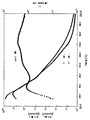
次に、粒子像の輪郭を的確に抽出するための前処理として輪郭強調処理が行われる。そして、画像データをある適当なスレシホールドレベルで2値化する。画像データをある適当なスレシホールドレベルで2値化すると各粒子画像は図8に示すような2値化画像となる。次に、2値化された各粒子画像に対してエッジ点(輪郭を表す輪郭画素)かどうかを判定するとともに、着目しているエッジ点に対して隣り合うエッジ点がどの方向にあるかの情報、すなわちチェインコードを生成する。
次に、各粒子像の投影面積Sと周囲長Lを求める。上記面積Sと周囲長Lを用いて円相当径と円形度を求める。円相当径とは、粒子像の投影面積と同じ面積を持つ円の直径のことであり、円形度Cは、円相当径から求めた円の周囲長を粒子投影像の周囲長で割った値として定義され、次式で算出される。
![]()
The measurement principle of the flow-type particle image analyzer “FPIA-3000 type” (manufactured by Sysmex Corporation) is to take a flowing particle as a still image and perform image analysis. The sample added to the sample chamber is fed into the flat sheath flow cell by a sample suction syringe. The sample fed into the flat sheath flow cell is sandwiched between sheath liquids to form a flat flow. The sample passing through the flat sheath flow cell is irradiated with strobe light at 1/60 second intervals, and the flowing particles can be photographed as a still image. Further, since the flow is flat, the image is taken in a focused state. The particle image is picked up by a CCD camera, and the picked-up image is image-processed with an image processing resolution of 512 × 512 (0.37 μm × 0.37 μm per pixel), the contour of each particle image is extracted, and the particle image Projected area, perimeter, etc. are measured.
The image signal is A / D converted by the image processing unit, captured as image data, and image processing for determining the presence or absence of particles is performed on the stored image data.
Next, contour enhancement processing is performed as preprocessing for accurately extracting the contour of the particle image. Then, the image data is binarized at an appropriate threshold level. When the image data is binarized at an appropriate threshold level, each particle image becomes a binarized image as shown in FIG. Next, it is determined whether each of the binarized particle images is an edge point (contour pixel representing a contour), and in which direction there is an edge point adjacent to the focused edge point. Information, that is, chain code is generated.
Next, the projected area S and the perimeter L of each particle image are obtained. Using the area S and the perimeter L, the equivalent circle diameter and the circularity are obtained. The equivalent circle diameter is the diameter of a circle having the same area as the projected area of the particle image, and the circularity C is a value obtained by dividing the circumference of the circle obtained from the equivalent circle diameter by the circumference of the projected particle image. And is calculated by the following formula.
![]()
粒子像が円形の時に円形度は1.000になり、粒子像の外周の凹凸の程度が大きくなればなるほど円形度は小さい値になる。各粒子の円形度を算出後、円形度0.2〜1.0の範囲を800分割し、その分割点の中心値と測定粒子数を用いて、相加平均により平均円形度の算出を行う。 When the particle image is circular, the circularity is 1.000. The greater the degree of irregularities on the outer periphery of the particle image, the smaller the circularity. After calculating the circularity of each particle, the range of the circularity of 0.2 to 1.0 is divided into 800, and the average circularity is calculated by arithmetic mean using the center value of the dividing points and the number of measured particles. .
具体的な測定方法としては、予め不純固形物を除去したイオン交換水10mlを容器中に用意し、その中に分散剤として界面活性剤(好ましくはアルキルベンゼンスルホン酸塩)を加えた後、更に測定試料0.02gを加え、均一に分散させる。分散手段としては、超音波分散機UH−50型(エスエムテー社製)に振動子として直径5mmのチタン合金チップを装着したものを用い、5分間分散処理を行い、測定用の分散液とする。その際、該分散液の温度が40度以上にならないように適宜冷却する。
測定には、標準対物レンズ(10倍)を搭載した上記フロー式粒子像分析装置を用い、シース液にはパーティクルシース「PSE−900A」(シスメックス社製)を使用した。上記手順に従い調整した分散液を上記フロー式粒子像分析装置に導入し、HPF測定モードで、トータルカウントモードにて3000個のトナー粒子を計測して、粒子解析時の2値化閾値を85%とし、解析粒子径を円相当径2.00μm以上、200.00μm以下に限定し、トナーの平均円形度を求めた。
測定にあたっては、測定開始前に標準ラテックス粒子(例えばDuke Scientific社製5200Aをイオン交換水で希釈)を用いて自動焦点調整を行う。その後、測定開始から2時間毎に焦点調整を実施することが好ましい。
なお、本願実施例では、シスメックス社による校正作業が行われた、シスメックス社が発行する校正証明書の発行を受けたフロー式粒子像分析装置を使用し、解析粒子径を円相当径2.00μm以上、200.00μm以下に限定した以外は、校正証明を受けた時の測定及び解析条件で測定を行った。As a specific measurement method, 10 ml of ion-exchanged water from which impure solids have been removed in advance is prepared in a container, and a surfactant (preferably alkylbenzene sulfonate) is added as a dispersant therein, followed by further measurement. Add 0.02 g of sample and disperse uniformly. As a dispersion means, an ultrasonic disperser UH-50 type (manufactured by SMT Co., Ltd.) equipped with a titanium alloy chip having a diameter of 5 mm as a vibrator is used and subjected to a dispersion treatment for 5 minutes to obtain a dispersion for measurement. In that case, it cools suitably so that the temperature of this dispersion may not become 40 degree | times or more.
For the measurement, the above-mentioned flow type particle image analyzer equipped with a standard objective lens (10 times) was used, and a particle sheath “PSE-900A” (manufactured by Sysmex Corporation) was used as the sheath liquid. The dispersion liquid prepared according to the above procedure is introduced into the flow type particle image analyzer, 3000 toner particles are measured in the total count mode in the HPF measurement mode, and the binarization threshold at the time of particle analysis is 85%. The analysis particle diameter was limited to a circle equivalent diameter of 2.00 μm to 200.00 μm, and the average circularity of the toner was determined.
In the measurement, automatic focus adjustment is performed using standard latex particles (for example, Duke Scientific 5200A diluted with ion-exchanged water) before the measurement is started. Thereafter, it is preferable to perform focus adjustment every two hours from the start of measurement.
In this embodiment, a flow type particle image analyzer which has been issued a calibration certificate issued by Sysmex Corporation, which has been calibrated by Sysmex Corporation, has an analysis particle diameter of 2.00 μm in equivalent circle diameter. The measurement was performed under the measurement and analysis conditions when the calibration certificate was received, except that it was limited to 200.00 μm or less.
本発明におけるトナーの重量平均粒径(D4)は、高精細、高画質の画像を得るという観点から4.0〜9.0μmであることが好ましい。重量平均粒径が上記の範囲内である場合には、部材に対する汚染をより良好に抑制でき、また、良好なドット再現性を得ることができる。トナーの重量平均粒径は、4.0〜8.0μmであることがより好ましい。 The weight average particle diameter (D4) of the toner in the present invention is preferably 4.0 to 9.0 μm from the viewpoint of obtaining a high-definition and high-quality image. When the weight average particle diameter is within the above range, contamination of the member can be suppressed more favorably, and good dot reproducibility can be obtained. The weight average particle diameter of the toner is more preferably 4.0 to 8.0 μm.
重量平均粒径(D4)はコールターカウンターTA−II型あるいはコールターマルチサイザー(コールター社製)の如き方法で測定可能である。具体的には、下記のように測定できる。コールターマルチサイザー(コールター社製)を用い、個数分布、体積分布を出力するインターフェイス(日科機製)及びPC9801パーソナルコンピューター(NEC製)を接続する。電解液は1級塩化ナトリウムを用いて1%NaCl水溶液を調製したものを用いることができ、たとえば、ISOTON R−II(コールターサイエンティフィックジャパン社製)が使用できる。測定手順は以下の通りである。
前記電解水溶液を100〜150ml加え、更に測定試料を2〜20mg加える。試料を懸濁した電解液は超音波分散器で約1〜3分間分散処理を行い前記コールターマルチサイザーにより100μmアパーチャーを用いて、2μm以上のトナー粒子の体積、個数を測定して体積分布と個数分布とを算出する。これより重量平均粒径(D4)を求める。
なお、上記トナーの重量平均粒径(D4)に関する上記の条件は、トナー製造時に風力分級、篩い分けといった粒度調整工程において粒度調整することで満たすことが可能である。また、本発明の好ましい形態である、重合トナーの場合には、分散安定剤の仕込み量で調整することが可能である。The weight average particle diameter (D4) can be measured by a method such as Coulter Counter TA-II type or Coulter Multisizer (manufactured by Coulter Inc.). Specifically, it can be measured as follows. Using a Coulter Multisizer (manufactured by Coulter), an interface (manufactured by Nikka) and a PC 9801 personal computer (manufactured by NEC) are connected to output the number distribution and volume distribution. As the electrolytic solution, a 1% NaCl aqueous solution prepared using primary sodium chloride can be used. For example, ISOTON R-II (manufactured by Coulter Scientific Japan) can be used. The measurement procedure is as follows.
100 to 150 ml of the electrolytic aqueous solution is added, and 2 to 20 mg of a measurement sample is further added. The electrolyte solution in which the sample is suspended is subjected to a dispersion treatment with an ultrasonic disperser for about 1 to 3 minutes, and the volume and number of toner particles of 2 μm or more are measured with the Coulter Multisizer using a 100 μm aperture. Calculate the distribution. From this, the weight average particle diameter (D4) is determined.
The above-mentioned conditions concerning the weight average particle diameter (D4) of the toner can be satisfied by adjusting the particle size in a particle size adjusting process such as air classification and sieving at the time of toner production. In the case of a polymerized toner that is a preferred embodiment of the present invention, it can be adjusted by the amount of the dispersion stabilizer charged.
本発明のトナーは、良好な定着画像を得るために、結着樹脂100質量部に対して0.5〜50質量部、好ましくは、3〜30質量部のワックス成分を含有することが好ましい。更に好ましくは5質量部〜20質量部である。ワックス成分の含有量が上記の範囲内であれば、長期間の保存性を維持しつつ、低温オフセットを良好に抑制することができる。また、他のトナー材料の分散を妨げることがなく、良好な流動性や画像特性を維持できる。 In order to obtain a good fixed image, the toner of the present invention preferably contains 0.5 to 50 parts by mass, preferably 3 to 30 parts by mass of a wax component with respect to 100 parts by mass of the binder resin. More preferably, it is 5 mass parts-20 mass parts. If the content of the wax component is within the above range, low temperature offset can be satisfactorily suppressed while maintaining long-term storage stability. Also, good fluidity and image characteristics can be maintained without disturbing the dispersion of other toner materials.
本発明のトナーに使用可能なワックス成分としては、以下のものが挙げられる。パラフィンワックス、マイクロクリスタリンワックス、ペトロラクタムの如き石油系ワックス及びその誘導体;モンタンワックスおよびその誘導体;フィッシャートロプシュ法による炭化水素ワックス及びその誘導体;ポリエチレンワックス、ポリプロピレンワックスの如きポリオレフィンワックス及びその誘導体;カルナバワックス、キャンデリラワックスの如き天然ワックス及びその誘導体。これらの誘導体には酸化物や、ビニル系モノマーとのブロック共重合物、グラフト変性物を含む。さらには、高級脂肪族アルコール、ステアリン酸、パルミチン酸等の脂肪酸、あるいはその化合物、酸アミドワックス、エステルワックス、ケトン、硬化ヒマシ油及びその誘導体、植物系ワックス、動物性ワックスが挙げられる。この中で特に、離型性に優れるという観点からエステルワックス及び炭化水素ワックスが好ましい。更に好ましくは、トータルの炭素数が同一である化合物が、50〜95質量%でワックス成分に含有されていることが、ワックス純度が高く現像性の観点で、本発明の効果を発現し易い。 Examples of the wax component that can be used in the toner of the present invention include the following. Petroleum wax such as paraffin wax, microcrystalline wax, petrolactam and derivatives thereof; montan wax and derivatives thereof; hydrocarbon wax and derivatives thereof according to the Fischer-Tropsch method; polyolefin wax such as polyethylene wax and polypropylene wax and derivatives thereof; carnauba wax Natural waxes such as candelilla wax and derivatives thereof. These derivatives include oxides, block copolymers with vinyl monomers, and graft modified products. Furthermore, fatty acids such as higher aliphatic alcohols, stearic acid and palmitic acid, or compounds thereof, acid amide waxes, ester waxes, ketones, hydrogenated castor oil and derivatives thereof, plant waxes, and animal waxes. Among these, ester wax and hydrocarbon wax are preferable from the viewpoint of excellent releasability. More preferably, the compound having the same total number of carbon atoms is contained in the wax component in an amount of 50 to 95% by mass, and the effect of the present invention is easily exhibited from the viewpoint of developability with high wax purity.
これらのワックスの中では、示差走査熱量測定装置により測定されるDSC曲線の最大吸熱ピークが40℃〜110℃の範囲にあるものが好ましく、更には45℃〜90℃の範囲にあるものがより好ましい。また、最大吸熱ピークの半値幅は、2〜15℃であることが好ましく、2〜10℃であることがより好ましい。最大吸熱ピークの半値幅とは、吸熱ピークにおけるベースラインからピーク高さの2分の1の値を示す部分の、吸熱チャートの温度幅のことである。半値幅が上記の範囲内である場合、ワックスの結晶性が適度であり、適度な硬度を有するため、感光体や帯電部材への汚染の発生を抑制することができる。 Among these waxes, those having a maximum endothermic peak of the DSC curve measured by the differential scanning calorimeter are preferably in the range of 40 ° C to 110 ° C, and more preferably in the range of 45 ° C to 90 ° C. preferable. Moreover, it is preferable that it is 2-15 degreeC, and, as for the half value width of a maximum endothermic peak, it is more preferable that it is 2-10 degreeC. The half-value width of the maximum endothermic peak is the temperature width of the endothermic chart at a portion showing a half value of the peak height from the base line in the endothermic peak. When the full width at half maximum is within the above range, the wax crystallinity is moderate and the hardness is moderate, so that the occurrence of contamination on the photoreceptor and the charging member can be suppressed.
また、本発明のトナーは、示差走査熱量測定装置により測定されるDSC曲線の70〜120℃の範囲に上記ワックスの融点に起因する最大吸熱ピークを持つことが好ましい。 The toner of the present invention preferably has a maximum endothermic peak due to the melting point of the wax in the range of 70 to 120 ° C. of the DSC curve measured by a differential scanning calorimeter.
DSC曲線は、示差走査熱量測定装置(DSC測定装置)DSC−7(パーキンエルマー社製)を用いてASTM D3418−82に準じて測定する。具体的には、以下のようにして測定を行う。
測定試料は5〜20mg、好ましくは10mgを精密に秤量する。
これをアルミパン中に入れ、リファレンスとして空のアルミパンを用い、測定温度範囲30〜200℃の間で、昇温速度10℃/minで常温常湿下において測定を行う。
この昇温過程で、上記ワックスの吸熱ピーク及び上記トナーの最大吸熱ピークが得られる。The DSC curve is measured according to ASTM D3418-82 using a differential scanning calorimeter (DSC measuring device) DSC-7 (manufactured by PerkinElmer). Specifically, the measurement is performed as follows.
The sample to be measured is precisely weighed 5 to 20 mg, preferably 10 mg.
This is put in an aluminum pan, and an empty aluminum pan is used as a reference, and measurement is performed at a temperature rise rate of 10 ° C./min at a temperature rise rate of 10 ° C./min.
In this temperature raising process, the endothermic peak of the wax and the maximum endothermic peak of the toner are obtained.
本発明におけるトナーのTHF可溶分のGPCでのメインピーク分子量Mpは10,000〜40,000が好ましく、より好ましくは、15,000〜35,000である。メインピーク分子量が上記範囲内である場合、ワックスの染み出しが適度となり、良好な耐高温オフセット性が得られる。また、適度な強度を有するため、良好な現像性や転写性を得ることができる。更に、低温定着性に関しても優れた特性が得られる。
なお、上記トナーのメインピーク分子量Mpに関する上記の条件は、トナー製造時の温度を調整することで満たすことが可能であり、特に本発明の好ましい製造法である重合法でトナーを製造する場合においては、重合条件(温度、開始剤種、開始剤量)を調整することで満たすことが可能である。The main peak molecular weight Mp in GPC of the toner soluble matter in the present invention is preferably 10,000 to 40,000, more preferably 15,000 to 35,000. When the main peak molecular weight is within the above range, the oozing out of the wax becomes appropriate and good high temperature offset resistance can be obtained. Moreover, since it has moderate strength, good developability and transferability can be obtained. Further, excellent characteristics can be obtained with respect to low-temperature fixability.
Note that the above-mentioned conditions relating to the main peak molecular weight Mp of the toner can be satisfied by adjusting the temperature at the time of toner production, and particularly when the toner is produced by a polymerization method which is a preferred production method of the present invention. Can be satisfied by adjusting the polymerization conditions (temperature, initiator type, initiator amount).
本発明におけるトナーのTHF可溶分のメインピーク分子量、重量平均分子量(Mw)及び数平均分子量(Mn)は以下の測定方法で測定される。
測定試料は以下のようにして作成する。
試料とTHFとを約0.5〜5mg/ml(例えば約5mg/ml)の濃度で混合し、室温にて数時間(例えば5〜6時間)放置した後、充分に振とうし、THFと試料を良く混ぜ(試料の合一体がなくなるまで)、更に室温にて12時間以上(例えば24時間)静置する。このとき試料とTHFの混合開始時点から、静置終了の時点までの時間が24時間以上となるようにする。その後、サンプル処理フィルター(ポアサイズ0.45〜0.5μm、例えばマイショリディスクH−25−2 東ソー社製、エキクロディスク25CR ゲルマン サイエンスジャパン社製が好ましく利用できる)を通過させたものをGPCの試料とする。試料濃度は、樹脂成分が0.5〜5mg/mlとなるように調整する。The main peak molecular weight, weight average molecular weight (Mw), and number average molecular weight (Mn) of the THF soluble content of the toner in the present invention are measured by the following measuring methods.
The measurement sample is prepared as follows.
The sample and THF were mixed at a concentration of about 0.5 to 5 mg / ml (for example, about 5 mg / ml), allowed to stand at room temperature for several hours (for example, 5 to 6 hours), and then shaken sufficiently to obtain THF and The sample is mixed well (until the sample is no longer united), and is further allowed to stand at room temperature for 12 hours or longer (for example, 24 hours). At this time, the time from the start of mixing the sample and THF to the end of standing is set to 24 hours or longer. Thereafter, a sample processing filter (pore size 0.45 to 0.5 μm, for example, Mysori Disc H-25-2 manufactured by Tosoh Corp., Excro Disc 25CR manufactured by Gelman Science Japan Co., Ltd. can be preferably used) is passed through GPC. A sample is used. The sample concentration is adjusted so that the resin component is 0.5 to 5 mg / ml.
<測定条件>
装置:高速GPC「HLC8120 GPC」(東ソー社製)
カラム:Shodex KF−801、802、803、804、805、806、807の7連(昭和電工社製)
溶離液 :THF
流速 :1.0ml/min
オーブン温度:40.0℃
試料注入量 :0.10ml
また、試料の分子量の算出にあたっては、標準ポリスチレン樹脂(東ソー社製TSK スタンダード ポリスチレン F−850、F−450、F−288、F−128、F−80、F−40、F−20、F−10、F−4、F−2、F−1、A−5000、A−2500、A−1000、A−500)により作成した分子量較正曲線を使用する。<Measurement conditions>
Equipment: High-speed GPC “HLC8120 GPC” (manufactured by Tosoh Corporation)
Column: Seven series of Shodex KF-801, 802, 803, 804, 805, 806, 807 (manufactured by Showa Denko KK)
Eluent: THF
Flow rate: 1.0 ml / min
Oven temperature: 40.0 ° C
Sample injection volume: 0.10 ml
In calculating the molecular weight of the sample, standard polystyrene resin (TSO Standard Polystyrene F-850, F-450, F-288, F-128, F-80, F-40, F-20, F- manufactured by Tosoh Corporation) was used. 10, F-4, F-2, F-1, A-5000, A-2500, A-1000, A-500).
本発明におけるトナーの示差走査熱量測定装置により測定されるガラス転移温度(Tg)は、30〜58℃であることが好ましい。より好ましくは、40〜55℃である。
また、本発明におけるトナーのTgの測定方法は、基本的にワックスの吸熱ピークを得る方法と同じ装置を用いるが、加熱時にワックスのDSC融点ピークとトナーのTgが重複するケースがあるため、本発明のトナーにおいてはモジュレーティッドモードを用い、以下の条件にて測定し、昇温1回目のDSC曲線のピーク位置から求める。尚、コアバインダー樹脂のガラス転移温度、シェルバインダー樹脂(極性樹脂)のガラス転移温度も同様にして測定する。コアバインダー樹脂のガラス転移温度については、コアバインダー樹脂のみをトナー粒子から単離することが困難であるため、その処方から計算される理論Tgをコアバインダー樹脂のTgとみなしてもよい。The glass transition temperature (Tg) measured by the differential scanning calorimeter of the toner in the present invention is preferably 30 to 58 ° C. More preferably, it is 40-55 degreeC.
The method for measuring the Tg of the toner in the present invention basically uses the same apparatus as the method for obtaining the endothermic peak of the wax, but the DSC melting point peak of the wax and the Tg of the toner may overlap during heating. In the toner of the invention, the modulated mode is used, and measurement is performed under the following conditions, and the toner is obtained from the peak position of the DSC curve at the first temperature rise. In addition, the glass transition temperature of core binder resin and the glass transition temperature of shell binder resin (polar resin) are measured similarly. Regarding the glass transition temperature of the core binder resin, since it is difficult to isolate only the core binder resin from the toner particles, the theoretical Tg calculated from the formulation may be regarded as the Tg of the core binder resin.
<測定条件>
・20℃で5分間平衡を保つ。
・1.0℃/minのモジュレーションをかけ、140℃まで1℃/minで昇温する。
・140℃で5分間平衡を保つ。
・20℃まで降温する。<Measurement conditions>
• Equilibrate at 20 ° C for 5 minutes.
・ Modulation of 1.0 ° C / min is applied, and the temperature is increased to 140 ° C at 1 ° C / min.
• Equilibrate at 140 ° C for 5 minutes.
-Lower the temperature to 20 ° C.
本発明のトナーは、内層(コア)と外層(シェル)との密着性が高いコアシェル構造を有する。このようなコアシェル構造を形成する目的で、シェルを形成する樹脂(シェルバインダー樹脂)として、コアを形成する結着樹脂(コアバインダー樹脂)と同組成のものを含んでいる極性樹脂を用い、懸濁重合法によりトナーを製造することが好ましい。このような設計とすることで、コアバインダー樹脂中にシェルバインダー樹脂が相溶しつつ、相分離が起こるため、内層と外層との界面において、それぞれの成分が相溶した密着性の高いコアシェル構造を有するトナー粒子を得ることができる。
コアバインダー樹脂として、ポリスチレン、スチレン置換体の単重合体、スチレン系共重合体のようなビニル系重合体が用いられている場合、シェルバインダー樹脂としても、ビニル系重合体を用いることが好ましい。
コアバインダー樹脂、或いは、シェルバインダー樹脂として用いることのできるビニル系重合体としては、例えば以下のものが挙げられる。スチレン−p−クロルスチレン共重合体、スチレン−ビニルトルエン共重合体、スチレン−ビニルナフタリン共重合体、スチレン−アクリル酸エステル共重合体、スチレン−アクリル酸エステル−アクリル酸共重合体、スチレン−メタクリル酸エステル−アクリル酸共重合体、スチレン−アクリル酸エステル−メタクリル酸共重合体、スチレン−メタクリル酸エステル−メタクリル酸共重合体、スチレン−メタクリル酸エステル共重合体、スチレン−α−クロルメタクリル酸メチル共重合体、スチレン−アクリロニトリル共重合体、スチレン−ビニルメチルエーテル共重合体、スチレン−ビニルエチルエーテル共重合体、スチレン−ビニルメチルケトン共重合体、スチレン−ブタジエン共重合体、スチレン−イソプレン共重合体、スチレン−アクリロニトリル−インデン共重合体。The toner of the present invention has a core-shell structure with high adhesion between the inner layer (core) and the outer layer (shell). For the purpose of forming such a core-shell structure, a polar resin containing the same composition as the binder resin (core binder resin) forming the core is used as the resin forming the shell (shell binder resin). The toner is preferably produced by a turbid polymerization method. By adopting such a design, the shell binder resin is compatible in the core binder resin and phase separation occurs. Therefore, at the interface between the inner layer and the outer layer, the core shell structure with high adhesion is obtained by compatibilizing each component. Toner particles having the following can be obtained.
When a vinyl polymer such as polystyrene, a styrene-substituted homopolymer, or a styrene copolymer is used as the core binder resin, it is preferable to use a vinyl polymer as the shell binder resin.
Examples of the vinyl polymer that can be used as the core binder resin or the shell binder resin include the following. Styrene-p-chlorostyrene copolymer, styrene-vinyltoluene copolymer, styrene-vinylnaphthalene copolymer, styrene-acrylic acid ester copolymer, styrene-acrylic acid ester-acrylic acid copolymer, styrene-methacrylic acid copolymer Acid ester-acrylic acid copolymer, styrene-acrylic acid ester-methacrylic acid copolymer, styrene-methacrylic acid ester-methacrylic acid copolymer, styrene-methacrylic acid ester copolymer, styrene-α-chloromethyl methacrylate Copolymer, Styrene-acrylonitrile copolymer, Styrene-vinyl methyl ether copolymer, Styrene-vinyl ethyl ether copolymer, Styrene-vinyl methyl ketone copolymer, Styrene-butadiene copolymer, Styrene-isoprene copolymer Coalescence, styrene Acrylonitrile - indene copolymer.
また、コアバインダー樹脂として、フェノール樹脂、マレイン酸樹脂、シリコーン樹脂、ポリエステル樹脂、ポリウレタン樹脂、ポリアミド樹脂、フラン樹脂、エポキシ樹脂、ポリビニルブチラール、テルペン樹脂、クマロンインデン樹脂、石油系樹脂が用いられている場合には、シェルバインダー樹脂としては、ビニル系重合体と上記それぞれの樹脂との変性樹脂が挙げられる。 As the core binder resin, phenol resin, maleic acid resin, silicone resin, polyester resin, polyurethane resin, polyamide resin, furan resin, epoxy resin, polyvinyl butyral, terpene resin, coumarone indene resin, petroleum resin are used. In this case, examples of the shell binder resin include modified resins of a vinyl polymer and the above resins.
シェルバインダー樹脂としては、GPCでのピーク分子量Mpが8,000〜250,000、重量平均分子量Mwが8,000〜260,000、数平均分子量と重量平均分子量との比(Mw/Mn)が1.05〜5.00であるものが好ましい。より好ましくは、ピーク分子量Mpが15,000〜250,000、重量平均分子量Mwが15,000〜260,000であり、更に好ましくは、ピーク分子量Mpが20,000〜100,000、重量平均分子量Mwが20,000〜110,000である。また、ガラス転移温度Tgは80〜120℃であるものが好ましい。更に、酸価は5〜40mgKOH/gであるものが好ましい。
シェルバインダー樹脂の含有量は、重合性単量体又は結着樹脂の100質量部に対して10〜40質量部であることが好ましい。より好ましくは15〜30質量部である。As the shell binder resin, the peak molecular weight Mp in GPC is 8,000 to 250,000, the weight average molecular weight Mw is 8,000 to 260,000, and the ratio of the number average molecular weight to the weight average molecular weight (Mw / Mn) is What is 1.05-5.00 is preferable. More preferably, the peak molecular weight Mp is 15,000 to 250,000 and the weight average molecular weight Mw is 15,000 to 260,000, and more preferably, the peak molecular weight Mp is 20,000 to 100,000, and the weight average molecular weight. Mw is 20,000-110,000. The glass transition temperature Tg is preferably 80 to 120 ° C. Furthermore, the acid value is preferably 5 to 40 mgKOH / g.
The content of the shell binder resin is preferably 10 to 40 parts by mass with respect to 100 parts by mass of the polymerizable monomer or the binder resin. More preferably, it is 15-30 mass parts.
懸濁重合法にてトナー粒子を製造する際には、添加する極性樹脂(シェルバインダー樹脂)が相溶することによりTgが上昇することを考慮して、コアバインダー樹脂を生成するためのモノマーの理論Tgを低く設定し、製造されるトナーのTgが所定の範囲内となるようにすることが好ましい。低い理論Tgで設計した場合には耐熱性(耐ブロッキング性)が低下してしまいやすいが、このように設計することで、耐熱性の低下を抑制できる。そして、現像性、転写性及び定着性の向上を達成でき、従来のトナーよりも良好な特性を得ることが可能となる。
本発明においては、コアバインダー樹脂のガラス転移温度は、10〜45℃であることが好ましく、より好ましくは、15〜40℃である。When producing toner particles by the suspension polymerization method, considering that the Tg increases due to the compatibility of the added polar resin (shell binder resin), the monomer for producing the core binder resin is used. It is preferable to set the theoretical Tg low so that the Tg of the toner to be produced is within a predetermined range. When designed with a low theoretical Tg, the heat resistance (blocking resistance) tends to decrease, but by designing in this way, the decrease in heat resistance can be suppressed. Further, improvement in developability, transferability and fixability can be achieved, and better characteristics than conventional toner can be obtained.
In this invention, it is preferable that the glass transition temperature of core binder resin is 10-45 degreeC, More preferably, it is 15-40 degreeC.
また、メカニズムが明確になっていないが、懸濁重合法によりトナー粒子を製造する際に、モノマー中に芳香族系の有機溶媒(例えばトルエンやキシレン)を添加すると、コアバインダー樹脂中にシェルバインダー樹脂が相溶しつつ、相分離することが促進され、本発明の効果を発揮しやすくなる。 Although the mechanism is not clear, when an aromatic organic solvent (for example, toluene or xylene) is added to the monomer when producing toner particles by suspension polymerization, a shell binder is added to the core binder resin. While the resin is compatible, phase separation is promoted, and the effects of the present invention are easily exhibited.
本発明におけるトナーは、スルホン酸基、スルホン酸塩基又はスルホン酸エステル基の重合体を含有することが好ましい。このような重合体を含有させることによって、トナー担持体の長手方向のトナーコート量が均一となり、感光体上への現像をより忠実に行うことができるようになる。また、同一頁内における均一性が高い画像を得ることができる。この他に平滑性の低い転写材であっても平滑性の高い転写材同様の転写均一性を得ることができる。また、懸濁重合法によってトナー粒子を製造する場合には、水系媒体中の造粒安定性を高めることができる。上記スルホン酸基を有する単量体として、スチレンスルホン酸、2−アクリルアミド−2−メチルプロパンスルホン酸、2−メタクリルアミド−2−メチルプロパンスルホン酸、ビニルスルホン酸、メタクリルスルホン酸が例示できる。そして、これらの単量体が有するスルホン酸基を塩にしたもの、メチル基やエチル基によってエステル化した化合物も用いることができる。
本発明に用いられるスルホン酸基等を含有する重合体は、上記単量体の単重合体であっても構わないが、上記単量体と他の単量体との共重合体であっても構わない。上記単量体と共重合体をなす単量体としては、ビニル系重合性単量体があり、単官能性重合性単量体或いは多官能性重合性単量体を使用することが出来る。The toner in the present invention preferably contains a polymer of a sulfonic acid group, a sulfonic acid group, or a sulfonic acid ester group. By including such a polymer, the toner coat amount in the longitudinal direction of the toner carrier becomes uniform, and development on the photoreceptor can be performed more faithfully. In addition, an image with high uniformity within the same page can be obtained. In addition to this, even with a transfer material having low smoothness, transfer uniformity similar to that of a transfer material having high smoothness can be obtained. In addition, when toner particles are produced by a suspension polymerization method, the granulation stability in an aqueous medium can be improved. Examples of the monomer having a sulfonic acid group include styrene sulfonic acid, 2-acrylamido-2-methylpropane sulfonic acid, 2-methacrylamide-2-methylpropane sulfonic acid, vinyl sulfonic acid, and methacryl sulfonic acid. And what made the sulfonic acid group which these monomers have into a salt, and the compound esterified by the methyl group and the ethyl group can also be used.
The polymer containing a sulfonic acid group and the like used in the present invention may be a homopolymer of the above monomer, but is a copolymer of the above monomer and another monomer. It doesn't matter. As a monomer that forms a copolymer with the above monomer, there is a vinyl polymerizable monomer, and a monofunctional polymerizable monomer or a polyfunctional polymerizable monomer can be used.
単官能性重合性単量体としては、以下のものが挙げられる。スチレン;α−メチルスチレン、β−メチルスチレン、o−メチルスチレン、m−メチルスチレン、p−メチルスチレン、2,4−ジメチルスチレン、p−n−ブチルスチレン、p−tert−ブチルスチレン、p−n−ヘキシルスチレン、p−n−オクチルスチレン、p−n−ノニルスチレン、p−n−デシルスチレン、p−n−ドデシルスチレン、p−メトキシスチレン、p−フェニルスチレンの如きスチレン系重合性単量体;メチルアクリレート、エチルアクリレート、n−プロピルアクリレート、iso−プロピルアクリレート、n−ブチルアクリレート、iso−ブチルアクリレート、tert−ブチルアクリレート、n−アミルアクリレート、n−ヘキシルアクリレート、2−エチルヘキシルアクリレート、n−オクチルアクリレート、n−ノニルアクリレート、シクロヘキシルアクリレート、ベンジルアクリレート、ジメチルフォスフェートエチルアクリレート、ジエチルフォスフェートエチルアクリレート、ジブチルフォスフェートエチルアクリレート、2−ベンゾイルオキシエチルアクリレートの如きアクリル系重合性単量体;メチルメタクリレート、エチルメタクリレート、n−プロピルメタクリレート、iso−プロピルメタクリレート、n−ブチルメタクリレート、iso−ブチルメタクリレート、tert−ブチルメタクリレート、n−アミルメタクリレート、n−ヘキシルメタクリレート、2−エチルヘキシルメタクリレート、n−オクチルメタクリレート、n−ノニルメタクリレート、ジエチルフォスフェートエチルメタクリレート、ジブチルフォスフェートエチルメタクリレートの如きメタクリル系重合性単量体;メチレン脂肪族モノカルボン酸エステル;酢酸ビニル、プロピオン酸ビニル、酪酸ビニル、安息香酸ビニル、ギ酸ビニルの如きビニルエステル;ビニルメチルエーテル、ビニルエチルエーテル、ビニルイソブチルエーテルの如きビニルエーテル;ビニルメチルケトン、ビニルヘキシルケトン、ビニルイソプロピルケトンの如きビニルケトン。
多官能性重合性単量体としては、以下のものが挙げられる。ジエチレングリコールジアクリレート、トリエチレングリコールジアクリレート、テトラエチレングリコールジアクリレート、ポリエチレングリコールジアクリレート、1,6−ヘキサンジオールジアクリレート、ネオペンチルグリコールジアクリレート、トリプロピレングリコールジアクリレート、ポリプロピレングリコールジアクリレート、2,2'−ビス(4−(アクリロキシ・ジエトキシ)フェニル)プロパン、トリメチロールプロパントリアクリレート、テトラメチロールメタンテトラアクリレート、エチレングリコールジメタクリレート、ジエチレングリコールジメタクリレート、トリエチレングリコールジメタクリレート、テトラエチレングリコールジメタクリレート、ポリエチレングリコールジメタクリレート、1,3−ブチレングリコールジメタクリレート、1,6−ヘキサンジオールジメタクリレート、ネオペンチルグリコールジメタクリレート、ポリプロピレングリコールジメタクリレート、2,2'−ビス(4−(メタクリロキシ・ジエトキシ)フェニル)プロパン、2,2'−ビス(4−メタクリロキシ・ポリエトキシ)フェニル)プロパン、トリメチロールプロパントリメタクリレート、テトラメチロールメタンテトラメタクリレート、ジビニルベンゼン、ジビニルナフタリン、ジビニルエーテル。Examples of the monofunctional polymerizable monomer include the following. Styrene; α-methylstyrene, β-methylstyrene, o-methylstyrene, m-methylstyrene, p-methylstyrene, 2,4-dimethylstyrene, pn-butylstyrene, p-tert-butylstyrene, p- Styrenic polymerizable monomers such as n-hexyl styrene, pn-octyl styrene, pn-nonyl styrene, pn-decyl styrene, pn-dodecyl styrene, p-methoxy styrene, p-phenyl styrene Body; methyl acrylate, ethyl acrylate, n-propyl acrylate, iso-propyl acrylate, n-butyl acrylate, iso-butyl acrylate, tert-butyl acrylate, n-amyl acrylate, n-hexyl acrylate, 2-ethylhexyl acrylate, n- Octyl Acryle Acrylic monomers such as methyl methacrylate, n-nonyl acrylate, cyclohexyl acrylate, benzyl acrylate, dimethyl phosphate ethyl acrylate, diethyl phosphate ethyl acrylate, dibutyl phosphate ethyl acrylate, 2-benzoyloxyethyl acrylate; methyl methacrylate , Ethyl methacrylate, n-propyl methacrylate, iso-propyl methacrylate, n-butyl methacrylate, iso-butyl methacrylate, tert-butyl methacrylate, n-amyl methacrylate, n-hexyl methacrylate, 2-ethylhexyl methacrylate, n-octyl methacrylate, n -Nonyl methacrylate, diethyl phosphate ethyl methacrylate, dibutyl phosphate Methacrylic polymerizable monomers such as ethyl acetate; methylene aliphatic monocarboxylic acid esters; vinyl esters such as vinyl acetate, vinyl propionate, vinyl butyrate, vinyl benzoate, vinyl formate; vinyl methyl ether, vinyl ethyl ether, Vinyl ethers such as vinyl isobutyl ether; vinyl ketones such as vinyl methyl ketone, vinyl hexyl ketone and vinyl isopropyl ketone.
The following are mentioned as a polyfunctional polymerizable monomer. Diethylene glycol diacrylate, triethylene glycol diacrylate, tetraethylene glycol diacrylate, polyethylene glycol diacrylate, 1,6-hexanediol diacrylate, neopentyl glycol diacrylate, tripropylene glycol diacrylate, polypropylene glycol diacrylate, 2,2 '-Bis (4- (acryloxy-diethoxy) phenyl) propane, trimethylolpropane triacrylate, tetramethylolmethane tetraacrylate, ethylene glycol dimethacrylate, diethylene glycol dimethacrylate, triethylene glycol dimethacrylate, tetraethylene glycol dimethacrylate, polyethylene glycol Dimethacrylate, 1,3-buty Lenglycol dimethacrylate, 1,6-hexanediol dimethacrylate, neopentyl glycol dimethacrylate, polypropylene glycol dimethacrylate, 2,2′-bis (4- (methacryloxy-diethoxy) phenyl) propane, 2,2′-bis ( 4-methacryloxy-polyethoxy) phenyl) propane, trimethylolpropane trimethacrylate, tetramethylolmethane tetramethacrylate, divinylbenzene, divinylnaphthalene, divinyl ether.
上記スルホン酸基等を含有する重合体は、結着樹脂100質量部に対し0.01〜5.0質量部含有されることが好ましい。より好ましくは、0.1〜3.0質量部である。該スルホン酸基等を含有する重合体の含有量が上記範囲内であれば、トナーに良好な摩擦帯電性を付与することができる。また、懸濁重合時の造粒安定性を良好に高めることができ、得られる粒子の粒度分布がシャープになる。 The polymer containing the sulfonic acid group and the like is preferably contained in an amount of 0.01 to 5.0 parts by mass with respect to 100 parts by mass of the binder resin. More preferably, it is 0.1-3.0 mass parts. If the content of the polymer containing the sulfonic acid group or the like is within the above range, good triboelectric chargeability can be imparted to the toner. Moreover, the granulation stability at the time of suspension polymerization can be improved satisfactorily, and the particle size distribution of the resulting particles becomes sharp.
本発明において、トナー粒子は、水系媒体中で造粒する工程を経て製造された粒子であることが好ましい。 In the present invention, the toner particles are preferably particles produced through a granulation step in an aqueous medium.
水系媒体中でトナー粒子を製造する方法としては、以下の方法が挙げられる。トナー粒子の必須成分から構成される乳化液を水系媒体中で凝集させる乳化凝集法;有機溶媒中にトナー必須成分を溶解させた後、水系媒体中で造粒後有機溶媒を揮発させる懸濁造粒法;トナー必須成分を溶解させた重合性単量体を直接水系媒体中で造粒後重合する懸濁重合法や乳化重合法;さらにその後シード重合を利用しトナーに外層を設ける方法;界面重縮合や液中乾燥に代表されるマイクロカプセル法。 Examples of the method for producing toner particles in an aqueous medium include the following methods. Emulsion aggregation method in which an emulsion composed of essential components of toner particles is aggregated in an aqueous medium; suspension preparation in which the essential components of the toner are dissolved in an organic solvent and then the organic solvent is volatilized after granulation in the aqueous medium. Particle method; Suspension polymerization method or emulsion polymerization method in which a polymerizable monomer in which essential toner components are dissolved is directly granulated in an aqueous medium and then polymerized; Microcapsule method represented by polycondensation and drying in liquid.
これらの中で、本発明の作用効果を発揮しやすいものとして、特に懸濁重合法が好ましい。懸濁重合法においては、重合性単量体に着色剤及びワックス成分(更に必要に応じて重合開始剤、架橋剤、帯電制御剤、その他の添加剤)を均一に溶解または分散せしめて単量体組成物とした後、分散安定剤を含有する連続層(例えば水相)中にこの単量体組成物を適当な撹拌器を用いて分散させ、そして重合反応を行わせ、所望の粒径を有するトナー粒子を得るものである。該トナー粒子は重合終了後、公知の方法によって濾過、洗浄、乾燥を行い、無機微粉体を外添により混合し表面に付着させることで、本発明のトナーを得ることができる。 Among these, the suspension polymerization method is particularly preferable as the one that easily exhibits the effects of the present invention. In the suspension polymerization method, a colorant and a wax component (in addition, a polymerization initiator, a crosslinking agent, a charge control agent, and other additives, if necessary) are uniformly dissolved or dispersed in a polymerizable monomer. After forming the body composition, the monomer composition is dispersed in a continuous layer containing a dispersion stabilizer (for example, an aqueous phase) using an appropriate stirrer, and a polymerization reaction is performed to obtain a desired particle size. The toner particles having the above are obtained. After the polymerization is completed, the toner particles of the present invention can be obtained by filtering, washing and drying by a known method, mixing inorganic fine powders by external addition, and adhering them to the surface.
懸濁重合法でトナー粒子を製造する場合には、個々のトナー粒子形状がほぼ球形に揃っているため、摩擦帯電量の分布も比較的均一となり、良好な現像特性を有するトナーが得られやすい。また外添剤への依存度が少ない高い転写性を維持するトナーが得られやすい。 When toner particles are produced by the suspension polymerization method, since the individual toner particle shapes are almost spherical, the distribution of the triboelectric charge amount becomes relatively uniform, and it is easy to obtain a toner having good development characteristics. . Further, it is easy to obtain a toner that maintains a high transferability with little dependence on external additives.
懸濁重合法によりトナー粒子を製造する際の重合性単量体としては、上記した単官能性重合性単量体、多官能性重合性単量体が挙げられる。 Examples of the polymerizable monomer for producing toner particles by the suspension polymerization method include the above-described monofunctional polymerizable monomer and polyfunctional polymerizable monomer.
多官能性重合性単量体は、架橋剤として作用し、単官能性重合性単量体100質量部に対して0.001〜15質量部の割合で用いることができる。多官能性重合性単量体としては、上記したものに加えて、ジビニルアニリン、ジビニルスルフィド、ジビニルスルホンの如きジビニル化合物や3個以上のビニル基を有する化合物が挙げられる。 The polyfunctional polymerizable monomer acts as a cross-linking agent and can be used at a ratio of 0.001 to 15 parts by mass with respect to 100 parts by mass of the monofunctional polymerizable monomer. Examples of the polyfunctional polymerizable monomer include divinyl compounds such as divinylaniline, divinyl sulfide, and divinyl sulfone, and compounds having three or more vinyl groups, in addition to those described above.
重合開始剤としては、油溶性開始剤及び/又は水溶性開始剤が用いられる。好ましくは、重合反応時の反応温度における半減期が0.5〜30時間のものである。また重合性単量体100質量部に対し0.5〜20質量部の添加量で重合反応を行うと、通常、分子量1万〜4万の間に極大を有する重合体が得られ、適当な強度と溶融特性を有するトナーを得ることができる。 As the polymerization initiator, an oil-soluble initiator and / or a water-soluble initiator is used. Preferably, the half-life at the reaction temperature during the polymerization reaction is 0.5 to 30 hours. When the polymerization reaction is carried out at an addition amount of 0.5 to 20 parts by mass with respect to 100 parts by mass of the polymerizable monomer, a polymer having a maximum between 10,000 and 40,000 is usually obtained. A toner having strength and melting characteristics can be obtained.
重合開始剤の例としては、以下のものが挙げられる。2,2'−アゾビス−(2,4−ジメチルバレロニトリル)、2,2'−アゾビスイソブチロニトリル、1,1'−アゾビス(シクロヘキサン−1−カルボニトリル)、2,2'−アゾビス−4−メトキシ−2,4−ジメチルバレロニトリル、アゾビスイソブチロニトリルの如きアゾ系またはジアゾ系重合開始剤;ベンゾイルパーオキサイド、t−ブチルパーオキシ2−エチルヘキサノエート、t−ブチルパーオキシピバレート、t−ブチルパーオキシイソブチレート、t−ブチルパーオキシネオデカノエート、メチルエチルケトンパーオキサイド、ジイソプロピルパーオキシカーボネート、クメンヒドロパーオキサイド、2,4−ジクロロベンゾイルパーオキサイド、ラウロイルパーオキサイドの如き過酸化物系重合開始剤。特に好ましくは、重合反応中の分解時にエーテル化合物を生成するような重合開始剤である。 The following are mentioned as an example of a polymerization initiator. 2,2′-azobis- (2,4-dimethylvaleronitrile), 2,2′-azobisisobutyronitrile, 1,1′-azobis (cyclohexane-1-carbonitrile), 2,2′-azobis Azo or diazo polymerization initiators such as -4-methoxy-2,4-dimethylvaleronitrile and azobisisobutyronitrile; benzoyl peroxide, t-butylperoxy 2-ethylhexanoate, t-butylper Oxypivalate, t-butylperoxyisobutyrate, t-butylperoxyneodecanoate, methyl ethyl ketone peroxide, diisopropyl peroxycarbonate, cumene hydroperoxide, 2,4-dichlorobenzoyl peroxide, lauroyl peroxide Such peroxide polymerization initiators. Particularly preferred is a polymerization initiator that produces an ether compound upon decomposition during the polymerization reaction.
本発明において、下記構造式(1)あるいは(2)で表されるエーテル化合物を含有することで、特に同一頁内における均一性が高い画像を得ることができる。また、トナー担持体の長手方向のトナーコート量が均一となり、より忠実な現像が可能となる。更に、平滑性の低い転写材であっても平滑性の高い転写材同様の転写均一性を得ることができる。該エーテル化合物は、トナー粒子の製造時に処方として添加して含有させても良いが、重合開始剤の分解物から重合容器内において生じさせることもできる。

上記エーテル化合物は、結着樹脂との相溶性に優れているために、トナー粒子に含有させた場合には、均一に近い状態で分散されて存在すると考えられる。また、酸素原子は電気陰性度が高い元素であるため、トナー中に発生した負電荷を非局在化させる。上記エーテル化合物はこの2つの特徴を有するため、トナーの負電荷を安定化させる。そのため、該エーテル化合物を含有させる効果は、本発明のトナーが負帯電性トナーである場合に特に顕著となる。また、正帯電性トナーにおいては、チャージアップを抑制する効果を発揮する。 Since the ether compound is excellent in compatibility with the binder resin, it is considered that when the ether compound is contained in the toner particles, the ether compound is dispersed in a nearly uniform state. Further, since oxygen atoms are elements having high electronegativity, the negative charges generated in the toner are delocalized. Since the ether compound has these two characteristics, the negative charge of the toner is stabilized. Therefore, the effect of including the ether compound is particularly remarkable when the toner of the present invention is a negatively chargeable toner. Further, the positively chargeable toner exhibits an effect of suppressing charge-up.
また、上記エーテル化合物は三級炭素を有しておりバルキーな構造である。三級炭素を中心とする官能基は立体障害として機能するため、水の影響を受けにくく電荷のリークが抑制される。しかし、酸素原子に結合している炭素が回転運動することにより、立体障害となりうる官能基も動くことができるため、帯電のリークに関与する水分子に対して、完全な立体障害とはならない。その結果、三級炭素を中心とする官能基は、適度な立体障害としての機能を果たす。 The ether compound has tertiary carbon and has a bulky structure. Since the functional group centered on tertiary carbon functions as a steric hindrance, it is hardly affected by water and charge leakage is suppressed. However, when the carbon bonded to the oxygen atom rotates, the functional group that can be sterically hindered can also move, so that the water molecule involved in the charge leakage is not completely sterically hindered. As a result, the functional group centered on the tertiary carbon functions as an appropriate steric hindrance.
したがって、上記極性樹脂と上記エーテル化合物を組み合わせることによって、従来内層樹脂全体の電荷安定化効果に寄与していたものが、外層樹脂中においても電荷安定化効果に寄与することができるようになる。その為、高温高湿環境から低温低湿環境に至るまで、トナー全体としての電荷バランスが優れ、トナー担持体上のトナーコート均一性や、高転写効率維持や、同一頁内の画像の転写均一性や、低い平滑性の転写材への転写均一性に対し優れた効果を発揮する。また、上述の適度な立体障害が、重合性単量体の反応性を適度に制御することが可能となり、本発明の如き粘弾特性を持ったトナーを得るために効果的である。 Therefore, by combining the polar resin and the ether compound, what has conventionally contributed to the charge stabilization effect of the entire inner layer resin can also contribute to the charge stabilization effect in the outer layer resin. Therefore, it has excellent charge balance as a whole toner from high temperature and high humidity environment to low temperature and low humidity environment, uniformity of toner coat on the toner carrier, high transfer efficiency maintenance, and transfer uniformity of images on the same page In addition, it exhibits an excellent effect on the uniformity of transfer to a low smoothness transfer material. Further, the appropriate steric hindrance described above makes it possible to appropriately control the reactivity of the polymerizable monomer, and is effective for obtaining a toner having viscoelastic properties as in the present invention.
上記構造式(1)、(2)で表されるエーテル化合物において、R1乃至R11のいずれかが水素原子である場合には、立体障害としての機能が大幅に低減してしまい、逆に炭素数が7以上のアルキル基である場合には、疎水性と親水性のバランスが著しく変化することや結着樹脂との相溶性が低くなることにより、エーテル化合物を添加する効果が得られなくなる。そして、R1〜R11は、炭素数1〜4のアルキル基であることがより好ましい。In the ether compounds represented by the structural formulas (1) and (2), when any of R 1 to R 11 is a hydrogen atom, the function as steric hindrance is greatly reduced. When the alkyl group has 7 or more carbon atoms, the effect of adding an ether compound cannot be obtained because the balance between hydrophobicity and hydrophilicity is remarkably changed and compatibility with the binder resin is lowered. . R 1 to R 11 are more preferably an alkyl group having 1 to 4 carbon atoms.
上記化合物は、上記のような効果を十分に発現するためには、トナーの質量基準で、5〜1,000ppm含有されていることが好ましい。より好ましくは10〜800ppmであり、さらに好ましくは10〜500ppmである。上記エーテル化合物は、1種以上含有されていればよく、別の構造の上記エーテル化合物が含まれていても良い。その際の含有量は、含有されているエーテル化合物量の総和とする。 The above compound is preferably contained in an amount of 5 to 1,000 ppm based on the mass of the toner in order to sufficiently exhibit the above effects. More preferably, it is 10-800 ppm, More preferably, it is 10-500 ppm. The said ether compound should just contain 1 or more types, and the said ether compound of another structure may be contained. The content at that time is the total amount of the ether compounds contained.
該エーテル化合物の構造の一例として、以下のような構造が挙げられる。
本発明においては、重合性単量体の重合度を制御する為に、公知の連鎖移動剤、重合禁止剤を使用しても良い。 In the present invention, a known chain transfer agent or polymerization inhibitor may be used to control the degree of polymerization of the polymerizable monomer.
本発明に用いられる着色剤は、黒色着色剤として、カーボンブラック又は,以下に示すイエロー/マゼンタ/シアン着色剤を用い各色に調色されたものが利用される。また、懸濁重合法によってトナー粒子を製造する場合には、着色剤の持つ重合阻害性や水相移行性に注意を払う必要があり、着色剤を表面改質(たとえば重合阻害のない疎水化処理)することが好ましい。特に染料やカーボンブラックは、重合阻害性を有しているものが多いので使用の際に注意を要する。 As the colorant used in the present invention, carbon black or a color adjusted to each color using the following yellow / magenta / cyan colorant is used as the black colorant. In addition, when producing toner particles by suspension polymerization, it is necessary to pay attention to the polymerization inhibitory property and water phase migration property of the colorant. Treatment). In particular, since dyes and carbon black have many polymerization-inhibiting properties, care must be taken when using them.
イエロー着色剤としては、縮合アゾ化合物、イソインドリノン化合物、アンスラキノン化合物、アゾ金属錯体、メチン化合物、アリルアミド化合物に代表される化合物が用いられる。具体的には、C.I.ピグメントイエロー12、13、14、15、17、62、74、83、93、94、95、97、109、110、111、120、128、129、138、147、150、155、168、180、185、214が好適に用いられる。 As the yellow colorant, compounds represented by condensed azo compounds, isoindolinone compounds, anthraquinone compounds, azo metal complexes, methine compounds, and allylamide compounds are used. Specifically, C.I. I. Pigment Yellow 12, 13, 14, 15, 17, 62, 74, 83, 93, 94, 95, 97, 109, 110, 111, 120, 128, 129, 138, 147, 150, 155, 168, 180, 185 and 214 are preferably used.
マゼンタ着色剤としては、縮合アゾ化合物、ジケトピロロピロール化合物、アントラキノン、キナクリドン化合物、塩基染料レーキ化合物、ナフトール化合物、ベンズイミダゾロン化合物、チオインジゴ化合物,ペリレン化合物が用いられる。具体的には、C.I.ピグメントレッド2、3、5、6、7、23、48:2、48:3、48:4、57:1、81:1、122、146、166、169、177、184、185、202、206、220、221、238、254、269、C.I.ピグメントバイオレッド19が好適に用いられる。
As the magenta colorant, condensed azo compounds, diketopyrrolopyrrole compounds, anthraquinones, quinacridone compounds, basic dye lake compounds, naphthol compounds, benzimidazolone compounds, thioindigo compounds, and perylene compounds are used. Specifically, C.I. I.
本発明に用いられるシアン着色剤としては、銅フタロシアニン化合物及びその誘導体、アントラキノン化合物、塩基染料レーキ化合物が挙げられる。具体的には、C.I.ピグメントブルー1、7、15、15:1、15:2、15:3、15:4、60、62、66が特に好適に利用される。
Examples of the cyan colorant used in the present invention include copper phthalocyanine compounds and derivatives thereof, anthraquinone compounds, and basic dye lake compounds. Specifically, C.I. I.
これらの着色剤は、単独又は混合し更には固溶体の状態で用いることができる。着色剤は、色相角、彩度、明度、耐光性、OHP透明性、トナー中への分散性の点から選択される。着色剤の添加量は、結着樹脂100質量部に対し1〜20質量部が好適である。 These colorants can be used alone or in combination and further in the form of a solid solution. The colorant is selected from the viewpoints of hue angle, saturation, brightness, light resistance, OHP transparency, and dispersibility in the toner. The addition amount of the colorant is preferably 1 to 20 parts by mass with respect to 100 parts by mass of the binder resin.
本発明のトナーには、帯電特性を安定化するために上記スルホン酸基等を側鎖に持つ高分子の他に、更に他の帯電制御剤を配合しても良い。帯電制御剤としては、公知のものが利用でき、特に帯電スピードが速く、かつ、一定の摩擦帯電量を安定して維持できる帯電制御剤が好ましい。さらに、トナーを直接重合法にて製造する場合には、重合阻害性が低く、水系分散媒体への可溶化物が実質的にない帯電制御剤が特に好ましい。具体的な化合物としては、負帯電制御剤としてサリチル酸、アルキルサリチル酸、ジアルキルサリチル酸、ナフトエ酸、ダイカルボン酸の如き芳香族カルボン酸の金属化合物、アゾ染料あるいはアゾ顔料の金属塩または金属錯体、ホウ素化合物、ケイ素化合物、カリックスアレーンが挙げられる。正帯電制御剤として四級アンモニウム塩、該四級アンモニウム塩を側鎖に有する高分子型化合物、グアニジン化合物、ニグロシン系化合物、イミダゾール化合物が挙げられる。 In addition to the polymer having a sulfonic acid group or the like in the side chain, the toner of the present invention may further contain another charge control agent in order to stabilize the charging characteristics. As the charge control agent, known ones can be used, and in particular, a charge control agent that has a high charging speed and can stably maintain a constant triboelectric charge amount is preferable. Further, when the toner is produced by a direct polymerization method, a charge control agent having a low polymerization inhibition property and substantially free from a solubilized product in an aqueous dispersion medium is particularly preferable. Specific compounds include, as a negative charge control agent, metal compounds of aromatic carboxylic acids such as salicylic acid, alkyl salicylic acid, dialkyl salicylic acid, naphthoic acid, dicarboxylic acid, metal salts or metal complexes of azo dyes or azo pigments, boron compounds , Silicon compounds, calixarene. Examples of the positive charge control agent include a quaternary ammonium salt, a polymer compound having the quaternary ammonium salt in the side chain, a guanidine compound, a nigrosine compound, and an imidazole compound.
これらの帯電制御剤の使用量としては、結着樹脂の種類、他の添加剤の有無、分散方法を含めたトナー製造方法によって決定されるもので、一義的に限定されるものではないが、内部添加する場合は、好ましくは結着樹脂又は重合性単量体100質量部に対して0.1〜10質量部、より好ましくは0.1〜5質量部の範囲で用いられる。また、外部添加する場合、トナー粒子100質量部に対し、好ましくは0.005〜1.0質量部、より好ましくは0.01〜0.3質量部である。 The amount of use of these charge control agents is determined by the toner production method including the type of binder resin, the presence or absence of other additives, and the dispersion method, and is not uniquely limited. When adding internally, it is used in the range of preferably 0.1 to 10 parts by mass, more preferably 0.1 to 5 parts by mass with respect to 100 parts by mass of the binder resin or polymerizable monomer. Further, when externally added, the amount is preferably 0.005 to 1.0 part by mass, more preferably 0.01 to 0.3 part by mass with respect to 100 parts by mass of the toner particles.
懸濁重合する際に用いられる水系媒体には、有機又は無機の分散安定剤を添加することが好ましい。例えば、無機分散安定剤としては、以下のものが挙げられる。リン酸カルシウム、リン酸マグネシウム、リン酸アルミニウム、リン酸亜鉛、炭酸カルシウム、炭酸マグネシウム、水酸化カルシウム、水酸化マグネシウム、水酸化アルミニウム、メタケイ酸カルシウム、硫酸カルシウム、硫酸バリウム、ベントナイト、酸化ケイ素、酸化アルミニウム。有機分散安定剤として、以下のものが挙げられる。ポリビニルアルコール、ゼラチン、メチルセルロース、メチルヒドロキシプロピルセルロース、エチルセルロース、カルボキシメチルセルロースのナトリウム塩、ポリアクリル酸及びその塩、デンプン。分散安定剤は、重合性単量体100質量部に対して、0.2〜20質量部使用することが好ましい。 It is preferable to add an organic or inorganic dispersion stabilizer to the aqueous medium used for suspension polymerization. For example, examples of the inorganic dispersion stabilizer include the following. Calcium phosphate, magnesium phosphate, aluminum phosphate, zinc phosphate, calcium carbonate, magnesium carbonate, calcium hydroxide, magnesium hydroxide, aluminum hydroxide, calcium metasilicate, calcium sulfate, barium sulfate, bentonite, silicon oxide, aluminum oxide. The following are mentioned as an organic dispersion stabilizer. Polyvinyl alcohol, gelatin, methyl cellulose, methyl hydroxypropyl cellulose, ethyl cellulose, sodium salt of carboxymethyl cellulose, polyacrylic acid and its salt, starch. The dispersion stabilizer is preferably used in an amount of 0.2 to 20 parts by mass with respect to 100 parts by mass of the polymerizable monomer.
また、これら分散安定剤の微細な分散のために、0.001〜0.1質量部の界面活性剤を使用してもよい。これは上記分散安定剤の所期の作用を促進するためのものであり、その具体例としては、以下のものが挙げられる。ドデシルベンゼン硫酸ナトリウム、テトラデシル硫酸ナトリウム、ペンタデシル硫酸ナトリウム、オクチル硫酸ナトリウム、オレイン酸ナトリウム、ラウリル酸ナトリウム、ステアリン酸カリウム、オレイン酸カルシウム。 Moreover, you may use 0.001-0.1 mass part surfactant for fine dispersion | distribution of these dispersion stabilizers. This is for accelerating the intended action of the dispersion stabilizer, and specific examples thereof include the following. Sodium dodecylbenzene sulfate, sodium tetradecyl sulfate, sodium pentadecyl sulfate, sodium octyl sulfate, sodium oleate, sodium laurate, potassium stearate, calcium oleate.
無機分散安定剤を用いる場合には、市販のものをそのまま用いても良いが、より細かい粒子を得るために、水系媒体中にて該無機化合物を生成させても良い。例えばリン酸カルシウムの場合、高撹拌下において、リン酸ナトリウム水溶液と塩化カルシウム水溶液を混合するとよい。 When using an inorganic dispersion stabilizer, a commercially available one may be used as it is, but the inorganic compound may be produced in an aqueous medium in order to obtain finer particles. For example, in the case of calcium phosphate, a sodium phosphate aqueous solution and a calcium chloride aqueous solution may be mixed under high stirring.
本発明のトナーは、結着樹脂、着色剤、及びワックス成分を少なくとも含有するトナー粒子と、無機微粉体とを有するトナーであって、無機微粉体は外添されていることが好ましい。
無機微粉体の添加量は、トナー粒子100質量部に対し0.01〜5質量部であることが好ましく、0.1〜4.0質量部であることがより好ましい。添加量が上記の範囲内であれば、定着性の低下を抑制しつつ、十分な流動性の向上効果が得られる。該無機微粉体は、個数平均一次粒径が4〜80nmであることが好ましく、4〜60nmであることがより好ましい。The toner of the present invention is a toner having toner particles containing at least a binder resin, a colorant, and a wax component, and inorganic fine powder, and the inorganic fine powder is preferably externally added.
The addition amount of the inorganic fine powder is preferably 0.01 to 5 parts by mass, more preferably 0.1 to 4.0 parts by mass with respect to 100 parts by mass of the toner particles. When the addition amount is within the above range, a sufficient fluidity improving effect can be obtained while suppressing a decrease in fixing property. The inorganic fine powder preferably has a number average primary particle size of 4 to 80 nm, and more preferably 4 to 60 nm.
無機微粉体としては、酸化チタン粉末、酸化アルミニウム粉末、酸化亜鉛粉末の如き金属酸化物;湿式製法シリカ、乾式製法シリカの如きシリカ微粉末が挙げられる。また、上記金属酸化物やシリカ微粉末をシランカップリング剤、チタンカップリング剤、シリコーンオイルの如き処理剤により表面処理しても良い。更には、アルミドープシリカ、チタン酸ストロンチウム、ハイドロタルサイトが挙げられる。 Examples of the inorganic fine powder include metal oxides such as titanium oxide powder, aluminum oxide powder, and zinc oxide powder; silica fine powder such as wet process silica and dry process silica. The metal oxide or silica fine powder may be surface treated with a treatment agent such as a silane coupling agent, a titanium coupling agent, or silicone oil. Furthermore, aluminum dope silica, strontium titanate, and hydrotalcite are mentioned.
その他にも、外添剤として、フッ化ビニリデン微粉未、ポリテトラフルオロエチレン微粉末の如きフッ素系樹脂粉末;ステアリン酸亜鉛、ステアリン酸カルシウム、ステアリン酸鉛等の如き脂肪酸金属塩を添加することもできる。 In addition, as an external additive, vinylidene fluoride fine powder, fluorine-based resin powder such as polytetrafluoroethylene fine powder; fatty acid metal salts such as zinc stearate, calcium stearate, lead stearate, etc. can be added. .
次に、本発明のトナーを用いた画像形成方法について説明する。
本発明のトナーを適用することのできる画像形成方法における現像方法としては、トナー担持体と静電潜像担持体である感光体の表面とが接触していても非接触であっても良い。ここでは、接触している場合について説明する。Next, an image forming method using the toner of the present invention will be described.
As a developing method in the image forming method to which the toner of the present invention can be applied, the toner carrier and the surface of the photosensitive member as the electrostatic latent image carrier may be in contact or non-contact. Here, the case where it contacts is demonstrated.
トナー担持体としては弾性ローラーを用い、弾性ローラー表面等にトナーをコーティングし、これを感光体表面と接触させて現像する方法を用いることができる。弾性ローラーとしては、弾性層の硬度がASKER−C硬度30〜60度のものが好適に使用される。トナー担持体と感光体表面とを接触させて現像を行う場合には、感光体とトナー層を介して対向する弾性ローラーとの間に現像電界を形成することによって現像が行われる。このため、弾性ローラーの弾性体を中抵抗領域に抵抗制御したり、導電性ローラーの表面層に薄層の絶縁層を設けたりして、感光体表面との導通を防ぎつつ電界を保つ必要がある。また、トナー担持体として、剛体ローラーを用い、感光体をベルトのごときフレキシブルな物とした構成も可能である。トナー担持体の抵抗としては、良好な電界を形成する観点から、102〜109Ω・cmの範囲が好ましい。As the toner carrying member, an elastic roller can be used, and a method can be used in which toner is coated on the surface of the elastic roller or the like and developed by bringing it into contact with the surface of the photoreceptor. As the elastic roller, one having an elastic layer having an ASKER-C hardness of 30 to 60 degrees is preferably used. When development is performed by bringing the toner carrying member into contact with the surface of the photosensitive member, the development is performed by forming a developing electric field between the photosensitive member and an elastic roller facing the toner layer. Therefore, it is necessary to control the resistance of the elastic body of the elastic roller to the middle resistance region, or to provide a thin insulating layer on the surface layer of the conductive roller, and to keep the electric field while preventing conduction with the surface of the photoconductor. is there. Further, a rigid roller may be used as the toner carrying member, and the photosensitive member may be a flexible material such as a belt. The resistance of the toner carrier is preferably in the range of 10 2 to 10 9 Ω · cm from the viewpoint of forming a good electric field.
トナー担持体の表面状態としては、その表面粗度Raを0.2〜3.0μmとなるように設定すると、高画質及び高耐久性の両立に貢献することが可能である。該表面粗度Raはトナー搬送能力及びトナー帯電能力と相関する。該トナー担持体の表面粗度Raを上記の範囲とすることで、トナー担持体表面のトナーの搬送能力を適度に抑制し、該トナー担持体上のトナー層を薄層化することができる。また、該トナー担持体とトナーの接触回数が多くなるため、該トナーの帯電性も改善されるので相乗的に画質が向上する傾向にある。 If the surface roughness Ra of the toner carrier is set to 0.2 to 3.0 μm, it is possible to contribute to both high image quality and high durability. The surface roughness Ra correlates with the toner conveying ability and the toner charging ability. By setting the surface roughness Ra of the toner carrier to the above range, the toner carrying ability on the surface of the toner carrier can be moderately suppressed, and the toner layer on the toner carrier can be thinned. Further, since the number of times of contact between the toner carrier and the toner increases, the chargeability of the toner is also improved, so that the image quality tends to be synergistically improved.
本発明において、トナー担持体の表面粗度Raは、JIS表面粗さ「JIS B 0601」に基づき、表面粗さ測定器(サーフコーダSE−30H、株式会社小坂研究所社製)を用いて測定される中心線平均粗さに相当する。具体的には、粗さ曲線からその中心線の方向に測定長さaとして2.5mmの部分を抜き取り、この抜き取り部分の中心線をX軸、縦倍率の方向をY軸、粗さ曲線をy=f(x)で表したとき、次式によって求められる値をマイクロメートル(μm)で表したものを言う。 In the present invention, the surface roughness Ra of the toner carrier is measured using a surface roughness measuring instrument (Surfcoder SE-30H, manufactured by Kosaka Laboratory Co., Ltd.) based on JIS surface roughness “JIS B 0601”. This corresponds to the centerline average roughness. Specifically, a 2.5 mm portion as the measurement length a is extracted from the roughness curve in the direction of the center line, the center line of this extraction portion is the X axis, the direction of the vertical magnification is the Y axis, and the roughness curve is When expressed by y = f (x), it means a value obtained by the following formula expressed in micrometers (μm).
![]()
![]()
トナー担持体上のトナーコート量は、0.1〜1.5mg/cm2が好ましい。トナーコート量が上記の範囲である場合には、十分な画像濃度が得られ、また均一な摩擦帯電を得ることができる。トナーコート量としては、0.2〜0.9mg/cm2がより好ましい。The toner coat amount on the toner carrier is preferably 0.1 to 1.5 mg / cm 2 . When the toner coat amount is in the above range, a sufficient image density can be obtained, and uniform frictional charging can be obtained. The toner coat amount is more preferably 0.2 to 0.9 mg / cm 2 .
トナー担持体は、感光体との対向部において同方向に回転していてもよいし、逆方向に回転していてもよい。両者の回転が同方向である場合、トナー担持体の周速を感光体の周速に対し1.05〜3.0倍となるように設定することが好ましい。トナー担持体の周速が、上記範囲内である場合には、機械的ストレスによるトナーの劣化やトナー担持体へのトナー固着を抑制しつつ、感光体上のトナーに対する撹拌効果を十分に発揮することができ、良好な画像が得られやすくなる。感光体としては、a−Se、CdS、ZnO2、OPC、a−Siの様な光導電絶縁物質層を持つ感光ドラムもしくは感光ベルトが好適に使用される。The toner carrier may be rotated in the same direction at the portion facing the photoconductor, or may be rotated in the opposite direction. When both rotations are in the same direction, it is preferable to set the peripheral speed of the toner carrier to be 1.05 to 3.0 times the peripheral speed of the photoreceptor. When the peripheral speed of the toner carrying member is within the above range, the stirring effect on the toner on the photosensitive member is sufficiently exhibited while suppressing the deterioration of the toner due to mechanical stress and the toner fixing to the toner carrying member. And a good image can be easily obtained. As the photoreceptor, a photosensitive drum or a photosensitive belt having a photoconductive insulating material layer such as a-Se, CdS, ZnO 2 , OPC, or a-Si is preferably used.
OPC感光体における感光層は、電荷発生物質及び電荷輸送性能を有する物質を同一層に含有する単一層型でもよく、又は、電荷輸送層と電荷発生層を成分とする機能分離型感光層であっても良い。導電性基体上に電荷発生層、次いで電荷輸送層の順で積層されている構造の積層型感光層は好ましい例の一つである。また、有機系感光層の結着樹脂は特に限定されるものではないが、ポリカーボネート樹脂、ポリエステル樹脂、アクリル系樹脂が特に転写性に優れ、感光体へのトナーの融着、外添剤のフィルミングが起こりにくいため好ましい。 The photosensitive layer in the OPC photoreceptor may be a single layer type containing a charge generation material and a substance having charge transport performance in the same layer, or a function separation type photosensitive layer having a charge transport layer and a charge generation layer as components. May be. A laminated photosensitive layer having a structure in which a charge generation layer and then a charge transport layer are laminated in this order on a conductive substrate is one preferred example. The binder resin of the organic photosensitive layer is not particularly limited, but polycarbonate resin, polyester resin, and acrylic resin are particularly excellent in transferability, and the toner can be fused to the photosensitive member and the external additive film can be filled. It is preferable because it is difficult for ming.
次に本発明のトナーを適用し得る画像形成装置について添付図面を参照しながら以下に説明する。 Next, an image forming apparatus to which the toner of the present invention can be applied will be described with reference to the accompanying drawings.
図1において、100は現像装置、109は感光体、105は紙などの被転写体、106は転写部材、107は定着用加圧ローラー、108は定着用加熱ローラー、110は感光体109に接触して直接帯電を行う一次帯電部材を示す。
In FIG. 1, 100 is a developing device, 109 is a photosensitive member, 105 is a transfer target such as paper, 106 is a transfer member, 107 is a fixing pressure roller, 108 is a fixing heating roller, and 110 is in contact with the
一次帯電部材110は、感光体109表面を一様に帯電するものであり、バイアス電源115が接続されている。
The
現像装置100はトナー104を収容しており、静電潜像担持体(感光体)109と接触して矢印方向に回転するトナー担持体102を具備する。さらに、トナー量規制及び帯電付与を行う規制部材としての現像ブレード101と、トナー104をトナー担持体102に付着させ且つトナーへの帯電付与を行うため矢印方向に回転する塗布ローラー103を備えている。トナー担持体102には現像バイアス電源117が接続されている。塗布ローラー103にも図示しないバイアス電源が接続されており、負帯電性トナーを使用する場合は現像バイアスよりも負側に、正帯電性トナーを使用する場合は現像バイアスよりも正側に電圧が設定される。
The developing
転写部材106には感光体109と反対極性の転写バイアス電源116が接続されている。
A transfer
ここで、感光体109とトナー担持体102の接触部分における回転方向の長さ、いわゆる現像ニップ幅は0.2〜8.0mmが好ましい。現像ニップの幅が上記の範囲内であれば、より良好な現像を行うことができ、また感光体の磨耗を抑制することができる。
Here, the length in the rotation direction, that is, the so-called development nip width at the contact portion between the photoconductor 109 and the
トナーコート量は現像ブレード101により制御されるが、この現像ブレード101はトナー層を介してトナー担持体102に接触している。この時の接触圧は、4.9〜49N/m(5〜50gf/cm)が好ましい範囲である。接触圧が上記の範囲である場合には、トナーコート量や摩擦帯電量を適正な範囲に調整しやすく、また、トナー粒子の変形や部材への融着を抑制することができる。
The toner coating amount is controlled by the developing blade 101, and the developing blade 101 is in contact with the
現像ブレード102の自由端部は、好ましいNE長(現像ブレードのトナー担持体に対する当接部から自由端までの長さ)を与える範囲であればどのような形状でもよく、例えば断面形状が直線状のもの以外にも、先端近傍で屈曲したL字形状のものや、先端近傍が球状に膨らんだ形状のもの等が好適に用いられる。
The free end portion of the developing
トナーコート量の規制部材としては、弾性ブレード以外にも、剛性のある金属ブレード等を用いても良い。 In addition to the elastic blade, a rigid metal blade or the like may be used as the toner coating amount regulating member.
弾性の規制部材には、所望の極性にトナーを帯電させるのに適した摩擦帯電系列の材質を選択することが好ましく、シリコーンゴム、ウレタンゴム、NBRの如きゴム弾性体、ポリエチレンテレフタレートの如き合成樹脂弾性体、ステンレス、鋼、リン青銅の如き金属弾性体が使用できる。また、それらの複合体であっても良い。 For the elastic regulating member, it is preferable to select a frictional charging material suitable for charging the toner to a desired polarity. A rubber elastic body such as silicone rubber, urethane rubber or NBR, or a synthetic resin such as polyethylene terephthalate. A metal elastic body such as an elastic body, stainless steel, steel, or phosphor bronze can be used. Moreover, those composites may be sufficient.
また、弾性の規制部材とトナー担持体に耐久性が要求される場合には、金属弾性体に樹脂やゴムをスリーブ当接部に当たるように貼り合わせたり、コーティングしたりしたものが好ましい。 Further, when durability is required for the elastic regulating member and the toner carrier, it is preferable that the metal elastic body is bonded or coated with a resin or rubber so as to contact the sleeve contact portion.
更に、弾性の規制部材中に有機物や無機物を添加してもよく、溶融混合させても良いし、分散させても良い。例えば、金属酸化物、金属粉、セラミックス、炭素同素体、ウィスカー、無機繊維、染料、顔料、界面活性剤などを添加することにより、トナーの帯電性をコントロールできる。特に、弾性体がゴムや樹脂等の成型体の場合には、シリカ、アルミナ、チタニア、酸化錫、ジルコニア、酸化亜鉛等の金属酸化物微粉末、カーボンブラック、一般にトナーに用いられる荷電制御剤等を含有させることも好ましい。 Furthermore, an organic substance or an inorganic substance may be added to the elastic regulating member, and it may be melt-mixed or dispersed. For example, the chargeability of the toner can be controlled by adding a metal oxide, metal powder, ceramics, carbon allotrope, whisker, inorganic fiber, dye, pigment, surfactant or the like. In particular, when the elastic body is a molded body such as rubber or resin, fine metal oxide powders such as silica, alumina, titania, tin oxide, zirconia, and zinc oxide, carbon black, a charge control agent generally used for toners, etc. It is also preferable to contain.
またさらに、規制部材に直流電圧及び/または交流電圧を印加することによっても、トナーへのほぐし作用のため、均一薄層塗布性、均一帯電性がより向上し、充分な画像濃度の達成及び良質の画像を得ることができる。 Furthermore, even when a DC voltage and / or an AC voltage is applied to the regulating member, the uniform thin-layer coating property and the uniform charging property are further improved due to the loosening action on the toner, and sufficient image density is achieved and high quality is achieved. Images can be obtained.
帯電部材としては、非接触式のコロナ帯電器と、ローラー等を用いる接触型の帯電部材があり、いずれのものも用いられる。効率的な均一帯電、シンプル化、低オゾン発生化のためには、接触方式のものが好ましく用いられる。 As the charging member, there are a non-contact type corona charger and a contact type charging member using a roller or the like, and any of them can be used. For efficient uniform charging, simplification, and low ozone generation, a contact type is preferably used.
図1においては、接触型の帯電部材を用いている。 In FIG. 1, a contact-type charging member is used.
図1で用いている一次帯電部材110は、中心の芯金110bとその外周を形成した導電性弾性層110aとを基本構成とする帯電ローラーである。帯電ローラー110は、静電潜像担持体一面に押圧力を持って当接され、静電潜像担持体109の回転に伴い従動回転する。
The
帯電ローラーを用いた時の好ましいプロセス条件としては、ローラーの当接圧が4.9〜490N/m(5〜500gf/cm)で、直流電圧に交流電圧を重畳したものを印加電圧として用いた時には、交流電圧=0.5〜5.0kVpp、交流周波数=50Hz〜5kHz、直流電圧=±0.2〜±1.5kVであり、直流電圧を用いた時には、直流電圧=±0.2〜±5.0kVである。尚、ドラムの削れ量を抑制する観点からは、直流電圧のみを印加電圧として用いることがより好ましい。この他の接触帯電手段としては、帯電ブレードを用いる方法や、導電性ブラシを用いる方法がある。これらの接触帯電手段は、非接触のコロナ帯電に比べて、高電圧が不必要であり、またオゾンの発生が低減するといった点で優れている。接触帯電手段としての帯電ローラーおよび帯電ブレードの材質としては、導電性ゴムが好ましく、その表面に離型性被膜を設けても良い。離型性被膜としては、ナイロン系樹脂、PVDF(ポリフッ化ビニリデン)、PVDC(ポリ塩化ビニリデン)などが適用可能である。 As a preferable process condition when the charging roller is used, the contact pressure of the roller is 4.9 to 490 N / m (5 to 500 gf / cm), and a DC voltage superimposed with an AC voltage is used as an applied voltage. Sometimes AC voltage = 0.5 to 5.0 kVpp, AC frequency = 50 Hz to 5 kHz, DC voltage = ± 0.2 to ± 1.5 kV, and when DC voltage is used, DC voltage = ± 0.2 to ± 5.0 kV. Note that it is more preferable to use only the DC voltage as the applied voltage from the viewpoint of suppressing the amount of scraping of the drum. Other contact charging means include a method using a charging blade and a method using a conductive brush. These contact charging means are superior to non-contact corona charging in that a high voltage is unnecessary and generation of ozone is reduced. The material of the charging roller and charging blade as the contact charging means is preferably conductive rubber, and a release coating may be provided on the surface thereof. As the releasable coating, nylon resin, PVDF (polyvinylidene fluoride), PVDC (polyvinylidene chloride), and the like are applicable.
尚、図1に記載の画像形成装置の説明として、接触帯電手段について述べたが、その他の構成の画像形成装置においても接触帯電手段を用いる場合には、同様の装置及び条件を用いることができる。 As the description of the image forming apparatus shown in FIG. 1, the contact charging unit has been described. However, in the case of using the contact charging unit in an image forming apparatus having another configuration, the same apparatus and conditions can be used. .
一次帯電工程に次いで、発光素子からの露光123によって感光体109上に情報信号に応じた静電潜像を形成し、トナー担持体102と当接する位置においてトナーにより静電潜像を現像し可視像化する。さらに、本発明の画像形成方法において、特に感光体上にデジタル潜像を形成した現像システムと組み合わせることで、潜像を乱さないためにドット潜像に対して忠実に現像することが可能となる。該可視像は転写部材106により被転写体105に転写され、加熱ローラー108と加圧ローラー107の間を通過して定着され、定着画像を得る。なお、加熱加圧定着手段としては、ハロゲンヒーター等の発熱体を内蔵した加熱ローラーとこれと押圧力をもって圧接された弾性体の加圧ローラーを基本構成とする熱ローラー方式以外に、フィルムを介してヒーターにより加熱定着する方式も用いられる。
Following the primary charging step, an electrostatic latent image corresponding to the information signal is formed on the
一方、転写されずに感光体109上に残った転写残トナーは、感光体109の表面に当接されるクリーニングブレードを有するクリーナー138で回収され、感光体109はクリーニングされる。
On the other hand, the untransferred toner remaining on the
更に、本発明のトナーを用いた画像形成方法及び装置ユニットに関して図面を用いて説明する。 Further, an image forming method and an apparatus unit using the toner of the present invention will be described with reference to the drawings.
図2及び図3には、本発明の画像形成方法を中間転写体を用いて多重トナー像を記録材に一括転写する画像形成装置の概略図を示す。 2 and 3 are schematic views of an image forming apparatus that collectively transfers multiple toner images onto a recording material using an intermediate transfer member in the image forming method of the present invention.
潜像担持体としての静電潜像担持体(感光体ドラム)1の表面に、帯電バイアス電圧が印加された帯電ローラー2を回転させながら接触させて、感光体ドラム表面を一次帯電し、その後、露光手段としての光源装置Lより発せられたレーザー光Eにより、感光体ドラム1上に第1の静電潜像を形成する。形成された第1の静電潜像は、回転可能なロータリーユニット24に設けられている第1の現像装置としてブラック現像装置4Bk中のブラックトナーにより現像され、ブラックトナー像が形成される。感光体ドラム1上に形成されたブラックトナー像は、中間転写ドラムの導電性支持体に印加される転写バイアス電圧の作用により、中間転写ドラム5上に静電的に一次転写される。次に、上記と同様にして感光体ドラム1の表面に第2の静電潜像を形成し、ロータリーユニット24を回転して、第2の現像装置としてのイエロー現像装置4Y中のイエロートナーにより現像してイエロートナー像を形成し、ブラックトナー像が一次転写されている中間転写ドラム5上にイエロートナー像を静電的に一次転写する。同様にして、第3の静電潜像を形成し、ロータリーユニット24を回転して、第3の現像装置としてのマゼンタ現像装置4M中のマゼンタトナーにより現像し、更に、第4の静電潜像を形成し、ロータリーユニット24を回転して、第4の現像装置としてシアン現像装置4C中のシアントナーにより、順次一次転写を行って、中間転写ドラム5上に各色のトナー像をそれぞれ一次転写する。中間転写ドラム5上に一次転写された多重トナー像は、記録材Pを介して反対側に位置する第2の転写装置8からの転写バイアス電圧の作用により、記録材Pの上に静電的に一括に二次転写される。記録材P上に二次転写された多重トナー像は加熱ローラー9a及び加圧ローラー9bを有する定着装置9により記録材Pに加熱定着される。転写後に感光体ドラム1の表面上に残存する転写残トナーは、感光体ドラム1の表面に当接するクリーニングブレードを有するクリーナー6で回収され、感光体ドラム1はクリーニングされる。
The surface of the electrostatic latent image carrier (photosensitive drum) 1 as a latent image carrier is brought into contact with the surface of the
感光体ドラム1から中間転写ドラム5への一次転写は、第1の転写装置としての中間転写ドラム5の導電性支持体に、図示しない電源より転写バイアスを印加することによって、トナー画像の転写が行われる。
In the primary transfer from the
中間転写ドラム5は、剛体である導電性支持体5aと、表面を覆う弾性層5bよりなる。
The
導電性支持体5aとしては、アルミニウム、鉄、銅及びステンレス等の金属や合金、及びカーボンや金属粒子等を分散した導電性樹脂等を用いることができ、その形状としては円筒状や、円筒の中心に軸を貫通したもの、円筒の内部に補強を施したもの等が挙げられる。 As the conductive support 5a, a metal or an alloy such as aluminum, iron, copper, and stainless steel, and a conductive resin in which carbon or metal particles are dispersed can be used. The thing which penetrated the axis | shaft in the center, the thing which gave reinforcement to the inside of a cylinder, etc. are mentioned.
弾性層5bとしては、以下の材料で形成されたものが挙げられる。スチレン−ブタジエンゴム、ハイスチレンゴム、ブタジエンゴム、イソプレンゴム、エチレン−プロピレン共重合体、EPDM(エチレンプロピレンジエンの3元共重合体)、ニトリルブタジエンゴム(NBR)、クロロプレンゴム、ブチルゴム、シリコーンゴム、フッ素ゴム、ニトリルゴム、ウレタンゴム、アクリルゴム、エピクロロヒドリンゴム及びノルボルネンゴム等のエラストマーゴム。ポリオレフィン系樹脂、シリコーン樹脂、フッ素系樹脂、ポリカーボネート等の樹脂及びこれらの共重合体や混合物を用いても良い。
Examples of the
また、弾性層のさらに表面に、潤滑性、はっ水性の高い滑剤をバインダー中に分散した表面層を設けても良い。 Further, a surface layer in which a lubricant having high lubricity and water repellency is dispersed in a binder may be provided on the surface of the elastic layer.
滑剤としては以下のものが挙げられる。各種フッ素ゴム、フッ素エラストマー、黒鉛やグラファイトにフッ素を結合したフッ化炭素及びポリテトラフルオロエチレン、ポリフッ化ビニルデン、エチレン−テトラフルオロエチレン共重合体及びテトラフルオロエチレン−パーフルオロアルキルビニルエーテル共重合体等のフッ素化合物、シリコーン樹脂、シリコーンゴム、シリコーンエラストマー等のシリコーン系化合物、ポリエチレン、ポリプロピレン、ポリスチレン、アクリル樹脂、ポリアミド樹脂、フェノール樹脂及びエポキシ樹脂。 Examples of the lubricant include the following. Various fluoro rubbers, fluoroelastomers, fluorinated carbon and polytetrafluoroethylene, polyvinylidene fluoride, ethylene-tetrafluoroethylene copolymer and tetrafluoroethylene-perfluoroalkyl vinyl ether copolymer in which fluorine is bonded to graphite or graphite, etc. Silicone compounds such as fluorine compounds, silicone resins, silicone rubbers, silicone elastomers, polyethylene, polypropylene, polystyrene, acrylic resins, polyamide resins, phenol resins and epoxy resins.
また、表面層のバインダー中に、抵抗を制御するために導電剤を適時添加しても良い。導電剤としては、各種の導電性無機粒子及びカーボンブラック、イオン系導電剤、導電性樹脂及び導電性粒子分散樹脂が挙げられる。 In addition, a conductive agent may be added to the surface layer binder in order to control resistance. Examples of the conductive agent include various conductive inorganic particles and carbon black, an ionic conductive agent, a conductive resin, and a conductive particle-dispersed resin.
中間転写ドラム5上に形成された多重トナー像は、第2の転写部材8により記録材P上に一括に二次転写されるが、転写手段としてはコロナ帯電器の如き非接触静電転写手段、或いは、転写ローラー及び転写ベルトの如き接触静電転写手段が使用可能である。
The multiple toner images formed on the
転写ローラーを用いる場合、中間転写ドラムの弾性層の体積固有抵抗値よりも転写ローラーの弾性層の体積固有抵抗値をより小さく設定することで転写ローラーへの印加電圧が軽減でき、転写材上に良好なトナー像を形成できると共に転写材の中間転写体への巻き付きを防止することができる。特に中間転写体の弾性層の体積固有抵抗値が転写ローラーの弾性層の体積固有抵抗値より10倍以上であることが特に好ましい。 When using a transfer roller, the voltage applied to the transfer roller can be reduced by setting the volume resistivity of the elastic layer of the transfer roller smaller than the volume resistivity of the elastic layer of the intermediate transfer drum. A good toner image can be formed and winding of the transfer material around the intermediate transfer member can be prevented. In particular, the volume specific resistance value of the elastic layer of the intermediate transfer member is particularly preferably 10 times or more than the volume specific resistance value of the elastic layer of the transfer roller.
中間転写ドラム及び転写ローラーの硬度は、JIS K−6301に準拠し測定される。本発明に用いられる中間転写ドラムは、10〜40度の範囲の弾性層から構成されることが好ましく、一方、転写ローラーの弾性層の硬度は、中間転写ドラムの弾性層の硬度より硬く、41〜80度の値を有するものが中間転写ドラムへの転写材の巻き付きを防止する上で好ましい。中間転写ドラムと転写ローラーの硬度が逆になると、転写ローラー側に凹部が形成され、中間転写ドラムへの転写材の巻き付きが発生しやすい。 The hardness of the intermediate transfer drum and the transfer roller is measured according to JIS K-6301. The intermediate transfer drum used in the present invention is preferably composed of an elastic layer in the range of 10 to 40 degrees, while the hardness of the elastic layer of the transfer roller is harder than the hardness of the elastic layer of the intermediate transfer drum. Those having a value of ˜80 degrees are preferable for preventing the transfer material from being wound around the intermediate transfer drum. When the hardness of the intermediate transfer drum and that of the transfer roller are reversed, a recess is formed on the transfer roller side, and the transfer material is easily wound around the intermediate transfer drum.
定着装置9としては、加熱ローラー9aと加圧ローラー9bを有する熱ローラー定着装置に替えて、記録材P上のトナー像に接するフィルムを加熱することにより、記録材P上のトナー像を加熱し、記録材Pに多重トナー像を加熱定着するフィルム加熱定着装置を用いることもできる。
The fixing
図2に示した画像形成装置が用いている中間転写体としての中間転写ドラムに代えて、中間転写ベルトを用いて多重トナー像を記録材に一括転写することも可能である。中間転写ベルトの構成について、図3に示す。 Instead of the intermediate transfer drum as the intermediate transfer member used in the image forming apparatus shown in FIG. 2, it is also possible to batch transfer multiple toner images onto a recording material using an intermediate transfer belt. The configuration of the intermediate transfer belt is shown in FIG.
静電潜像担持体(感光ドラム)1上に形成担持されたトナー画像は、感光ドラム1と中間転写ベルト310とのニップ部を通過する過程で、一次転写ローラー312から中間転写ベルト310に印加される一次転写バイアスにより形成される電界により、中間転写ベルト310の外周面に順次一次転写される。311は中間転写ベルト310を掛け渡すローラーである。
The toner image formed and supported on the electrostatic latent image carrier (photosensitive drum) 1 is applied from the
感光ドラム1から中間転写ベルト310への第1〜第4色のトナー画像の順次重畳転写のための一次転写バイアスは、トナーとは逆極性で、バイアス電源314から印加される。
A primary transfer bias for sequentially superimposing and transferring toner images of the first to fourth colors from the
感光ドラム1から中間転写ベルト310への第1〜第3色のトナー画像の一次転写工程において、二次転写ローラー313b及びクリーニング用帯電部材309は中間転写ベルト310から離間することも可能である。
In the primary transfer process of the first to third color toner images from the
313bは二次転写ローラーで、二次転写対向ローラー313aに対応し平行に軸受させて中間転写ベルト310の下面部に離間可能な状態に配設してある。
中間転写ベルト310上に転写された多色カラートナー画像の転写材Pへの転写は、二次転写ローラー313bが中間転写ベルト310に当接されると共に、中間転写ベルト310と二次転写ローラー313bとの当接ニップに所定のタイミングで転写材Pが給送され、二次転写バイアスがバイアス電源316から二次転写ローラー313bに印加される。この二次転写バイアスにより中間転写ベルト310から転写材Pへ多色カラートナー画像が二次転写される。
When the multi-color toner image transferred onto the
転写材Pへの画像転写終了後、中間転写ベルト310にはクリーニング用帯電部材309が当接され、感光ドラム1とは逆極性のバイアスをバイアス電源315から印加することにより、転写材Pに転写されずに中間転写ベルト310上に残留しているトナー(転写残トナー)に感光ドラム1と逆極性の電荷が付与される。
After the image transfer to the transfer material P is completed, a
前記転写残トナーは、感光ドラム1とのニップ部およびその近傍において感光ドラム1に静電的に転写されることにより、中間転写体がクリーニングされる。
The transfer residual toner is electrostatically transferred to the
中間転写ベルトは、ベルト形状の基層と基層の上に設けられる表面処理層よりなる。なお、表面処理層は複数の層により構成されていても良い。基層及び表面処理層には、ゴム、エラストマー、樹脂を使用することができる。 The intermediate transfer belt includes a belt-shaped base layer and a surface treatment layer provided on the base layer. The surface treatment layer may be composed of a plurality of layers. Rubber, elastomer, or resin can be used for the base layer and the surface treatment layer.
ゴム及びエラストマーとしては、以下のものが挙げられる。天然ゴム、イソプレンゴム、スチレン−ブタジエンゴム、ブタジエンゴム、ブチルゴム、エチレン−プロピレンゴム、エチレン−プロピレンターポリマー、クロロプレンゴム、クロロスルホン化ポリエチレン、塩素化ポリエチレン、アクリロニトリルブタジエンゴム、ウレタンゴム、シンジオタクチック1,2−ポリブタジエン、エピクロロヒドリンゴム、アクリルゴム、シリコーンゴム、フッ素ゴム、多硫化ゴム、ポリノルボルネンゴム、水素化ニトリルゴム及び熱可塑性エラストマー(例えばポリスチレン系、ポリオレフィン系、ポリ塩化ビニル系、ポリウレタン系、ポリアミド系、ポリエステル系及びフッ素樹脂系等)。これらの群より選ばれる1種類あるいは2種類以上を使用することができる。 The following are mentioned as rubber | gum and an elastomer. Natural rubber, isoprene rubber, styrene-butadiene rubber, butadiene rubber, butyl rubber, ethylene-propylene rubber, ethylene-propylene terpolymer, chloroprene rubber, chlorosulfonated polyethylene, chlorinated polyethylene, acrylonitrile butadiene rubber, urethane rubber, syndiotactic 1 , 2-Polybutadiene, epichlorohydrin rubber, acrylic rubber, silicone rubber, fluorine rubber, polysulfide rubber, polynorbornene rubber, hydrogenated nitrile rubber, and thermoplastic elastomer (eg, polystyrene, polyolefin, polyvinyl chloride, polyurethane) , Polyamide series, polyester series and fluororesin series). One type or two or more types selected from these groups can be used.
また、樹脂としては、ポリオレフィン系樹脂、シリコーン樹脂、フッ素系樹脂、ポリカーボネートの如き樹脂を使用することができる。これら樹脂の共重合体や混合物を用いても良い。 As the resin, a resin such as a polyolefin resin, a silicone resin, a fluorine resin, or a polycarbonate can be used. A copolymer or a mixture of these resins may be used.
基層としては、織布形状、不織布形状、糸状、フィルム形状をした芯体層の片面あるいは両面に、上述のゴム、エラストマー、樹脂を被覆、浸漬、噴霧したものを使用しても良い。 As the base layer, one obtained by coating, dipping, or spraying the above-described rubber, elastomer, or resin on one side or both sides of a core layer having a woven fabric shape, a nonwoven fabric shape, a thread shape, or a film shape may be used.
芯体層を構成する材料は、以下のものが挙げられる。綿、絹、麻及び羊毛等の天然繊維;キチン繊維、アルギン酸繊維及び再生セルロース繊維等の再生繊維;アセテート繊維等の半合成繊維;ポリエステル繊維、ナイロン繊維、アクリル繊維、ポリオレフィン繊維、ポリビニルアルコール繊維、ポリ塩化ビニル繊維、ポリ塩化ビニリデン繊維、ポリウレタン繊維、ポリアルキルパラオキシベンゾエート繊維、ポリアセタール繊維、アラミド繊維、ポリフロロエチレン繊維及びフェノール繊維等の合成繊維;炭素繊維、ガラス繊維及びボロン繊維等の無機繊維;鉄繊維及び銅繊維等の金属繊維。これらの群より選ばれる1種あるいは2種以上を用いることができる。 Examples of the material constituting the core layer include the following. Natural fibers such as cotton, silk, hemp and wool; regenerated fibers such as chitin fiber, alginate fiber and regenerated cellulose fiber; semi-synthetic fibers such as acetate fiber; polyester fiber, nylon fiber, acrylic fiber, polyolefin fiber, polyvinyl alcohol fiber, Synthetic fibers such as polyvinyl chloride fibers, polyvinylidene chloride fibers, polyurethane fibers, polyalkyl paraoxybenzoate fibers, polyacetal fibers, aramid fibers, polyfluoroethylene fibers and phenol fibers; inorganic fibers such as carbon fibers, glass fibers and boron fibers; Metal fibers such as iron fiber and copper fiber. One or more selected from these groups can be used.
さらに、中間転写ベルトの抵抗値を調節するために基層および表面処理層中に導電剤を添加しても良い。導電剤としては以下のものが挙げられる。カーボン;アルミニウムやニッケルの如き金属粉末;酸化チタンの如き金属酸化物;4級アンモニウム塩含有ポリメタクリル酸メチル;ポリビニルアニリン、ポリビニルピロール、ポリジアセチレン、ポリエチレンイミン、含硼素高分子化合物及びポリピロールの如き導電性高分子化合物。これらの群より選ばれる1種あるいは2種以上を用いることができる。 Further, a conductive agent may be added to the base layer and the surface treatment layer in order to adjust the resistance value of the intermediate transfer belt. Examples of the conductive agent include the following. Carbon; Metal powder such as aluminum and nickel; Metal oxide such as titanium oxide; Polymethyl methacrylate containing quaternary ammonium salt; Conductivity such as polyvinylaniline, polyvinylpyrrole, polydiacetylene, polyethyleneimine, boron-containing polymer compound and polypyrrole Polymeric compounds. One or more selected from these groups can be used.
また、中間転写ベルト表面の滑り性を上げ、転写性を向上するために必要に応じて滑剤を添加しても良い。滑剤としては、中間転写ドラムの弾性層に用いるものと同様の滑剤を用いることができる。 Further, a lubricant may be added as necessary in order to increase the slipperiness of the intermediate transfer belt surface and improve the transferability. As the lubricant, the same lubricant as that used for the elastic layer of the intermediate transfer drum can be used.
次に、複数画像形成部にて各色のトナー画像をそれぞれ形成し、これを同一転写材に順次重ねて転写するようにした画像形成方法について図4に沿って説明する。 Next, an image forming method will be described with reference to FIG. 4 in which a toner image of each color is formed by a plurality of image forming units and this is sequentially transferred onto the same transfer material.
図4に示される画像形成装置においては、第1、第2、第3及び第4の画像形成部29a、29b、29c、29dが並設されており、各画像形成部はそれぞれ専用の静電潜像担持体、いわゆる感光ドラム19a、19b、19c及び19dを具備している。
In the image forming apparatus shown in FIG. 4, first, second, third, and fourth
感光ドラム19a乃至19dの外周側には、帯電手段30a、30b、30cおよび30d、潜像形成手段23a、23b、23c及び23d、現像手段17a、17b、17c及び17d、転写手段(転写用放電手段)24a、24b、24c及び24d、ならびにクリーニング手段18a、18b、18c及び18dが配置されている。
On the outer peripheral side of the
このような構成にて、先ず、第1画像形成部29aの感光ドラム19aが帯電手段30aによって帯電され、そして潜像形成手段23aによって原稿画像における、例えばイエロー成分色の潜像が形成される。該潜像は現像手段17aのイエロートナーを有する現像剤で可視画像とされ、転写手段24aにて、転写材としての記録材Sに転写される。
With such a configuration, first, the
上記のようにイエロー画像が転写材Sに転写されている間に、第2画像形成部29bではマゼンタ成分色の潜像が感光ドラム19b上に形成され、続いて現像手段17bのマゼンタトナーを有する現像剤で可視画像とされる。この可視画像(マゼンタトナー像)は、上記の第1画像形成部29aでの転写が終了した転写材Sが転写部24bに搬入されたときに、該転写材Sの所定位置に重ねて転写される。
As described above, while the yellow image is transferred to the transfer material S, the second
以下、上記と同様な方法により第3、第4の画像形成部29c、29dによってシアン色、ブラック色の画像形成が行なわれ、上記同一の転写材Sに、シアン色,ブラック色を重ねて転写する。このような画像形成プロセスが終了した後、転写材Sは搬送ベルト25により定着手段22に搬送され、転写材S上の画像を定着する。これによって転写材S上には多色画像が得られるのである。転写が終了した各感光ドラム19a、19b、19c及び19dはクリーニング手段18a、18b、18c及び18dにより残留トナーを除去され、引き続き一連の画像形成プロセスが繰り返される。
Thereafter, cyan and black images are formed by the third and fourth
この画像形成装置において、転写材を搬送する搬送手段として加工の容易性及び耐久性の観点からテトロン(登録商標)繊維のメッシュを用いた搬送ベルトや、ポリエチレンテレフタレート系樹脂、ポリイミド系樹脂、ウレタン系樹脂の如き薄い誘電体シートを用いた搬送ベルトが好ましく利用される。 In this image forming apparatus, a transport belt using a mesh of Tetoron (registered trademark) fiber as a transport means for transporting a transfer material, a polyethylene terephthalate resin, a polyimide resin, a urethane system from the viewpoint of ease of processing and durability. A conveyor belt using a thin dielectric sheet such as resin is preferably used.
一般に、このような搬送ベルトは体積抵抗が高く、カラー画像形成において数回の転写を繰り返す過程で搬送ベルトの帯電量が増加してしまうため、均一な転写を維持するためには各転写の都度、転写電流を順次増加させる必要があるが、本発明のトナーは転写性が優れているので、転写を繰り返す毎に搬送手段の帯電が増しても、各転写工程において同じ転写電流で、均一度合いの高い転写を行うことができ、高品位な画像が得られる。 In general, such a conveyance belt has a high volume resistance, and the charge amount of the conveyance belt increases in the process of repeating the transfer several times during color image formation. Therefore, in order to maintain uniform transfer, The transfer current needs to be increased sequentially, but the toner of the present invention has excellent transferability. Therefore, even if the charge of the conveying means increases every time the transfer is repeated, the transfer current is uniform at each transfer step with the same transfer current. Transfer can be performed, and a high-quality image can be obtained.
転写材Sが第4画像形成部29dを通過すると、AC電圧が除電器20に加えられ、転写材Sは除電され、ベルト25から分離され、その後、定着器22に入り、画像定着され、排出口26から排出される。
When the transfer material S passes through the fourth
図5は、中間転写ドラムを用い中間転写ドラム上に一次転写された4色のカラートナー画像を記録材に一括して二次転写する際の二次転写手段として、転写ベルトを用いた画像形成装置の説明図である。 FIG. 5 shows an image formation using a transfer belt as a secondary transfer unit when a color toner image of four colors transferred onto the intermediate transfer drum using the intermediate transfer drum is secondarily transferred to a recording material. It is explanatory drawing of an apparatus.
図5に示す装置システムにおいて、現像装置244−1、244−2、244−3、244−4には、それぞれシアントナーを有する現像剤、マゼンタトナーを有する現像剤、イエロートナーを有する現像剤及びブラックトナーを有する現像剤が導入されている。感光体241を帯電手段によって帯電し、更に露光243することによって静電荷像を形成し、該静電荷像を現像装置244−1〜244−4を用いて現像し、各色トナー像を静電潜像担持体(感光体)241上に順次形成する。また、感光体241は図示しない駆動装置によって矢印方向に回転される。
In the apparatus system shown in FIG. 5, the developing devices 244-1, 244-2, 244-3, and 244-4 include a developer having cyan toner, a developer having magenta toner, a developer having yellow toner, and A developer having black toner has been introduced. The
帯電工程では、中心の芯金242bとその外周を形成した導電性弾性層242aとを基本構成とする帯電ローラー242が用いられている。帯電ローラー242は、感光体241面に押圧力をもって圧接され、感光体241の回転に伴い従動回転する。
In the charging step, a charging roller 242 having a basic configuration of a central cored bar 242b and a conductive
感光体上のトナー像は、電圧(例えば、±0.1〜±5kV)が印加されている中間転写ドラム245に転写される。転写後の感光体表面は、クリーニングブレード248を有するクリーニング手段249でクリーニングされる。
The toner image on the photoreceptor is transferred to an
中間転写ドラム245は、前述したものと同様の中間転写ドラムを用いることができる。尚、245bは、剛体である導電性支持体であり、245aは、その表面を覆う弾性層である。
As the
中間転写ドラム245は感光体241に対して並行に軸受けさせて感光体241の下面部に接触させて配設してあり、感光体241と同じ周速度で矢印の反時計方向に回転する。
The
感光体241の面に形成担持された第1色のトナー像が、感光体241と中間転写ドラム245とが接する転写ニップ部を通過する過程で中間転写ドラム245に対する印加転写バイアスで転写ニップ域に形成された電界によって、中間転写ドラム245の外面に対して中間転写される。
The toner image of the first color formed and supported on the surface of the photoconductor 241 passes through the transfer nip where the
必要により、着脱自在なクリーニング手段280により、転写材へのトナー像の転写後に、中間転写ドラム245の表面がクリーニングされる。中間転写ドラム上にトナー像がある場合、トナー像を乱さないようにクリーニング手段280は、中間転写体表面から離される。
If necessary, the surface of the
図5では中間転写ドラム245の下方には、転写ベルト247が配置されている。転写ベルト247は、中間転写ドラム245の軸に対して並行に配置された2本のローラー、すなわちバイアスローラー247aとテンションローラー247cに掛け渡されており、駆動手段(不図示)によって駆動される。転写ベルト247は、テンションローラー247c側を中心にしてバイアスローラー247a側が矢印方向に移動可能に構成されていることにより、中間転写ドラム245に対して下方から矢印方向に接離することができる。バイアスローラー247aには、二次転写バイアス源247dによって所望の二次転写バイアスが印加されており、一方、テンションローラー247cは接地されている。
In FIG. 5, a
次に、転写ベルト247であるが、本実施の形態では、カーボンを分散させた熱硬化性ウレタンエラストマー層(厚さ約300μm、体積抵抗率108〜1012Ω・cm(1kV印加時))の上に、フッ素ゴム層(厚さ20μm、体積抵抗率1015Ω・cm(1kV印加時))を重ねたゴムベルトを用いた。その外径寸法は周長80mm×幅300mmのチューブ形状である。Next, as for the
上述の転写ベルト247は、前述のバイアスローラー247aとテンションローラー247cによって約5%延ばす張力印加がなされていてもよい。
The
転写ベルト247は中間転写ドラム245と等速度或いは周速度に差をつけて回転させる。転写材246は中間転写ドラム245と転写ベルト247との間に搬送されると同時に、転写ベルト247にトナーが有する摩擦電荷と逆極性のバイアスを二次転写バイアス源247dから印加することによって、中間転写ドラム245上のトナー像が転写材246の表面側に転写される。
The
バイアスローラーの材質としては、帯電ローラーと同様のものも用いることができ、好ましい転写のプロセス条件としては、ローラーの当接圧が4.9〜490N/m(5〜500gf/cm)で、直流電圧が±0.2〜±10kVである。 As the material of the bias roller, the same material as that of the charging roller can be used. As preferable transfer process conditions, the contact pressure of the roller is 4.9 to 490 N / m (5 to 500 gf / cm), and the direct current is DC. The voltage is ± 0.2 to ± 10 kV.
例えば、バイアスローラー247aの導電性弾性層247a1はカーボン等の導電材を分散させたポリウレタン、エチレン−プロピレン−ジエン系三元共重合体(EPDM)等の体積抵抗106〜1010Ωcm程度の弾性体でつくられている。芯金247a2には定電圧電源によりバイアスが印加されている。バイアス条件としては、±0.2〜±10kVが好ましい。For example, the conductive elastic layer 247a1 of the
次いで転写材246は、ハロゲンヒーター等の発熱体を内蔵させた加熱ローラーとこれと押圧力をもって圧接された弾性体の加圧ローラーとを基本構成とする定着器281へ搬送され、加熱ローラーと加圧ローラー間を通過することによってトナー像が転写材に加熱加圧定着される。フィルムを介してヒーターにより定着する方法を用いても良い。
Next, the
以下、本発明について実施例をもって説明するが、本発明は実施例によって制限されるものではない。なお、実施例中で使用する部はすべて質量部を示す。 EXAMPLES Hereinafter, although this invention is demonstrated with an Example, this invention is not restrict | limited by an Example. In addition, all the parts used in an Example show a mass part.
<実施例1>
(水系分散媒体の調製)
水 350部
リン酸三カルシウム 3部
上記混合物を高速撹拌装置TK式−ホモミキサーで12,000rpmのスピードで撹拌しながら、60℃に保持し水系分散媒体を調製した。
(重合性単量体組成物1の調製)
スチレン 65部
C.I.ピグメントブルー15:3 5部
負荷電性制御剤(3,5−ジ−ターシャリーブチルサリチル酸のアルミニウム化合物)
1部
上記処方をアトライターで常温にて5時間分散させ、単量体混合物1を調製した。
引き続き、単量体混合物1を温度調節が可能な撹拌槽に投入し、これを60℃まで昇温した。
次いで、フィッシャートロプシュワックス(最大吸熱ピーク=75℃)10部を上記撹拌槽に投入し、さらに撹拌を1時間継続して、重合性単量体組成物1を調製した。
(重合性単量体組成物2の調製)
n−ブチルアクリレート 35部
FCA1001NS(スルホン酸基を有するビニル系重合体;藤倉化成社製)1部
極性樹脂(スチレン−メタクリル酸−メタクリル酸メチル共重合体(共重合比(質量比)96:1.5:2.5、Mp=58,000、Mw=57,000、Tg=102℃、酸価=20mgKOH/g、Mw/Mn=2.1) 25部
ジ−t−ブチルエーテル(エーテル化合物1) 0.05部
上記処方を温度調節が可能な撹拌槽に投入し、60℃に昇温した。n−ブチルアクリレートの重合添加率が5%に達するまで攪拌し、重合性単量体組成物2を調製した。なお上記重合添加率の測定は、単量体混合物をアセトンで希釈後ろ過し、ろ液をガスクロマトグラフィーにかけることで、n−ブチルアクリレートが固有に持っているピークのピーク面積を測定する。測定時におけるn−ブチルアクリレートのピーク面積と全く反応していない場合のピーク面積との比から添加率を定量することができる。
(造粒/重合工程)
上記水系分散媒体中に、重合性単量体組成物1を投入し、次いで重合性単量体組成物2を投入した。さらに、重合開始剤である2,2’−アゾビス−イソブチロバレロニトリル8.0部を添加し、撹拌機の回転数を12000rpmに維持しつつ30分間造粒した。その後、高速撹拌装置をプロペラ式撹拌装置に代えて、内温を70℃に昇温させ、ゆっくり撹拌しながら5時間反応させた。次いで、容器内を温度80℃に昇温して5時間維持した。その後冷却した。
(洗浄/固液分離/乾燥工程/外添工程)
得られた重合体微粒子分散液に希塩酸を添加してpHを1.4とし、分散安定剤Ca3(PO4)2を溶解した。更に、ろ別、洗浄の後、温度40℃で真空乾燥させ、篩を用いた分級によって粒子径を調整して非磁性のシアントナー粒子を得た。得られたトナー粒子100部に対して、BET法による比表面積が200m2/gである疎水性シリカ(母体シリカ100部に対してシリコーンオイルで10部処理。個数平均一次粒子径13nm)2.0部を、ヘンシェルミキサーにて10分間撹拌することによって外添し、シアントナーNo.1を得た。シアントナーNo.1の物性を表1に示す。また、後述の評価を行い、その評価結果を表2に示す。<Example 1>
(Preparation of aqueous dispersion medium)
Water 350 parts Tricalcium phosphate 3 parts The above mixture was stirred at a speed of 12,000 rpm with a high-speed stirrer TK-homomixer and kept at 60 ° C to prepare an aqueous dispersion medium.
(Preparation of polymerizable monomer composition 1)
Styrene 65 parts C.I. I. Pigment Blue 15: 3 5 parts negative charge control agent (aluminum compound of 3,5-di-tert-butylsalicylic acid)
1 part of the above formulation was dispersed with an attritor at room temperature for 5 hours to prepare
Subsequently, the
Next, 10 parts of Fischer-Tropsch wax (maximum endothermic peak = 75 ° C.) was added to the stirring tank, and stirring was continued for 1 hour to prepare a
(Preparation of polymerizable monomer composition 2)
n-Butyl acrylate 35 parts FCA1001NS (vinyl polymer having sulfonic acid group; manufactured by Fujikura Kasei Co., Ltd.) 1 part polar resin (styrene-methacrylic acid-methyl methacrylate copolymer (copolymerization ratio (mass ratio)) 96: 1 5: 2.5, Mp = 58,000, Mw = 57,000, Tg = 102 ° C., acid value = 20 mg KOH / g, Mw / Mn = 2.1) 25 parts di-t-butyl ether (ether compound 1 ) 0.05 part The above formulation was put into a temperature-adjustable stirring tank and heated to 60 ° C. The polymerized monomer composition was stirred until the polymerization addition rate of n-butyl acrylate reached 5%. The above-mentioned polymerization addition rate was measured by diluting the monomer mixture with acetone and filtering, and subjecting the filtrate to gas chromatography, so that n-butyl acrylate inherently possesses it. Measuring the peak area of the peak. The addition ratio from the ratio of the peak areas if not completely reacted with the peak area of the n- butyl acrylate at the time of measurement can be quantified.
(Granulation / polymerization process)
The
(Washing / Solid-liquid separation / Drying process / External addition process)
Dilute hydrochloric acid was added to the obtained polymer fine particle dispersion to adjust the pH to 1.4, and the dispersion stabilizer Ca 3 (PO 4 ) 2 was dissolved. Further, after filtration and washing, the particles were vacuum-dried at a temperature of 40 ° C., and the particle diameter was adjusted by classification using a sieve to obtain non-magnetic cyan toner particles. 1. Hydrophobic silica having a specific surface area of 200 m 2 / g by BET method with respect to 100 parts of the obtained toner particles (10 parts treated with silicone oil for 100 parts of base silica; number average primary particle diameter 13 nm) 0 parts were externally added by stirring for 10 minutes with a Henschel mixer, and cyan toner no. 1 was obtained. Cyan toner no. The physical properties of 1 are shown in Table 1. Further, the evaluation described later is performed, and the evaluation results are shown in Table 2.
レーザービームプリンター(キヤノン製:LBP−840)改造機を用い、シアントナーNo.1を用いて画像形成を行い、画像評価を行った。 Using a modified laser beam printer (Canon: LBP-840), cyan toner No. Image formation was performed using 1 and image evaluation was performed.
図6は、非磁性一成分接触現像方式の電子写真プロセスを利用した、レーザービームプリンター(キヤノン製:LBP−840)改造機の概略図である。本実施例では以下の(a)〜(g)の部分を改造した。 FIG. 6 is a schematic view of a modified laser beam printer (Canon: LBP-840) using a non-magnetic one-component contact development type electrophotographic process. In this example, the following parts (a) to (g) were modified.
(a)装置の帯電方式をゴムローラーを当接して行う接触帯電とし、直流電圧を印加した(−1200V)。 (A) The charging method of the apparatus was contact charging performed by contacting a rubber roller, and a DC voltage was applied (-1200 V).
(b)トナー担持体をカーボンブラックを分散したシリコーンゴムからなる中抵抗ゴムローラー(直径16mm、ASKER−C硬度45度、抵抗105Ω・cm)に変更し、感光体に当接した。(B) The toner carrier was changed to a medium resistance rubber roller (diameter 16 mm, ASKER-C hardness 45 degrees,
(c)該トナー担持体の回転周速は、感光体との接触部分において同方向であり、該感光体回転周速に対し150%となるように駆動した。 (C) The toner carrying member was driven so that the rotational peripheral speed of the toner carrying member was in the same direction at the contact portion with the photosensitive member, and was 150% of the photosensitive member rotational peripheral speed.
(d)感光体を以下のものに変更した。
Alシリンダーを基体とし、これに以下に示すような構成の層を順次浸漬塗布により積層して、感光体を作製した。
・導電性被覆層:酸化錫及び酸化チタン含有フェノール樹脂。膜厚15μm。
・下引き層:変性ナイロン及び共重合ナイロン。膜厚0.6μm。
・電荷発生層:長波長域に吸収を持つチタニルフタロシアニン顔料含有ブチラール樹脂。膜厚0.6μm。
・電荷輸送層:トリフェニルアミン化合物含有ポリカーボネート樹脂(オストワルド粘度法による分子量2万)。膜厚20μm。(D) The photoconductor was changed to the following.
A photoconductor was prepared by using an Al cylinder as a base and sequentially laminating layers having the following constitutions by dip coating.
-Conductive coating layer: Tin oxide and titanium oxide-containing phenol resin. Film thickness 15 μm.
-Undercoat layer: modified nylon and copolymer nylon. Film thickness 0.6 μm.
Charge generation layer: a titanyl phthalocyanine pigment-containing butyral resin having absorption in a long wavelength region. Film thickness 0.6 μm.
Charge transport layer: Triphenylamine compound-containing polycarbonate resin (molecular weight 20,000 by Ostwald viscosity method).
(e)トナー担持体にトナーを塗布する手段として、現像装置内に発泡ウレタンゴムからなる塗布ローラーを設け、該トナー担持体に当接させた。塗布ローラーには、DC成分(−600V)の電圧を印加した。 (E) As a means for applying toner to the toner carrier, an application roller made of foamed urethane rubber was provided in the developing device and brought into contact with the toner carrier. A DC component (−600 V) voltage was applied to the coating roller.
(f)該トナー担持体上トナーのコート層制御のために、規制部材として、樹脂コートしたステンレス製ブレードを用いた。 (F) In order to control the coat layer of the toner on the toner carrier, a resin-coated stainless steel blade was used as a regulating member.
(g)現像時の印加電圧をDC成分(−450V)のみとした。 (G) Only the DC component (-450 V) was applied during development.
該画像形成装置に用いられるトナー担持体と同径、同硬度、同抵抗を有するゴムローラー表面に市販の塗料をごく薄く塗布し、画像形成装置を仮組みしたあと該ゴムローラーを取り外し、光学顕微鏡によりステンレスブレード表面を観察し、NE長を測定した。NE長は1.05mmであった。 A commercially available paint is applied very thinly on the surface of a rubber roller having the same diameter, the same hardness, and the same resistance as the toner carrier used in the image forming apparatus, and after temporarily assembling the image forming apparatus, the rubber roller is removed, and an optical microscope The surface of the stainless steel blade was observed and the NE length was measured. The NE length was 1.05 mm.
これらのプロセスカートリッジの改造に適合するよう電子写真装置に以下のように改造及びプロセス条件設定を行った。 The electrophotographic apparatus was remodeled and process conditions were set as follows in order to conform to the remodeling of these process cartridges.
感光体帯電電位は、暗部電位を−600Vとし、明部電位を−150Vとした。
さらに定着器は、図7で示した、フィルムを介してヒーターにより定着する装置を用い、加熱温度を150℃±20℃となるよう制御できるように改造した。
また、プロセススピードを150(mm/s)となるように改造した。As for the photosensitive member charging potential, the dark portion potential was set to -600V, and the bright portion potential was set to -150V.
Further, the fixing device was modified so that the heating temperature can be controlled to 150 ° C. ± 20 ° C. using the apparatus shown in FIG.
The process speed was modified to 150 (mm / s).
以上の条件で、高温高湿環境(30℃、85%RH)下にトナーが充填されたプロセスカートリッジを48時間放置後、1%の印字比率の画像を、連続で3000枚までプリントアウトし、初期と3000枚時に以下の項目に関して評価した。また、トナー物性を表1に、評価結果を表2に示す。
なお、ここでいう初期とは、プロセスカートリッジを本体に設置し、画像を出した1枚目からのことを指す。また、以下の(1)〜(4)までの一連の評価を行うのに必要なプリント画像を得ている間は、初期画像とみなす。Under the above conditions, a process cartridge filled with toner in a high-temperature and high-humidity environment (30 ° C., 85% RH) is left for 48 hours, and then an image with a printing ratio of 1% is continuously printed up to 3000 sheets. The following items were evaluated at the initial stage and 3000 sheets. The toner physical properties are shown in Table 1, and the evaluation results are shown in Table 2.
The term “initial” as used herein refers to the process from the first sheet on which the process cartridge is installed in the main body and an image is output. Further, while a print image necessary for performing a series of evaluations (1) to (4) below is obtained, it is regarded as an initial image.
(1)画像濃度
通常の複写機用普通紙(75g/m2)の転写材を用いて、画出し試験において3000枚印字後にベタ画像を出力し、その濃度を測定することにより評価した。尚、画像濃度は「マクベス反射濃度計 RD918」(マクベス社製)を用いて付属の取扱説明書に沿って、原稿濃度が0.00の白地部分の画像に対する相対濃度を測定した。
A:非常に良好 1.40以上
B:良好 1.35以上、1.40未満
C:並 1.00以上、1.35未満
D:やや難あり 1.00未満(1) Image density Using a normal copying machine (75 g / m 2 ) transfer material, a solid image was output after printing 3000 sheets in an image output test, and the density was measured. The image density was measured by using a “Macbeth reflection densitometer RD918” (manufactured by Macbeth Co.) according to the attached instruction manual to measure the relative density with respect to an image of a white background portion having a document density of 0.00.
A: Very good 1.40 or more B: Good 1.35 or more, less than 1.40 C: Average 1.00 or more, less than 1.35 D: Somewhat difficult Less than 1.00
(2)光沢度
(1)で出力したベタ画像の光沢度を、光沢度計PG−3D(日本電色工業社製)を用いて付属の取扱説明書に沿って測定した。
A:非常に良好 20以上
B:良好 15以上20未満
C:並 10以上15未満
D:やや難あり 10未満(2) The glossiness of the solid image output with the glossiness (1) was measured according to the attached instruction manual using a glossometer PG-3D (manufactured by Nippon Denshoku Industries Co., Ltd.).
A: Very good 20 or more B: Good 15 or more and less than 20 C: Average 10 or more and less than 15 D: Somewhat difficult Less than 10
(3)周方向のスジ
(1)でベタ画像を出力した後、現像容器を分解し、トナー担持体の表面及び端部を目視して評価を行った。以下に判定基準を示す。
A:トナー担持体の表面や端部にはトナー破壊や融着によるトナー規制部材とトナー担持体間への異物挟み込みが全くない。
B:トナー担持体とトナー端部シール間への異物挟み込みが若干見受けられる。
C:トナー担持体とトナー端部シール間への異物挟み込みに起因する周方向のスジが端部で1〜4本見受けられる。
D:トナー担持体とトナー端部シール間への異物挟み込みに起因する周方向のスジが全域で5本以上見受けられる。(3) After the solid image was output with the circumferential stripe (1), the developing container was disassembled, and the surface and the edge of the toner carrier were visually evaluated. The criteria are shown below.
A: No foreign matter is caught between the toner regulating member and the toner carrier due to toner destruction or fusion on the surface or edge of the toner carrier.
B: Some foreign matter is caught between the toner carrier and the toner end seal.
C: One to four circumferential streaks due to foreign matter sandwiched between the toner carrying member and the toner end seal can be seen at the end.
D: Five or more streaks in the circumferential direction due to foreign matter sandwiched between the toner carrying member and the toner end seal are observed in the entire region.
(4)画像カブリ
グロス紙モード(1/2速)で、光沢紙に30%の印字比率の画像をプリントアウトし、「REFLECTMETER MODEL TC−6DS」(東京電色社製)を用い、測定した印字プリントアウト画像の白地部分の白色度と転写紙の白色度の差から、カブリ濃度(%)を算出し、3000枚印字後の画像カブリを評価した。フィルターは、シアンの場合はアンバーライト、イエローの場合はブルー、マゼンタ及びブラックではグリーンフィルターを用いた。
A:非常に良好 0.5%未満
B:良好 0.5%以上1.0%未満
C:並 1.0%以上1.5%未満
D:やや難あり 1.5%以上(4) In image fog gloss paper mode (1/2 speed), print out an image with a printing ratio of 30% on glossy paper, and measure the print using "REFECTRECTER MODEL TC-6DS" (manufactured by Tokyo Denshoku) The fog density (%) was calculated from the difference between the whiteness of the white portion of the printout image and the whiteness of the transfer paper, and the image fogging after printing 3000 sheets was evaluated. The filter used was amber light for cyan, blue for yellow, and green for magenta and black.
A: Very good Less than 0.5% B: Good 0.5% or more and less than 1.0% C: Average 1.0% or more and less than 1.5% D: Somewhat difficult 1.5% or more
(5)トナー飛散による本体・カートリッジ内の汚染
トナーの帯電性・流動性のバランスを評価するために3000枚印字後のカートリッジ、本体内カートリッジ周辺のトナーによる汚れ具合を観察した。
A:非常に良好 カートリッジ、本体内カートリッジ周辺に、トナーによる汚れが全く観察されない。
B:良好 カートリッジに微量のトナーによる汚れが観察される。
C:並 カートリッジ、本体内カートリッジ周辺のトナーによる汚れが観察されるが、画像・カートリッジの着脱には影響しない。
D:やや難あり カートリッジ、本体内カートリッジ周辺がトナーによって著しく汚れ、画像・カートリッジの着脱にも悪影響が見られる。(5) In order to evaluate the balance between the chargeability and fluidity of the contaminated toner in the main body and the cartridge due to the scattering of the toner, the degree of contamination by the toner around the cartridge after printing 3000 sheets and the cartridge in the main body was observed.
A: Very good No toner contamination is observed around the cartridge and the cartridge in the main body.
B: Good Dirt due to a small amount of toner is observed on the cartridge.
C: Normal: Contamination due to toner around the cartridge and the cartridge in the main body is observed, but does not affect the attachment / detachment of the image / cartridge.
D: Somewhat difficult The cartridge and the cartridge in the main body are markedly soiled by toner, and the image / cartridge attachment / detachment is also adversely affected.
(6)帯電の立ち上がり
トナーの帯電立ち上がりは、プリントの1枚目から20枚目までのベタのパッチ画像の濃度変化(マクベス反射濃度計で測定)で下記の基準で判断した。
ランクA:非常に良好 濃度1.4に至るまでの枚数が5枚以下。
ランクB:良好 濃度1.4に至るまでの枚数が6〜10枚。
ランクC:並 濃度1.4に至るまでの枚数が11〜20枚。
ランクD:やや難あり 20枚目においても濃度1.4に至らない。(6) Rise of charge The rise of charge of the toner was judged according to the following criteria based on the density change (measured with a Macbeth reflection densitometer) of the solid patch images from the first sheet to the 20th sheet of the print.
Rank A: Very good The number of sheets up to a density of 1.4 is 5 or less.
Rank B: Good The number of sheets up to a density of 1.4 is 6-10.
Rank C: The average number of sheets until reaching a density of 1.4 is 11-20.
Rank D: Slightly difficult Even at the 20th sheet, the density does not reach 1.4.
(7)転写均一性
100枚及び3000枚印字後のハーフトーン画像をFox River Bond紙(90g/m2)に転写して評価した。以下に判定基準を示す。
A:3000枚時であっても、良好な転写均一性を示している。
B:3000枚時に、転写均一性の若干劣るものが認められる。
C:100枚、3000枚サンプル時に、転写均一性の若干劣るものが認められる。
D:100枚、3000枚サンプル時に、転写均一性の大きく劣るものが認められる。(7) Transfer uniformity The halftone image after printing 100 sheets and 3000 sheets was transferred to Fox River Bond paper (90 g / m 2 ) and evaluated. The criteria are shown below.
A: Even at 3000 sheets, good transfer uniformity is shown.
B: Somewhat poor transfer uniformity is observed at 3000 sheets.
C: When the samples are 100 sheets and 3000 sheets, some of transfer uniformity is slightly inferior.
D: When 100 sheets and 3000 sheets are sampled, the transfer uniformity is greatly inferior.
(8)低温定着性
トナーが詰められたプロセスカートリッジを低温常湿環境下(10℃/50%RH)にて48時間放置する。その後、10mm×10mmの四角画像が転写紙全体に均等に9ポイント配置された画像パターンの未定着画像出力をする。単色トナー乗り量は、0.2〜0.4mg/cm2のハーフトーン画像を出力する。上記未定着画像を用いて定着開始温度を評価した。なお、定着領域の評価は紙種としてFox River Bond紙(90g/m2)を使用した。定着器は、オイル塗布機能のない直径40mmの熱ローラーを有する温調制御可能な外部定着にて、150mm/secの定着条件で測定した。尚、このときのローラー材質としては、上部、下部ともに、フッ素系のものを使用した。ニップ幅は6mmとした。
定着開始の判断は、定着画像(低温オフセットした画像も含む)を50g/cm2の荷重をかけたシルボン紙〔Lenz Cleaning Paper "dasper(R)"(Ozu Paper Co.Ltd)〕で擦り、擦り前後の濃度低下率が20%未満になる温度を定着開始点と定義した。(8) The process cartridge packed with the low temperature fixing toner is left in a low temperature and normal humidity environment (10 ° C./50% RH) for 48 hours. Thereafter, an unfixed image of an image pattern in which 9 points of 10 mm × 10 mm square images are evenly arranged on the entire transfer paper is output. A halftone image with a monochromatic toner loading of 0.2 to 0.4 mg / cm 2 is output. The fixing start temperature was evaluated using the unfixed image. The fixing area was evaluated using Fox River Bond paper (90 g / m 2 ) as the paper type. The fixing device was an external fixing capable of temperature control having a 40 mm diameter heat roller having no oil application function, and measurement was performed under a fixing condition of 150 mm / sec. In addition, as a roller material at this time, the fluorine-type thing was used for both the upper part and the lower part. The nip width was 6 mm.
The determination of fixing start is made by rubbing and rubbing the fixed image (including a low-temperature offset image) with Sylbon paper (Lenz Cleaning Paper “dasper (R)” (Ozu Paper Co. Ltd)) applied with a load of 50 g / cm 2. The temperature at which the density decrease rate before and after was less than 20% was defined as the fixing start point.
(9)低温時巻きつき性
定着ローラーへの巻きつき性については目視で確認し、巻きつき無く通紙した温度を巻きつき開始点と定義した。(9) Winding property at low temperature The winding property to the fixing roller was confirmed visually, and the temperature at which paper was passed without winding was defined as the winding start point.
(10)保存安定性試験
現像装置から初期現像剤を10g抜き取り、トナーを100mlガラス瓶にいれ、50℃で10日間放置した後に目視で判定した。
ランクA:非常に良好 変化なし。
ランクB:良好 凝集体があるが、すぐにほぐれる。
ランクC:並 ほぐれにくい。
ランクD:やや難あり 流動性なし。
ランクE:問題あり 明白なケーキング。(10) Storage Stability Test 10 g of the initial developer was taken out from the developing device, the toner was put in a 100 ml glass bottle, and allowed to stand at 50 ° C. for 10 days.
Rank A: Very good No change.
Rank B: Good There are aggregates, but they are loosened immediately.
Rank C: Normal Difficult to unravel.
Rank D: Somewhat difficult, no fluidity.
Rank E: There is a problem.
<実施例2>
極性樹脂の使用量を40部に変更することを除いては、実施例1と同様にして、シアントナーNo.2を得た。トナー物性を表1に、評価結果を表2に示す。<Example 2>
Except for changing the amount of polar resin used to 40 parts, the same procedure as in Example 1 was performed for cyan toner no. 2 was obtained. The toner physical properties are shown in Table 1, and the evaluation results are shown in Table 2.
<実施例3>
極性樹脂の使用量を10部に変更することを除いては、実施例1と同様にして、シアントナーNo.3を得た。トナー物性を表1に、評価結果を表2に示す。<Example 3>
Except for changing the amount of polar resin used to 10 parts, the same procedure as in Example 1 was carried out for cyan toner no. 3 was obtained. The toner physical properties are shown in Table 1, and the evaluation results are shown in Table 2.
<実施例4>
重合性単量体組成物1の調製の際に、スチレンモノマーを55部用いるように変更し、重合性単量体組成物2の調製の際に、n−ブチルアクリレートを45部用いるように変更することを除いては、実施例1と同様にして、シアントナーNo.4を得た。トナー物性を表1に、評価結果を表2に示す。<Example 4>
Changed to use 55 parts of styrene monomer when preparing
<実施例5>
重合性単量体組成物1の調製の際に、スチレンモノマーを55部用いるように変更し、重合性単量体組成物2の調製の際に、スチレンモノマーを20部、n−ブチルアクリレートを25部用いるように変更することを除いては、実施例1と同様にして、シアントナーNo.5を得た。トナー物性を表1に、評価結果を表2に示す。<Example 5>
In the preparation of the
<実施例6>
極性樹脂を、スチレン−α−メチルスチレン−メタクリル酸−メタクリル酸メチル共重合体(共重合比65:30:1.5:2.5、Mp=80,000、Mw=82,000、Tg=119℃、酸価=20mgKOH/g、Mw/Mn=2.1)に変更することを除いては、実施例1と同様にして、シアントナーNo.6を得た。トナー物性を表1に、評価結果を表2に示す。<Example 6>
The polar resin was converted into a styrene-α-methylstyrene-methacrylic acid-methyl methacrylate copolymer (copolymerization ratio 65: 30: 1.5: 2.5, Mp = 80,000, Mw = 82,000, Tg = 119 ° C., acid value = 20 mg KOH / g, Mw / Mn = 2.1). 6 was obtained. The toner physical properties are shown in Table 1, and the evaluation results are shown in Table 2.
<実施例7>
極性樹脂を、スチレン−nブチルアクリレート−メタクリル酸−メタクリル酸メチル共重合体(共重合比84:12:1.5:2.5、Mp=15,000、Mw=16,000、Tg=81℃、酸価=20mgKOH/g、Mw/Mn=2.1)に変更することを除いては、実施例1と同様にして、シアントナーNo.7を得た。トナー物性を表1に、評価結果を表2に示す。<Example 7>
The polar resin was converted into a styrene-nbutyl acrylate-methacrylic acid-methyl methacrylate copolymer (copolymerization ratio 84: 12: 1.5: 2.5, Mp = 15,000, Mw = 16,000, Tg = 81 C., acid value = 20 mg KOH / g, Mw / Mn = 2.1). 7 was obtained. The toner physical properties are shown in Table 1, and the evaluation results are shown in Table 2.
<実施例8>
水系分散媒体製造時におけるリン酸カルシウムの量を6部に変更すること以外は、実施例1と同様にして、シアントナーNo.8を得た。トナー物性を表1に、評価結果を表2に示す。<Example 8>
The cyan toner No. 1 was changed in the same manner as in Example 1 except that the amount of calcium phosphate during production of the aqueous dispersion medium was changed to 6 parts. 8 was obtained. The toner physical properties are shown in Table 1, and the evaluation results are shown in Table 2.
<実施例9>
水系分散媒体製造時におけるリン酸カルシウムの量を2部に変更すること以外は、実施例1と同様にして、シアントナーNo.9を得た。トナー物性を表1に、評価結果を表2に示す。<Example 9>
Except for changing the amount of calcium phosphate at the time of manufacturing the aqueous dispersion medium to 2 parts, the same procedure as in Example 1 was carried out. 9 was obtained. The toner physical properties are shown in Table 1, and the evaluation results are shown in Table 2.
<実施例10>
FCA1001NS(藤倉化成社製)の添加量を5部に変更すること以外は、実施例1と同様にして、シアントナーNo.10を得た。トナー物性を表1に、評価結果を表2に示す。<Example 10>
Except for changing the addition amount of FCA1001NS (manufactured by Fujikura Kasei Co., Ltd.) to 5 parts, in the same manner as in Example 1, cyan toner no. 10 was obtained. The toner physical properties are shown in Table 1, and the evaluation results are shown in Table 2.
<実施例11>
FCA1001NS(藤倉化成社製)を添加しない以外は、実施例1と同様にして、シアントナーNo.11を得た。トナー物性を表1に、評価結果を表2に示す。<Example 11>
A cyan toner No. 1 was prepared in the same manner as in Example 1 except that FCA1001NS (Fujikura Kasei Co., Ltd.) was not added. 11 was obtained. The toner physical properties are shown in Table 1, and the evaluation results are shown in Table 2.
<実施例12>
ジ−t−ブチルエーテル(エーテル化合物1)を添加しない以外は、実施例1と同様にして、シアントナーNo.12を得た。トナー物性を表1に、評価結果を表2に示す。<Example 12>
A cyan toner No. 1 was prepared in the same manner as in Example 1 except that di-t-butyl ether (ether compound 1) was not added. 12 was obtained. The toner physical properties are shown in Table 1, and the evaluation results are shown in Table 2.
<実施例13>
FCA1001NS(藤倉化成社製)を下記のように合成される含硫黄重合体1に変更すること以外は、実施例1と同様にして、シアントナーNo.13を得た。トナー物性を表1に、評価結果を表2に示す。
(含硫黄重合体1の製造)
スチレン 100質量部
o−スチレンスルホン酸メチル 15質量部
2,2'-アゾビスイソブチロニトリル 1.3質量部
ジメチルホルムアミド 110質量部
冷却管、撹拌機、温度計および窒素導入管の付いた反応槽中にスチレン、o−スチレンスルホン酸メチル、2,2'−アゾビスイソブチロニトリルを加えジメチルホルムアミドに溶解させた後、窒素雰囲気下、70℃で5時間重合させた。反応終了後、メタノール500部に再沈殿して回収した。得られた重合体を水500部で2回洗浄を行い、減圧乾燥させることで、化学式(1)で示されるスルホン酸メチルユニットを含む含硫黄重合体1(Mw=13200、Mw/Mn=2.6)を得た。
In the same manner as in Example 1 except that FCA1001NS (manufactured by Fujikura Kasei Co., Ltd.) is changed to the sulfur-containing
(Production of sulfur-containing polymer 1)
<実施例14>
ジ−t−ブチルエーテル(エーテル化合物1)をt−ブチルイソブチルエーテル(エーテル化合物4)に変更すること以外は、実施例1と同様にして、シアントナーNo.14を得た。トナー物性を表1に、評価結果を表2に示す。<Example 14>
In the same manner as in Example 1 except that di-t-butyl ether (ether compound 1) is changed to t-butyl isobutyl ether (ether compound 4), cyan toner no. 14 was obtained. The toner physical properties are shown in Table 1, and the evaluation results are shown in Table 2.
<実施例15>
重合性単量体組成物1の調製の際に、スチレンモノマーを55部用いるように変更し、重合性単量体組成物2の調製の際に、スチレンモノマーを3部、n−ブチルアクリレートを42部用いるように変更することを除いては、実施例1と同様にして、シアントナーNo.15を得た。トナー物性を表1に、評価結果を表2に示す。<Example 15>
In the preparation of the
<実施例16>
重合性単量体組成物1の調製の際に、スチレンモノマーを55部用いるように変更し、重合性単量体組成物2の調製の際に、スチレンモノマーを17部、n−ブチルアクリレートを28部用いるように変更することを除いては、実施例1と同様にして、シアントナーNo.16を得た。トナー物性を表1に、評価結果を表2に示す。<Example 16>
In the preparation of the
<実施例17>
極性樹脂を、スチレン−nブチルアクリレート−メタクリル酸−メタクリル酸メチル共重合体(共重合比84:12:1.5:2.5、Mp=9,900、Mw=10,000、Tg=80℃、酸価=20mgKOH/g、Mw/Mn=2.2)に変更することを除いては、実施例1と同様にして、シアントナーNo.17を得た。トナー物性を表1に、評価結果を表2に示す。<Example 17>
The polar resin was converted into a styrene-nbutyl acrylate-methacrylic acid-methyl methacrylate copolymer (copolymerization ratio 84: 12: 1.5: 2.5, Mp = 9,900, Mw = 10,000, Tg = 80. C., acid value = 20 mg KOH / g, Mw / Mn = 2.2). 17 was obtained. The toner physical properties are shown in Table 1, and the evaluation results are shown in Table 2.
<実施例18>
極性樹脂を、スチレン−nブチルアクリレート−メタクリル酸−メタクリル酸メチル共重合体(共重合比84:12:1.5:2.5、Mp=20,000、Mw=22,000、Tg=81℃、酸価=20mgKOH/g、Mw/Mn=1.9)に変更することを除いては、実施例1と同様にして、シアントナーNo.18を得た。トナー物性を表1に、評価結果を表2に示す。<Example 18>
The polar resin was converted into a styrene-nbutyl acrylate-methacrylic acid-methyl methacrylate copolymer (copolymerization ratio 84: 12: 1.5: 2.5, Mp = 20,000, Mw = 22,000, Tg = 81 C., acid value = 20 mg KOH / g, Mw / Mn = 1.9). 18 was obtained. The toner physical properties are shown in Table 1, and the evaluation results are shown in Table 2.
<比較例1>
極性樹脂をスチレン−nブチルアクリレート−メタクリル酸−メタクリル酸メチル共重合体(共重合比84:12:1.5:2.5、Mp=15,000、Mw=16,000、Tg=81℃、酸価=20mgKOH/g、Mw/Mn=2.1)10部に変更することを除いては、実施例4と同様にして、シアントナーNo.19を得た。トナー物性を表1に、評価結果を表2に示す。<Comparative Example 1>
Polar resin is styrene-nbutyl acrylate-methacrylic acid-methyl methacrylate copolymer (copolymerization ratio 84: 12: 1.5: 2.5, Mp = 15,000, Mw = 16,000, Tg = 81 ° C. , Acid value = 20 mg KOH / g, Mw / Mn = 2.1) In the same manner as in Example 4, except for changing to 10 parts, cyan toner no. 19 was obtained. The toner physical properties are shown in Table 1, and the evaluation results are shown in Table 2.
<比較例2>
ジ−t−ブチルエーテル(エーテル化合物1)を添加しない以外は、比較例1と同様にして、シアントナーNo.20を得た。トナー物性を表1に、評価結果を表2に示す。<Comparative example 2>
In the same manner as in Comparative Example 1 except that di-t-butyl ether (ether compound 1) was not added, cyan toner No. 20 was obtained. The toner physical properties are shown in Table 1, and the evaluation results are shown in Table 2.
<比較例3>
極性樹脂をスチレン−α−メチルスチレン−メタクリル酸−メタクリル酸メチル共重合体(共重合比65:30:1.5:2.5、Mp=80,000、Mw=82,000、Tg=119℃、酸価=20mgKOH/g、Mw/Mn=2.1)40部に変更し、ジ−t−ブチルエーテル(エーテル化合物1)を添加しない以外は、実施例5と同様にして、シアントナーNo.21を得た。トナー物性を表1に、評価結果を表2に示す。<Comparative Example 3>
A polar resin is a styrene-α-methylstyrene-methacrylic acid-methyl methacrylate copolymer (copolymerization ratio 65: 30: 1.5: 2.5, Mp = 80,000, Mw = 82,000, Tg = 119). C., acid value = 20 mg KOH / g, Mw / Mn = 2.1) Cyan toner No. was obtained in the same manner as in Example 5 except that di-t-butyl ether (ether compound 1) was not added. . 21 was obtained. The toner physical properties are shown in Table 1, and the evaluation results are shown in Table 2.
<比較例4>
ジ−t−ブチルエーテル(エーテル化合物1)を0.05部添加する以外は、比較例3と同様にして、シアントナーNo.22を得た。トナー物性を表1に、評価結果を表2に示す。
<比較例5>
極性樹脂を飽和ポリエステル樹脂(テレフタル酸とプロピレンオキサイド変性ビスフェノールAから生成;Mp=9000、Mw=8900、Tg=72℃、酸価=12.0mgKOH/g、Mw/Mn=2.2)20部に変更する以外は、実施例1と同様にして、シアントナーNo.23を得た。トナー物性を表1に、評価結果を表2に示す。<Comparative example 4>
In the same manner as in Comparative Example 3, except that 0.05 part of di-t-butyl ether (ether compound 1) was added, cyan toner no. 22 was obtained. The toner physical properties are shown in Table 1, and the evaluation results are shown in Table 2.
<Comparative Example 5>
Polar resin is saturated polyester resin (produced from terephthalic acid and propylene oxide modified bisphenol A; Mp = 9000, Mw = 8900, Tg = 72 ° C., acid value = 12.0 mgKOH / g, Mw / Mn = 2.2) 20 parts Except for changing to cyan toner No. 1, the same procedure as in Example 1 was performed. 23 was obtained. The toner physical properties are shown in Table 1, and the evaluation results are shown in Table 2.
Claims (10)
1)50〜80℃の温度範囲において、前記トナーの貯蔵弾性率(G')と損失弾性率(G”)の比である損失正接(tanδ)の値が最大となる温度をT1としたときに、前記温度T1での前記トナーの貯蔵弾性率(G'(T1))(dN/m2)の値が、
5.00×10⁷≦G'(T1)≦1.00×10⁹を満たし、
2)前記50〜80℃の温度範囲において、前記トナーの貯蔵弾性率(G')と損失弾性率(G”)の比である損失正接(tanδ)の値が0.80〜2.00を示す温度が、連続して15℃以上の範囲で存在し、
3)120〜160℃の温度範囲において、前記トナーの貯蔵弾性率(G')と損失弾性率(G”)の比である損失正接(tanδ)の値が、常に1.00以上であることを特徴とする非磁性トナー。A non-magnetic toner having toner particles containing at least a binder resin, a colorant, and a wax component, and an inorganic fine powder,
1) When the temperature at which the value of the loss tangent (tan δ), which is the ratio of the storage elastic modulus (G ′) and loss elastic modulus (G ″) of the toner, is maximum in the temperature range of 50 to 80 ° C. is T1. The storage elastic modulus (G ′ (T1)) (dN / m 2 ) of the toner at the temperature T1 is
Satisfies 5.00 × 10 7 ≦ G ′ (T1) ≦ 1.00 × 10 9 ,
2) In the temperature range of 50 to 80 ° C., the loss tangent (tan δ), which is the ratio of the storage elastic modulus (G ′) and loss elastic modulus (G ″) of the toner, is 0.80 to 2.00. The temperature shown is continuously in the range of 15 ° C or higher,
3) The loss tangent (tan δ), which is the ratio of the storage elastic modulus (G ′) and loss elastic modulus (G ″) of the toner, is always 1.00 or more in the temperature range of 120 to 160 ° C. Non-magnetic toner characterized by.
1.00≦tanδ(T1)≦2.00
を満たすことを特徴とする請求項1に記載の非磁性トナー。The value of the loss tangent (tan δ (T1)), which is the ratio of the storage elastic modulus (G ′) and loss elastic modulus (G ″) of the toner at the temperature T1, is
1.00 ≦ tan δ (T1) ≦ 2.00
The nonmagnetic toner according to claim 1, wherein:
1.50≦tanδ(T2)≦4.50
を満たし、かつ前記温度T2での前記トナーの貯蔵弾性率(G'(T2))(dN/m2)が、
1.00×10³≦G'(T2)≦1.00×10⁵を満たすことを特徴とする請求項1又は2に記載の非磁性トナー。When the temperature at which the value of the loss tangent (tan δ), which is the ratio of the storage elastic modulus (G ′) and loss elastic modulus (G ″) of the toner, is maximum in the temperature range of 120 to 160 ° C. is T2. The loss tangent (tan δ (T2)) of the toner at the temperature T2 is
1.50 ≦ tan δ (T2) ≦ 4.50
And the storage elastic modulus (G ′ (T2)) (dN / m 2 ) of the toner at the temperature T2 is
The nonmagnetic toner according to claim 1, wherein 1.00 × 10 3 ≦ G ′ (T2) ≦ 1.00 × 10 5 is satisfied.
Applications Claiming Priority (3)
| Application Number | Priority Date | Filing Date | Title |
|---|---|---|---|
| JP2007188270 | 2007-07-19 | ||
| JP2007188270 | 2007-07-19 | ||
| PCT/JP2008/063029 WO2009011424A1 (en) | 2007-07-19 | 2008-07-18 | Nonmagnetic toner |
Publications (2)
| Publication Number | Publication Date |
|---|---|
| JP4530376B2 true JP4530376B2 (en) | 2010-08-25 |
| JPWO2009011424A1 JPWO2009011424A1 (en) | 2010-09-24 |
Family
ID=40259750
Family Applications (1)
| Application Number | Title | Priority Date | Filing Date |
|---|---|---|---|
| JP2009523686A Active JP4530376B2 (en) | 2007-07-19 | 2008-07-18 | Non-magnetic toner |
Country Status (6)
| Country | Link |
|---|---|
| US (1) | US7745088B2 (en) |
| EP (1) | EP2172811B1 (en) |
| JP (1) | JP4530376B2 (en) |
| KR (1) | KR101173738B1 (en) |
| CN (1) | CN101755241B (en) |
| WO (1) | WO2009011424A1 (en) |
Cited By (1)
| Publication number | Priority date | Publication date | Assignee | Title |
|---|---|---|---|---|
| RU2566764C2 (en) * | 2010-10-04 | 2015-10-27 | Кэнон Кабусики Кайся | Ink powder |
Families Citing this family (23)
| Publication number | Priority date | Publication date | Assignee | Title |
|---|---|---|---|---|
| US8084180B2 (en) * | 2008-06-06 | 2011-12-27 | Xerox Corporation | Toner compositions |
| KR101545903B1 (en) * | 2008-12-22 | 2015-08-27 | 삼성전자주식회사 | Toner for electrostatic image development and manufacturing method thereof |
| JP5617446B2 (en) * | 2009-10-02 | 2014-11-05 | 株式会社リコー | Electrophotographic toner and image forming apparatus |
| US8841056B2 (en) | 2010-03-31 | 2014-09-23 | Canon Kabushiki Kaisha | Toner and process for producing toner |
| JP2012032775A (en) * | 2010-07-07 | 2012-02-16 | Ricoh Co Ltd | Method for forming electrophotographic image, developer and process cartridge |
| CN103154824B (en) | 2010-10-04 | 2015-10-14 | 佳能株式会社 | Toner |
| CN103282834A (en) * | 2010-12-28 | 2013-09-04 | 佳能株式会社 | Toner |
| US8728696B2 (en) * | 2011-03-14 | 2014-05-20 | Ricoh Company, Ltd. | Toner, image forming method, and process cartridge |
| JP5754215B2 (en) * | 2011-04-01 | 2015-07-29 | 株式会社リコー | Image forming method, image forming apparatus, and process cartridge |
| KR101896051B1 (en) * | 2012-02-28 | 2018-09-07 | 에이치피프린팅코리아 주식회사 | Toner for developing electrostatic charge image, means for supplying the toner, image-forming apparatus employing the toner, and image-forming method employing the toner |
| JP6036166B2 (en) * | 2012-03-22 | 2016-11-30 | 株式会社リコー | Toner, developer and color toner set |
| JP6207352B2 (en) * | 2013-11-13 | 2017-10-04 | キヤノン株式会社 | Developer carrier, developing device, process cartridge, image forming apparatus |
| WO2015094915A1 (en) * | 2013-12-18 | 2015-06-25 | 3M Innovative Properties Company | Electromagnetic interference (emi) shielding products using titanium monoxide (tio) based materials |
| KR102171245B1 (en) * | 2013-12-31 | 2020-10-28 | 롯데정밀화학 주식회사 | Toner and method of preparing the same |
| JP6878133B2 (en) | 2016-05-20 | 2021-05-26 | キヤノン株式会社 | toner |
| JP6733371B2 (en) * | 2016-07-01 | 2020-07-29 | 富士ゼロックス株式会社 | Image forming device |
| US10241430B2 (en) * | 2017-05-10 | 2019-03-26 | Canon Kabushiki Kaisha | Toner, and external additive for toner |
| JP7267706B2 (en) * | 2018-10-02 | 2023-05-02 | キヤノン株式会社 | magnetic toner |
| US11971684B2 (en) | 2018-10-31 | 2024-04-30 | Zeon Corporation | Toner |
| CN114981727A (en) * | 2020-01-31 | 2022-08-30 | 日本瑞翁株式会社 | toner |
| JP2021146602A (en) * | 2020-03-19 | 2021-09-27 | 株式会社リコー | Resin powder and resin powder for stereo-molding, as well as method for manufacturing stereo-molding object and equipment for manufacturing stereo-molding object |
| JP7527908B2 (en) * | 2020-09-11 | 2024-08-05 | キヤノン株式会社 | Developing device, process cartridge and image forming apparatus |
| CN120693574A (en) * | 2023-02-28 | 2025-09-23 | 日本瑞翁株式会社 | Toner set and magenta toner |
Citations (2)
| Publication number | Priority date | Publication date | Assignee | Title |
|---|---|---|---|---|
| JP2002258514A (en) * | 2001-03-06 | 2002-09-11 | Canon Inc | Toner, color toner and image forming method |
| JP2006235615A (en) * | 2005-01-26 | 2006-09-07 | Canon Inc | Toner, image forming method and process cartridge |
Family Cites Families (18)
| Publication number | Priority date | Publication date | Assignee | Title |
|---|---|---|---|---|
| JP3227381B2 (en) | 1995-05-15 | 2001-11-12 | キヤノン株式会社 | Electrostatic image developing toner, apparatus unit and image forming method |
| EP0836121B1 (en) * | 1996-10-09 | 2001-06-06 | Canon Kabushiki Kaisha | Toner for developing electrostatic image, and image forming method |
| JP3706790B2 (en) | 1999-07-05 | 2005-10-19 | キヤノン株式会社 | Non-magnetic black toner and image forming method |
| JP3910338B2 (en) * | 2000-04-20 | 2007-04-25 | 富士ゼロックス株式会社 | Electrophotographic toner and method for producing the same, electrophotographic developer, and image forming method |
| US6586147B2 (en) * | 2000-07-10 | 2003-07-01 | Canon Kabushiki Kaisha | Toner and full-color image forming method |
| DE10064559B4 (en) * | 2000-12-22 | 2004-03-25 | Nexpress Solutions Llc | Process for fixing toner on a carrier or a printing material |
| JP3799250B2 (en) * | 2001-08-06 | 2006-07-19 | キヤノン株式会社 | Toner, image forming method and process cartridge |
| JP2003053761A (en) | 2001-08-20 | 2003-02-26 | Toho Kogyo Kk | Device for molding expanded synthetic resin |
| JP4000973B2 (en) * | 2002-09-20 | 2007-10-31 | 富士ゼロックス株式会社 | Color toner, electrostatic latent image developer and image forming method |
| JP2004151638A (en) | 2002-11-01 | 2004-05-27 | Nippon Zeon Co Ltd | Color toner for developing electrostatic images |
| JP2004258170A (en) * | 2003-02-25 | 2004-09-16 | Ricoh Co Ltd | Electrophotographic toner and image forming method |
| US7125636B2 (en) | 2003-02-28 | 2006-10-24 | Seiko Epson Corporation | Toner and image-forming system |
| JP2004333968A (en) | 2003-05-09 | 2004-11-25 | Canon Inc | Toner, image forming method and process cartridge |
| US7112393B2 (en) * | 2003-07-29 | 2006-09-26 | Canon Kabushiki Kaisha | Non-magnetic toner |
| JP4596887B2 (en) * | 2003-11-06 | 2010-12-15 | キヤノン株式会社 | Color toner and two-component developer |
| US20050106489A1 (en) * | 2003-11-18 | 2005-05-19 | Canon Kabushiki Kaisha | Image forming apparatus and image forming method |
| US20060166120A1 (en) * | 2005-01-26 | 2006-07-27 | Canon Kabushiki Kaisha | Toner, image forming method, and process cartridge |
| JP2007017486A (en) * | 2005-07-05 | 2007-01-25 | Canon Inc | Non-magnetic one-component replenishment system electrophotographic toner |
-
2008
- 2008-07-18 EP EP08791338.0A patent/EP2172811B1/en active Active
- 2008-07-18 CN CN2008800252310A patent/CN101755241B/en active Active
- 2008-07-18 KR KR1020107002984A patent/KR101173738B1/en not_active Expired - Fee Related
- 2008-07-18 WO PCT/JP2008/063029 patent/WO2009011424A1/en not_active Ceased
- 2008-07-18 JP JP2009523686A patent/JP4530376B2/en active Active
- 2008-11-11 US US12/268,767 patent/US7745088B2/en active Active
Patent Citations (2)
| Publication number | Priority date | Publication date | Assignee | Title |
|---|---|---|---|---|
| JP2002258514A (en) * | 2001-03-06 | 2002-09-11 | Canon Inc | Toner, color toner and image forming method |
| JP2006235615A (en) * | 2005-01-26 | 2006-09-07 | Canon Inc | Toner, image forming method and process cartridge |
Cited By (1)
| Publication number | Priority date | Publication date | Assignee | Title |
|---|---|---|---|---|
| RU2566764C2 (en) * | 2010-10-04 | 2015-10-27 | Кэнон Кабусики Кайся | Ink powder |
Also Published As
| Publication number | Publication date |
|---|---|
| KR101173738B1 (en) | 2012-08-13 |
| EP2172811B1 (en) | 2017-01-18 |
| CN101755241A (en) | 2010-06-23 |
| JPWO2009011424A1 (en) | 2010-09-24 |
| EP2172811A4 (en) | 2013-02-20 |
| KR20100032926A (en) | 2010-03-26 |
| CN101755241B (en) | 2012-09-19 |
| US7745088B2 (en) | 2010-06-29 |
| EP2172811A1 (en) | 2010-04-07 |
| WO2009011424A1 (en) | 2009-01-22 |
| US20090186290A1 (en) | 2009-07-23 |
Similar Documents
| Publication | Publication Date | Title |
|---|---|---|
| JP4530376B2 (en) | Non-magnetic toner | |
| JP4995268B2 (en) | toner | |
| JP2012159630A (en) | Developing device | |
| JP5441386B2 (en) | Black toner and toner kit for full color image formation | |
| JP5300401B2 (en) | toner | |
| JP4134576B2 (en) | Image forming method, image forming apparatus, and process cartridge | |
| JP4481788B2 (en) | Toner and image forming method | |
| JP5202002B2 (en) | Non-magnetic toner | |
| JP2009151235A (en) | Magenta toner | |
| JP5037825B2 (en) | Toner, image forming method and process cartridge | |
| JP4773942B2 (en) | Toner and image forming method | |
| JP5335333B2 (en) | Image forming method | |
| JP4732240B2 (en) | toner | |
| JP2008070530A (en) | toner | |
| JP4273054B2 (en) | Toner and image forming method | |
| JP5541711B2 (en) | Yellow toner | |
| JP5495530B2 (en) | toner | |
| JP2006106198A (en) | Toner and production method | |
| JP5398219B2 (en) | toner | |
| JP2010091755A (en) | Magenta toner | |
| JP4134699B2 (en) | Image forming method, image forming apparatus, and process cartridge | |
| JP2013109176A (en) | Yellow toner and method of manufacturing toner particle | |
| JP2010091705A (en) | Yellow toner and method of manufacturing the same | |
| JP2007156297A (en) | toner | |
| JP2005049396A (en) | Non-magnetic toner and image forming method |
Legal Events
| Date | Code | Title | Description |
|---|---|---|---|
| TRDD | Decision of grant or rejection written | ||
| A01 | Written decision to grant a patent or to grant a registration (utility model) |
Free format text: JAPANESE INTERMEDIATE CODE: A01 Effective date: 20100511 |
|
| A01 | Written decision to grant a patent or to grant a registration (utility model) |
Free format text: JAPANESE INTERMEDIATE CODE: A01 |
|
| A61 | First payment of annual fees (during grant procedure) |
Free format text: JAPANESE INTERMEDIATE CODE: A61 Effective date: 20100604 |
|
| R150 | Certificate of patent or registration of utility model |
Ref document number: 4530376 Country of ref document: JP Free format text: JAPANESE INTERMEDIATE CODE: R150 Free format text: JAPANESE INTERMEDIATE CODE: R150 |
|
| FPAY | Renewal fee payment (event date is renewal date of database) |
Free format text: PAYMENT UNTIL: 20130618 Year of fee payment: 3 |
|
| S802 | Written request for registration of partial abandonment of right |
Free format text: JAPANESE INTERMEDIATE CODE: R311802 |
|
| R350 | Written notification of registration of transfer |
Free format text: JAPANESE INTERMEDIATE CODE: R350 |