JP4528646B2 - Lottery equipment - Google Patents
Lottery equipment Download PDFInfo
- Publication number
- JP4528646B2 JP4528646B2 JP2005036161A JP2005036161A JP4528646B2 JP 4528646 B2 JP4528646 B2 JP 4528646B2 JP 2005036161 A JP2005036161 A JP 2005036161A JP 2005036161 A JP2005036161 A JP 2005036161A JP 4528646 B2 JP4528646 B2 JP 4528646B2
- Authority
- JP
- Japan
- Prior art keywords
- ball
- lottery
- recesses
- hole
- recess
- Prior art date
- Legal status (The legal status is an assumption and is not a legal conclusion. Google has not performed a legal analysis and makes no representation as to the accuracy of the status listed.)
- Expired - Fee Related
Links
Images


Landscapes
- Time Recorders, Dirve Recorders, Access Control (AREA)
Description
本願発明は、たとえば景品獲得ゲーム機に備えられる抽選装置に関する。 The present invention relates to a lottery device provided in, for example, a prize acquisition game machine.
この種の抽選装置としては、たとえば特許文献1に開示されたものがある。この特許文献1に開示された抽選装置は、メダルゲーム機に備えられたものであり、メダル落下溝に落ちた抽選用のボールを上方に搬送するとともに、そのボールをボール受台内に投入し、このボール受台内に設けた複数の収容空間のうち、入賞穴となる一つの収容空間(特別収容空間)にボールが入るか否かによって物理的な抽選を行うものである。複数の収容空間は、抽選チャッカーの周部に形成されており、はずれ穴となる収容空間が半円状であり、入賞穴の収容空間が回転中心まで延びた長穴状となっている。はずれ穴の収容空間に入ったボールは、抽選チャッカーにより回転搬送され、これら収容空間の移動経路上にあるボール回収口に当該ボールが落下して回収される。一方、入賞穴の収容空間に入ったボールは、その状態がセンサにより検出された後、ボール回収口に落下することなく、さらに別の抽選装置へと搬送されるようになっている。
An example of this type of lottery device is disclosed in
しかしながら、上記従来の抽選装置では、はずれ穴や入賞穴の収容空間が物理的に固定されてしまっているため、入賞の確率を変更することができず、たとえば入賞穴の数を1から2に変更するなどして入賞の確率を高めるといったことができない。すなわち、どの収容空間にボールが入ったかをセンサが設けられている収容空間以外では特定できないので、入賞の確率を変更できるようにするには、全ての収容空間にセンサを設けるなどして複雑な構成を採用せざるを得ない難点があった。 However, in the above conventional lottery apparatus, the space for receiving the winning holes and winning holes is physically fixed, so that the probability of winning cannot be changed. For example, the number of winning holes is changed from 1 to 2. It is not possible to increase the probability of winning a prize by changing it. That is, since it is not possible to specify in which storage space the ball has entered other than the storage space where the sensor is provided, in order to be able to change the probability of winning, it is complicated by providing sensors in all the storage spaces. There was a difficulty in adopting the configuration.
本願発明は、上記した事情のもとで考え出されたものであって、簡単な仕組みによってボールの入った箇所を特定することができ、ひいては入賞の確率を容易に変更することができる抽選装置を提供することを課題としている。 The present invention has been conceived under the circumstances described above, and can determine the place where the ball has entered by a simple mechanism, and thus can easily change the probability of winning a prize. It is an issue to provide.
上記課題を解決するため、本願発明では、次の技術的手段を講じている。 In order to solve the above problems, the present invention takes the following technical means.
本願発明によって提供される抽選装置は、ボールが転がるとともに当該ボールを回収するための回収孔を有する抽選盤と、この抽選盤にボールを投入するためのボール投入手段と、上記抽選盤上において鉛直軸周りに回転するとともに、上記ボールを側方から受け入れて保持可能な複数の凹部を有する回転板と、上記回転板における各凹部の回転位置を検知する回転位置検知手段と、上記回収孔に上記ボールが落下したことを検知するボール落下検知手段と、を備え、かつ、上記回収孔は、上記回転板の回転に伴い上記複数の凹部が移動する円軌道上の一箇所にあって、上記ボールを保持した凹部が同一箇所にあるときに当該ボールが落下するように設けられており、上記回収孔に上記ボールが落下したことを検知した時点で、上記各凹部について検知した回転位置に基づき、当該回収孔と同一箇所にある凹部を特定する凹部特定手段を備えている、抽選装置であって、所定のゲームの結果に基づいて、上記複数の凹部のうち、入賞穴とする凹部の数と位置とを決定する入賞穴決定手段と、決定した入賞穴を光により知らせる入賞穴報知手段とをさらに備えることを特徴としている。 Drawing machine provided by the present invention, a lottery with a recovery hole for collecting the balls with the ball rolling, a ball shooting means for introducing the ball into the lottery, vertical in the drawing surface plate A rotating plate having a plurality of recesses capable of rotating around an axis and receiving and holding the ball from the side, a rotating position detecting means for detecting a rotating position of each recess in the rotating plate, and the recovery hole with the above Ball drop detecting means for detecting that the ball has fallen, and the recovery hole is located at one place on a circular orbit where the plurality of recesses move as the rotating plate rotates. The ball is provided so as to drop when the concave portion holding the ball is at the same location, and when it is detected that the ball has dropped into the recovery hole, There based on the rotation position detected, and a concave portion specifying means for specifying a recess in the same position and the recovery hole, a drawing device, based on the result of the predetermined game, among the plurality of recesses, It is further characterized by further comprising a winning hole determining means for determining the number and position of the recesses to be a winning hole, and a winning hole notifying means for notifying the determined winning hole by light .
好ましい実施の形態としては、上記回転位置検知手段には、上記回転板と一体になって
回転するとともに、上記各凹部に対応した複数の検知部分を有する第1回転子と、上記各凹部が上記回収孔と重なるごとに上記第1回転子の各検知部分を検知する第1センサと、上記回転板と一体になって回転するとともに、上記複数の凹部のうちの基準となる1つのものに対応した検知部分を有する第2回転子と、上記基準となる凹部が上記回収孔と重なるごとに上記第2回転子の検知部分を検知する第2センサとが含まれている。
As a preferred embodiment, the rotational position detecting means rotates integrally with the rotating plate, and has a first rotor having a plurality of detecting portions corresponding to the concave portions, and the concave portions are provided on the rotational position detecting means. A first sensor that detects each detection portion of the first rotor every time it overlaps the recovery hole, and rotates integrally with the rotating plate, and corresponds to one of the plurality of recesses serving as a reference. And a second sensor for detecting the detection portion of the second rotor each time the concave portion serving as the reference overlaps the recovery hole.
他の好ましい実施の形態としては、上記回収孔に上記ボールが落下したことを検知した時、上記回転板が回転停止するように構成されている。 In another preferred embodiment, the rotation plate is configured to stop rotating when it is detected that the ball has fallen into the recovery hole.
このような構成では、回収孔にボールが落下したことを検知した時、当該回収孔と同一箇所にある凹部がボールの入った箇所として認識される。したがって、入賞の確率を変更するために入賞穴となる凹部の位置などを変えても、全ての凹部につき、簡単な仕組みでボールの入った凹部を特定することができ、ひいては入賞穴の数を変えるなどして入賞の確率を容易に変更することができる。 In such a configuration, when it is detected that the ball has fallen into the recovery hole, a recess at the same location as the recovery hole is recognized as a location where the ball has entered. Therefore, even if the position of the recess that becomes the winning hole is changed in order to change the probability of winning, it is possible to specify the recessed portion containing the ball with a simple mechanism for all the recessed portions, and thus the number of winning holes is increased. The probability of winning can be easily changed by changing it.
本願発明のその他の特徴および利点は、添付図面を参照して以下に行う詳細な説明によって、より明らかとなろう。 Other features and advantages of the present invention will become more apparent from the detailed description given below with reference to the accompanying drawings.
以下、本願発明の好ましい実施の形態について、図面を参照して具体的に説明する。図1〜5は、本願発明に係る抽選装置を備えた景品獲得ゲーム機の一実施形態を示している。 Hereinafter, preferred embodiments of the present invention will be specifically described with reference to the drawings. 1-5 has shown one Embodiment of the prize acquisition game machine provided with the lottery apparatus based on this invention.
図1に示されているように、本実施形態の景品獲得ゲーム機は、筐体の本体部1上に透明筒状の側面パネル2が設けられているとともに、側面パネル2の上側に筐体の天蓋部3が設けられた構成を有している。本体部1、側面パネル2、および天蓋部3によって囲まれた遊技空間には、環状の景品配置エリア4の周囲に複数の景品落下口5が設けられており、この景品配置エリア4から景品落下口5へと景品を移動させるための景品移動手段6が景品配置エリア4の周囲において景品落下口5のそれぞれに隣接するように設けられている。また、景品配置エリア4の内側となる遊技空間の中央部には、ミニゲームとして抽選ゲームを行うための抽選装置7や表示部8が設けられており、天蓋部3には、抽選装置7による抽選ゲームで入賞した場合に多数の景品を払い出すための複数のバケット9が懸垂状に設けられている。
As shown in FIG. 1, in the prize acquisition game machine of the present embodiment, a transparent
本体部1の外周面部には、景品落下口5や景品移動手段6の位置に対応して複数の操作パネル部10が等間隔で設けられており、これらの操作パネル部10と同数の複数人(たとえば6人)が同時にゲームを行なうことができるようになっている。各操作パネル部10には、景品移動手段6を操作したり抽選ゲームで所望とする番号を選択するためのボタン11やコイン投入口12が設けられている。操作パネル部10の下方には、景品落下口5に落ちた景品を払い出すための景品払出口13が設けられている。
A plurality of
景品配置エリア4には、多数の景品(図示略)が載せられており、この景品配置エリア4は、常に一定の方向に回転している。景品移動手段6は、景品配置エリア4にある景品をすくうように取り上げて移動させるクレーン機構60と、このクレーン機構60から放たれた景品が載るととともに、景品落下口5へと景品を落とすように往復動作を行うプッシャテーブル61とを有して構成されている。クレーン機構60は、ボタン11の操作に
応じて動作するようになっている。プッシャテーブル61は、常に往復動作するようになっており、このプッシャテーブル61から落ちた景品がプッシャテーブル61の先端によって景品落下口5に向けて押し出され、さらにその景品が景品落下口5の周辺にたまった景品を押し出すと、1あるいは2以上の景品が景品落下口5に落ちるようになっている。景品落下口5に落ちた景品は、筐体内部の案内通路を通って景品払出口13へと導かれ、景品払出口13から景品を取り出すことができる。抽選装置7を用いた抽選ゲームは、たとえばドットマトリクス表示が可能な表示部8に3つの数字を表示し、当該数字が全て揃った場合に開始されるようになっている。なお、抽選ゲームは、クレーン機構60が取り上げた景品を下方に離すようにボタン11を操作するごとに行われるようにしてもよい。
A number of prizes (not shown) are placed in the
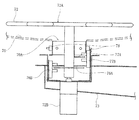
図2および図3によく示されているように、抽選装置7は、ボールBが転がるとともに当該ボールBを回収するための1つの回収孔70Aを有する抽選盤70、この抽選盤70にボールBを投入するためのバネ71Aおよびガイドレール71Bなどからなるボール投入手段、抽選盤70上において鉛直軸周りに回転するとともに、ボールBを側方から受け入れて保持可能な複数の凹部72Aを有する回転板72、回収したボールBを保持しておくための回収ボックス73、入賞穴となる凹部を光により知らせるための複数の発光体(入賞穴報知手段)74、および抽選ゲームを制御するためのマイクロコンピュータなどからなる制御部75を有して構成されている。
2 and 3, the
抽選盤70は、ボールBの転がる盤面が透明で凹曲面状に形成されており、投入されたボールBが中心部へと次第に転がるようになっている。回収孔70Aは、抽選盤70の中心部と外周部との間に形成されている。
In the
ボール投入手段は、抽選盤70の下方に設けられたバネ71Aを第1および第2回転ピン71C,71Dによって圧縮した後、その圧縮状態を解除することでプッシュロッド71Eを突き上げることにより、ガイドレール71B上にボールBを放り出す。ガイドレール71Bは、抽選盤70の下方から上方へと延び、さらに抽選盤70の外周部を概ね1周するように設けられている。ボールBは、ガイドレール71B上を転がりながら移動し、最終的には抽選盤70内に転がり落ちる。
The ball throwing means compresses the
回転板72は、抽選盤70上においてボールBの中ほどの高さに保たれており、回転用モータ72Bによって回転させられる。図4によく示されているように、回転板72の凹部72Aは、一例として番号1〜6の目印を付して等間隔に設けられており、抽選盤70の中心部へと向かうボールBがいずれかの凹部72Aに嵌るようになっている。回収孔70Aは、回転板72の回転に伴ってこれらの凹部72Aが移動する円軌道C上に設けられている。凹部72Aに保持されたボールBは、当該凹部72Aが回収孔70Aと同一箇所にあるとき、回収孔70Aに落下するようになっている。
The rotating
図4および図5によく示されているように、回転板72の軸とその周辺には、各凹部72Aの回転位置を検知するための回転位置検知手段として、第1回転子76A、第2回転子77A、第1センサ76B、第2センサ77Bが設けられている。第1回転子76Aは、各凹部72Aに対応する検知部分として複数の突出部を略60度間隔に有し、回転板72の軸と一体になって回転する。第2回転子77Aは、基準とされた例えば番号1の凹部72Aにのみ対応する検知部分として1つの突出部を有し、上記第1回転子76Aとは異なる高さ位置で回転板72の軸と一体になって回転する。第1および第2センサ76B,77Bは、たとえばフォトインタラプタからなり、それぞれ第1および第2回転子76A,77Aの突出部を検知可能に設置されている。また、回収孔70Aの下方両側には、たとえばフォトインタラプタからなり、ボールBが落下したことを検知するボール落下検知センサ78が設けられている。
As well shown in FIGS. 4 and 5, the first rotor 76 </ b> A, the second rotor 76 </ b> A, and the second rotor 76 </ b> A are provided on the shaft of the
たとえば図4に示されているように、番号1の凹部72Aが回収孔70Aに一致した状態では、第1回転子76Aの突出部が第1センサ76Bにより検知されるとともに、第2回転子77Aの突出部が第2センサ77Bにより検知される。すなわち、制御部75は、第1および第2センサ76B,77Bからの検知信号に基づき、番号1の凹部72Aが回収孔70Aに一致した状態であると認識する。その後、回転板72が時計回りに略60度回転するごとに、第1回転子76Aの突出部が第1センサ76Bにより検知される。これにより、制御部75は、番号2〜6の凹部72Aが順番に回収孔70Aに一致した状態であると認識する。さらに回転板72が回転して再び第2回転子77Aの突出部が第2センサ77Bにより検知されると、番号1の凹部72Aが回収孔70Aに一致した状態となる。このようにして制御部75は、全ての凹部72Aの回転位置を把握しているとともに、回収孔70Aと同一箇所にある凹部72Aを特定することができる。そして、制御部75は、ボール落下検知センサ78から回収孔70AにボールBが落下した旨の信号を受けると、回転板72の回転を停止させる。このとき、制御部75は、回収孔70Aと同一位置にある凹部として、たとえば番号1の凹部72Aを特定すると、当該番号1の凹部72AにボールBが保持されていたものと判断する。
For example, as shown in FIG. 4, in a state in which the
図2に示されているように、複数の発光体74は、たとえばカラーLEDからなり、抽選盤70の裏面側に配置されている。これらの発光体74は、回転板72が回転停止した状態のときに各凹部72Aと対応する位置に固定されており、これらの凹部72Aのうちのどれが入賞穴であるかを発光することによって遊技者に知らせる。
As shown in FIG. 2, the plurality of
制御部75は、表示部8に表示された3つの数字が揃うことで抽選ゲームを開始し、複数の凹部72Aのうちのどれを入賞穴とするかを所定のプログラムに基づいて決定する。入賞穴の数は、揃った数字の大きさなどに応じて異なり、1つだけの場合もあれば2つ以上の場合もある。すなわち、入賞の確率は、変動するようになっており、入賞穴は、番号1〜6の凹部72Aのうちのどれでもなりうるようになっている。たとえば番号1と番号3の凹部72Aが入賞穴に決まると、制御部75は、回転板72が回転停止中の状態において、当該番号1と番号3の凹部72Aに対応する位置にある発光体74を点灯させる。
The
次に、上記抽選装置7の動作について説明する。
Next, the operation of the
たとえば番号1の凹部72Aを入賞穴として抽選ゲームが開始されると、抽選盤70に1つのボールBが投入され、このボールBがしばらくすると、回転中の回転板72におけるいずれかの凹部72Aに保持される。なお、抽選盤70には、2以上のボールを投入するようにしてもよい。そうした場合、入賞の確率を高めることができる。
For example, when the lottery game is started with the
回転板72は、凹部72AにボールBを保持した状態で回転させられるが、ボールBを保持した凹部72Aが回収孔70Aの位置にくると、当該ボールBが凹部72Aの真下にある回収孔70Aに落下する。ボールBの落下がボール落下検知センサ78により検知されると、回転板72が回転を停止する。
The rotating
このとき、制御部75は、第1および第2センサ76B,77Bからの検知信号に基づき、回収孔70Aと同一位置にある凹部72Aの番号を特定する。たとえば回収孔70Aと同一位置にある凹部72Aについて番号1と特定したとき、この凹部72Aが入賞穴でボールBが入っていたことになることから、制御部75は、入賞した状態と判断する。入賞すると、制御部75は、多数の景品が入れられたバケット9を傾動させる。これにより、バケット9に入れられていた景品が景品落下口5やプッシャテーブル61に落下することとなり、多数の景品が払い出される。一方、回収孔70Aと同一位置にある凹部72Aがはずれ穴となる番号2〜6であるとき、制御部75は、はずれの状態と判断して抽選ゲームを終える。このような抽選ゲームは、どの凹部72AについてもボールBが入る確率
が等しく、入賞穴の数が増えると入賞の確率が上がることになるため、遊技者は、入賞の可能性が高まることを期待しつつ抽選ゲームを楽しむことができる。
At this time, the
したがって、本実施形態の抽選装置7によれば、回収孔70AにボールBが落下したことを検知した時、当該回収孔70Aと同一位置にある凹部72AがボールBの入った箇所として認識されるように構成されているため、全ての凹部72Aにつき、簡単な仕組みでボールBの入った凹部72Aを特定することができ、ひいては入賞穴の数を変えるなどして入賞の確率を容易に変更することができる。
Therefore, according to the
なお、本願発明は、上記の実施形態に限定されるものではない。たとえば抽選装置としては、景品獲得ゲーム機だけではなく、メダルゲーム機にも採用することができ、本願の趣旨を逸脱しない限り種々の設計変更が可能である。 In addition, this invention is not limited to said embodiment. For example, the lottery device can be used not only for a prize acquisition game machine but also for a medal game machine, and various design changes can be made without departing from the spirit of the present application.
7 抽選装置
70 抽選盤
70A 回収孔
71A バネ(ボール投入手段)
71B ガイドレール(ボール投入手段)
72A 凹部
72 回転板
74 発光体(入賞穴報知手段)
75 制御部(凹部特定手段、入賞穴決定手段)
76A 第1回転子(回転位置検知手段)
76B 第1センサ(回転位置検知手段)
77A 第2回転子(回転位置検知手段)
77B 第2センサ(回転位置検知手段)
78 ボール落下検知センサ(ボール落下検知手段)
B ボール
7
71B Guide rail (ball throwing means)
75 Control part (recess specifying means, winning hole determining means)
76A 1st rotor (rotation position detection means)
76B 1st sensor (rotation position detection means)
77A Second rotor (rotational position detecting means)
77B Second sensor (rotational position detecting means)
78 Ball fall detection sensor (ball fall detection means)
B ball
Claims (3)
この抽選盤にボールを投入するためのボール投入手段と、
上記抽選盤上において鉛直軸周りに回転するとともに、上記ボールを側方から受け入れて保持可能な複数の凹部を有する回転板と、
上記回転板における各凹部の回転位置を検知する回転位置検知手段と、
上記回収孔に上記ボールが落下したことを検知するボール落下検知手段と、
を備え、かつ、
上記回収孔は、上記回転板の回転に伴い上記複数の凹部が移動する円軌道上の一箇所にあって、上記ボールを保持した凹部が同一箇所にあるときに当該ボールが落下するように設けられており、
上記回収孔に上記ボールが落下したことを検知した時点で、上記各凹部について検知した回転位置に基づき、当該回収孔と同一箇所にある凹部を特定する凹部特定手段を備えている、抽選装置であって、
所定のゲームの結果に基づいて、上記複数の凹部のうち、入賞穴とする凹部の数と位置とを決定する入賞穴決定手段と、決定した入賞穴を光により知らせる入賞穴報知手段とをさらに備えることを特徴とする、抽選装置。 A lottery board having a collection hole for collecting the ball as it rolls ;
Ball throwing means for throwing balls into the lottery board ;
A rotary plate that rotates around the vertical axis on the lottery board and has a plurality of recesses that can receive and hold the ball from the side,
Rotational position detecting means for detecting the rotational position of each recess in the rotating plate;
Ball drop detection means for detecting that the ball has fallen into the recovery hole;
And having
The recovery hole is provided at one place on a circular orbit where the plurality of recesses move as the rotating plate rotates, and the balls are dropped when the recess holding the ball is at the same place. And
A lottery apparatus comprising a recess specifying means for specifying a recess located at the same location as the recovery hole based on the rotational position detected for each recess when the ball has been dropped into the recovery hole. There,
Based on the result of a predetermined game, among the plurality of recesses, there is further provided a winning hole determining unit that determines the number and position of recesses to be a winning hole, and a winning hole notifying unit that notifies the determined winning hole by light A lottery apparatus comprising: a lottery apparatus.
Priority Applications (1)
| Application Number | Priority Date | Filing Date | Title |
|---|---|---|---|
| JP2005036161A JP4528646B2 (en) | 2005-02-14 | 2005-02-14 | Lottery equipment |
Applications Claiming Priority (1)
| Application Number | Priority Date | Filing Date | Title |
|---|---|---|---|
| JP2005036161A JP4528646B2 (en) | 2005-02-14 | 2005-02-14 | Lottery equipment |
Publications (3)
| Publication Number | Publication Date |
|---|---|
| JP2006218185A JP2006218185A (en) | 2006-08-24 |
| JP2006218185A5 JP2006218185A5 (en) | 2008-03-27 |
| JP4528646B2 true JP4528646B2 (en) | 2010-08-18 |
Family
ID=36980878
Family Applications (1)
| Application Number | Title | Priority Date | Filing Date |
|---|---|---|---|
| JP2005036161A Expired - Fee Related JP4528646B2 (en) | 2005-02-14 | 2005-02-14 | Lottery equipment |
Country Status (1)
| Country | Link |
|---|---|
| JP (1) | JP4528646B2 (en) |
Families Citing this family (6)
| Publication number | Priority date | Publication date | Assignee | Title |
|---|---|---|---|---|
| JP4851975B2 (en) * | 2007-03-27 | 2012-01-11 | 株式会社バンダイナムコゲームス | Sphere transport mechanism and game apparatus |
| WO2008126599A1 (en) * | 2007-03-31 | 2008-10-23 | Kabushiki Kaisha Sega Doing Business As Sega Corporation | Game apparatus |
| JP4853835B2 (en) * | 2007-03-31 | 2012-01-11 | 株式会社セガ | Play equipment |
| JP5424554B2 (en) * | 2007-12-03 | 2014-02-26 | 株式会社カプコン | game machine |
| JP5973127B2 (en) * | 2010-11-10 | 2016-08-23 | 株式会社ユニバーサルエンターテインメント | Gaming machine |
| GB2626034A (en) * | 2023-01-09 | 2024-07-10 | Electrocoin Automatics Ltd | Entertainment Machine |
Citations (6)
| Publication number | Priority date | Publication date | Assignee | Title |
|---|---|---|---|---|
| JPH08229190A (en) * | 1995-02-28 | 1996-09-10 | Taihei Giken Kogyo Kk | Win judging device of roulette game machine |
| JPH08229191A (en) * | 1995-02-28 | 1996-09-10 | Taihei Giken Kogyo Kk | Roulette game machine |
| JPH0984955A (en) * | 1995-02-21 | 1997-03-31 | Taihei Giken Kogyo Kk | Game machine |
| JP2002210221A (en) * | 2001-01-22 | 2002-07-30 | Konami Co Ltd | Lottery carrying device and game machine provided with the same |
| JP2004248690A (en) * | 2003-02-17 | 2004-09-09 | Konami Co Ltd | Lottery device and game machine |
| JP2006081768A (en) * | 2004-09-16 | 2006-03-30 | Konami Co Ltd | Pusher game machine and game machine |
-
2005
- 2005-02-14 JP JP2005036161A patent/JP4528646B2/en not_active Expired - Fee Related
Patent Citations (6)
| Publication number | Priority date | Publication date | Assignee | Title |
|---|---|---|---|---|
| JPH0984955A (en) * | 1995-02-21 | 1997-03-31 | Taihei Giken Kogyo Kk | Game machine |
| JPH08229190A (en) * | 1995-02-28 | 1996-09-10 | Taihei Giken Kogyo Kk | Win judging device of roulette game machine |
| JPH08229191A (en) * | 1995-02-28 | 1996-09-10 | Taihei Giken Kogyo Kk | Roulette game machine |
| JP2002210221A (en) * | 2001-01-22 | 2002-07-30 | Konami Co Ltd | Lottery carrying device and game machine provided with the same |
| JP2004248690A (en) * | 2003-02-17 | 2004-09-09 | Konami Co Ltd | Lottery device and game machine |
| JP2006081768A (en) * | 2004-09-16 | 2006-03-30 | Konami Co Ltd | Pusher game machine and game machine |
Also Published As
| Publication number | Publication date |
|---|---|
| JP2006218185A (en) | 2006-08-24 |
Similar Documents
| Publication | Publication Date | Title |
|---|---|---|
| KR100732081B1 (en) | Lottery device and game player | |
| US6083105A (en) | Computerized roulette playing apparatus for a single player | |
| JP3201740B2 (en) | Ball game machine | |
| JP4528646B2 (en) | Lottery equipment | |
| JP4302699B2 (en) | Lottery device and gaming machine using the same | |
| JP2006218185A5 (en) | ||
| JP3499217B2 (en) | Lottery transfer device and gaming machine equipped with the same | |
| JP3999066B2 (en) | Ball game machine | |
| JP4772296B2 (en) | game machine | |
| JP5485556B2 (en) | Lottery equipment | |
| JP2008049071A (en) | Token counter | |
| JP2005329116A (en) | Game machine | |
| JP5277484B2 (en) | Bullet ball machine | |
| JP4896382B2 (en) | Lottery equipment | |
| JP2566181B2 (en) | A game machine using a pachinko ball | |
| JP5148907B2 (en) | Game machine | |
| JP5097645B2 (en) | Medal throwing device and medal game machine using the same | |
| JP6342469B2 (en) | game machine | |
| JP2006223330A (en) | Game machine | |
| JP2011240045A (en) | Game device | |
| JP4245497B2 (en) | Pachinko machine | |
| JP4154354B2 (en) | Pachinko machine | |
| JP4583475B2 (en) | Pachinko machine | |
| GB2363733A (en) | Roulette apparatus with display | |
| GB2348822A (en) | An automated roulette wheel for use with a plurality of balls |
Legal Events
| Date | Code | Title | Description |
|---|---|---|---|
| A521 | Written amendment |
Free format text: JAPANESE INTERMEDIATE CODE: A523 Effective date: 20080207 |
|
| A621 | Written request for application examination |
Free format text: JAPANESE INTERMEDIATE CODE: A621 Effective date: 20080207 |
|
| A977 | Report on retrieval |
Free format text: JAPANESE INTERMEDIATE CODE: A971007 Effective date: 20091201 |
|
| A131 | Notification of reasons for refusal |
Free format text: JAPANESE INTERMEDIATE CODE: A131 Effective date: 20091222 |
|
| A521 | Written amendment |
Free format text: JAPANESE INTERMEDIATE CODE: A523 Effective date: 20100203 |
|
| A131 | Notification of reasons for refusal |
Free format text: JAPANESE INTERMEDIATE CODE: A131 Effective date: 20100302 |
|
| A521 | Written amendment |
Free format text: JAPANESE INTERMEDIATE CODE: A523 Effective date: 20100427 |
|
| TRDD | Decision of grant or rejection written | ||
| A01 | Written decision to grant a patent or to grant a registration (utility model) |
Free format text: JAPANESE INTERMEDIATE CODE: A01 Effective date: 20100525 |
|
| A01 | Written decision to grant a patent or to grant a registration (utility model) |
Free format text: JAPANESE INTERMEDIATE CODE: A01 |
|
| A61 | First payment of annual fees (during grant procedure) |
Free format text: JAPANESE INTERMEDIATE CODE: A61 Effective date: 20100607 |
|
| FPAY | Renewal fee payment (event date is renewal date of database) |
Free format text: PAYMENT UNTIL: 20130611 Year of fee payment: 3 |
|
| R150 | Certificate of patent or registration of utility model |
Ref document number: 4528646 Country of ref document: JP Free format text: JAPANESE INTERMEDIATE CODE: R150 Free format text: JAPANESE INTERMEDIATE CODE: R150 |
|
| R250 | Receipt of annual fees |
Free format text: JAPANESE INTERMEDIATE CODE: R250 |
|
| R250 | Receipt of annual fees |
Free format text: JAPANESE INTERMEDIATE CODE: R250 |
|
| R250 | Receipt of annual fees |
Free format text: JAPANESE INTERMEDIATE CODE: R250 |
|
| LAPS | Cancellation because of no payment of annual fees |