JP4527619B2 - Preconcentration interface for connecting liquid chromatography to capillary electrophoresis - Google Patents
Preconcentration interface for connecting liquid chromatography to capillary electrophoresis Download PDFInfo
- Publication number
- JP4527619B2 JP4527619B2 JP2005193598A JP2005193598A JP4527619B2 JP 4527619 B2 JP4527619 B2 JP 4527619B2 JP 2005193598 A JP2005193598 A JP 2005193598A JP 2005193598 A JP2005193598 A JP 2005193598A JP 4527619 B2 JP4527619 B2 JP 4527619B2
- Authority
- JP
- Japan
- Prior art keywords
- separation
- cze
- fraction
- electrodes
- sample
- Prior art date
- Legal status (The legal status is an assumption and is not a legal conclusion. Google has not performed a legal analysis and makes no representation as to the accuracy of the status listed.)
- Expired - Fee Related
Links
Images

Classifications
-
- G—PHYSICS
- G01—MEASURING; TESTING
- G01N—INVESTIGATING OR ANALYSING MATERIALS BY DETERMINING THEIR CHEMICAL OR PHYSICAL PROPERTIES
- G01N27/00—Investigating or analysing materials by the use of electric, electrochemical, or magnetic means
- G01N27/26—Investigating or analysing materials by the use of electric, electrochemical, or magnetic means by investigating electrochemical variables; by using electrolysis or electrophoresis
- G01N27/416—Systems
- G01N27/447—Systems using electrophoresis
- G01N27/44756—Apparatus specially adapted therefor
-
- G—PHYSICS
- G01—MEASURING; TESTING
- G01N—INVESTIGATING OR ANALYSING MATERIALS BY DETERMINING THEIR CHEMICAL OR PHYSICAL PROPERTIES
- G01N30/00—Investigating or analysing materials by separation into components using adsorption, absorption or similar phenomena or using ion-exchange, e.g. chromatography or field flow fractionation
- G01N30/02—Column chromatography
- G01N30/26—Conditioning of the fluid carrier; Flow patterns
- G01N30/38—Flow patterns
- G01N30/46—Flow patterns using more than one column
- G01N30/461—Flow patterns using more than one column with serial coupling of separation columns
- G01N30/463—Flow patterns using more than one column with serial coupling of separation columns for multidimensional chromatography
-
- G—PHYSICS
- G01—MEASURING; TESTING
- G01N—INVESTIGATING OR ANALYSING MATERIALS BY DETERMINING THEIR CHEMICAL OR PHYSICAL PROPERTIES
- G01N30/00—Investigating or analysing materials by separation into components using adsorption, absorption or similar phenomena or using ion-exchange, e.g. chromatography or field flow fractionation
- G01N30/02—Column chromatography
- G01N30/84—Preparation of the fraction to be distributed
-
- G—PHYSICS
- G01—MEASURING; TESTING
- G01N—INVESTIGATING OR ANALYSING MATERIALS BY DETERMINING THEIR CHEMICAL OR PHYSICAL PROPERTIES
- G01N30/00—Investigating or analysing materials by separation into components using adsorption, absorption or similar phenomena or using ion-exchange, e.g. chromatography or field flow fractionation
- G01N30/02—Column chromatography
- G01N30/88—Integrated analysis systems specially adapted therefor, not covered by a single one of the groups G01N30/04 - G01N30/86
- G01N2030/8809—Integrated analysis systems specially adapted therefor, not covered by a single one of the groups G01N30/04 - G01N30/86 analysis specially adapted for the sample
- G01N2030/8813—Integrated analysis systems specially adapted therefor, not covered by a single one of the groups G01N30/04 - G01N30/86 analysis specially adapted for the sample biological materials
- G01N2030/8831—Integrated analysis systems specially adapted therefor, not covered by a single one of the groups G01N30/04 - G01N30/86 analysis specially adapted for the sample biological materials involving peptides or proteins
-
- G—PHYSICS
- G01—MEASURING; TESTING
- G01N—INVESTIGATING OR ANALYSING MATERIALS BY DETERMINING THEIR CHEMICAL OR PHYSICAL PROPERTIES
- G01N30/00—Investigating or analysing materials by separation into components using adsorption, absorption or similar phenomena or using ion-exchange, e.g. chromatography or field flow fractionation
- G01N30/02—Column chromatography
- G01N30/26—Conditioning of the fluid carrier; Flow patterns
- G01N30/38—Flow patterns
- G01N30/46—Flow patterns using more than one column
- G01N30/461—Flow patterns using more than one column with serial coupling of separation columns
- G01N30/465—Flow patterns using more than one column with serial coupling of separation columns with specially adapted interfaces between the columns
Abstract
Description
本発明は、例えばペプチドの複雑な混合物の液体クロマトグラフィーによる二次元分離用装置および方法に関する。特に、本発明は、質量分析計に直接噴霧するキャピラリー電気泳動(CE)の前段にある逆相液体クロマトグラフィー(RPLC)に関する。 The present invention relates to an apparatus and a method for two-dimensional separation, for example by liquid chromatography of complex mixtures of peptides. In particular, the present invention relates to reverse phase liquid chromatography (RPLC) upstream of capillary electrophoresis (CE) spraying directly onto a mass spectrometer.
2Dポリアクリルアミドゲル電気泳動(PAGE)にとって重大な制約の一部が2D LCによって克服されることが判明したことから、二次元液体クロマトグラフィー法/質量分析法(LC/MS)は、プロテオミクス研究および応用において重要な役割を果たし始めている。詳細な総説については[文献1]を参照されたい。主な利点は、自動化、分析時間の短縮、高感度化、および再現性の向上である。希釈サンプルをカラム上で濃縮することができ、より迅速な同定および定量が可能となるUV、LIFおよび特にMSのような様々な検出システムと接続することができる。 Two-dimensional liquid chromatography / mass spectrometry (LC / MS) has been found to be a proteomics research and study because it has been found that 2D LC overcomes some of the critical limitations for 2D polyacrylamide gel electrophoresis (PAGE). Has begun to play an important role in application. See [Reference 1] for a detailed review. The main advantages are automation, reduced analysis time, higher sensitivity, and improved reproducibility. Diluted samples can be concentrated on the column and can be connected to various detection systems such as UV, LIF and especially MS that allow for faster identification and quantification.
ペプチドレベルでの分析は、いくつかの理由のために好ましいが、主として、ペプチドが初期に多種多様な溶媒により容易に溶解し、親タンパク質よりも分離が容易であるために好ましい。しかし、ペプチドを扱う際には、溶解しなければならない種の数が増加する欠点がある。したがって、分離中にはより高い分解能が必要とされ、利用可能な予備分画技術を使用することがより重要になる。 Analysis at the peptide level is preferred for several reasons, but is primarily preferred because the peptide is initially readily soluble in a wide variety of solvents and is easier to separate than the parent protein. However, when dealing with peptides, there is the disadvantage that the number of species that must be dissolved increases. Therefore, higher resolution is required during separation and it becomes more important to use available pre-fractionation techniques.
オンライン2D-LCシステムの基本的な考え方は、1次元目に徐々に分離し、2次元目に迅速に分離することである。試料採取速度を落とさずに、または1次元目を減速せずに、2次元目における高分解能要件を満たすためには、少なくとも2本の2次元目用カラムを並行して溶出させる必要がある。報告が最も多く、最も多く適用され商用化された2D-LC手法は、イオン交換クロマトグラフィー(IEX)にRPLCが後続するものである。これら2つの技術は全く異なり、最初の技術は電荷分離機構(塩溶出ステップ)に基づいており、第2の技術は疎水性(有機溶媒による勾配溶出)に基づいている。IEXは、MSとは両立せず、したがって、1次元目に使用される。IEXから得られる画分は、1本または2本の平行濃縮カラムで捕捉され洗浄された後に、一般にESIインターフェースを介してMSに直接接続することができるRPLC(1本または2本の平行カラム)による第2の分離にかけられる。この手法の制約は、全体の分析時間が依然として長いということである。理論的に、利点が最も多い組合せの1つは、LCとそれに後続するキャピラリーゾーン電気泳動(CZE)であるが、これまで、この特定の組合せは1つも商用化されておらず、文献にもほとんど見当たらない。これら2つの技術も異なり、互換性があり、質量分析法と両立する。これらはどちらも高分解能であり、全ピーク容量が増加し、組み合わせると、他のいかなる2D組合せよりも迅速になり得る。CZE分離を実施することができる速度は、第1のカラムから第2のカラムへの溶出物の連続採取を可能とし、RPLC分離を実施するのに要する時間である1次元目を終了するのに要する時間内に2D分析を終了することができる。この方策の進展を歴史的に遅らせてき決定的な問題は、おそらく、これら2つの分離技術のインターフェースであろう。興味深い考え方は、必ずしもこの特定の組合せを意図したものではないが、ある程度有効な解決法である。少数の別法が、機械弁に基づく特許文献(米国特許第5,240,577号A)、およびフローゲート(米国特許第5,496,460号A)または光学的ゲート概念(米国特許第5,269,900号A)に基づく特許文献に記載されている。米国特許第6,192,768号B1に記載されているとおり、例えば、CE用キャピラリーへの連続流から得られる規定体積の液滴をいくつかの手段のうちの1つによって分配することに基づく別の概念を使用することもできる。例えばEOF(電気浸透流)制御に基づく別の概念が、米国特許第6,475,363号B1に記載されている。しかし、すべての場合において、個々の制約に加えて、溶出物の大部分が情報損失のリスクをかかえたまま廃棄され、感度が確実には改善されないという共通欠点が依然として残っている。 The basic idea of an online 2D-LC system is to gradually separate in the first dimension and quickly in the second dimension. In order to meet the high resolution requirements in the second dimension without slowing the sampling rate or slowing down the first dimension, it is necessary to elute at least two second dimension columns in parallel. The most reported and most widely applied and commercialized 2D-LC technique is ion exchange chromatography (IEX) followed by RPLC. These two techniques are quite different: the first technique is based on a charge separation mechanism (salt elution step) and the second technique is based on hydrophobicity (gradient elution with an organic solvent). IEX is not compatible with MS and is therefore used in the first dimension. RPLC (one or two parallel columns) that can be directly connected to the MS, typically via an ESI interface, after the fractions obtained from IEX are captured and washed by one or two parallel concentration columns Subjected to a second separation by. The limitation of this approach is that the overall analysis time is still long. Theoretically, one of the most advantageous combinations is LC followed by capillary zone electrophoresis (CZE), but to date, none of this particular combination has been commercialized and has been published in the literature. I can hardly find it. These two technologies are also different, compatible, and compatible with mass spectrometry. Both of these are high resolution, increasing the total peak capacity, and when combined can be faster than any other 2D combination. The rate at which CZE separation can be performed allows for continuous collection of eluate from the first column to the second column, to complete the first dimension, which is the time required to perform the RPLC separation. The 2D analysis can be completed within the time required. Perhaps the decisive issue that has historically slowed the development of this strategy is the interface between these two separation technologies. An interesting idea is not necessarily intended for this particular combination, but is a somewhat effective solution. A few alternatives are in the patent literature based on mechanical valves (US Pat.No. 5,240,577A) and on the basis of flow gates (US Pat.No. 5,496,460A) or optical gate concepts (US Pat. Are listed. As described in U.S. Pat.No. 6,192,768 B1, for example, another concept based on dispensing a defined volume of droplets obtained from a continuous flow into a CE capillary by one of several means. It can also be used. Another concept, for example based on EOF (electroosmotic flow) control, is described in US Pat. No. 6,475,363 B1. However, in all cases, in addition to the individual constraints, the common drawback remains that the majority of the eluate is discarded with the risk of information loss and the sensitivity is not reliably improved.
したがって、本発明の目的は、第1の分離とそれに続く分離ステップとのインターフェース段階における制約を、提案された考え方に関して報告されている欠点を伴わずに克服する解決法を提案することである。 The object of the present invention is therefore to propose a solution that overcomes the limitations in the interface phase between the first separation and the subsequent separation step, without the reported drawbacks of the proposed idea.
特に、本発明の一目的は、RPLC分離とそれに続くCE分離とのインターフェースを提案することである。 In particular, one object of the present invention is to propose an interface between RPLC separation and subsequent CE separation.
本発明は、請求項1または請求項10の文言によって、それぞれ装置および方法を提案する。
The present invention proposes an apparatus and a method, respectively, according to the language of claim 1 or
本発明は、主として、第1のカラムから第2のカラムへの溶出物を採取することにより、連続流からの混入なしに、注入画分のキャピラリーゾーン電気泳動分離に対して十分な時間が得られる方法を開示する。第1のカラムから溶出する画分は、2個の電極によって画定される1個の短いセグメント中で、第2の分離と他のもう1つとの間にある次の注入の前に濃縮される。これによって、1次元目の分離において含まれる全情報が保存されるだけでなく、2次元目における感度および分解能が大きく増加する。キャピラリー電気泳動法におけるカラム上での予備濃縮は新規ではない[文献10〜11]が、これら公知の方法は、例えば等速電気泳動および電場増幅のための不連続な緩衝システム、または脱着のための移動相もしくは緩衝剤の変更も一般に必要とする吸着材料もしくは結合材料の使用を必要とする。界面動電捕捉も、最近、米国特許第6,428,666号B1に報告されており、タンパク質は、印加された電場下でシリカ粒子上に捕捉され、電場の非存在下で圧力をかけて溶出される。ごく最近、本発明とは無関係に並行して、流体力と電気力の平衡に基づく流体電気捕捉(fluidic electrocapture)装置が開発され、発表された[文献11〜12]。しかし、これは、例えばマトリックス支援レーザー脱離イオン化質量分析法(MALDI-MS)前のペプチドおよびタンパク質の1段階試料精製、またはキャピラリー電気泳動法による一次元オフライン分析前の予備濃縮用であり、実際、本発明のインターフェースが基づく原理を証明するのに役立つだけである。 The present invention mainly collects the eluate from the first column to the second column, thereby obtaining sufficient time for capillary zone electrophoresis separation of the injected fraction without mixing from the continuous flow. Disclosed method. The fraction eluting from the first column is concentrated in one short segment defined by two electrodes before the next injection between the second separation and the other . This not only preserves all the information contained in the first dimension separation, but also greatly increases the sensitivity and resolution in the second dimension. Although preconcentration on a column in capillary electrophoresis is not new [10-11], these known methods are for example a discontinuous buffer system for isotachophoresis and electric field amplification, or for desorption. Changing the mobile phase or buffering agent generally requires the use of adsorbent or binding materials that are generally required. Electrokinetic trapping has also been recently reported in US Pat. No. 6,428,666 B1, where proteins are trapped on silica particles under an applied electric field and eluted under pressure in the absence of an electric field. Very recently, in parallel with the present invention, a fluid electrocapture device based on the balance of fluid and electrical forces has been developed and published [11-12]. However, this is for example for one-step sample purification of peptides and proteins before matrix-assisted laser desorption / ionization mass spectrometry (MALDI-MS), or for preconcentration before one-dimensional offline analysis by capillary electrophoresis. It only serves to prove the principle on which the interface of the present invention is based.
本発明による方法においては、例えばCEなどの第2のステップの分離中のEOF値、またはあらゆる原因、例えば閉塞もしくは気泡によるシステム内の圧力降下に拘わらず、流れは決して止められず、例えばRPLCなどの第1の分離を実施する速度(例えば、100 nl/min)で一定に保たれる。これは、例えば、Agilent TechnologiesおよびDionex LC Packingsによって商用化されたナノポンプ技術の最近の進歩のお陰で可能になり得る。この効果によって、MS-分析のための安定なエレクトロスプレーも確実に行うことができる。 In the method according to the invention, the flow is never stopped regardless of the EOF value during the separation of the second step, e.g. CE, or the pressure drop in the system due to any cause, e.g. occlusion or bubbles, e.g. RPLC Is kept constant at the rate at which the first separation is performed (eg, 100 nl / min). This may be possible, for example, thanks to recent advances in nanopump technology commercialized by Agilent Technologies and Dionex LC Packings. This effect ensures a stable electrospray for MS-analysis.
したがって、具体的には、本発明は、マイクロRPLCの代わりのナノRPLCとCZEの併用に関する。マイクロRPLCは、通常、内径が0.3〜3 mmであり、典型的な流量が1〜500μl/minであるカラムに基づいている。一方、ナノRPLCは、内径が75〜100ミクロンであり、典型的な流量が0.1〜1μl/min(100〜1000 nl/min)であるカラムに基づいている。その結果、LCに適用される流量(<200 nl/min)は、今や第1のカラムと完全に連結され、他方ではESIインターフェースを介してMSに接続されるCZEの分離速度と適合する。換言すれば、RPLCからの全溶出物は、バルブもデッドボリュームもなくCZEチャネルをそのまま流れ、廃棄されるものがなく、希釈もされない。 Therefore, specifically, the present invention relates to a combination of nano RPLC and CZE instead of micro RPLC. Micro-RPLC is usually based on columns with an internal diameter of 0.3-3 mm and a typical flow rate of 1-500 μl / min. Nano RPLC, on the other hand, is based on columns with an internal diameter of 75-100 microns and typical flow rates of 0.1-1 μl / min (100-1000 nl / min). As a result, the flow rate applied to the LC (<200 nl / min) now matches the separation rate of CZE, which is now fully connected to the first column and on the other hand connected to the MS via the ESI interface. In other words, the total effluent from the RPLC flows through the CZE channel without any valve or dead volume and is not discarded or diluted.
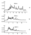
RPLC分離とCZE分離の両方、および質量分析法とも適合する条件を見出すことができるので、CZE分析前に緩衝剤を変更する必要はない。このことはいくつかの実験によって証明され、20%アセトニトリル(ACN)/0.4%トリエチルアミン(TEA)/0.3%トリフルオロ酢酸(TFA)からなる緩衝剤中のペプチド混合物(30種のペプチドを産生するIgGのトリプシン消化産物)のCZEによって得られる分解能は(図1c)、塩含量が高く、尿素などの添加剤が存在するために、MSおよびRPLCとは適合しない最適で特徴の明らかな緩衝剤系において得られる分解能と同等である(図1aおよび1b)。図1aによれば、緩衝剤1は、イミノ二酢酸(IDA)50mM、ヒドロキシエチルセルロース(HEC)0.5%、および7Mウレアからなる。緩衝剤2は、50mM IDA/10%トリフルオロエタノール(TFE)/0.5%HECからなる。図1cのグラフに、本発明から得られる2次元目での分離を示す。
Conditions that are compatible with both RPLC and CZE separations and mass spectrometry can be found, so there is no need to change the buffer prior to CZE analysis. This has been proved by several experiments, a mixture of peptides in a buffer consisting of 20% acetonitrile (ACN) /0.4% triethylamine (TEA) /0.3% trifluoroacetic acid (TFA) (an IgG producing 30 peptides). The resolution obtained by CZE (Figure 1c) is in an optimally characterized buffer system that is not compatible with MS and RPLC due to the high salt content and the presence of additives such as urea. It is equivalent to the resolution obtained (FIGS. 1a and 1b). According to FIG. 1a, buffer 1 consists of iminodiacetic acid (IDA) 50 mM, hydroxyethylcellulose (HEC) 0.5%, and 7M urea.
1次元目の分離としてキャピラリー通電クロマトグラフィー(CEC)を使用することもできる。 Capillary electrochromatography (CEC) can also be used for the first dimension separation.
内部電極を使用するときに起こる電気分解および気泡形成の問題は、[文献12〜13]に記載の塩橋電極または導電膜を代わりに組み込むことによって防止することができる。本発明の一部として、可能な実施例によれば、例えば2〜3μm程度の極めて狭い開口部によってCEチャネルと接触しているマイクロチャネルからなり、例えばナフィオン(登録商標)ポリマーまたは他のイオン選択性材料が充填された2個の微小電極が予備濃縮に使用される。ナフィオン(登録商標)は、スルホン酸基がその中に分散された基本的にテフロン(登録商標)であり、水に対して極めて高い親和性を有する。各スルホン酸は、最高13個の水分子を結合することができ、水和の水として吸引される。各スルホン酸基が相互に連結することによって、ナフィオン(登録商標)を通る水、したがってプロトンの移動が極めて速くなる。実際、ナフィオン(登録商標)の主な応用例の1つは、ポリマー電極燃料電池におけるプロトン交換膜である。最終的に、他の小さな陽イオンは通過することができるが、ペプチドサイズの分析物は通過することができない。これによって、クロマトグラフィーピークにおいて共溶出するペプチドを、流体力学的流れの掃流力(dragging force)に打ち勝つのに十分な強度の電圧をペプチドの電荷(この場合、正)と反対の極性で印加することによって、これらの電極の2個に挟まれた短い区間内で濃縮することが可能になる。CEへの注入は、2個の電極間の電位差をなくし、第2の電極を通過し濃縮区間から流出するのに必要な時間、圧縮試料プラグが流れにより運ばれることによって実施される。分離のために第2の電極とカソードの間に印加される電圧は常にオンであり、2個の濃縮電極間に印加される電圧は注入中のみ遮断される。 Electrolysis and bubble formation problems that occur when using internal electrodes can be prevented by incorporating the salt bridge electrodes or conductive films described in [Refs. 12-13] instead. As part of the present invention, according to a possible embodiment, it consists of a microchannel in contact with the CE channel by a very narrow opening, e.g. on the order of 2 to 3 μm, e.g. Two microelectrodes filled with a functional material are used for preconcentration. Nafion® is basically Teflon® with sulfonic acid groups dispersed in it and has a very high affinity for water. Each sulfonic acid can bind up to 13 water molecules and is aspirated as hydrated water. By linking each sulfonic acid group together, the movement of water and thus protons through Nafion® is very fast. Indeed, one of the main applications of Nafion® is in proton exchange membranes in polymer electrode fuel cells. Eventually, other small cations can pass through, but peptide size analytes cannot pass through. This allows a peptide that co-elutes at the chromatographic peak to be applied with a polarity that is strong enough to overcome the dragging force of the hydrodynamic flow, with a polarity opposite to the peptide charge (in this case, positive). By doing so, it becomes possible to concentrate in a short section sandwiched between two of these electrodes. The injection into the CE is performed by eliminating the potential difference between the two electrodes and carrying the compressed sample plug by flow for the time required to pass through the second electrode and out of the concentration zone. The voltage applied between the second electrode and the cathode for separation is always on, and the voltage applied between the two concentration electrodes is cut off only during injection.
本発明を、例えば、本発明の略図である図2を参照してさらに詳細に述べる。 The present invention will be described in further detail, for example, with reference to FIG. 2, which is a schematic representation of the present invention.
例えばRPLCカラムなどの第1の分離装置の後に、分離された試料または画分は、それぞれ、中間区間11内に導入される。中間区間は例えばCE分離チャネルなどの前方の別の分離装置3と繋がっている。試料は、分離チャネル3を出ると、質量分析装置5に進み、注入または噴霧される。
After a first separation device, for example an RPLC column, the separated samples or fractions are each introduced into the intermediate section 11. The intermediate section is connected to another separation device 3 in front such as a CE separation channel. As the sample exits the separation channel 3, it proceeds to the
中間区間11は、いわゆる予備濃縮区間13が画定される距離で配列された2個の電極E1とE2を含む。
The intermediate section 11 includes two electrodes E1 and E2 arranged at a distance where a so-called
RPLCカラム1から流出した画分は、まず、画分中の分析物が電極E2を通過できないような電位差に2個の電極E1とE2を維持することによって、予備濃縮区間13において予備濃縮される。それぞれある時間または予備濃縮時間が経過した後に、予備濃縮された分析物画分が電極E2を通過し、例えばCE分離チャネルである第2の分離装置3に流入するように、電極をオフにし、または極性を反転させる。電極E0とE1によって画定される予備・予備濃縮(pre-preconcentration)区間を導入することによって、RPLC装置から流出したさらに別の成分が、CE区間3への注入が終了する前に予備濃縮区間13に注入するのをさらに防止することができる。
The fraction flowing out of RPLC column 1 is first pre-concentrated in
図2が本発明による設計の一例に過ぎないことは言うまでもない。さらに別の予備濃縮区間を画定するために、さらに別の電極を配置できることは言うまでもない。 It goes without saying that FIG. 2 is only an example of a design according to the invention. It goes without saying that further electrodes can be arranged to define further preconcentration zones.
本発明の装置の大きな利点は、流れ自体は中断されず、あらゆる溶媒または輸送液の流れが一定であることである。また、溶出物が情報損失のリスクをかかえたまま廃棄されることはない。 The great advantage of the device of the present invention is that the flow itself is not interrupted and the flow of any solvent or transport liquid is constant. In addition, the eluate is not discarded with the risk of information loss.
本発明の方法の寸法および値、流量、分析電圧および時間の見当をつけるために、例として以下の計算を行うことができる。 In order to ascertain the dimensions and values, flow rates, analysis voltages and times of the method of the present invention, the following calculations can be made by way of example.
RPLCとして、長さ15cm×ID(内径)75μmのC18カラムを使用することができ、勾配溶出の流量を100 nl/minとすることができる。RPLC溶出物が流れるCEチャネルを50μm IDとすることができ、電気泳動が起こる有効長を5 cmとすることができる。CE分離前の予備濃縮区間は1 mm長である。 As the RPLC, a C18 column having a length of 15 cm × ID (inner diameter) of 75 μm can be used, and the flow rate of gradient elution can be set to 100 nl / min. The CE channel through which the RPLC eluate flows can be 50 μm ID, and the effective length at which electrophoresis occurs can be 5 cm. The preconcentration zone before CE separation is 1 mm long.
この系においては、線流速(vf)は0.085 cm/sである。上記緩衝系における分離から計算されるペプチドの電気泳動移動度(μ)は、一般に、1.0×10-4 cm2 sec-1 V-1〜1.6×10⁻⁴ cm2 sec-1 V-1である。式ve = μE(式中、veは電気泳動速度であり、Eは電場である)から、2kV/cm、すなわち10 kV/5 cmの電場によって、veは0.2 cm/s〜0.36 cm/sになる。したがって、vfとveの合計である全速度(vtot)は、0.285 cm/sec〜0.445 cm/secの範囲になり、検出時間は第1のピークの10秒〜最終ピークの18秒の間になる。一方、クロマトグラフィーのピークの場合には、推定30秒が妥当である。これは、電気泳動をかける時間が十分にあり、次のクロマトグラフィーのピークが次の注入の前に濃縮されることを意味する。電圧が高いためにジュール効果によって熱が発生し、分解能が減少することは、液体系のイオン強度が低く、チャネル寸法が小さく、流速により新しい液体が常時運び込まれるために大きな問題ではない。 In this system, the linear flow velocity (v f ) is 0.085 cm / s. The electrophoretic mobility (μ) of the peptide calculated from the separation in the buffer system is generally 1.0 × 10 −4 cm 2 sec −1 V −1 to 1.6 × 10 −4 cm 2 sec −1 V −1 . is there. From the equation v e = μE, where v e is the electrophoretic velocity and E is the electric field, from an electric field of 2 kV / cm, i.e. 10 kV / 5 cm, v e is 0.2 cm / s to 0.36 cm / s. Therefore, the total velocity (v tot ), which is the sum of v f and v e , ranges from 0.285 cm / sec to 0.445 cm / sec, and the detection time is from 10 seconds for the first peak to 18 seconds for the final peak. Between. On the other hand, an estimated 30 seconds is reasonable for chromatographic peaks. This means that there is ample time for electrophoresis and the next chromatographic peak is concentrated before the next injection. The fact that heat is generated by the Joule effect due to the high voltage and the resolution is reduced is not a big problem because the ionic strength of the liquid system is low, the channel size is small, and a new liquid is always carried by the flow velocity.
捕捉電場の値は、vfと最低ペプチド移動度の比、すなわち850 V/cm、85 V/mmよりも大きくなければならない。この電場をゼロにして注入を可能にする時間は1.2秒である。 The value of the trapping electric field must be greater than the ratio of v f to the lowest peptide mobility, ie 850 V / cm, 85 V / mm. The time to allow injection with this electric field zero is 1.2 seconds.
極めて高い濃縮係数を実現することができる。 An extremely high concentration factor can be realized.
このインターフェースの別の種類においては、やはり1 mm×50μmの濃縮区間は、陽イオン交換材料で充填されており、この区間における電場の非存在下で試料が蓄積される。次いで、流れと同じ方向に極性を有する十分な電圧を印加することによって試料が脱着される。この場合に必要な電場は、使用する最終固定相に左右されるので推定されないが、pHを低くし、TFAなどのイオン対形成剤を存在させることによって、この電場を低くすべきである。上述の実施例および図2の略図は、本発明をさらに詳細に説明するのに使用され、本発明がこの実施例および図2の略図に何ら限定されないことは言うまでもない。 In another type of this interface, the 1 mm × 50 μm enrichment section is again filled with cation exchange material, and the sample is accumulated in the absence of an electric field in this section. The sample is then desorbed by applying a sufficient voltage with polarity in the same direction as the flow. The electric field required in this case is not estimated as it depends on the final stationary phase used, but should be lowered by lowering the pH and the presence of an ion-pairing agent such as TFA. The above-described embodiment and the schematic diagram of FIG. 2 are used to describe the present invention in more detail, and it goes without saying that the present invention is not limited to this embodiment and the schematic diagram of FIG.
文献リスト
参考文献
[1]. Sarka Beranova-Giorgianni. Proteon analysis by two-dimensional gel electrophoresis and mass spectrometry: strengths and limitations. Trends in Anal. Chem. 2003、22、273〜81。
Reference list
[1]. Sarka Beranova-Giorgianni. Proteon analysis by two-dimensional gel electrophoresis and mass spectrometry: strengths and limitations. Trends in Anal. Chem. 2003, 22, 273-81.
[2]. Opiteck等 Comprehensive two-dimensional high-performance liquid chromatography for the isolation of overexpressed proteins and protein mapping. Anal. Bioch. 1998、258、349〜61。 [2]. Opiteck et al. Comprehensive two-dimensional high-performance liquid chromatography for the isolation of overexpressed proteins and protein mapping. Anal. Bioch. 1998, 258, 349-61.
[3]. Opiteck等 Comprehensive on-line LC/LC/MS of proteins. Anal. Chem. 1997、69、1518〜24。 [3]. Opiteck et al. Comprehensive on-line LC / LC / MS of proteins. Anal. Chem. 1997, 69, 1518-24.
[4]. Washburn等 Large-scale analysis of the yeast proteome by multidimensional protein identification technology. Nature Biotech. 2001、19、242〜47。 [4]. Washburn et al. Large-scale analysis of the yeast proteome by multidimensional protein identification technology. Nature Biotech. 2001, 19, 242-47.
[5]. Wolters等 An automated multidimensional protein identification technology for shotgun proteomics. Anal. Chem. 2001、73、5683〜90。 [5]. Wolters et al. An automated multidimensional protein identification technology for shotgun proteomics. Anal. Chem. 2001, 73, 5683-90.
[6]. Wagner等 An automated on-line multidimensional HPLC system for protein and peptide mapping with integrated sample preparation. Anal. Chem. 2002、74、809〜820。 [6]. Wagner et al. An automated on-line multidimensional HPLC system for protein and peptide mapping with integrated sample preparation. Anal. Chem. 2002, 74, 809-820.
[7]. Moore等 Rapid comprehensive two-dimensional separations of peptides via RPLC-optically gated capillary zone electrophoresis. Anal. Chem. 1995、67、3448〜55。 [7]. Moore et al. Rapid comprehensive two-dimensional separations of peptides via RPLC-optically gated capillary zone electrophoresis. Anal. Chem. 1995, 67, 3448-55.
[8]. Lewis等 Comprehensive on-line RPLC-CZE-MS of peptides. J. Am. Soc. Mass Spectrom. 1997、8、495〜500。 [8]. Lewis et al. Comprehensive on-line RPLC-CZE-MS of peptides. J. Am. Soc. Mass Spectrom. 1997, 8, 495-500.
[9]. Han等 Quantitative profiling of differentiation-induced microsomal proteins using isotope-coded affinity tags and mass spectrometry. Nature Biotech. 2001、19、946〜51。 [9]. Han et al. Quantitative profiling of differentiation-induced microsomal proteins using isotope-coded affinity tags and mass spectrometry. Nature Biotech. 2001, 19, 946-51.
[10]. Damon等 On-line preconcentration methods for capillary electrophoresis. Electrophoresis 2000、21、2768〜79。 [10]. Damon et al. On-line preconcentration methods for capillary electrophoresis. Electrophoresis 2000, 21, 2768-79.
[11] Miguel Valcarcel等 Coupling continuous separation techniques to capillary electrophoresis. Journal of Chromatography A、924 (2001) 3〜30。 [11] Miguel Valcarcel et al. Coupling continuous separation techniques to capillary electrophoresis. Journal of Chromatography A, 924 (2001) 3-30.
[12]. Astorga-Wells等 A microfluidic electrocapture device in sample preparation for protein analysis by MALDI mass spectrometry. Anal. Chem. October 1、2003、75、5213〜19。 [12]. Astorga-Wells et al. A microfluidic electrocapture device in sample preparation for protein analysis by MALDI mass spectrometry. Anal. Chem. October 1, 2003, 75, 5213-19.
[13]. Astorga-Wells等 Fluidic preconcentrator device for capillary electrophoresis of proteins. Anal. Chem. October 1、2003、75、5207〜12。 [13]. Astorga-Wells et al. Fluidic preconcentrator device for capillary electrophoresis of proteins. Anal. Chem. October 1, 2003, 75, 5207-12.
Claims (13)
A liquid chromatography column as a first separation device for a first dimension separation; a capillary zone electrophoresis (CZE) channel as a second separation device for a second dimension separation; and the first separation device and the first separation device; An interface area between two separation devices, wherein the interface region is an individual sample fraction that flows out of the first separation device before introduction of a sample fraction or sample component into the second separation device. Of a complex analysis mixture comprising an interface zone, characterized in that it comprises a concentration compartment with two or more electrodes for concentrating fractions or sample components and not changing the buffer prior to capillary zone electrophoresis Equipment for two-dimensional separation.
Separating the complex analytical mixture in nano-reverse phase liquid chromatography (nano-RPLC) and subsequent capillary zone electrophoresis (CZE), the nano-RPLC in the interface region between the nano-RPLC and the CZE the fractions coming out of the, and concentrated in concentrating compartment comprising two or more electrodes prior to introduction into the CZE, and characterized in that it does not change the buffer before the capillary zone electrophoresis, two-dimensional nano Reversed phase liquid chromatography (nano-RPLC) / capillary zone electrophoresis (CZE) method.
Applications Claiming Priority (1)
| Application Number | Priority Date | Filing Date | Title |
|---|---|---|---|
| EP04015701A EP1612550B1 (en) | 2004-07-03 | 2004-07-03 | Preconcentration interface coupling liquid chomatography to capillary electrophoresis |
Publications (3)
| Publication Number | Publication Date |
|---|---|
| JP2006017731A JP2006017731A (en) | 2006-01-19 |
| JP2006017731A5 JP2006017731A5 (en) | 2006-03-16 |
| JP4527619B2 true JP4527619B2 (en) | 2010-08-18 |
Family
ID=34925611
Family Applications (1)
| Application Number | Title | Priority Date | Filing Date |
|---|---|---|---|
| JP2005193598A Expired - Fee Related JP4527619B2 (en) | 2004-07-03 | 2005-07-01 | Preconcentration interface for connecting liquid chromatography to capillary electrophoresis |
Country Status (7)
| Country | Link |
|---|---|
| US (1) | US7820023B2 (en) |
| EP (2) | EP1612550B1 (en) |
| JP (1) | JP4527619B2 (en) |
| AT (2) | ATE388397T1 (en) |
| CA (1) | CA2511079A1 (en) |
| DE (2) | DE602004005843T2 (en) |
| ES (2) | ES2283907T3 (en) |
Families Citing this family (11)
| Publication number | Priority date | Publication date | Assignee | Title |
|---|---|---|---|---|
| US7641780B2 (en) * | 2001-05-01 | 2010-01-05 | Calibrant Biosystems, Inc. | Two-dimensional microfluidics for protein separations and gene analysis |
| US20080160629A1 (en) * | 2007-01-02 | 2008-07-03 | Calibrant Biosystems, Inc. | Methods and systems for off-line multidimensional concentration and separation of biomolecules |
| US20080156080A1 (en) * | 2007-01-02 | 2008-07-03 | Calibrant Biosystems, Inc. | Methods and systems for multidimensional concentration and separation of biomolecules using capillary isotachophoresis |
| US20090120796A1 (en) * | 2007-09-26 | 2009-05-14 | Jongyoon Han | Electrokinetic concentration device and methods of use thereof |
| JP5047928B2 (en) * | 2008-11-11 | 2012-10-10 | シャープ株式会社 | Electrophoresis device and components thereof |
| CZ303056B6 (en) * | 2010-12-14 | 2012-03-14 | Mikrobiologický ústav AV CR, v.v.i. | Surface modification method for preconcentration of phosphorylated peptides for desorption-ionization techniques of mass spectrometry |
| US8871072B2 (en) * | 2011-09-28 | 2014-10-28 | The United States Of America, As Represented By The Secretary Of The Navy | Flow step focusing |
| CZ307023B6 (en) * | 2013-05-20 | 2017-11-22 | Ústav analytické chemie AV ČR, v. v. i. | A method of preconcentration of liquid sample components |
| CN103638691B (en) * | 2013-11-01 | 2015-07-22 | 朱江 | Alternating weak electric field array electric chromatogram separation method for separating and purifying mixture |
| CN110327994B (en) * | 2019-07-11 | 2020-12-08 | 北京理工大学 | Multidimensional microfluidic electrophoresis chip, detection device and detection method |
| CN112098501B (en) * | 2020-09-15 | 2023-12-05 | 中国科学院合肥物质科学研究院 | nafion-FAIMS detection device and method for field detection of high-toxicity VOCs mixture |
Citations (6)
| Publication number | Priority date | Publication date | Assignee | Title |
|---|---|---|---|---|
| JP2001296275A (en) * | 2000-04-13 | 2001-10-26 | Hitachi Ltd | Electrophoretic equipment |
| JP2003066005A (en) * | 2001-08-23 | 2003-03-05 | Kikuchi Jun | Method and device for electrophoresis of cell |
| JP2003149218A (en) * | 2001-11-08 | 2003-05-21 | Nano Solution:Kk | Two-dimensional high-performance liquid chromatograph and protein analyzing apparatus using the same |
| JP2003254955A (en) * | 2002-03-06 | 2003-09-10 | Shimadzu Corp | Multidimensional liquid chromatographic analyzer |
| JP2004101477A (en) * | 2002-09-12 | 2004-04-02 | Yoshio Yamauchi | Two-dimensional high performance liquid chromatographic device and protein analyzer using the same |
| JP2004157096A (en) * | 2002-11-02 | 2004-06-03 | Minoru Seki | Two-dimensional separating mechanism for chemical substance, and its device |
Family Cites Families (14)
| Publication number | Priority date | Publication date | Assignee | Title |
|---|---|---|---|---|
| US3735640A (en) * | 1972-03-10 | 1973-05-29 | L Chizhov | Apparatus for injecting a sample into a gas chromatograph |
| US4043678A (en) * | 1976-03-01 | 1977-08-23 | Technicon Instruments Corporation | Cuvette |
| GB2225339A (en) * | 1988-11-15 | 1990-05-30 | Aligena Ag | Separating electrically charged macromolecular compounds by forced-flow membrane electrophoresis |
| US5240577A (en) * | 1990-11-13 | 1993-08-31 | University Of North Carolina At Chapel Hill | Two-dimensional high-performance liquid chromatography/capillary electrophoresis |
| DE59104604D1 (en) * | 1990-11-26 | 1995-03-23 | Ciba Geigy Ag | Detector cell. |
| US6074827A (en) * | 1996-07-30 | 2000-06-13 | Aclara Biosciences, Inc. | Microfluidic method for nucleic acid purification and processing |
| US6387234B1 (en) * | 1998-08-31 | 2002-05-14 | Iowa State University Research Foundation, Inc. | Integrated multiplexed capillary electrophoresis system |
| WO2001053794A1 (en) | 2000-01-18 | 2001-07-26 | Northeastern University | Parallel sample loading and injection device for multichannel microfluidic devices |
| US6749735B1 (en) * | 2000-03-16 | 2004-06-15 | David Le Febre | Electromobility focusing controlled channel electrophoresis system |
| US6558523B1 (en) * | 2000-04-10 | 2003-05-06 | The Regents Of The University Of California | Injector-concentrator electrodes for microchannel electrophoresis |
| EP1330641B1 (en) * | 2000-10-31 | 2009-05-27 | Caliper Life Sciences, Inc. | Microfluidic method for in situ material concentration |
| US7070682B2 (en) * | 2001-01-16 | 2006-07-04 | Cheng Lee | Microfluidic apparatus for performing gel protein extractions and methods for using the apparatus |
| KR100425536B1 (en) * | 2001-07-16 | 2004-03-30 | 학교법인 포항공과대학교 | Bread board for microfluidic chip |
| DE10136275C1 (en) * | 2001-07-25 | 2002-12-12 | Fraunhofer Ges Forschung | Device for storing fluids has double-walled second shut-off cock with an inner monitoring space connected to first shut-off cock by double-walled connecting element with monitoring space |
-
2004
- 2004-07-03 AT AT06013800T patent/ATE388397T1/en not_active IP Right Cessation
- 2004-07-03 EP EP04015701A patent/EP1612550B1/en not_active Not-in-force
- 2004-07-03 ES ES04015701T patent/ES2283907T3/en active Active
- 2004-07-03 ES ES06013800T patent/ES2301118T3/en active Active
- 2004-07-03 AT AT04015701T patent/ATE359504T1/en not_active IP Right Cessation
- 2004-07-03 EP EP06013800A patent/EP1717580B1/en not_active Not-in-force
- 2004-07-03 DE DE602004005843T patent/DE602004005843T2/en active Active
- 2004-07-03 DE DE602004012326T patent/DE602004012326T2/en active Active
-
2005
- 2005-06-28 US US11/169,103 patent/US7820023B2/en not_active Expired - Fee Related
- 2005-06-29 CA CA002511079A patent/CA2511079A1/en not_active Abandoned
- 2005-07-01 JP JP2005193598A patent/JP4527619B2/en not_active Expired - Fee Related
Patent Citations (6)
| Publication number | Priority date | Publication date | Assignee | Title |
|---|---|---|---|---|
| JP2001296275A (en) * | 2000-04-13 | 2001-10-26 | Hitachi Ltd | Electrophoretic equipment |
| JP2003066005A (en) * | 2001-08-23 | 2003-03-05 | Kikuchi Jun | Method and device for electrophoresis of cell |
| JP2003149218A (en) * | 2001-11-08 | 2003-05-21 | Nano Solution:Kk | Two-dimensional high-performance liquid chromatograph and protein analyzing apparatus using the same |
| JP2003254955A (en) * | 2002-03-06 | 2003-09-10 | Shimadzu Corp | Multidimensional liquid chromatographic analyzer |
| JP2004101477A (en) * | 2002-09-12 | 2004-04-02 | Yoshio Yamauchi | Two-dimensional high performance liquid chromatographic device and protein analyzer using the same |
| JP2004157096A (en) * | 2002-11-02 | 2004-06-03 | Minoru Seki | Two-dimensional separating mechanism for chemical substance, and its device |
Also Published As
| Publication number | Publication date |
|---|---|
| EP1612550B1 (en) | 2007-04-11 |
| EP1717580B1 (en) | 2008-03-05 |
| EP1612550A1 (en) | 2006-01-04 |
| ES2301118T3 (en) | 2008-06-16 |
| JP2006017731A (en) | 2006-01-19 |
| CA2511079A1 (en) | 2006-01-03 |
| ES2283907T3 (en) | 2007-11-01 |
| ATE359504T1 (en) | 2007-05-15 |
| US7820023B2 (en) | 2010-10-26 |
| DE602004012326D1 (en) | 2008-04-17 |
| DE602004012326T2 (en) | 2009-03-26 |
| US20060086611A1 (en) | 2006-04-27 |
| ATE388397T1 (en) | 2008-03-15 |
| DE602004005843T2 (en) | 2007-08-30 |
| EP1717580A3 (en) | 2006-12-13 |
| EP1717580A2 (en) | 2006-11-02 |
| DE602004005843D1 (en) | 2007-05-24 |
Similar Documents
| Publication | Publication Date | Title |
|---|---|---|
| JP4527619B2 (en) | Preconcentration interface for connecting liquid chromatography to capillary electrophoresis | |
| Chien | Sample stacking revisited: A personal perspective | |
| Jarvas et al. | Practical sample pretreatment techniques coupled with capillary electrophoresis for real samples in complex matrices | |
| Breadmore | Recent advances in enhancing the sensitivity of electrophoresis and electrochromatography in capillaries and microchips | |
| Giordano et al. | On-line sample pre-concentration in microfluidic devices: A review | |
| Stroink et al. | On-line multidimensional liquid chromatography and capillary electrophoresis systems for peptides and proteins | |
| Chambers et al. | Monolithic integration of two-dimensional liquid chromatography− capillary electrophoresis and electrospray ionization on a microfluidic device | |
| Goetz et al. | Comparison of selected analytical techniques for protein sizing, quantitation and molecular weight determination | |
| Ishihama et al. | Surfactants usable for electrospray ionization mass spectrometry | |
| Silvertand et al. | Recent developments in capillary isoelectric focusing | |
| Ranjbar et al. | Multidimensional liquid-phase separations combining both chromatography and electrophoresis–A review | |
| Yang et al. | Two-dimensional capillary electrophoresis involving capillary isoelectric focusing and capillary zone electrophoresis | |
| US20080156080A1 (en) | Methods and systems for multidimensional concentration and separation of biomolecules using capillary isotachophoresis | |
| Benavente et al. | Lowering the concentration limits of detection by on-line solid-phase extraction–capillary electrophoresis–electrospray mass spectrometry | |
| JP2006017731A5 (en) | ||
| Lindenburg et al. | The potential of electrophoretic sample pretreatment techniques and new instrumentation for bioanalysis, with a focus on peptidomics and metabolomics | |
| Astorga-Wells et al. | A microfluidic electrocapture device in sample preparation for protein analysis by MALDI mass spectrometry | |
| Monton et al. | Sample enrichment techniques in capillary electrophoresis: Focus on peptides and proteins | |
| Wu | New approaches to sample preparation for capillary electrophoresis | |
| CA2590580A1 (en) | A methods and interfaces for single and multidimentional separations for characterization and/or identification of molecules by mass spectrometry | |
| Tachibana et al. | Effects of the length and modification of the separation channel on microchip electrophoresis–mass spectrometry for analysis of bioactive compounds | |
| Geiger et al. | Effect of surface adsorption on temporal and spatial broadening in micro free flow electrophoresis | |
| Ren et al. | Preconcentration of 3-nitrotyrosine in urine by transient isotachophoresis in MEKC | |
| JP3063344B2 (en) | Capillary electrophoresis method and apparatus capable of online pretreatment | |
| Mikuš et al. | Column coupling electrophoresis in biomedical analysis |
Legal Events
| Date | Code | Title | Description |
|---|---|---|---|
| A521 | Request for written amendment filed |
Free format text: JAPANESE INTERMEDIATE CODE: A523 Effective date: 20060127 |
|
| A621 | Written request for application examination |
Free format text: JAPANESE INTERMEDIATE CODE: A621 Effective date: 20060127 |
|
| A977 | Report on retrieval |
Free format text: JAPANESE INTERMEDIATE CODE: A971007 Effective date: 20080529 |
|
| A131 | Notification of reasons for refusal |
Free format text: JAPANESE INTERMEDIATE CODE: A131 Effective date: 20090120 |
|
| A521 | Request for written amendment filed |
Free format text: JAPANESE INTERMEDIATE CODE: A523 Effective date: 20090417 |
|
| A131 | Notification of reasons for refusal |
Free format text: JAPANESE INTERMEDIATE CODE: A131 Effective date: 20091215 |
|
| A521 | Request for written amendment filed |
Free format text: JAPANESE INTERMEDIATE CODE: A523 Effective date: 20100312 |
|
| TRDD | Decision of grant or rejection written | ||
| A01 | Written decision to grant a patent or to grant a registration (utility model) |
Free format text: JAPANESE INTERMEDIATE CODE: A01 Effective date: 20100511 |
|
| A01 | Written decision to grant a patent or to grant a registration (utility model) |
Free format text: JAPANESE INTERMEDIATE CODE: A01 |
|
| A61 | First payment of annual fees (during grant procedure) |
Free format text: JAPANESE INTERMEDIATE CODE: A61 Effective date: 20100603 |
|
| FPAY | Renewal fee payment (event date is renewal date of database) |
Free format text: PAYMENT UNTIL: 20130611 Year of fee payment: 3 |
|
| R150 | Certificate of patent or registration of utility model |
Free format text: JAPANESE INTERMEDIATE CODE: R150 |
|
| LAPS | Cancellation because of no payment of annual fees |