JP4525068B2 - Reflective display device, reflective display member used therefor, and connector - Google Patents
Reflective display device, reflective display member used therefor, and connector Download PDFInfo
- Publication number
- JP4525068B2 JP4525068B2 JP2003415442A JP2003415442A JP4525068B2 JP 4525068 B2 JP4525068 B2 JP 4525068B2 JP 2003415442 A JP2003415442 A JP 2003415442A JP 2003415442 A JP2003415442 A JP 2003415442A JP 4525068 B2 JP4525068 B2 JP 4525068B2
- Authority
- JP
- Japan
- Prior art keywords
- display
- unit
- light
- reflective display
- reflective
- Prior art date
- Legal status (The legal status is an assumption and is not a legal conclusion. Google has not performed a legal analysis and makes no representation as to the accuracy of the status listed.)
- Expired - Fee Related
Links
Images


Description
本発明は、表示記憶性を有する反射型表示装置に関する。 The present invention relates to a reflective display device having display memory properties.
従来、反射型表示部からの反射光量を検出する発光・受光手段は、反射型表示部内に設置され、下記の特許文献1に記載のように、反射型表示装置は、発光・受光手段が検出した反射光量から、反射型表示素子の表示特性を求めるとともに、表示特性に基づいて、反射型表示素子の表示駆動の条件を最適化していた。
Conventionally, the light emitting / receiving means for detecting the amount of light reflected from the reflective display unit is installed in the reflective display unit, and the reflective display device is detected by the light emitting / light receiving means as described in
しかしながら、上記装置では、反射型表示部からの反射光量を検出する発光・受光手段は、反射型表示部の表示面の反対側に一体として設置されていたため、表示部が厚くなり、表示部の薄型化および軽量化が困難であるという問題を有した。
However, in the above apparatus, since the light emitting / receiving means for detecting the amount of light reflected from the reflective display unit is integrally installed on the opposite side of the display surface of the reflective display unit, the display unit becomes thick and the display unit becomes thicker. There was a problem that it was difficult to reduce the thickness and weight.
上記した課題を解決するために、本発明の反射型表示装置は、電力非供給時に表示画面の表示内容を保持可能な記憶性の反射型表示部と、前記反射型表示部を着脱可能に構成されたコネクタ部と、前記コネクタ部内に設けられ、前記反射型表示部の前記表示画面とは異なる位置にある表示面に対して発光するとともに、前記反射型表示部の表示面で反射される光量を検出する発光・受光手段とを備えることを特徴とする。
さらに、上記した本発明の反射型表示装置では、前記コネクタ部は、前記反射型表示部に対して表示信号を供給する接続部を備えることを特徴とする。
In order to solve the above-described problems, a reflective display device of the present invention is configured so that a reflective reflective display unit capable of holding display contents on a display screen when power is not supplied, and the reflective display unit being detachable. And the amount of light that is provided in the connector portion and emits light to the display surface at a position different from the display screen of the reflective display portion and is reflected by the display surface of the reflective display portion And a light emitting / light receiving means for detecting.
Furthermore, in the above-described reflective display device of the present invention, the connector section includes a connection section that supplies a display signal to the reflective display section.
上記構成によれば、反射型表示部からの反射光量を検出する発光・受光手段は、反射型表示部が着脱可能であるコネクタ部内に設けられるため、発光・受光手段を反射型表示部内に一体として設置する必要がなく、反射型表示部を薄型化および軽量化できる。
According to the above configuration, since the light emitting / receiving unit for detecting the amount of light reflected from the reflective display unit is provided in the connector unit to which the reflective display unit is detachable, the light emitting / receiving unit is integrated in the reflective display unit. The reflective display unit can be made thinner and lighter.
上記した本発明の反射型表示装置では、前記コネクタ部は、前記反射型表示部の表示面を挟み込む挟装部を備え、前記発光・受光手段は、当該挟装部にあって、当該挟装部が挟み込んだ前記反射型表示部の表示面と対向していることが好ましい。
さらに上記した本発明のコネクタは、表示内容を表示する表示画面および前記表示画面とは異なる位置に設けられ且つ光を反射する表示面を有する表示部材の前記表示面を挟み込む挟装部と、前記挟装部に設けられ、発光するとともに前記表示面にて反射される前記光の光量を検出する発光・受光手段とを備えていることが好ましい。
In the reflective display device of the present invention described above, the connector portion includes a sandwiching portion that sandwiches the display surface of the reflective display portion, and the light emitting / receiving unit is in the sandwiching portion, It is preferable that the display portion faces the display surface of the reflective display portion sandwiched between the portions.
Furthermore, the connector of the present invention described above includes a display screen that displays display content, and a sandwiching portion that sandwiches the display surface of a display member that is provided at a position different from the display screen and reflects light, and It is preferable to include a light emitting / receiving unit that is provided in the sandwiching unit and detects the light amount of the light that is emitted and reflected by the display surface.
上記構成によれば、反射型表示部からの反射光量を検出する発光・受光手段は、反射型表示部を挟み込む挟装部にあって、反射型表示部の表示面と対向して設けられているため、外部から発光・受光手段に入射する光を遮ることが可能であることから、外部からの光による影響を受けることなく反射型表示部からの反射光量を検出できる。
According to the above configuration, the light emitting / receiving means for detecting the amount of light reflected from the reflective display unit is located in the sandwiching unit that sandwiches the reflective display unit, and is provided facing the display surface of the reflective display unit. Therefore, it is possible to block light incident on the light emitting / receiving unit from the outside, so that it is possible to detect the amount of light reflected from the reflective display unit without being affected by the light from the outside.
上記した本発明の反射型表示装置では、前記発光・受光手段で用いられる光は、近赤外領域の光であることが好ましい。 In the reflective display device of the present invention described above, the light used in the light emitting / receiving means is preferably light in the near infrared region.
上記構成によれば、反射型表示部からの反射光量の検出は、近赤外領域の光を用いて検出されるため、蛍光灯のような外乱光の影響を受け難いので、精度の高い検出ができる。
According to the above configuration, since the amount of reflected light from the reflective display unit is detected using light in the near infrared region, it is difficult to be affected by disturbance light such as a fluorescent lamp, so detection with high accuracy is possible. Can do.
上記した本発明の反射型表示装置では、前記発光・受光手段で用いられる光は、変調されていることが好ましい。 In the above-described reflective display device of the present invention, it is preferable that the light used in the light emitting / receiving means is modulated.
上記構成によれば、反射型表示部からの反射光は、変調されているため、外乱光との識別が容易で、精度の高い検出ができる。
According to the above configuration, since the reflected light from the reflective display unit is modulated, it can be easily distinguished from disturbance light and can be detected with high accuracy.
上記した本発明の反射型表示装置では、前記反射型表示部の表示面は複数に分割されてあり、前記発光・受光手段は前記分割された表示面の少なくとも一つで反射される前記光量を検出することが好ましい。
さらに上記した本発明の反射型表示部材は、電力非供給時に表示内容を保持できる記憶性の表示画面と、前記表示画面とは異なる位置に配置された表示面とを有し、前記表示面は、外部から発光された光を反射する機能を有することが好ましい。
In the above-described reflection type display device of the present invention, the display surface of the reflection type display unit is divided into a plurality of parts, and the light emitting / receiving unit is configured to reduce the amount of light reflected by at least one of the divided display surfaces. It is preferable to detect.
Furthermore, the above-described reflective display member of the present invention has a display screen having a storage property capable of holding display content when power is not supplied, and a display surface arranged at a position different from the display screen, It is preferable to have a function of reflecting light emitted from the outside.
上記構成によれば、画像表示信号を表示する表示画面とは別に、コネクタ部内の発光・受光手段が光量を検出するための表示面を反射型表示部上に分割して設けることにより、画像表示信号を表示する表示画面は、画像表示領域を越えて、反射型表示部上のコネクタ部が着脱される領域まで設ける必要は無く、反射型表示部の製造コストを下げることができる。
According to the above configuration, separately from the display screen for displaying the image display signal, the display surface for detecting the amount of light by the light emitting / receiving means in the connector portion is divided and provided on the reflective display portion. The display screen for displaying the signal does not need to be provided beyond the image display area to the area where the connector part on the reflective display part is attached and detached, and the manufacturing cost of the reflective display part can be reduced.
上記した本発明の反射型表示装置では、前記発光・受光手段の信号から前記反射型表示部の表示特性を算出して表示特性信号を生成し、当該表示特性信号に基づいて、前記反射型表示部の表示信号を駆動する駆動信号を生成し、当該駆動信号に基づいて、前記反射型表示部の表示信号を前記コネクタ部に供給する制御部を備えることが好ましい。
In the reflective display device of the present invention described above, the display characteristic signal is generated by calculating the display characteristic of the reflective display unit from the signal of the light emitting / receiving unit, and the reflective display is based on the display characteristic signal. It is preferable to include a control unit that generates a drive signal for driving the display signal of the unit and supplies the display signal of the reflective display unit to the connector unit based on the drive signal.
上記構成によれば、発光・受光手段の信号から反射型表示部の表示特性を求め、表示特性に基づいて反射型表示部の表示駆動を制御することにより、反射型表示部の表示特性に応じた高品質の表示ができる。
According to the above configuration, the display characteristics of the reflective display unit are obtained from the signals of the light emitting / receiving means, and the display drive of the reflective display unit is controlled based on the display characteristics, so that the display characteristics of the reflective display unit are adjusted. High quality display.
上記した本発明の反射型表示装置では、前記反射型表示素子は、電気泳動式表示素子であることが好ましい。 In the above-described reflective display device of the present invention, the reflective display element is preferably an electrophoretic display element.
上記構成によれば、電気泳動式表示素子は、表示内容について記憶性を備えているのに加えて、表示素子として従来から広く用いられている液晶表示素子と比較して、液晶表示素子では必要な偏光板等が不要であるため、薄型化および軽量化が可能である。 According to the above configuration, the electrophoretic display element is necessary for a liquid crystal display element as compared with a liquid crystal display element that has been widely used as a display element in addition to having a memory property for display contents. Therefore, it is possible to reduce the thickness and weight.
以下、本発明の実施形態について、反射型表示装置の一例として、電気泳動式表示素子を備えた反射型表示装置を用いて説明する。 Hereinafter, an embodiment of the present invention will be described using a reflective display device including an electrophoretic display element as an example of a reflective display device.
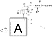
図1は、本発明の実施例に係る反射型表示装置1の構成を示す概略図である。反射型表示装置1は、反射型表示部10と、コネクタ部20と、制御部40とで構成される。ここで、反射型表示部10とコネクタ部20とは着脱可能であり、反射型表示部10がコネクタ部20に装着された状態を概略断面図で示したのが図2である。以下、図1および図2を参照して説明する。
FIG. 1 is a schematic diagram showing the configuration of a
反射型表示部10は、略板状の電気泳動方式による表示部である。電気泳動方式の表示部は、電力の非供給時に表示内容を保持する記憶性を有した表示部であり、表示する側の面には、表示信号を表示する表示画面11と、表示面12とを備える。また、表示する側の面の反対面には、接続部13を備える。
表示画面11および表示面12は、反射型表示部10の表示する面を2つに分離して設けられたものであり、一方の表示画面11は、外部から入力され、コネクタ部20を介して与えられる表示信号に基づいて情報を表示する。また、他方の表示面12は、制御部40内に記憶され、コネクタ部20を介して与えられる表示信号に基づいて表示パターンを表示すると共に、コネクタ部20に備えられた発光部21からの光を表示面12で反射して、反射光を受光部22に返す。接続部13は、コネクタ部20の接続部23と接続することにより、表示画面11および表示面12で表示する信号を受ける。
The
The
ここで、電気泳動方式の表示部について図示を略して概説する。電気泳動方式の表示部は、電位差による電気泳動により移動する性質を有する有機あるいは無機の粒子(電気泳動粒子)が内部に封入されたマイクロカプセルを、2種類の色にそれぞれ着色して表示部の透明電極を有する基板間に混入させて製造する。製造された表示部に対して、透明電極から電圧印加することによって、電気泳動粒子は一方の電極上に堆積するため、マイクロカプセルは同一方向に揃う。従って、表示部の観察者は、マイクロカプセル上に着色された一方の色を見ることになる。また、透明電極の印加電圧を逆極とすることで、マイクロカプセルは他方の向きとなるため、表示部の観察者は、マイクロカプセル上に着色された他方の色を見ることになる。更に、電圧印加により整列したマイクロカプセルは、印加した電圧を解除されても、双方の整列方向が安定して維持されるため、表示部における表示内容は保持される。
従って、電気泳動方式の表示部は、表示信号と、駆動電圧とが供給されることで、表示信号に従った表示を行い、以降、表示部の表示内容は、表示信号および駆動電圧が与えられなくても保持される。
Here, the electrophoretic display unit will be outlined with illustration omitted. In the electrophoretic display unit, microcapsules in which organic or inorganic particles (electrophoretic particles) having a property of being moved by electrophoresis due to a potential difference are enclosed are colored in two different colors, respectively. It is manufactured by mixing between substrates having transparent electrodes. When a voltage is applied from the transparent electrode to the manufactured display portion, the electrophoretic particles are deposited on one electrode, so that the microcapsules are aligned in the same direction. Therefore, the observer of the display unit sees one color colored on the microcapsule. Further, since the microcapsule is oriented in the other direction by setting the applied voltage of the transparent electrode to the opposite polarity, the observer of the display unit sees the other color colored on the microcapsule. Furthermore, since the microcapsules aligned by voltage application are stably maintained in both alignment directions even when the applied voltage is released, the display content in the display unit is maintained.
Therefore, an electrophoretic display unit is supplied with a display signal and a drive voltage to display according to the display signal. Thereafter, the display content of the display unit is given the display signal and the drive voltage. Retained even without.
コネクタ部20は、側面視が略凹状であり、反射型表示部10の表示する側の面と表示する側の面の反対面とを2面で挟み込む挟装部24と、一方の挟装部24にある発光部21および受光部22と、他方の挟装部24にある接続部23とを備える。
発光部21および受光部22は、挟み込んだ反射型表示部10の表示する側の面と対向する一方の挟装部24にあって、反射型表示部10の表示面12と対向した位置にあり、発光部21から発光された光が反射型表示部10の表示面12で反射され、反射光が受光部22に入るような位置関係で設置されている。
発光部21は、波長が800nm近傍の近赤外領域で、家庭用交流電源の周波数およびその整数倍の近傍を避けた周波数で変調された光を発光する。
また、受光部22は、発光部21が発光した光と同じ波長で周波数変調された光を選択して検出し、検出した光量を信号に変換する。
接続部23は、挟み込んだ反射型表示部10の表示する側の面の反対面と対向する他方の挟装部24にあって、反射型表示部10の接続部13と対向した位置にあり、反射型表示部10の接続部13と電気的に接続することにより、表示画面11および表示面12で表示する信号を反射型表示部10に送る。
The
The
The
The
The
制御部40は、電源と、外部から与えられる表示信号と、前記した受光部22が生成する信号とを入力することにより、反射型表示部10の表示を行う駆動信号を生成し、コネクタ部20を介して反射型表示部10に供給する。制御部40の詳細は後述する。また、制御部40と、コネクタ部20とは、ケーブル30で接続されている。
The
図3は、制御部40の構成を示す概略図である。制御部40は、表示信号記憶手段48と、表示信号選択手段43と、描画処理手段44と、駆動信号生成手段45と、駆動信号補正手段46と、接続制御手段47と、表示特性算出手段41と、表示特性記憶手段42とを備える。
表示信号記憶手段48は、読み取り専用の記憶装置(ROM)であり、表示面12で表示する表示信号を記憶している。表示信号選択手段43は、表示信号記憶手段48が記憶する表示信号、または、外部から与えられる表示信号のどちらか一方を選択する。描画処理手段44は、表示信号選択手段43が選択した表示信号を反射型表示部10で表示するための描画データを生成する。駆動信号生成手段45は、描画処理手段44が生成した描画データから、反射型表示部10を駆動する駆動信号を生成する。
また、表示特性算出手段41は、表示面12で表示している表示パターンにおいて、受光部22から送られる光量に関する信号に基づき、反射型表示部10の表示特性を算出して、表示特性に関する信号に変換する。表示特性記憶手段42は、揮発性の読み書き可能な記憶装置(RAM)であり、表示特性算出手段41が算出した反射型表示部10の表示特性に関する信号を記憶する。
ここで、駆動信号補正手段46は、表示特性記憶手段42が記憶している反射型表示部10の表示特性に関する信号を参照して、駆動信号生成手段45が生成した駆動信号を補正する。
接続制御手段47は、駆動信号補正手段46が補正した駆動信号を、コネクタ部20の接続部23と、反射型表示部10の接続部13とを介して、反射型表示部10に送る。
FIG. 3 is a schematic diagram illustrating the configuration of the
The display signal storage means 48 is a read-only storage device (ROM) and stores a display signal to be displayed on the
Further, the display characteristic calculation means 41 calculates the display characteristic of the
Here, the drive
The
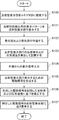
図4は、反射型表示部10をコネクタ部20に装着し、外部からの表示信号が反射型表示部10で表示されるまでの流れを示すフローチャートである。以下、前記した構成に基づいて説明する。
FIG. 4 is a flowchart showing a flow from when the
反射型表示部10はコネクタ部20に装着され、コネクタ部20の接続部23と反射型表示部10の接続部13とが電気的に接続状態になる(ステップS100)。
The
当該接続状態に遷移すると、先ず、制御部40の表示信号選択手段43は、表示信号記憶手段48の表示信号を選択する。描画処理手段44および駆動信号生成手段45は、選択された表示信号に基づいて、駆動信号を生成する。生成された駆動信号は、駆動信号補正手段46を通過して、接続制御手段47から反射型表示部10の表示面12に送られることにより、前記表示面12は表示信号記憶手段48に記憶されたパターンを表示する(ステップS101)。
When transitioning to the connection state, first, the display
発光部21および受光部22が作動する。即ち、発光部21から発光され、反射型表示部10の表示面12で反射された光は、受光部22で検出する。ここで、受光部22は、前記表示面12に表示されるパターンに応じた当該光の光量(反射光量)の変化を示す信号を生成し、制御部40の表示特性算出手段41に送る(ステップS102)。
The
表示特性算出手段41は、反射光量の変化を示す信号に基づき、反射型表示部10の表示特性を算出する。即ち、表示特性算出手段41は、前記表示面12に表示されたパターンにおける反射光量から、反射型表示部10の反射率を算出すると共に、前記表示面12に表示するパターンを変化させた際の反射光量の変化から、反射型表示部10の応答速度を算出する。算出した反射率および応答速度は信号に変換され、表示特性記憶手段42に記憶される(ステップS103)。
The display
制御部40の表示信号選択手段43は、外部から与えられる表示信号を選択することで、表示信号は外部から入力される(ステップS104)。
描画処理手段44および駆動信号生成手段45は、入力された表示信号に基づいて、駆動信号を生成する(ステップS105)。
The display
The
制御部40の駆動信号補正手段46は、記憶している反射型表示部10の表示特性に関する信号に基づいて、駆動信号の補正を行う。例えば、温度変動による反射型表示部10内部の粘性の変化が原因で、応答速度が低下していると判断された場合は、反射型表示部10の表示画面11に書き込む電圧を上げるか、または書き込み時間が長くなるように駆動信号を補正する(ステップS106)。
The drive signal correction means 46 of the
補正された駆動信号を、反射型表示部10に送ることで,反射型表示部10の表示画面11に表示されていた表示内容は全て消去され、外部から入力された表示信号により生成される画像が、反射型表示部10の表示画面11に表示される(ステップS107)。
By sending the corrected drive signal to the
以上述べたような実施例によれば、次のような効果がある。
(1)反射型表示部10は、表示面12の反射光量を検出する発光部21および受光部22および制御部40がコネクタ部20側に設けられているため、薄型化および軽量化が可能で携帯性に優れる。
(2)発光部21および受光部22は、コネクタ部20の挟装部24内に設けられているため、挟装部24が外部から発光・受光手段に入射する光を遮ることから、外部からの光による影響を受けることなく反射光量を検出できる。
(3)発光部21および受光部22で用いる光は、近赤外領域で周波数変調されているため、例えば蛍光灯のような外乱光の影響を受け難く、信頼性の高い検出ができる。
(4)外部から与えられた表示信号を表示する表示画面11と、反射型表示部10の表示特性を検出するための表示面12とは、分離して形成されているため、反射型表示部10の全域に表示画面を設ける場合と比較して、製造コストを抑えることができる。
The embodiment described above has the following effects.
(1) The
(2) Since the
(3) Since the light used in the
(4) Since the
なお、本発明は前述の実施例に限定されるものではなく、本発明の目的を達成できる範囲での変形および改良等は本発明に含まれるものである。
例えば、前記実施例では、コネクタ部20および制御部40は、分離された構造になっていることに代えて、コネクタ部20および制御部40は、一体となった構造であっても良い。
また、制御部40に備えられた表示特性算出手段41は、コネクタ部20にあって、コネクタ部20の発光部21および受光部22と一体になった構造であっても良い。
また、反射型表示部10の接続部13と、コネクタ部20の接続部23との接続は、電気信号を授受できる接続方法であれば、非接触方式でも良い。
また、発光部21および受光部22で用いる光の変調は、周波数変調に限らない。外乱光との識別が容易な変調方式であれば、変調はどのような方式でも良い。
また、反射型表示素子は、電気泳動式に限らない。表示内容について記憶性を備える反射型表示素子であれば、コレステリック液晶のような表示素子でも良い。
In addition, this invention is not limited to the above-mentioned Example, The deformation | transformation, improvement, etc. in the range which can achieve the objective of this invention are included in this invention.
For example, in the above-described embodiment, the
Further, the display characteristic calculation means 41 provided in the
Further, the connection between the
Further, the modulation of light used in the
The reflective display element is not limited to the electrophoretic type. A display element such as a cholesteric liquid crystal may be used as long as it is a reflective display element having a memory property for display contents.
1…反射型表示装置、10…反射型表示部、11…表示画面、12…表示面、13…接続部、20…コネクタ部、21…発光部、22…受光部、23…接続部、24…挟装部、40…制御部、41…表示特性算出手段、42…表示特性記憶手段、43…表示信号選択手段、44…描画処理手段、45…駆動信号生成手段、46…駆動信号補正手段、47…接続制御手段、48…表示信号記憶手段。
DESCRIPTION OF
Claims (8)
前記反射型表示部から着脱可能に構成されたコネクタ部と、
前記コネクタ部内に設けられ、前記反射型表示部の前記表示画面とは異なる位置にある表示面に対して発光するとともに、前記反射型表示部の表示面で反射される光量を検出する発光・受光手段とを備え、
前記コネクタ部は、前記反射型表示部の表示面を挟み込む挟装部を備え、
前記挟装部により、前記発光・受光手段に入射する外部からの光が遮光される
ことを特徴とする反射型表示装置。 A memory-type reflective display unit capable of retaining the display content of the display screen when power is not supplied;
A connector configured to be detachable from the reflective display unit;
Light emission / light reception that is provided in the connector unit and emits light to a display surface at a position different from the display screen of the reflective display unit and detects the amount of light reflected by the display surface of the reflective display unit Means and
The connector part includes a sandwiching part that sandwiches a display surface of the reflective display part,
A reflection type display device characterized in that external light incident on the light emitting / receiving unit is shielded by the sandwiching unit.
前記コネクタ部は、前記反射型表示部に対して表示信号を供給する接続部を備えることを特徴とする反射型表示装置。 The reflective display device according to claim 1,
The reflection type display device, wherein the connector part includes a connection part for supplying a display signal to the reflection type display part.
前記発光・受光手段は、当該挟装部にあって、当該挟装部が挟み込んだ前記反射型表示部の表示面と対向していることを特徴とする反射型表示装置。 The reflective display device according to claim 1 or 2 ,
The reflection type display device according to claim 1, wherein the light emitting / receiving unit is in the sandwiching portion and is opposed to a display surface of the reflective display portion sandwiched by the sandwiching portion.
前記発光・受光手段で前記光量の検出に用いられる光は、波長が近赤外領域の光であることを特徴とする反射型表示装置。 The reflection type display device according to any one of claims 1 to 3,
The light used for detecting the amount of light by the light emitting / receiving means is a light having a wavelength in the near infrared region.
前記発光・受光手段で前記光量の検出に用いられる光は、所定の周波数で変調されていることを特徴とする反射型表示装置。 The reflective display device according to any one of claims 1 to 4,
The reflection type display device, wherein the light used for detecting the amount of light by the light emitting / receiving means is modulated at a predetermined frequency .
前記反射型表示部の表示面は複数に分割されており、前記発光・受光手段は前記分割された表示面の少なくとも一つで反射される前記光量を検出することを特徴とする反射型表示装置。 The reflective display device according to any one of claims 1 to 5,
The reflective display surface of the display unit is divided into a plurality of light emitting and receiving means reflective display device characterized by detecting the amount of light reflected by at least one of said divided display surface .
前記発光・受光手段による前記光量の検出信号から前記反射型表示部の表示特性を算出して表示特性信号を生成し、当該表示特性信号に基づいて、前記反射型表示部の表示信号に基づき生成された駆動信号を補正し、補正された当該駆動信号に基づいて、前記反射型表示部の表示信号を前記コネクタ部に供給する制御部を備えることを特徴とする反射型表示装置。 The reflection type display device according to any one of claims 1 to 6,
A display characteristic signal is generated by calculating a display characteristic of the reflective display unit from a detection signal of the light amount by the light emitting / receiving unit, and generated based on the display signal of the reflective display unit based on the display characteristic signal It has been corrected driving signal, based on the corrected the driving signal, the reflection type display device a display signal of the reflective display unit, characterized in that it comprises a control unit for supplying to said connector portion.
前記反射型表示部は、電気泳動式表示素子であることを特徴とする反射型表示装置。 The reflection type display device according to any one of claims 1 to 7,
The reflection type display device is an electrophoretic display element.
Priority Applications (1)
| Application Number | Priority Date | Filing Date | Title |
|---|---|---|---|
| JP2003415442A JP4525068B2 (en) | 2003-12-12 | 2003-12-12 | Reflective display device, reflective display member used therefor, and connector |
Applications Claiming Priority (1)
| Application Number | Priority Date | Filing Date | Title |
|---|---|---|---|
| JP2003415442A JP4525068B2 (en) | 2003-12-12 | 2003-12-12 | Reflective display device, reflective display member used therefor, and connector |
Publications (3)
| Publication Number | Publication Date |
|---|---|
| JP2005173394A JP2005173394A (en) | 2005-06-30 |
| JP2005173394A5 JP2005173394A5 (en) | 2007-02-01 |
| JP4525068B2 true JP4525068B2 (en) | 2010-08-18 |
Family
ID=34734936
Family Applications (1)
| Application Number | Title | Priority Date | Filing Date |
|---|---|---|---|
| JP2003415442A Expired - Fee Related JP4525068B2 (en) | 2003-12-12 | 2003-12-12 | Reflective display device, reflective display member used therefor, and connector |
Country Status (1)
| Country | Link |
|---|---|
| JP (1) | JP4525068B2 (en) |
Citations (4)
| Publication number | Priority date | Publication date | Assignee | Title |
|---|---|---|---|---|
| JPS6124724U (en) * | 1984-07-17 | 1986-02-14 | 旭硝子株式会社 | dimming mirror device |
| JPH05173491A (en) * | 1991-12-25 | 1993-07-13 | Ricoh Co Ltd | Display member |
| JPH06110088A (en) * | 1992-09-25 | 1994-04-22 | Nippon Mektron Ltd | Driving system of electrophoretic display device |
| JP2001290178A (en) * | 2000-02-04 | 2001-10-19 | Fuji Xerox Co Ltd | Picture display device, picture display medium and picture display control device |
-
2003
- 2003-12-12 JP JP2003415442A patent/JP4525068B2/en not_active Expired - Fee Related
Patent Citations (4)
| Publication number | Priority date | Publication date | Assignee | Title |
|---|---|---|---|---|
| JPS6124724U (en) * | 1984-07-17 | 1986-02-14 | 旭硝子株式会社 | dimming mirror device |
| JPH05173491A (en) * | 1991-12-25 | 1993-07-13 | Ricoh Co Ltd | Display member |
| JPH06110088A (en) * | 1992-09-25 | 1994-04-22 | Nippon Mektron Ltd | Driving system of electrophoretic display device |
| JP2001290178A (en) * | 2000-02-04 | 2001-10-19 | Fuji Xerox Co Ltd | Picture display device, picture display medium and picture display control device |
Also Published As
| Publication number | Publication date |
|---|---|
| JP2005173394A (en) | 2005-06-30 |
Similar Documents
| Publication | Publication Date | Title |
|---|---|---|
| JP5842419B2 (en) | Head-up display device | |
| JP4600260B2 (en) | Liquid crystal display | |
| TWI269132B (en) | Control device | |
| JP5975285B2 (en) | Laser scanning display device | |
| KR102268967B1 (en) | Display device | |
| WO2014024766A1 (en) | Display apparatus | |
| US20180088266A1 (en) | Display apparatus | |
| US20110298757A1 (en) | Touch panel input system and input pen | |
| JP2005148735A (en) | Display device | |
| GB2466846A (en) | Sensor system and method for detecting a property of light emitted from at least one display area of a display device | |
| US20160238773A1 (en) | Display device | |
| JP4477903B2 (en) | Lamp driving device, backlight assembly using the same, and liquid crystal display device using the same | |
| EP3312665A1 (en) | Display apparatus | |
| US20170280115A1 (en) | Laser projection display device | |
| US20180156961A1 (en) | Illumination device and display device | |
| TW200428124A (en) | Electrophoretic display devices | |
| JP2005055293A (en) | Virtual image type meter | |
| JP6108169B2 (en) | Color mixing device and display device | |
| US11415735B2 (en) | Liquid crystal display device | |
| JP4525068B2 (en) | Reflective display device, reflective display member used therefor, and connector | |
| JP2007322889A (en) | Display device | |
| JP2005181831A (en) | Display device and method for controlling display device | |
| CN115407543A (en) | Light-emitting module and display device | |
| KR100967259B1 (en) | Display apparatus for mobile terminal | |
| JP2005070131A (en) | Display device |
Legal Events
| Date | Code | Title | Description |
|---|---|---|---|
| A521 | Written amendment |
Free format text: JAPANESE INTERMEDIATE CODE: A523 Effective date: 20061208 |
|
| A621 | Written request for application examination |
Free format text: JAPANESE INTERMEDIATE CODE: A621 Effective date: 20061208 |
|
| RD04 | Notification of resignation of power of attorney |
Free format text: JAPANESE INTERMEDIATE CODE: A7424 Effective date: 20070403 |
|
| A131 | Notification of reasons for refusal |
Free format text: JAPANESE INTERMEDIATE CODE: A131 Effective date: 20100202 |
|
| A521 | Written amendment |
Free format text: JAPANESE INTERMEDIATE CODE: A523 Effective date: 20100401 |
|
| TRDD | Decision of grant or rejection written | ||
| A01 | Written decision to grant a patent or to grant a registration (utility model) |
Free format text: JAPANESE INTERMEDIATE CODE: A01 Effective date: 20100511 |
|
| A01 | Written decision to grant a patent or to grant a registration (utility model) |
Free format text: JAPANESE INTERMEDIATE CODE: A01 |
|
| A61 | First payment of annual fees (during grant procedure) |
Free format text: JAPANESE INTERMEDIATE CODE: A61 Effective date: 20100524 |
|
| FPAY | Renewal fee payment (event date is renewal date of database) |
Free format text: PAYMENT UNTIL: 20130611 Year of fee payment: 3 |
|
| R150 | Certificate of patent or registration of utility model |
Free format text: JAPANESE INTERMEDIATE CODE: R150 |
|
| FPAY | Renewal fee payment (event date is renewal date of database) |
Free format text: PAYMENT UNTIL: 20130611 Year of fee payment: 3 |
|
| LAPS | Cancellation because of no payment of annual fees |