JP4523381B2 - Packet communication device - Google Patents
Packet communication device Download PDFInfo
- Publication number
- JP4523381B2 JP4523381B2 JP2004316400A JP2004316400A JP4523381B2 JP 4523381 B2 JP4523381 B2 JP 4523381B2 JP 2004316400 A JP2004316400 A JP 2004316400A JP 2004316400 A JP2004316400 A JP 2004316400A JP 4523381 B2 JP4523381 B2 JP 4523381B2
- Authority
- JP
- Japan
- Prior art keywords
- server
- bandwidth
- service
- packet
- interfaces
- Prior art date
- Legal status (The legal status is an assumption and is not a legal conclusion. Google has not performed a legal analysis and makes no representation as to the accuracy of the status listed.)
- Expired - Fee Related
Links
Images


Classifications
-
- H—ELECTRICITY
- H04—ELECTRIC COMMUNICATION TECHNIQUE
- H04L—TRANSMISSION OF DIGITAL INFORMATION, e.g. TELEGRAPHIC COMMUNICATION
- H04L12/00—Data switching networks
- H04L12/28—Data switching networks characterised by path configuration, e.g. LAN [Local Area Networks] or WAN [Wide Area Networks]
- H04L12/2854—Wide area networks, e.g. public data networks
Description
本発明は、IP(Internet Protocol)ネットワークを構成するルータに関するものである。さらに詳しくは、サーバサイトとIPネットワークの接続点でサービス毎にトラフィックを分類してそれぞれの流量を制御し、サービス毎にユーザへの応答を保証する方法および装置に関する。 The present invention relates to a router constituting an IP (Internet Protocol) network. More particularly, the present invention relates to a method and apparatus for classifying traffic for each service at a connection point between a server site and an IP network, controlling each flow rate, and ensuring a response to a user for each service.
複数のサービスをネットワークを介して提供する際、それぞれのサービス品質を保証するために、ルータのQoS(Quality of Service)機能が用いられる。QoS機能を用いることで、接続回線内で個々のサービスのパケットが利用する帯域を設定し、優先度の高いサービスを優先してユーザに提供できる。 When providing a plurality of services via a network, a QoS (Quality of Service) function of the router is used to guarantee each service quality. By using the QoS function, it is possible to set the bandwidth used by each service packet within the connection line, and to give priority to the service to the user.
QoS機能は、フローを単位として帯域制御や優先制御を行う機能である。ここで、フローとは、TCP(Transmission Control Protocol)あるいはUDP(User Datagram Protocol)のポート番号や送信元あるいは宛先IPアドレスの組み合わせが一致するパケットの集合で表される。サービス要求を受信する入力側ネットワークインターフェース及びサーバが接続される出力側ネットワークインターフェースの双方でこのQoS機能が利用できる。 The QoS function is a function that performs bandwidth control and priority control in units of flows. Here, the flow is represented by a set of packets in which a combination of a TCP (Transmission Control Protocol) or UDP (User Datagram Protocol) port number and a source or destination IP address matches. This QoS function can be used in both the input side network interface that receives the service request and the output side network interface to which the server is connected.
単一のサーバ上で複数のサービスを提供する場合、ユーザにとって優先度の低いサービスのパケットをサーバが大量に受信してその要求を処理すると、そのサービスの負荷が上昇してサーバの処理リソースの大半を占め、ユーザにとって優先度の高い他のサービスの品質が低下する場合がある。このため、サーバの処理リソースを複数のサービスが共用する場合は、複数のサービス間で優先度に差を付け、優先度の高いサービスを優先的にユーザに提供することが望ましい。 When providing multiple services on a single server, if the server receives a large number of low-priority service packets for the user and processes the request, the load on the service increases and the processing resources of the server increase. The quality of other services that occupy the majority and have high priority for the user may deteriorate. For this reason, when a plurality of services share the processing resources of the server, it is desirable to differentiate the priority among the plurality of services and to provide the user with a higher priority service preferentially.
例えば、大容量のファイル転送に用いられるFTP(File Transfer Protocol)が占有する帯域の最大値を回線帯域幅の30%に抑え、残りを業務用アプリケーションのインターフェースとして用いられるHTTP(Hyper Text Transfer Protocol)や電子メールの取得に用いられるSMTP(Simple Mail Transer Protocol)で利用し、FTPによるファイル転送での回線帯域の占有を防ぐことが考えられる。 For example, the maximum bandwidth occupied by FTP (File Transfer Protocol) used for large-capacity file transfer is limited to 30% of the line bandwidth, and the rest is HTTP (Hyper Text Transfer Protocol) used as an interface for business applications. It can be used for SMTP (Simple Mail Transer Protocol), which is used to obtain e-mails, and to prevent occupying the line bandwidth in FTP file transfer.
サービス毎の優先度を設定するためには、ルータのサーバ接続側ネットワークインターフェースで、QoS機能によりそれぞれのサービスのパケットが占有する帯域幅に制限を設けることで、それぞれのサービスによって占有されるサーバリソースを間接的に制限することが行われる。 In order to set the priority for each service, the server resources occupied by each service can be set by limiting the bandwidth occupied by each service packet by the QoS function at the server connection side network interface of the router. Indirect restriction is performed.
ルータは、CPU及びその周辺装置で構成される制御部を持ち、この制御部が、OSPF(Open Shortest PathFirst)やBGP(Border Gateway Protocol)等の経路制御プロトコル処理や、telnetやHTTPを用いた設定管理用ユーザインターフェースの提供を行う。ネットワークサービスの多様化に伴い、高機能化するために、CPUまたはネットワークプロセッサ、及びそのソフトウェアで構成されるサーバをルータの内部に配置することが行われる。サーバは、ルータ内部のスイッチインターフェースを介してネットワークインターフェースに接続される。 The router has a control unit consisting of a CPU and its peripheral devices, and this control unit uses routing control protocol processing such as OSPF (Open Shortest PathFirst) and BGP (Border Gateway Protocol), and settings using telnet and HTTP. Provides a management user interface. Along with the diversification of network services, in order to achieve higher functionality, a server composed of a CPU or network processor and its software is placed inside the router. The server is connected to the network interface via a switch interface inside the router.
このようなルータ内に配備されたサーバに対してルータのQoS機能を適用し、サーバが提供するサービス毎のサービス品質を保証する場合、サーバ毎にQoS機能を実現するための機構を配備することは、ルータのコスト増大につながる。 When applying the QoS function of a router to a server deployed in such a router and guaranteeing the quality of service for each service provided by the server, a mechanism for realizing the QoS function should be deployed for each server. This increases the cost of the router.
コストの増大を抑えるために既存のルータの構成を踏襲する場合、サービス毎の通信品質を保証するためには、ユーザからの要求パケットを受信する複数のネットワークインターフェースに対して一律に、あるいは利用実績に応じて帯域制限を行う。 When following the existing router configuration to suppress the increase in cost, in order to guarantee the communication quality for each service, it can be used uniformly for multiple network interfaces that receive user request packets, or it has been used. Bandwidth is limited according to
上記のように、ユーザからの要求パケットを受信する複数のネットワークインターフェースに対して一律に、あるいは利用実績に応じて帯域制限を行う方法でサーバが受信するサービス要求を一定の範囲内に制限すると、次の問題が生じる。すなわち、ユーザからのサービス要求にネットワークインターフェース毎に偏りがあり、あるネットワークインターフェースで受信するサービス要求がそのネットワークインターフェースでの既定値に達していない場合、サーバに発生する余剰リソースを、他のネットワークインターフェースを介して接続したユーザが利用できず無駄になることが課題となる。 As described above, if the service request received by the server is limited within a certain range by a method that limits the bandwidth according to a plurality of network interfaces that receive a request packet from the user or according to the usage record, The following problems arise: That is, when there is a bias in the service request from the user for each network interface, and the service request received at a certain network interface does not reach the default value at that network interface, surplus resources generated in the server are transferred to other network interfaces. It becomes a problem that a user connected through the network cannot be used and is wasted.
また、ルータ内部のサーバで複数のサービスが提供され、それぞれについて最大制限リソースが規定され、この規定以上にサーバリソースを消費しないよう、ネットワークインターフェースでサービス要求の最大値を制限する場合を考える。この場合、サーバ上のあるサービスが最大制限リソース以下のリソースしか消費しないと、このサービスが余剰リソースを持つ。この余剰リソースを他のサービスに割り当ててサーバリソースを効率的に利用できないことが課題となる。 Also, consider a case in which a plurality of services are provided by a server inside the router, a maximum restriction resource is defined for each, and the maximum value of a service request is restricted by a network interface so that server resources are not consumed more than this regulation. In this case, if a service on the server consumes resources that are less than or equal to the maximum limit resource, this service has surplus resources. The problem is that server resources cannot be efficiently used by allocating these surplus resources to other services.
本発明の通信装置は、外部よりパケットを受信する複数のインターフェースと、複数のインターフェースと接続され外部へ複数のサービスを提供するサーバと、インターフェースおよびサーバを相互に接続するバスと、複数のインターフェースが受信するパケット量の総和を管理する帯域監視テーブルとを備え、帯域監視テーブルを参照して各ネットワークインターフェースからサーバに中継するパケットの量を制御することを特徴とする。 The communication apparatus of the present invention includes a plurality of interfaces that receive packets from the outside, a server that is connected to the plurality of interfaces and provides a plurality of services to the outside, a bus that interconnects the interfaces and the servers, and a plurality of interfaces. A bandwidth monitoring table for managing the total amount of received packets, and controlling the amount of packets relayed from each network interface to the server with reference to the bandwidth monitoring table.
この構成により、複数のインターフェースを経由して、サービスを提供するサーバに入力されるパケット量を監視することができ、それをQoS制御に反映することができる。 With this configuration, it is possible to monitor the amount of packets input to a server that provides a service via a plurality of interfaces, and reflect this in QoS control.
ここで、複数のインターフェースがそれぞれ帯域監視テーブルを備え、複数のインターフェース同士が自己の受信するパケットの量を他のインターフェースに通知し合うことにより、帯域監視テーブルは前記複数のインターフェースそれぞれが受信するパケットの量を記憶し、パケット量の総和を算出するように構成することができる。 Here, each of the plurality of interfaces has a bandwidth monitoring table, and each of the plurality of interfaces notifies the other interface of the amount of packets received by itself, so that the bandwidth monitoring table receives the packets received by each of the plurality of interfaces. Can be stored, and the total amount of packets can be calculated.
また、帯域監視テーブルは、フロー識別子、フロー識別子で識別されるフローの最大帯域、ネットワークインターフェース毎のフローの入力帯域及び出力帯域、全てのネットワークインターフェースでのフローの入力帯域の総和及び出力帯域の総和からなるエントリを持つように構成するのが好適である。これにより、サービス毎に処理すべきデータ量を適切に制御することができる。 In addition, the bandwidth monitoring table includes a flow identifier, a maximum bandwidth of the flow identified by the flow identifier, a flow input bandwidth and an output bandwidth for each network interface, a sum of flow input bandwidths and a sum of output bandwidths in all network interfaces. It is preferable to have an entry consisting of Thereby, the data amount which should be processed for every service can be controlled appropriately.
さらにサービス情報登録テーブルを有し、サービス情報登録テーブルは、フロー識別子、サーバ識別子、サービス種別、割り当てリソースから成るエントリを持ち、エントリは、サーバ識別子で識別されるサーバ上のサーバ種別で識別されるサービスが、サーバからどれだけのリソースを割り当てられているか、および、どのフロー識別子を有するフローが当該サービスで処理されているかを示すことが好適である。 The service information registration table further includes an entry including a flow identifier, a server identifier, a service type, and an allocated resource, and the entry is identified by the server type on the server identified by the server identifier. It is preferable to indicate how many resources the service has been allocated from the server and which flow identifiers are being processed by the service.
さらに、サーバでサービス毎のリソース利用状況を監視し、サービス情報登録テーブルの割り当てリソースを、リソース利用状況に応じて更新することにより、サーバのリソースを効率よく利用することができる。 Furthermore, by monitoring the resource usage status for each service by the server and updating the allocated resource of the service information registration table according to the resource usage status, the server resources can be used efficiently.
さらに、最大帯域計算テーブルを有し、最大帯域計算テーブルは、フロー識別子とリソース比を含むエントリを持ち、帯域監視テーブルへあるフローのエントリを追加する際、最大帯域計算テーブルを参照して、フローの最大帯域を設定することにより、さらにリソースを有効利用することができる。 Furthermore, the maximum bandwidth calculation table has an entry including a flow identifier and a resource ratio. When adding an entry of a flow to the bandwidth monitoring table, the maximum bandwidth calculation table refers to the maximum bandwidth calculation table and By setting the maximum bandwidth, resources can be used more effectively.
上記の例では、サーバリソース管理機能部をネットワークインターフェースに設けたが、逆にネットワークインターフェースの外部に設けることもできる。ここでは、サーバリソース管理機能部が帯域監視テーブルを備え、複数のインターフェースが自己の受信するパケットの量をサーバリソース管理機能部に通知することにより、帯域監視テーブルは複数のインターフェースそれぞれに入力するパケットの量を蓄積し、パケット量の総和を算出することができる。 In the above example, the server resource management function unit is provided in the network interface, but conversely, it may be provided outside the network interface. Here, the server resource management function unit has a bandwidth monitoring table, and the plurality of interfaces notify the server resource management function unit of the amount of packets received by the plurality of interfaces, so that the bandwidth monitoring table inputs packets to each of the plurality of interfaces. The total amount of packets can be calculated.
また、帯域監視テーブルは、所定のサーバーで提供される所定のサービスに対応するフロー毎に、複数のインターフェースが受信するパケット量の総和を管理することが好適である。これにより、サービス毎に処理すべきデータ量を適切に制御することができ、サーバーのリソースを効率的に使用することができる。 Further, it is preferable that the bandwidth monitoring table manages the total amount of packets received by a plurality of interfaces for each flow corresponding to a predetermined service provided by a predetermined server. Thereby, the amount of data to be processed for each service can be appropriately controlled, and server resources can be used efficiently.
また、本発明の他の態様では、ユーザからのデータを入力回線より受信する複数のインターフェースと、複数のインターフェースと接続され複数のサービスを提供するサーバに接続される出力回線と、所定のサーバーで提供される所定のサービスに対応するフロー毎に、複数のインターフェースが受信するデータ量の総和を管理する、サーバーリソース管理機能部とを有し、フロー毎に、前記複数のインターフェースから前記出力回線に出力されるデータ量を制御することを特徴とする。 In another aspect of the present invention, a plurality of interfaces that receive data from a user from an input line, an output line that is connected to the plurality of interfaces and is connected to a server that provides a plurality of services, and a predetermined server A server resource management function unit that manages a total amount of data received by a plurality of interfaces for each flow corresponding to a predetermined service to be provided, and for each flow from the plurality of interfaces to the output line; It controls the amount of data to be output.
ここで、サーバーリソース管理機能部は、所定のサーバーで提供される所定のサービスに対応するフロー毎に、最大帯域を管理し、複数のインターフェースから、所定のサーバーで提供される所定のサービスに対して出力されるデータ量を、最大帯域以下に制御することもできる。 Here, the server resource management function unit manages the maximum bandwidth for each flow corresponding to the predetermined service provided by the predetermined server, and for the predetermined service provided by the predetermined server from a plurality of interfaces. It is also possible to control the amount of data that is output below the maximum bandwidth.
さらに、サーバリソース管理機能部は、サーバーから当該サーバーのリソースの状態を受信し、当該リソースの状態を反映して最大帯域を変更することもできる。 Furthermore, the server resource management function unit can receive the resource status of the server from the server and change the maximum bandwidth by reflecting the resource status.
また、本発明の通信方法は、ユーザからのデータを複数のインターフェースで受信し、これを経由して複数のサービスを提供するサーバに出力する際に、所定のサーバーで提供される所定のサービスに対応するフロー毎に、複数のインターフェースが受信するデータ量の総和を管理し、フロー毎に、複数のインターフェースから出力回線に出力されるデータ量を制御することを特徴とする。本発明は、背景技術において課題となる、
(1)サーバに発生する余剰リソースをネットワークインターフェースを介して接続したユーザが利用できないことと、
(2)余剰リソースを他のサービスに割り当ててサーバリソースを効率的に活用できないことを解決するものである。
The communication method of the present invention receives data from a user through a plurality of interfaces and outputs the data to a predetermined service provided by a predetermined server when the data is output to a server that provides a plurality of services via the interface. The total amount of data received by a plurality of interfaces is managed for each corresponding flow, and the amount of data output from the plurality of interfaces to the output line is controlled for each flow. The present invention is a problem in the background art,
(1) the surplus resource generated in the server cannot be used by the user connected through the network interface;
(2) It solves that server resources cannot be efficiently used by allocating surplus resources to other services.
(1)の課題に対して、本発明のルータでは、内部スイッチインターフェースに接続されたサーバは、自身が提供するサービス毎の最大利用可能リソースを、直接あるいはルータ制御部を介して全てのネットワークインターフェースのサーバリソース管理機能へ通知する。 In response to the problem (1), in the router of the present invention, the server connected to the internal switch interface transmits the maximum available resource for each service provided by itself, either directly or via the router control unit. To the server resource management function.
ネットワークインターフェース上のサーバリソース管理機能は、サービス毎の最大利用可能リソースをサーバ識別子と関連付けて保持する機能を持つ。また、サービス種類毎に決定される、リソースあたりの平均占有帯域を用いて、この最大利用可能リソースを越えない範囲で処理可能なユーザ要求の帯域幅を、サービス識別子と関連付けて保持する機能を持つ。 The server resource management function on the network interface has a function of holding the maximum available resource for each service in association with the server identifier. In addition, using the average occupied bandwidth per resource determined for each service type, it has a function to hold the bandwidth of user requests that can be processed within a range not exceeding this maximum available resource in association with the service identifier. .
また、ルータのネットワークインターフェースそれぞれでユーザ端末から受信したサービス要求の帯域幅を保持し、全てのネットワークインターフェースでのサービス要求帯域幅の総和を、サービス毎に管理する機能を持つ。 In addition, each network interface of the router has a function of holding the bandwidth of the service request received from the user terminal and managing the sum of the service request bandwidths of all the network interfaces for each service.
ネットワークインターフェース上のインターフェース間連携機能は、サーバリソース管理機能が保持する、ネットワークインターフェースがユーザ端末から受信したサービス要求の帯域幅を、他のネットワークインターフェースのインターフェース間連携機能との間でお互いに通知する機能を持つ。 The inter-interface cooperation function on the network interface notifies the bandwidth of the service request received from the user terminal by the network interface held by the server resource management function with the inter-interface cooperation function of other network interfaces. Has function.
サーバリソース管理機能は、全てのネットワークインターフェース上のサービス要求帯域幅の和が、あらかじめ設定された、サービス毎の最大帯域幅を超過した場合、ネットワークインターフェース上で該当するパケットを廃棄することで、サービス要求が規定内に収まるよう調整を行う。このパケットの廃棄は、それぞれのネットワークインターフェースに対して一律の割合で、あるいはあらかじめそれぞれに設定された優先度に従って行われる。 When the sum of the service request bandwidths on all network interfaces exceeds the preset maximum bandwidth for each service, the server resource management function discards the corresponding packet on the network interface, Make adjustments to ensure that requirements are within specifications. This packet is discarded at a uniform rate for each network interface or according to a priority set in advance.
(2)の課題に対して、本発明のルータでは、ルータの内部スイッチインターフェースに接続されたサーバ上の複数のサービスを、サーバリソース監視機能が監視する。サーバリソース監視機能は、サーバ上の複数のサービスそれぞれが占有しているサーバの処理リソースの量を監視し、サービス識別子と占有処理リソースとを関連づけて保持し、最大トランザクション数通知機能へ通知する。 In response to the problem (2), in the router of the present invention, the server resource monitoring function monitors a plurality of services on the server connected to the internal switch interface of the router. The server resource monitoring function monitors the amount of server processing resources occupied by each of a plurality of services on the server, holds the service identifier and the occupied processing resource in association with each other, and notifies the maximum transaction number notification function.
最大トランザクション数通知機能は、サービス識別子と最大トランザクション数とを関連付けて保持し、全てのネットワークインターフェースに通知する機能を持つ。ここで、サービス毎の最大トランザクション数を求めるには、サービス毎に、現在の占有処理リソースと最低保証リソースのうち少ない方を選択し、これらの値の和をサーバ全体のリソースから引いて”サーバの余剰リソース”を求める。
この余剰リソースをあらかじめ設定された割合に従って各サービスに割り当てる。そして、サービス毎に平均化された、トランザクションに対して消費されるサーバリソースの割合を用いて、サービス毎の余剰リソースをサービス毎に増加可能なトランザクション数へと変換する。これに現在のトランザクション数と合わせることで、サービス毎の最大トランザクション数とする。
The maximum transaction number notifying function has a function of storing a service identifier and the maximum number of transactions in association with each other and notifying all network interfaces. Here, to obtain the maximum number of transactions for each service, select the smaller of the current dedicated processing resources and the minimum guaranteed resources for each service, and subtract the sum of these values from the resources of the entire server. Of surplus resources ”.
This surplus resource is allocated to each service according to a preset ratio. Then, the surplus resource for each service is converted into the number of transactions that can be increased for each service, using the ratio of server resources consumed for the transaction averaged for each service. By combining this with the current number of transactions, the maximum number of transactions for each service is obtained.
ネットワークインターフェースのフロー制御部は、通知されたサービス毎の最大トランザクション数をサービス毎のフロー検出条件と関連付けて保持し、この条件に該当するフローを検出した場合、あらかじめ設定された最大トランザクション数内にそのフローが収まるよう、パケット処理部あるいはパケット転送部に対してパケット廃棄の指示を出す。 The flow control unit of the network interface holds the notified maximum number of transactions for each service in association with the flow detection condition for each service, and when a flow corresponding to this condition is detected, it is within the preset maximum number of transactions. A packet discard instruction is issued to the packet processing unit or the packet transfer unit so that the flow is settled.
サーバ上で実行される複数のサービスそれぞれに割り当てるサーバリソースを保証しながら、サーバ全体で発生する余剰リソースを各サービスに割り当て、サービス品質をサーバリソースの範囲内で最大限に向上することを可能にする。 While guaranteeing server resources to be allocated to each of multiple services executed on the server, it is possible to allocate surplus resources generated in the entire server to each service and maximize the service quality within the range of server resources To do.
以下、本発明の実施に形態について図面を参照して説明する。 Embodiments of the present invention will be described below with reference to the drawings.
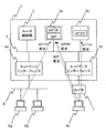
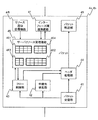
図1は、本発明のルータの概略図である。本発明のルータ1は、内部スイッチインターフェース5により接続された、ルータ制御部2、複数のサービスを提供可能な一つまたは複数のサーバ3a、3b、ネットワークインターフェース4a、4bによって構成される。本発明のルータ1は、スイッチネットワーク6あるいはルータ7で構成されたネットワークを介して、複数のユーザ端末8a〜8cからサービス要求を受信し、サーバ3a、3bのうち、サービス要求に該当するサーバがサービス要求を処理してユーザ端末に応答する。
FIG. 1 is a schematic diagram of a router of the present invention. The
本発明のルータ1では、後述するネットワークインターフェース4a、4b上のサーバリソース管理機能が、サービス毎のリソース割り当て状態及び、ユーザからのサービス要求を管理し、ユーザからのサービス要求により消費されるサーバ上のリソースが、あらかじめサービス毎に設定された閾値を越えないように、ネットワークインターフェース上でユーザからのサービス要求を制限することで、サービス毎のリソース割当を行い、サービス毎の品質を保証する。
In the
図2は、本発明のネットワークインターフェース4a、4bの概略構成図である。ネットワークインターフェースは、外部接続回線からパケットを受信するパケット受信部41、パケットの中継先を検索する中継先検索部42、あらかじめ設定されたフローに対して帯域制御、優先制御等を行うフロー制御部43、中継先ヘッダを付与するヘッダ処理部44、中継先ヘッダを付与したパケットをルータ内部のスイッチインターフェースに送信するパケット転送部45を持ち、さらにサーバリソース管理機能46及びインターフェース間連携機能47を持つことで構成する。パケット受信部41及び、中継先検索部42、ヘッダ処理部44、パケット転送部45は、ルータの通常のパケット中継処理を行う。
FIG. 2 is a schematic configuration diagram of the
図7はフロー制御部43が持つフロー管理テーブル431の例である。フロー管理テーブル431は、フロー識別子と、パケットの送信元あるいは宛先先のIPアドレス及びTCPあるいはUDPのポート番号の組み合わせで表される、フロー検出条件から成るエントリを有する。フロー制御部は、ルータ制御部2あるいはサーバ3a、3bからの通知でこのフロー管理テーブルのエントリを追加あるいは削除する機能を持つ。また、フロー制御部43は、受信したパケットヘッダがフロー制御の対象となるパケットのものである場合、ヘッダ処理部44に、パケットの廃棄あるいはパケットヘッダの書き換えを指示する機能を持つ。
FIG. 7 shows an example of a flow management table 431 that the
本発明のネットワークインターフェース4a、4bでは、サーバリソース監視機能46が、サーバ3a、3bで提供されるサービス毎に設定された最大利用可能リソースを管理する。この最大利用可能リソースに基づいて、フロー制御部がフロー毎の帯域制御を行うことで、ルータ1は、サーバ3a、3bでのサービス毎のリソース消費量を既定値内に制御する。
In the
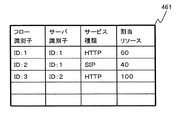
図3は、本発明のサーバリソース管理機能46に保持されるサービス情報登録テーブル461を示す。サービス情報登録テーブル461は、フロー識別子、サーバ識別子、サービス種別、割り当てリソースから成るエントリを持つ。一つのエントリは、あるサーバ上のあるサービスが、サーバからどれだけのリソースを割り当てられて使用可能であるかを表す。
FIG. 3 shows a service information registration table 461 held in the server
サーバリソース管理機能は、サーバ3a、3bあるいはルータ制御部2からの通知を受けて、このエントリを追加あるいは削除、更新する機能を持つ。
The server resource management function has a function of adding, deleting, or updating this entry in response to a notification from the
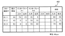
図4は、本発明のサーバリソース管理機能46に保持される帯域監視テーブル462をを示す。帯域監視テーブル462は、フロー識別子及び、最大帯域、ネットワークインターフェース毎の該当するフローの入力帯域及び出力帯域、全てのネットワークインターフェースでの該当するフローの入力帯域の総和、同じく出力帯域の総和から成るエントリを持つ。サーバリソース管理機能46は、サーバ3a、3bあるいはルータ制御部2からの通知によるサービス情報登録テーブル461へのエントリの登録あるいは削除に応じて、この帯域監視テーブル462へエントリを追加あるいは削除する機能を持つ。
FIG. 4 shows the bandwidth monitoring table 462 held in the server
また、サーバリソース管理機能46は、帯域監視テーブル462のエントリである、そのネットワークインターフェースで設定すべきフロー毎の最大帯域幅を、フロー識別子とともにフロー制御部に通知する機能を持つ。フロー制御部43は、サーバリソース管理機能46からのこの通知を受けて該当するフローの最大帯域幅を設定し、該当するフローに対して帯域制御を行う機能を持つ。
The server
また、サーバリソース管理機能46は、帯域監視テーブル462にエントリが存在するフローに関して、その入力帯域をフロー制御部から通知を受けて更新する機能を持つ。また、サーバリソース間機能46は、インターフェース間連携機能47との間で、帯域監視テーブル462にエントリが存在するフローに関して、フロー制御部から通知を受けた入力帯域を通知し、他のネットワークインターフェース上での入力帯域を受信する機能を持つ。
In addition, the server
図5はサーバリソース管理機能46が保持する最大帯域計算テーブル463を示す。最大帯域監視テーブル463は、フロー識別子及び、最大帯域を算出するための数値、例えばリソース比をエントリとする。このリソース比は、サーバに入力されるフローの単位帯域幅あたりのサーバリソース消費量をあらわす。サービス情報登録テーブル461中のあるフローを帯域監視テーブル462のエントリとして追加する場合を考える。テーブル461に示す、登録フローの割当リソースを、登録フローとサービス種別が一致するテーブル463中のエントリのリソース比で割った値が、登録フローに割り当てられる最大帯域となる。
FIG. 5 shows a maximum bandwidth calculation table 463 held by the server
サーバリソース管理機能46は、サーバ3a、3bあるいはルータ制御部2からの通知を受けて、この最大帯域計算テーブル463へエントリを追加あるいは削除する機能を持つ。
The server
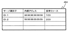
図6はサーバ情報テーブル464である。サーバリソース管理機能46は、後述するサーバ内の複数サービス間での余剰リソース配分で利用するため、サーバ情報テーブル464を保持する。サーバ情報テーブル464は、サーバ識別子及び、内部アドレス、保有リソースをエントリとする。内部アドレスは、サーバ識別子で表されるサーバに内部スイッチインターフェースを介してパケットを転送する場合に内部ヘッダの一部として付与するアドレスを表し、保有リソースは、サーバ識別子で表されるサーバが持つリソースを表す。
FIG. 6 is a server information table 464. The server
サーバリソース管理機能46は、サーバ3a、3bあるいはルータ制御部2からの通知を受けてサーバ情報テーブル464のエントリを追加あるいは削除する機能を持つ。
The server
ネットワークを介したサービスを提供する場合に、高品質なサービスを提供するためには、接続回線の帯域幅がボトルネックになる場合がある。このため、ルータ内の後続な内部スイッチインターフェースを介して、CPUあるいはネットワークプロセッサなどにより構成するサーバを配備することで、通信回線のボトルネックを解消し、ユーザからのサービス要求に対して、高品質なサービスを提供することが行われる。 When providing a service via a network, the bandwidth of the connection line may become a bottleneck in order to provide a high-quality service. For this reason, by deploying a server consisting of a CPU or network processor via the internal switch interface in the router, the bottleneck of the communication line is eliminated, and high quality services are provided for service requests from users. Services are provided.
通信回線のボトルネックが解消してユーザからのサービス要求が増加した場合、サーバのリソースがボトルネックとなる場合がある。ルータの外部にサーバを接続している場合、サーバとの間のネットワークインターフェースでフロー制御機能を利用し、ユーザからのサービス要求に上限を設けることで、サービス毎の消費リソースを一定範囲内に抑えられる。 When the bottleneck of the communication line is resolved and the service request from the user increases, the server resource may become a bottleneck. If a server is connected to the outside of the router, use the flow control function at the network interface with the server, and set an upper limit for the service request from the user, so that the resource consumption for each service is kept within a certain range. It is done.
しかしながら、ルータ内部のスイッチインターフェースを介してサーバを配備する場合、ルータの内部スイッチインターフェースがフロー制御機能を持たないため、入力側の全てのネットワークインターフェースでフロー制御機能を利用してユーザからのサービス要求に優先度を付けてサーバへ中継する必要がある。 However, when deploying a server via a switch interface inside the router, the internal switch interface of the router does not have a flow control function. Therefore, service requests from users using the flow control function on all network interfaces on the input side. Need to be given a priority and relayed to the server.
入力側のネットワークインターフェースでフロー制御を行う場合、ユーザからのサービス要求の分布にネットワークインターフェース毎に偏りがあると、サーバで余剰リソースが発生する。 When flow control is performed by the network interface on the input side, if the distribution of service requests from users is uneven for each network interface, surplus resources are generated in the server.
サーバで余剰リソースが発生した場合、設定値を越えるユーザ要求を受信し、フロー制御によりユーザ要求が制限されているネットワークインターフェースに対して、サーバの余剰リソースの分だけ設定値を拡大し、サーバリソースをユーザ要求に対して効率的に割り当てることが望ましい。 When surplus resources occur in the server, a user request exceeding the set value is received, and the set value is expanded by the surplus resource of the server for the network interface for which the user request is restricted by flow control. It is desirable to efficiently assign a user request.
本発明では、ネットワークインターフェース上のサーバリソース管理機能が、全てのネットワークインターフェース上のユーザ要求の受信状態を管理し、ユーザ要求の総和に応じて各ネットワークインターフェースからサーバに中継するユーザ要求の量を制御することで、サービス毎に設定されたリソースを効率的にユーザ要求に対して割り当てる。 In the present invention, the server resource management function on the network interface manages the reception status of user requests on all network interfaces, and controls the amount of user requests relayed from each network interface to the server according to the sum of user requests. Thus, resources set for each service are efficiently allocated to user requests.
図8は、本発明のサービス品質保証方式の実施の形態を示す概略図である。ここでは、ユーザ端末8aがサーバ3aに対してHTTPで、ユーザ端末8cがサーバ3bに対してHTTP及びSIPで、ユーザ端末8cがサーバ3cに対してHTTPでサービス要求を行う例を示す。
FIG. 8 is a schematic diagram showing an embodiment of the service quality assurance system of the present invention. Here, an example is shown in which the
ルータ1内のサーバ3a、3bでサービスを起動した後、サーバ3a、3bあるいはルータ制御部2は、ネットワークインターフェース4a及び4bのサーバリソース管理機能へ、サービス毎に、サーバ識別子及びサービス種別、割り当てリソースを通知する。ここでは、サーバ3aでHTTP及びSIPサービスを起動し、それぞれに60及び40のリソースを割り当てるものとする。
After starting the service on the
この時、ネットワークインターフェース4a、4bのサーバリソース管理機能46は、自身が保持するサービス情報テーブル461に、図3に示したようにエントリを作成する。フロー識別子は、エントリ毎に重複しない値を選択する。また同時に、帯域監視テーブル462に、図4に示したようにエントリを作成する。
この時、帯域監視テーブル462に登録されるサービス毎の最大帯域は、サービス情報テーブル461の割り当てリソースに、図5に示した最大帯域計算テーブル中の該当するリソース比を乗じた値を登録する。
At this time, the server
At this time, the maximum bandwidth for each service registered in the bandwidth monitoring table 462 is registered as a value obtained by multiplying the allocated resource in the service information table 461 by the corresponding resource ratio in the maximum bandwidth calculation table shown in FIG.
さらに、サーバリソース管理機能46は、サービス情報管理テーブル461に登録したサービスを要求するパケットを検出するために、フロー制御部43にフロー検出条件を設定する。フロー検出条件は、サーバのアドレス及びTCPあるいはUDPのポート番号を、サービス情報管理テーブル461のエントリ中のサーバ識別子及びサービス種別から検索して利用する。
Further, the server
ユーザ端末8a、8cがサーバを宛先とするサービス要求パケットを送信すると、サービス要求パケットはスイッチネットワーク6あるいはルータ7を介してルータ1へ送信される。ルータ1は、これらのパケットをネットワークインターフェース4a及び4bで受信する。ネットワークインターフェース内では、パケット受信部41がこれらのパケットを受信し、ヘッダ処理44へパケットを送信し、中継先検索部42及びフロー制御部43へパケットヘッダを通知する。
When the
中継検索部42では、パケットヘッダ中の宛先アドレスを元に中継先のアドレスを検索し、さらにこの中継先のアドレスを元に、出力先のネットワークインターフェースを検索する。中継先検索部42は、検索結果のネットワークインターフェースの識別子を中継先としてヘッダ処理部44に通知する。ヘッダ処理部44は、中継先検索部43から通知された中継先を内部ヘッダに格納し、パケット受信部41から受信した対応するパケットに付与して、パケット転送部45に送信する。パケット転送部45は、ヘッダ処理部44から受信したパケットの内部ヘッダを読み取り、ルータ内部のスイッチインターフェース5を介して、内部ヘッダに格納された中継先が指すネットワークインターフェースへパケットを送信する。
The
フロー制御部43では、パケット受信部41から受信したパケットヘッダを読み取り、自身が持つフロー管理テーブル431を参照し、ネットワークインターフェースで受信したパケットが、フロー制御の対象となるパケットであるかを判断する。
フロー制御部43は、フロー管理テーブル431のエントリに基づいて、サーバ3a、3b内のサービス毎のサービス要求パケットの入力帯域幅を監視する。そして、この入力帯域幅がフロー管理テーブル431中の該当するエントリの最大帯域幅を越えないように、ヘッダ処理部44に対して、必要に応じてパケットの廃棄を指示する。
The
The
このように、フロー制御部43で行われるパケット廃棄の指示により、サーバへのサービス要求パケットの帯域幅を制限するために、サーバリソース管理機能46は、全てのネットワークインターフェースでのサービス要求パケットの入力帯域幅を監視する。
Thus, in order to limit the bandwidth of the service request packet to the server according to the packet discard instruction performed by the
まず、フロー制御部43が、フロー管理テーブル431にエントリがあるフローについて、その入力帯域幅をサーバリソース管理機能46へ定期的に通知する。サーバリソース管理機能46は、フロー制御部43より通知された、自身のネットワークインターフェースでのサービス毎の入力帯域幅を監視テーブル462の該当するエントリに上書きする。
First, the
図9は他の実施例を示す。 FIG. 9 shows another embodiment.
インターフェース間連携機能47が、図9に示すように、他のネットワークインターフェースから、インターフェース識別子及び、フロー識別子、入力帯域幅を関連付けて受信する。そしてこれらの情報を、サーバリソース管理機能46へ定期的に通知する。サーバリソース管理機能46は、インターフェース間連携機能47から定期的に通知される、他のネットワークインターフェースでのサービス毎の入力帯域幅と、帯域監視テーブル462の該当するエントリに上書きする。
As shown in FIG. 9, the
また、インターフェース間連携機能47は、図9に示すように、サーバリソース管理機能46から通知された、サービス毎のサービス要求パケットの入力帯域幅を、ネットワークインターフェース識別子を付与して、自分意外の全てのネットワークインターフェースのインターフェース間連携機能へ通知する。
Further, as shown in FIG. 9, the
図4を再度参照して、本発明の機能を説明する。 Referring again to FIG. 4, the function of the present invention will be described.
ここで、全てのネットワークインターフェースでのサービス毎のサービス要求パケットの入力帯域幅を収集した結果、図4に示すように、フロー識別子が1であるフローの入力帯域幅が、ネットワークインターフェース4a、4bでそれぞれ75Mbps、15Mbpsとして帯域監視テーブル462に登録されているものとする。同様に、フロー識別子が2であるフローに対して、0Mbps、10Mbpsと、フロー識別子が3のフローに対して0Mbps、70Mbpsと、登録されているものとする。
Here, as a result of collecting the input bandwidth of the service request packet for each service in all the network interfaces, as shown in FIG. 4, the input bandwidth of the flow having the
フロー識別子2のフローについては、全てのネットワークインターフェースでの入力帯域幅の総和10Mbpsが、最大帯域として設定されている40bpsを越えないため、ネットワークインターフェース上での帯域制限を行わない。
For the flow with the
フロー識別子3のフローについては、全てのネットワークインターフェースでの入力帯域幅の総和70Mbpsが、最大帯域として設定されている50Mbpsを越えているため、ネットワークインターフェース4bで帯域制限を行い、入力帯域幅を50Mbpsに制限する。そのために、ネットワークインターフェース4b上のサーバリソース管理機能46は、フロー制御部43が持つフロー管理テーブル431の、フロー識別子3に関するエントリの最大帯域幅を50Mbpsに設定する。
For the flow with the
フロー識別子1のフローについては、全てのネットワークインターフェースでの入力帯域幅の総和90Mbpsが、最大帯域として設定されている30Mbpsを越えているため、ネットワークインターフェース4a、4bで帯域制限を行い、全体として入力帯域幅を30Mbpsに制限する。この際、一例では、それぞれのネットワークインターフェースに対して同じ割合で帯域制限を行う。その結果、このフローに対するネットワークインターフェース4a、4bでの最大帯域幅は、それぞれ3分の1づつとし、25Mbps、5Mbpsと設定される。この例では、各ユーザは公平に取り扱われる。あるいは、ネットワークインターフェースに優先順位を設け、例えばネットワークインターフェース4aに優先的に帯域を割り当て、余りを他のネットワークインターフェースに回すこともできる。
For the flow with the
図10は帯域監視テーブルの他の状態を示す。ここでは、ユーザ端末8cからサーバ3aへのHTTPサービス要求が停止した場合の動作の例を示す。ネットワークインターフェース4aのサーバリソース管理機能46は、ネットワークインターフェース4bのフロー制御部43が監視する入力帯域幅を、インターフェース間連携機能47を介して収集する。この結果、図10に示すように、サーバリソース管理機能46が保持する帯域監視テーブルでは、ネットワークインターフェース4bでのフロー識別子が1であるフローの入力帯域幅が0となる。
FIG. 10 shows another state of the bandwidth monitoring table. Here, an example of the operation when the HTTP service request from the
サーバリソース管理機能46は、インターフェース間連携機能47からの通知による、他のネットワークインターフェースでの入力帯域幅の更新に従い、ネットワークインターフェースの帯域制限値を再計算する。
The server
ここでは、ネットワークインターフェース4a、4bでの入力帯域幅が75Mbps、0Mbpsであることから、それぞれの帯域制限値を30Mbps、0Mbpsとする。ネットワークインターフェース4aでのHTTPサービスへのサービス要求パケットの入力帯域幅は、25Mbpsから30Mbpsへと増加した。これにより、ネットワークインターフェース4bでの入力帯域幅の減少によりサーバ3aに発生する余剰リソースを、ネットワークインターフェース4aが受信するサービス要求へと割り当てられた。
Here, since the input bandwidths at the
このように、全てのネットワークインターフェースで、サービス要求パケットの入力帯域幅の総和を常に管理することで、複数のネットワークインターフェース間でサービス要求パケットの偏りが出た場合に、その偏りによるサーバ上の余剰リソースを他のネットワークインターフェース上のサービス要求に割り当てられる。 In this way, by managing the sum of the input bandwidths of service request packets in all network interfaces, if there is a bias in service request packets among multiple network interfaces, surplus on the server due to the bias Resources can be assigned to service requests on other network interfaces.
上記の例では、複数のネットワークインターフェースの入力帯域幅を全て同じ割合で減少させたが、本発明のサーバリソース管理機能によれば、ネットワークインターフェースの優先度に重みづけを行うことで、あるネットワークインターフェースからのサービス要求に対して、優先的にサーバリソースを割り当てることも可能である。 In the above example, the input bandwidths of a plurality of network interfaces are all reduced at the same rate. However, according to the server resource management function of the present invention, a certain network interface is weighted by weighting the priority of the network interface. It is also possible to preferentially allocate server resources to service requests from
上記の実施形態では、サーバ上で提供するそれぞれのサービスに対して利用可能なサーバリソースを固定的に割り当て、フロー制御の最大帯域幅を制御することで、複数のネットワークインターフェース間で余剰リソースを融通しながら、サーバリソースの利用効率を最大化した。 In the above embodiment, server resources that can be used for each service provided on the server are fixedly allocated, and the maximum bandwidth for flow control is controlled, so that surplus resources can be accommodated between multiple network interfaces. However, the utilization efficiency of server resources was maximized.
しかしながら、単一のサーバ上で複数のサービスを提供する場合、サービス毎に割り当てられたリソースに対して、実際に利用されているリソースの割合は、サービス毎に異なる可能性がある。リソースの利用割合が100%に満たないサービスがある場合、このサービスのために確保されているリソースのうち、利用されていないリソースは余剰リソースとなる。このような余剰リソースは、利用割合が100%に達し、ネットワークインターフェース上でサービス要求パケットへの帯域制限が行われているサービスに、一時的に割り当てられることが望ましい。 However, when providing a plurality of services on a single server, the proportion of resources actually used with respect to the resources allocated for each service may be different for each service. When there is a service in which the resource usage rate is less than 100%, among the resources reserved for this service, the resources that are not used become surplus resources. It is desirable that such surplus resources are temporarily allocated to a service whose usage rate reaches 100% and whose bandwidth is limited to the service request packet on the network interface.
本発明の他の例ではさらに、サーバでサービス毎のリソース利用状況を監視し、サービス毎の余剰リソースをネットワークインターフェース上のサーバリソース管理機能に通知し、割り当てリソースをサーバ上のリソース利用状況に応じて更新する。これにより、あるサービスが余剰リソースを持つ場合に、他のサービスがこのリソースを使用可能とすることが出来る。 In another example of the present invention, the server monitors the resource usage status for each service, notifies the surplus resource for each service to the server resource management function on the network interface, and assigns the allocated resource according to the resource usage status on the server. Update. Thereby, when a certain service has a surplus resource, another service can use this resource.
図11に、サービス毎の余剰リソースを融通可能とする場合の本発明のサーバ3a、3bの構成の概略図を示す。サーバ3a、3bは、プロセスの形で実装される複数のサービス31a〜31zを監視し、それぞれのサービスが占有するサーバリソースを保持するリソース監視機能32を持つ。また、リソース監視機能32が収集したサービス毎のリソース利用状況をネットワークインターフェース4a、4b又はルータ制御部2に通知するリソース利用状況通知機能33を持つ。
FIG. 11 shows a schematic diagram of the configuration of the
図12にリソース監視機能32が持つ、サービス毎のリソース利用状況を管理するリソース利用状況管理テーブル321を示す。リソース利用状況管理テーブル321は、サービス種別及び、割り当てリソース、利用リソース、最大リソースをエントリとする。割り当てリソースはあらかじめサービス毎に割り当てられたリソースであり、利用リソースはそれぞれのサービスが実際に利用しているリソース、最大リソースは、サービス毎の利用リソースの総和がサーバリソースを越えないようにしながら、サービスリソースを最大限活用する場合の、サービスへの割り当てリソースを表す。
FIG. 12 shows a resource usage status management table 321 for managing the resource usage status for each service that the
図15に、サーバでのリソース監視を行った場合のネットワークインターフェース4a、4bの変形例を示す。ネットワークインターフェース4a、4bは、図2に示す場合と同様に、パケット受信部41及び、中継先検索部42、フロー制御部43、ヘッダ処理部44、パケット転送部45、サーバリソース管理機能46、インターフェース間連携機能47を持ち、さらに、サーバ3a、3bあるいはルータ制御部2からのサーバリソースの利用状況の通知を受ける、リソース通知受信機能48を持つ。
FIG. 15 shows a modification of the
リソース通知受信機能48は、サーバ3a、3bあるいはルータ制御部2から通知を受けたサーバリソース利用状況に基づいて、サーバリソース管理機能46が持つサービス情報登録テーブル461の割り当てリソースを更新する機能を持つ。
The resource
ここでは、サーバリソースが100である場合を例として示す。サーバリソースのうち60をHTTPサービスに、40をSIPサービスに割り当て、実際の利用リソースがそれぞれ、60及び10であったとする。また、この時の各ネットワークインターフェースでのサービス要求パケットの入力帯域幅は、図10に示した通りとする。 Here, a case where the server resource is 100 is shown as an example. Assume that 60 of the server resources are allocated to the HTTP service and 40 are allocated to the SIP service, and the actual resources used are 60 and 10, respectively. The input bandwidth of the service request packet at each network interface at this time is as shown in FIG.
図13はサーバでのリソース監視を行った場合のサービス情報登録テーブルである。 FIG. 13 is a service information registration table when resource monitoring is performed on the server.
リソース監視機能32はプロセスの動作状態を監視し、図12に示すようにリソース利用管理テーブルを更新する。そして、ネットワークインターフェース4a、4bあるいはルータ制御部2に対してリソースの利用状況を通知する。リソースの利用状況を受信した、ネットワークインターフェース上のリソース通知受信機能48は、サーバリソース管理機能46が持つ、サービス情報登録テーブル461を、図13に示すように更新する。
The
図14はサーバでのリソース監視を行った場合の帯域監視テーブルの例である。 FIG. 14 shows an example of a bandwidth monitoring table when resource monitoring is performed on the server.
サーバリソース管理機能46は、サービス情報登録テーブル461の更新を受けて、図14に示すように帯域監視テーブル462を更新する。サーバ3aのHTTPサービスの利用可能リソースが90に拡大したことで、ネットワークインターフェース3aからのHTTPサービス要求パケットの最大帯域幅が45Mbpsに拡大される。サーバリソース監視機能46は、フロー制御部43にこの変更を通知し、これに合わせて、フロー制御部43がフロー管理テーブル431を更新する。
Upon receiving the update of the service information registration table 461, the server
このようにして、サーバリソースの実際の利用状況を監視し、サーバリソース監視機能46に通知してフロー制御部43が持つフロー管理テーブル431に反映させることで、あるサービスで余剰リソースが発生している場合に、その余剰リソースを他のサービスに振り分けることが出来る。
In this way, the actual usage status of the server resource is monitored, notified to the server
以上、ルータ内部のサーバ上で提供されるサービスが消費するサーバリソースを一定値以下に抑えながら、余剰リソースを複数のネットワークインターフェース間あるいは複数のサービス間で融通するための方式を示した。 図16は、サーバリソース管理機能をネットワークインターフェースから独立して持つ本発明のルータの構成の一例を示す概略図である。 As described above, a method for accommodating surplus resources between a plurality of network interfaces or between a plurality of services while suppressing a server resource consumed by a service provided on a server in the router to a predetermined value or less has been shown. FIG. 16 is a schematic diagram showing an example of the configuration of the router of the present invention having a server resource management function independent of the network interface.
本方式を実施するための形態として、図15ではネットワークインターフェース内にサーバリソース管理機能を設ける例を示したが、図16に示すように、サーバリソース管理機能をネットワークインターフェースの外部に設け、ルータの内部スイッチインターフェースを介してネットワークインターフェース及びルータ制御部、サーバと接続した形態を用いることも可能である。 As an embodiment for implementing this method, FIG. 15 shows an example in which a server resource management function is provided in the network interface. However, as shown in FIG. 16, the server resource management function is provided outside the network interface, It is also possible to use a form connected to a network interface, router control unit, and server via an internal switch interface.
本発明は、IPネットワークを構成するルータに関する発明であり、今後ネットワークへの高機能化要求が強まるのに伴い、ネットワーク上で提供されるサービスの品質を確保するために用いられると考えられる。 The present invention relates to a router that constitutes an IP network, and is considered to be used to ensure the quality of services provided on the network as the demand for higher functionality in the network increases.
1 ルータ
2 ルータ制御部
3a、3b サーバ
4a、4b ネットワークインターフェイス
5 内部スイッチインターフェース
DESCRIPTION OF
Claims (10)
そのネットワークインターフェースで帯域制限を含むフロー制御を行うことが可能なパケット通信装置であって、
前記各ネットワークインターフェースが前記パケット通信装置内部のサーバに転送するパケットに対して帯域制御を行う機能を持ち、
前記帯域制御を行う機能が、
前記パケット通信装置内部で、サーバを宛先とするサービス要求パケットが占有する帯域幅を、各サーバのサービス毎に監視し、
前記パケット通信装置内部で、サーバで実行されるサービスに対してユーザ端末から送信されたサービス要求パケットの帯域幅の上限を既定値以内に制限することで、サービス毎に消費されるサーバリソースを一定値以内に制限することを特徴とするパケット通信装置。 One or more servers that provide network services to user terminals, one or more network interfaces that receive external packets, and a control unit that controls the packet communication device are connected via an internal switch network. ,
A packet communication device capable of performing flow control including bandwidth limitation at the network interface,
Each network interface has a function of performing bandwidth control on a packet transferred to a server inside the packet communication device ,
The bandwidth control function is
The bandwidth occupied by the service request packet destined for the server within the packet communication device is monitored for each service of each server,
By limiting the upper limit of the bandwidth of the service request packet transmitted from the user terminal to the service executed by the server within the packet communication device within a predetermined value, the server resource consumed for each service is constant. A packet communication device, characterized by being limited to a value.
前記各ネットワークインターフェースが、
ネットワークインターフェース識別子及びサーバ識別子、サービス種別とともに、この帯域幅を他のネットワークインターフェースへ通知する機能を持ち、また、他のネットワークインターフェースから通知される、この情報の組み合わせを受信する機能を持ち、
前記各ネットワークインターフェースで受信しているサービス毎のサービス要求パケットが占有する帯域幅に変更があった場合に、この変更を他のネットワークインターフェースに通知し、前記各ネットワークインターフェースでのサービス毎のサービス要求パケットの最大占有帯域幅を変更して、サービス要求パケットの受信によりサーバで消費される一連のサーバリソースを制限することを特徴とするパケット通信装置。 The packet communication device according to claim 1,
Each network interface is
Along with the network interface identifier, server identifier, and service type, it has a function of notifying this bandwidth to other network interfaces, and has a function of receiving a combination of this information notified from other network interfaces,
When there is a change in the bandwidth occupied by the service request packet for each service received by each network interface, this change is notified to other network interfaces, and the service request for each service by each network interface A packet communication apparatus characterized by changing a maximum occupied bandwidth of a packet to limit a series of server resources consumed by a server by receiving a service request packet.
前記各ネットワークインターフェースが、
サービス種別と、サーバの単位リソースに対応するサービス要求パケットの帯域幅を表すリソース比をエントリとする最大帯域計算テーブルを保持する機能を持ち、また、サービス毎のサービス要求パケットの最大帯域幅を表すフロー管理テーブルを保持する機能を持ち、
前記各ネットワークインターフェースが、
前記パケット通信装置内部のサーバあるいは制御部から、サービス毎に割り当てられたサーバリソースを通知されると、このサーバリソースに対して最大帯域計算テーブルのリソース比を乗ずることで、サービス毎のサービス要求パケットの最大帯域幅を決定し、
前記決定された最大帯域幅を前記フロー管理テーブルに設定することを特徴とするパケット通信装置。 The packet communication device according to claim 2,
Each network interface is
It has a function to hold the maximum bandwidth calculation table with the service type and the resource ratio indicating the bandwidth of the service request packet corresponding to the unit resource of the server as an entry, and also represents the maximum bandwidth of the service request packet for each service Has a function to hold the flow management table,
Each network interface is
When a server resource assigned to each service is notified from the server or control unit inside the packet communication device , a service request packet for each service is obtained by multiplying the server resource by the resource ratio of the maximum bandwidth calculation table. Determine the maximum bandwidth of
The packet communication apparatus, wherein the determined maximum bandwidth is set in the flow management table.
前記各ネットワークインターフェースが、
サービス毎の、全てのネットワークインターフェースへのサービス要求パケットの入力帯域幅の総和を計算する機能を持ち、
要求パケットの入力帯域幅のこの総和に対する、サービス毎に設定されたサーバへの入力帯域幅の上限の割合を、個々のネットワークインターフェースへのサービス要求パケットの入力帯域幅に乗ずることで、
サービス毎のサービス要求パケットのサーバへの入力帯域幅が、あらかじめ設定した、サーバへの入力帯域幅の上限値を上回らないように制御することを特徴とするパケット通信装置。 The packet communication device according to claim 3,
Each network interface is
It has a function to calculate the sum of the input bandwidth of service request packets to all network interfaces for each service,
By multiplying the input bandwidth of the service request packet to each network interface by the ratio of the upper limit of the input bandwidth to the server set for each service to the total of the input bandwidth of the request packet,
A packet communication apparatus, wherein control is performed so that an input bandwidth of a service request packet for each service to a server does not exceed a preset upper limit value of an input bandwidth to the server.
前記各ネットワークインターフェースが、
サービス毎の、全てのネットワークインターフェースへのサービス要求パケットの入力帯域幅の総和を計算する機能を持ち、
制御部がネットワークインターフェース毎に優先度を設定する機能を持ち、
ユーザからのサービス要求パケットの入力帯域幅の総和が、あらかじめ設定された入力帯域幅の上限値を越えた場合、ネットワークインターフェース毎のあらかじめ設定された優先度の比と、ネットワークインターフェース毎の入力帯域幅の比をともに重みづけに用いて、ネットワークインターフェース毎の入力帯域幅の上限値を更新することを特徴とするパケット通信装置。 The packet communication device according to claim 3,
Each network interface is
It has a function to calculate the sum of the input bandwidth of service request packets to all network interfaces for each service,
The control unit has a function to set the priority for each network interface,
If the sum of the input bandwidth of service request packets from the user exceeds the preset input bandwidth upper limit, the preset priority ratio for each network interface and the input bandwidth for each network interface A packet communication apparatus that updates an upper limit value of an input bandwidth for each network interface by using both of the ratios for weighting.
前記サーバが、
サーバ上で実行されているサービスが占有しているサーバのリソースを、サービス毎に管理するテーブルを保持する機能を持ち、
利用リソースがあらかじめ設定された割当リソースに達していないサービスについて余剰リソースを計算し、他のサービス要求パケットが帯域制限状態にあるサービスに対して、この余剰リソースを割り振ることを特徴とするパケット通信装置。 The packet communication device according to claim 1,
The server is
It has a function to maintain a table that manages the server resources occupied by the service running on the server for each service,
A packet communication apparatus characterized in that a surplus resource is calculated for a service whose usage resource does not reach a preset allocation resource, and the surplus resource is allocated to a service in which another service request packet is in a bandwidth-limited state. .
該複数のインターフェースと接続され外部へ複数のサービスを提供するサーバと、
該インターフェースおよびサーバを相互に接続するバスと、を備え、
前記各インターフェースが、
前記サーバに転送されるサービス要求パケットに対して帯域制御を行う機能を持ち、
前記パケット通信装置内部で、サーバを宛先とするサービス要求パケットが占有する帯域幅を、各サーバのサービス毎に監視し、
前記複数のインターフェースが受信し、前記サーバに転送する要求パケットの量の総和を管理する帯域監視テーブルを参照して、前記複数のインターフェースの帯域幅の総和が、予め設定されている最大帯域を越えないように、各インターフェースからサーバに中継する前記サービス毎の要求パケットの量を制御することを特徴とするパケット通信装置。 Multiple interfaces that receive packets from outside,
A server connected to the plurality of interfaces and providing a plurality of services to the outside;
A bus interconnecting the interface and the server,
Each interface is
Having a function of performing bandwidth control on a service request packet transferred to the server;
The bandwidth occupied by the service request packet destined for the server within the packet communication device is monitored for each service of each server,
By referring to a bandwidth monitoring table that manages the total amount of request packets received by the plurality of interfaces and transferred to the server, the total bandwidth of the plurality of interfaces exceeds a preset maximum bandwidth. no way, the packet communication apparatus characterized by controlling the amount of a request packet for each of the services to be relayed from the interface to the server.
フロー識別子、該フロー識別子で識別されるフローの最大帯域、インターフェース毎の該フローの入力帯域及び出力帯域、全てのインターフェースでの該フローの入力帯域の総和及び出力帯域の総和からなるエントリを持つことを特徴とする請求項7に記載のパケット通信装置。 The bandwidth monitoring table is
It has an entry including a flow identifier, a maximum bandwidth of the flow identified by the flow identifier, an input bandwidth and an output bandwidth of the flow for each interface, and a sum of the input bandwidth and an output bandwidth of the flow in all interfaces. The packet communication apparatus according to claim 7.
該複数のインターフェースと接続され複数のサービスを提供するサーバに接続される出力回線と、を備え、
前記各インターフェースが、
前記通信装置内部で、サーバを宛先とするサービス要求データが占有する帯域幅を、各サーバのサービス毎に監視し、
前記サーバで提供されるサービスに対応するデータのフロー毎に、前記複数のインターフェースが受信し、前記サーバに転送されるサービス要求データの量の総和を管理する、サーバリソース管理機能部を有し、
前記複数のインターフェースの帯域幅の総和が、予め設定されている最大帯域を越えないように、前記出力回線に出力される前記フロー毎の要求データの量を制御することを特徴とする通信装置。 A plurality of interfaces for receiving data from the user from the input line;
An output line connected to the server that is connected to the plurality of interfaces and provides a plurality of services,
Each interface is
The bandwidth occupied by service request data destined for the server within the communication device is monitored for each service of each server,
A server resource management function unit that manages the total amount of service request data received by the plurality of interfaces and transferred to the server for each data flow corresponding to a service provided by the server;
The communication apparatus , wherein the amount of request data for each flow output to the output line is controlled so that a sum of bandwidths of the plurality of interfaces does not exceed a preset maximum bandwidth .
Priority Applications (3)
| Application Number | Priority Date | Filing Date | Title |
|---|---|---|---|
| JP2004316400A JP4523381B2 (en) | 2004-10-29 | 2004-10-29 | Packet communication device |
| US11/257,035 US7835395B2 (en) | 2004-10-29 | 2005-10-25 | Packet transfer device |
| CN2005101160475A CN1767500B (en) | 2004-10-29 | 2005-10-27 | Data packet communication device |
Applications Claiming Priority (1)
| Application Number | Priority Date | Filing Date | Title |
|---|---|---|---|
| JP2004316400A JP4523381B2 (en) | 2004-10-29 | 2004-10-29 | Packet communication device |
Publications (3)
| Publication Number | Publication Date |
|---|---|
| JP2006129213A JP2006129213A (en) | 2006-05-18 |
| JP2006129213A5 JP2006129213A5 (en) | 2007-04-19 |
| JP4523381B2 true JP4523381B2 (en) | 2010-08-11 |
Family
ID=36261795
Family Applications (1)
| Application Number | Title | Priority Date | Filing Date |
|---|---|---|---|
| JP2004316400A Expired - Fee Related JP4523381B2 (en) | 2004-10-29 | 2004-10-29 | Packet communication device |
Country Status (3)
| Country | Link |
|---|---|
| US (1) | US7835395B2 (en) |
| JP (1) | JP4523381B2 (en) |
| CN (1) | CN1767500B (en) |
Families Citing this family (51)
| Publication number | Priority date | Publication date | Assignee | Title |
|---|---|---|---|---|
| US8488447B2 (en) | 2006-06-30 | 2013-07-16 | Centurylink Intellectual Property Llc | System and method for adjusting code speed in a transmission path during call set-up due to reduced transmission performance |
| US8477614B2 (en) | 2006-06-30 | 2013-07-02 | Centurylink Intellectual Property Llc | System and method for routing calls if potential call paths are impaired or congested |
| US9094257B2 (en) | 2006-06-30 | 2015-07-28 | Centurylink Intellectual Property Llc | System and method for selecting a content delivery network |
| US8289965B2 (en) | 2006-10-19 | 2012-10-16 | Embarq Holdings Company, Llc | System and method for establishing a communications session with an end-user based on the state of a network connection |
| US8717911B2 (en) | 2006-06-30 | 2014-05-06 | Centurylink Intellectual Property Llc | System and method for collecting network performance information |
| US8407765B2 (en) | 2006-08-22 | 2013-03-26 | Centurylink Intellectual Property Llc | System and method for restricting access to network performance information tables |
| US7843831B2 (en) | 2006-08-22 | 2010-11-30 | Embarq Holdings Company Llc | System and method for routing data on a packet network |
| US8493858B2 (en) * | 2006-08-22 | 2013-07-23 | Citrix Systems, Inc | Systems and methods for providing dynamic connection spillover among virtual servers |
| US8223655B2 (en) | 2006-08-22 | 2012-07-17 | Embarq Holdings Company, Llc | System and method for provisioning resources of a packet network based on collected network performance information |
| US8224255B2 (en) | 2006-08-22 | 2012-07-17 | Embarq Holdings Company, Llc | System and method for managing radio frequency windows |
| US8619600B2 (en) | 2006-08-22 | 2013-12-31 | Centurylink Intellectual Property Llc | System and method for establishing calls over a call path having best path metrics |
| US8743703B2 (en) | 2006-08-22 | 2014-06-03 | Centurylink Intellectual Property Llc | System and method for tracking application resource usage |
| US8537695B2 (en) | 2006-08-22 | 2013-09-17 | Centurylink Intellectual Property Llc | System and method for establishing a call being received by a trunk on a packet network |
| US8576722B2 (en) | 2006-08-22 | 2013-11-05 | Centurylink Intellectual Property Llc | System and method for modifying connectivity fault management packets |
| US8549405B2 (en) | 2006-08-22 | 2013-10-01 | Centurylink Intellectual Property Llc | System and method for displaying a graphical representation of a network to identify nodes and node segments on the network that are not operating normally |
| US8144587B2 (en) | 2006-08-22 | 2012-03-27 | Embarq Holdings Company, Llc | System and method for load balancing network resources using a connection admission control engine |
| US8531954B2 (en) | 2006-08-22 | 2013-09-10 | Centurylink Intellectual Property Llc | System and method for handling reservation requests with a connection admission control engine |
| US8064391B2 (en) | 2006-08-22 | 2011-11-22 | Embarq Holdings Company, Llc | System and method for monitoring and optimizing network performance to a wireless device |
| US8189468B2 (en) | 2006-10-25 | 2012-05-29 | Embarq Holdings, Company, LLC | System and method for regulating messages between networks |
| US8274905B2 (en) | 2006-08-22 | 2012-09-25 | Embarq Holdings Company, Llc | System and method for displaying a graph representative of network performance over a time period |
| US8228791B2 (en) | 2006-08-22 | 2012-07-24 | Embarq Holdings Company, Llc | System and method for routing communications between packet networks based on intercarrier agreements |
| US7684332B2 (en) | 2006-08-22 | 2010-03-23 | Embarq Holdings Company, Llc | System and method for adjusting the window size of a TCP packet through network elements |
| US8238253B2 (en) | 2006-08-22 | 2012-08-07 | Embarq Holdings Company, Llc | System and method for monitoring interlayer devices and optimizing network performance |
| US8015294B2 (en) | 2006-08-22 | 2011-09-06 | Embarq Holdings Company, LP | Pin-hole firewall for communicating data packets on a packet network |
| US8750158B2 (en) | 2006-08-22 | 2014-06-10 | Centurylink Intellectual Property Llc | System and method for differentiated billing |
| US8307065B2 (en) | 2006-08-22 | 2012-11-06 | Centurylink Intellectual Property Llc | System and method for remotely controlling network operators |
| US8199653B2 (en) | 2006-08-22 | 2012-06-12 | Embarq Holdings Company, Llc | System and method for communicating network performance information over a packet network |
| US9479341B2 (en) | 2006-08-22 | 2016-10-25 | Centurylink Intellectual Property Llc | System and method for initiating diagnostics on a packet network node |
| US8312120B2 (en) * | 2006-08-22 | 2012-11-13 | Citrix Systems, Inc. | Systems and methods for providing dynamic spillover of virtual servers based on bandwidth |
| US8130793B2 (en) | 2006-08-22 | 2012-03-06 | Embarq Holdings Company, Llc | System and method for enabling reciprocal billing for different types of communications over a packet network |
| JP5157472B2 (en) * | 2008-01-22 | 2013-03-06 | 富士通株式会社 | Load distribution apparatus having bandwidth control function and setting method thereof |
| KR101466573B1 (en) * | 2008-01-22 | 2014-12-10 | 삼성전자주식회사 | Communication terminal apparatus and Method for communication using a plurality of network interfaces installed on the communication terminal apparatus |
| JPWO2009093473A1 (en) * | 2008-01-25 | 2011-05-26 | パナソニック株式会社 | Relay device, terminal, priority communication control method, program, and recording medium |
| US8068425B2 (en) | 2008-04-09 | 2011-11-29 | Embarq Holdings Company, Llc | System and method for using network performance information to determine improved measures of path states |
| JP5074327B2 (en) * | 2008-08-21 | 2012-11-14 | 株式会社日立製作所 | Routing system |
| JP4981826B2 (en) | 2009-01-28 | 2012-07-25 | シャープ株式会社 | Communication system, image forming apparatus, and portable information terminal device |
| CN109905558B (en) | 2009-03-03 | 2021-01-12 | 夏普株式会社 | Communication system and method, image forming apparatus, information processing apparatus, digital camera, and program |
| JP2010258844A (en) * | 2009-04-27 | 2010-11-11 | Hitachi Ltd | Communication system |
| CN102316003A (en) * | 2010-06-30 | 2012-01-11 | 鸿富锦精密工业(深圳)有限公司 | Router and method for remotely starting operating system by router |
| KR20130093848A (en) * | 2012-01-27 | 2013-08-23 | 한국전자통신연구원 | Packet processing apparatus and method for load balancing of multi-layered protocols |
| US10129182B2 (en) * | 2012-06-29 | 2018-11-13 | Juniper Networks, Inc. | Methods and apparatus for providing services in distributed switch |
| WO2014142081A1 (en) * | 2013-03-12 | 2014-09-18 | 日本電気株式会社 | Transfer node, control device, communication system, packet processing method and program |
| US9565112B2 (en) * | 2013-11-15 | 2017-02-07 | Broadcom Corporation | Load balancing in a link aggregation |
| US10284524B2 (en) * | 2014-08-21 | 2019-05-07 | James Armand Baldwin | Secure auto-provisioning device network |
| US9992115B2 (en) * | 2014-08-22 | 2018-06-05 | Xiaomi Inc. | Method and device for controlling traffic of mobile router |
| CN105515831A (en) * | 2015-11-27 | 2016-04-20 | 小米科技有限责任公司 | Network state information display method and device |
| CN106100901B (en) * | 2016-08-04 | 2019-12-06 | 中国银联股份有限公司 | Flow velocity control method and device |
| TWI691185B (en) * | 2018-01-15 | 2020-04-11 | 思銳科技股份有限公司 | Bandwidth management method for network switch and network system thereof |
| JP6805194B2 (en) * | 2018-02-15 | 2020-12-23 | 日本電信電話株式会社 | Route information transfer device, route information transfer method and route information transfer program |
| CN110858843B (en) * | 2018-08-22 | 2022-09-20 | 重庆小雨点小额贷款有限公司 | Service request processing method and device and computer readable storage medium |
| CN112965811B (en) * | 2021-02-03 | 2023-12-19 | 福建天泉教育科技有限公司 | Optimization method of monitoring data and server |
Citations (5)
| Publication number | Priority date | Publication date | Assignee | Title |
|---|---|---|---|---|
| JP2002135315A (en) * | 2000-10-26 | 2002-05-10 | Oki Electric Ind Co Ltd | Network and node device |
| JP2003186776A (en) * | 2001-12-13 | 2003-07-04 | Hitachi Ltd | Congestion control system |
| WO2003084157A1 (en) * | 2002-03-28 | 2003-10-09 | Operax Ab | Method and system for reserving resources within an ip-network |
| JP2004129244A (en) * | 2002-09-11 | 2004-04-22 | Matsushita Electric Ind Co Ltd | Service providing method |
| JP2004289806A (en) * | 2003-03-03 | 2004-10-14 | Hitachi Ltd | Packet transfer device having flow detecting function and flow managing method |
Family Cites Families (10)
| Publication number | Priority date | Publication date | Assignee | Title |
|---|---|---|---|---|
| US5799002A (en) * | 1996-07-02 | 1998-08-25 | Microsoft Corporation | Adaptive bandwidth throttling for network services |
| US6434141B1 (en) * | 1999-05-26 | 2002-08-13 | Bigband Networks, Inc. | Communication management system and method |
| EP1249973B1 (en) * | 2001-02-23 | 2006-12-06 | Nippon Telegraph and Telephone Corporation | Bandwidth management apparatus and method, program therefor and recording medium with the program recorded thereon |
| US6854013B2 (en) * | 2001-06-25 | 2005-02-08 | Nortel Networks Limited | Method and apparatus for optimizing network service |
| US6754230B2 (en) * | 2001-08-31 | 2004-06-22 | The Boeing Company | User bandwidth monitor and control management system and method |
| JP2003143212A (en) * | 2001-11-01 | 2003-05-16 | Fujitsu Ltd | Method for interconnecting server and clients, and router |
| DE60207993T2 (en) | 2002-05-21 | 2006-08-03 | Hitachi Europe Ltd., Maidenhead | Programmable network node for executing multiple processes |
| US7486696B2 (en) * | 2002-06-25 | 2009-02-03 | Avaya, Inc. | System and method for providing bandwidth management for VPNs |
| JP2004070860A (en) * | 2002-08-09 | 2004-03-04 | Hitachi Ltd | Stream contents distribution system and proxy server |
| KR100489683B1 (en) * | 2002-12-02 | 2005-05-17 | 삼성전자주식회사 | Apparatus for controlling the load balance in multi-access points and method thereof |
-
2004
- 2004-10-29 JP JP2004316400A patent/JP4523381B2/en not_active Expired - Fee Related
-
2005
- 2005-10-25 US US11/257,035 patent/US7835395B2/en not_active Expired - Fee Related
- 2005-10-27 CN CN2005101160475A patent/CN1767500B/en not_active Expired - Fee Related
Patent Citations (5)
| Publication number | Priority date | Publication date | Assignee | Title |
|---|---|---|---|---|
| JP2002135315A (en) * | 2000-10-26 | 2002-05-10 | Oki Electric Ind Co Ltd | Network and node device |
| JP2003186776A (en) * | 2001-12-13 | 2003-07-04 | Hitachi Ltd | Congestion control system |
| WO2003084157A1 (en) * | 2002-03-28 | 2003-10-09 | Operax Ab | Method and system for reserving resources within an ip-network |
| JP2004129244A (en) * | 2002-09-11 | 2004-04-22 | Matsushita Electric Ind Co Ltd | Service providing method |
| JP2004289806A (en) * | 2003-03-03 | 2004-10-14 | Hitachi Ltd | Packet transfer device having flow detecting function and flow managing method |
Also Published As
| Publication number | Publication date |
|---|---|
| CN1767500B (en) | 2011-04-06 |
| JP2006129213A (en) | 2006-05-18 |
| US7835395B2 (en) | 2010-11-16 |
| CN1767500A (en) | 2006-05-03 |
| US20060092971A1 (en) | 2006-05-04 |
Similar Documents
| Publication | Publication Date | Title |
|---|---|---|
| JP4523381B2 (en) | Packet communication device | |
| US8861359B2 (en) | Network system, control method thereof and controller | |
| He et al. | Davinci: Dynamically adaptive virtual networks for a customized internet | |
| EP1851921B1 (en) | Admission control and routing in a telecommunications network based on the consideration of all physical and logical links | |
| EP1443722B1 (en) | Transmission bandwidth control device | |
| JP5163910B2 (en) | Address translation device and address translation method | |
| US20120195204A1 (en) | Link policy routing based on link utilization | |
| US20050007954A1 (en) | Network device and method for categorizing packet data flows and loading balancing for packet data flows | |
| US9042355B2 (en) | Quality of service (QoS) for satellite communications network | |
| WO2001003380A1 (en) | Service allotting device | |
| JP2013168934A (en) | Load-balancing device and load-balancing method | |
| JP2008529398A (en) | Bandwidth allocation for telecommunications networks | |
| JP2000312226A (en) | Method for warranting communication quality | |
| JP2003078555A (en) | Adaptive network load distribution system and packet switching device | |
| JP2005057487A (en) | Path controller for selecting a plurality of paths, path selecting method, program thereof, and recording medium | |
| JP7103883B2 (en) | Communication systems, communication control methods, and communication devices | |
| EP3202111B1 (en) | Allocating capacity of a network connection to data steams based on type | |
| Torres-Jr et al. | Bartolomeu: An SDN rebalancing system across multiple interdomain paths | |
| JP3897603B2 (en) | Front-end processor, routing management method, and routing management program | |
| CN109039791B (en) | Bandwidth management method and device and computer equipment | |
| JP3616621B2 (en) | Communication quality allocation system | |
| JP2018037974A (en) | Gateway router, communication system, traffic flow control method, and program | |
| JP6829156B2 (en) | Network load balancer and method | |
| JP2007336430A (en) | Apparatus for relaying packet transmitted by connectionless communication and flow control information setting system in the same | |
| JP2002305538A (en) | Communication quality control method, server and network system |
Legal Events
| Date | Code | Title | Description |
|---|---|---|---|
| A521 | Written amendment |
Free format text: JAPANESE INTERMEDIATE CODE: A523 Effective date: 20070307 |
|
| A621 | Written request for application examination |
Free format text: JAPANESE INTERMEDIATE CODE: A621 Effective date: 20070307 |
|
| A977 | Report on retrieval |
Free format text: JAPANESE INTERMEDIATE CODE: A971007 Effective date: 20090218 |
|
| A131 | Notification of reasons for refusal |
Free format text: JAPANESE INTERMEDIATE CODE: A131 Effective date: 20090602 |
|
| A521 | Written amendment |
Free format text: JAPANESE INTERMEDIATE CODE: A523 Effective date: 20090730 |
|
| A131 | Notification of reasons for refusal |
Free format text: JAPANESE INTERMEDIATE CODE: A131 Effective date: 20100302 |
|
| A521 | Written amendment |
Free format text: JAPANESE INTERMEDIATE CODE: A523 Effective date: 20100423 |
|
| TRDD | Decision of grant or rejection written | ||
| A01 | Written decision to grant a patent or to grant a registration (utility model) |
Free format text: JAPANESE INTERMEDIATE CODE: A01 Effective date: 20100518 |
|
| A01 | Written decision to grant a patent or to grant a registration (utility model) |
Free format text: JAPANESE INTERMEDIATE CODE: A01 |
|
| A61 | First payment of annual fees (during grant procedure) |
Free format text: JAPANESE INTERMEDIATE CODE: A61 Effective date: 20100527 |
|
| R150 | Certificate of patent or registration of utility model |
Free format text: JAPANESE INTERMEDIATE CODE: R150 |
|
| FPAY | Renewal fee payment (event date is renewal date of database) |
Free format text: PAYMENT UNTIL: 20130604 Year of fee payment: 3 |
|
| LAPS | Cancellation because of no payment of annual fees |