JP4520017B2 - Reactor thermal sleeve repair and replacement coupling device and replacement method - Google Patents
Reactor thermal sleeve repair and replacement coupling device and replacement method Download PDFInfo
- Publication number
- JP4520017B2 JP4520017B2 JP2000350341A JP2000350341A JP4520017B2 JP 4520017 B2 JP4520017 B2 JP 4520017B2 JP 2000350341 A JP2000350341 A JP 2000350341A JP 2000350341 A JP2000350341 A JP 2000350341A JP 4520017 B2 JP4520017 B2 JP 4520017B2
- Authority
- JP
- Japan
- Prior art keywords
- sleeve
- nozzle
- thermal sleeve
- replacement
- collet
- Prior art date
- Legal status (The legal status is an assumption and is not a legal conclusion. Google has not performed a legal analysis and makes no representation as to the accuracy of the status listed.)
- Expired - Fee Related
Links
Images


Classifications
-
- G—PHYSICS
- G21—NUCLEAR PHYSICS; NUCLEAR ENGINEERING
- G21C—NUCLEAR REACTORS
- G21C13/00—Pressure vessels; Containment vessels; Containment in general
- G21C13/02—Details
- G21C13/032—Joints between tubes and vessel walls, e.g. taking into account thermal stresses
-
- G—PHYSICS
- G21—NUCLEAR PHYSICS; NUCLEAR ENGINEERING
- G21C—NUCLEAR REACTORS
- G21C13/00—Pressure vessels; Containment vessels; Containment in general
- G21C13/02—Details
-
- Y—GENERAL TAGGING OF NEW TECHNOLOGICAL DEVELOPMENTS; GENERAL TAGGING OF CROSS-SECTIONAL TECHNOLOGIES SPANNING OVER SEVERAL SECTIONS OF THE IPC; TECHNICAL SUBJECTS COVERED BY FORMER USPC CROSS-REFERENCE ART COLLECTIONS [XRACs] AND DIGESTS
- Y02—TECHNOLOGIES OR APPLICATIONS FOR MITIGATION OR ADAPTATION AGAINST CLIMATE CHANGE
- Y02E—REDUCTION OF GREENHOUSE GAS [GHG] EMISSIONS, RELATED TO ENERGY GENERATION, TRANSMISSION OR DISTRIBUTION
- Y02E30/00—Energy generation of nuclear origin
- Y02E30/30—Nuclear fission reactors
Description
【0001】
【発明の属する技術分野】
本発明は、原子炉における炉心スプレー系の一部を構成する炉心スプレーTボックス及び熱スリーブを交換するための装置及び方法に関するものであり、具体的には、原子炉容器の内部からのTボックス及び熱スリーブの一部分の交換に関する。
【0002】
【従来の技術】
典型的な沸騰水型原子炉においては、冷却材喪失事故の際に原子炉の炉心部に冷却水を供給することによって燃料被覆温度が上昇しすぎないようにするための炉心スプレー系が設けられている。炉心スプレー系は通常炉心スプレーポンプを含んでいて、炉心スプレーポンプは原子炉容器壁を貫通するノズルと連通した外部配管系を通して水を送る。原子炉容器内部で、ノズルは熱スリーブを取り囲んでいて、熱スリーブの終端部には内部配管/ノズル系を介して炉心に冷却水を供給するためのT継手又はTボックスがある。通例1対の冗長系が用いられるが、各々、容器壁を貫通するノズル腔と容器壁外部の炉心スプレー配管に連結するための容器壁外部のノズル安全端とを有する炉心スプレーノズルを含んでいる。容器壁の内側にはTボックスが存在していてノズル腔内で熱スリーブに溶接されており、熱スリーブ自体はノズル安全端に溶接される。
【特許文献1】
米国特許第3138534号 1964年6月公開
【特許文献2】
米国特許第3383287号 1968年5月公開
【特許文献3】
米国特許第3613936号 1971年10月公開
【特許文献4】
米国特許第3895831号 1975年7月公開
【特許文献5】
米国特許第4032398号 1977年6月公開
【特許文献6】
米国特許第4168071号 1979年9月公開
【特許文献7】
米国特許第4198272号 1980年4月公開
【特許文献8】
米国特許第4285770号 1981年8月公開
【特許文献9】
米国特許第4356147号 1982年10月公開
【特許文献10】
米国特許第4369893号 1983年1月公開
【特許文献11】
米国特許第4576400号 1986年3月公開
【特許文献12】
米国特許第4693389号 1987年9月公開
【特許文献13】
米国特許第4834935号 1989年5月公開
【特許文献14】
米国特許第5345484号 1994年9月公開
【特許文献15】
米国特許第5737380号 1998年4月公開
【特許文献16】
米国特許第5785361号 1998年7月公開
【特許文献17】
米国特許第5839192号 1998年11月公開
【特許文献18】
米国特許第5901192号 1999年5月公開
【特許文献19】
米国特許第5912936号 1999年6月公開
【特許文献20】
米国特許第5918911号 1999年7月公開
【特許文献21】
米国特許第5947529号 1999年9月公開
【特許文献22】
米国特許第6201847号 2001年3月公開
【特許文献23】
ドイツ国特許第2829590号 1980年1月公開
【0003】
【発明が解決しようとする課題】
これらの溶接継手は亀裂を生じ易い。1以上の溶接部に亀裂が生じると、容器壁の健全性が損なわれる。原子炉容器壁の外側の位置からノズルの安全端を取り外すのも可能ではあるが、外部からの安全端の取外しには原子炉容器の排水が避けられないので、容認しがたいほど長期の停止時間及び多大な経費を要するはずである。従って、付属の安全端を取外して交換しなくても、Tボックス及び熱スリーブの交換に用いることができて、原子炉容器壁の健全性を維持し得るような、炉心スプレー系の内部配管とノズルの安全端との間の簡単で信頼性の高い連結装置を提供することが必要とされている。
【0004】
【課題を解決するための手段】
本発明の好ましい実施形態によれば、原子炉容器の内部から既存の炉心スプレーノズルの安全端に交換Tボックス及び熱スリーブ部を機械的に取付けるための装置及び方法が提供される。原子炉容器壁の内側から上記目的を達成するため、まず、既存つまり現存のTボックス及び熱スリーブの一部を炉心スプレーノズルから除去する。これは従来の水中放電加工(EDM)でなされる。既存の熱スリーブの一部を取り除いたら、残った熱スリーブ残部の切断端を平坦かつノズル腔と垂直に機械加工して、Tボックスと熱スリーブとを結合してなる交換アセンブリと対合するようにする。熱スリーブ残部の端部には好ましくは熱スリーブ残部の内面に沿って環状の溝も機械加工する。次いで、交換Tボックス/熱スリーブアセンブリをノズル腔に挿入して熱スリーブ残部に機械的に固定する。こうして本発明は原子炉容器の内部から実施される。
【0005】
交換熱スリーブと熱スリーブ残部の突合わせ端部の間には封止部材(好ましくは皿ばね)を挿入して、最終組立て時に交換熱スリーブと熱スリーブ残部とが圧されるようにしておく。交換Tボックス/熱スリーブアセンブリをノズル腔内に機械的に固定するため、端に半径方向フランジをもつ複数の円周方向に離隔したフィンガを有するコレットを該フランジと反対側の端部で、上記のアセンブリに(好ましくは押し込んで)固定する。こうすると、交換熱スリーブをノズル内に固定するに当たり、コレットのフィンガの長さを交換熱スリーブに対して調整できるようになる。例えば、コレットは交換熱スリーブ内にねじ込んでもよい。交換Tボックス/熱スリーブアセンブリ及びワッシャーをノズル腔に挿入すると、コレットのフランジが熱スリーブ残部の端部を進んで溝に係合する。コレットと交換熱スリーブとの相対位置を(ねじ込みの深さで)調整することによって、交換熱スリーブと熱スリーブ残部とを嵌合したときに皿ばねが圧縮されるだけでなく、交換熱スリーブと熱スリーブ残部の一部も圧縮状態におかれるようにする。
【0006】
フィンガのフランジを溝に固定するため、保持スリーブも交換熱スリーブにねじ込んで保持スリーブをフィンガに被さるように設置して、最終固定時時にフィンガのフランジが半径方向に溝から離れる方向(つまり、半径方向内方)に動くのを防ぐ。コレットのフィンガのフランジがいったん溝にロックされたら、保持スリーブを交換熱スリーブにかしめて相対的回転で交換熱スリーブが外れるのを防ぐ。
【0007】
さらに、原子炉容器の内壁面付近に複数の調整可能なウェッジが交換熱スリーブとノズル腔との間に配置される。ウェッジを調整することで、交換熱スリーブがノズル腔内で軸方向に心合わせされる。ウェッジは容器壁から交換Tボックス/熱スリーブアセンブリの重量を支え、それによってコレットのフィンガに対する曲げ応力が最小限に抑えられる。次いで、末端カバーをTボックスハウジングの開放端にねじ込んで、カバーとハウジングとの間の第2の皿ばね封止リングを圧縮する。カバーとTボックスを互いに最終的に固定するため、かしめのような回転防止構造を用いてもよい。
【0008】
本発明の好ましい実施形態によれば、原子炉容器壁と原子炉内に流体を供給するための壁面を貫通したノズルとを有する原子炉における原子炉容器内部の配管との連結装置であって、上記ノズルがその内部にスリーブの端部を含んでいるとともに溝を有しており、当該連結装置が、原子炉容器壁の内部から延在する熱スリーブであって上記ノズル内部の上記スリーブ端部と隣接する端部を有する熱スリーブ、上記溝に係合する半径方向フランジをその一端にもつ複数の円周方向に離隔したフィンガを有する概略円筒形のコレットであって、上記コレットの一端と反対側の端部付近で熱スリーブと連結しているコレット、及び上記熱スリーブに固定され、かつフィンガに沿って延在して上記フランジを溝に保持する保持スリーブを含んでなる連結装置が提供される。
【0009】
本発明の別の好ましい実施形態によれば、原子炉容器壁と原子炉内に流体を供給するため原子炉容器壁を貫通したノズルとを含む原子炉において原子炉容器壁の内部から継手及び熱スリーブの一部を交換するための方法であって、上記ノズルがノズル腔と該ノズル腔内に熱スリーブを有するノズル安全端とを含んでいて、該熱スリーブは原子炉容器壁の内面近傍で継手と結合しており、当該方法が、ノズル内に熱スリーブ残部を残してノズル内から継手及び熱スリーブの一部を除去する工程であって、原子炉容器壁の内側からなされる除去工程、ノズル腔内の熱スリーブ残部に溝を形成する工程、原子炉容器の内部からノズル腔内に交換熱スリーブを挿入する工程、交換熱スリーブの端部を熱スリーブ残部の端部と係合させる工程、及び交換熱スリーブに固定されたコレットの円周方向に離隔したフィンガを上記溝に係合させて、交換熱スリーブと熱スリーブ残部を互いに結合する工程を含んでなる方法が提供される。
【0010】
【発明の実施の形態】
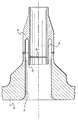
ここで添付図面の特に図1を参照すると、原子炉(その容器壁を符号12で示す。)用の炉心スプレーノズル(全体を符号10で示す。)が示されている。図1の炉心スプレーノズル10は、容器外部の炉心スプレー配管からノズル安全端14及び容器壁12を通して容器壁内部の炉心スプレー配管に冷却水を輸送するための従前用いられていた熱スリーブ部を交換した後のノズルを示している。さらに具体的には、図2を参照して後述するTボックス54及び熱スリーブ56が、図1に示すTボックス/熱スリーブアセンブリ16によって容器壁内部から交換されている。この交換アセンブリは、ノズル腔15内のノズル安全端14と機械的に連結している。図示した通り、容器壁12は炉心スプレーノズル10の一部として側方突出管18を含んでおり、この側方突出管18にはノズル安全端14が溶接されている。ノズル安全端14は、それまでノズル10内に存在していた熱スリーブの残部である円筒管つまり熱スリーブ残部20を含んでいる。
【0011】
具体的には、Tボックス/熱スリーブアセンブリは、最終組立て時に容器壁12の内面付近に位置するT継手又はTボックス22を含んでいる。Tボックスは、Tボックスから互いに反対方向に容器壁の内面に沿って約90°にわたって延在する配管に連結される1対の横方向通路24を含んでいる。この配管が炉心スプレーノズル10を通して供給される冷却水を炉心スプレー系の内部配管系へとつなぐものであることはいうまでもない。Tボックス22は口径の小さい交換熱スリーブ26へと狭まっていて、ノズル腔内のカウンタボア28の外端を終端とする。熱スリーブ26はその内壁面に、軸方向に離隔した口径の異なるねじ部30及び32を含んでいる。熱スリーブ26は、熱スリーブ残部20の端部をカウンタボア28内に受入れる寸法とされる。交換熱スリーブ26と熱スリーブ残部20の相対する端部の間に封止部材34(好ましくは皿ばね)を配置して、この封止部材若しくは皿ばね34を圧縮し、熱スリーブ残部20と交換熱スリーブ26の一部が圧されるようにしておく。
【0012】
熱スリーブ26を熱スリーブ残部20に機械的に結合しておくため、熱スリーブ残部20の端から後ろにさがった位置の内壁面に溝36(図3及び図4)が設けられる。一端付近に複数のフィンガ40を有していてもう一方の端付近に雄ねじ部42を有する円筒スリーブからなるコレット38が、交換熱スリーブ26内のねじ部30にねじ込まれる。フィンガ40の端に設けられた半径方向フランジ44が溝36に係合して、Tボックス/熱スリーブアセンブリ16が熱スリーブ残部20に機械的に取り付けられた状態に維持されることが理解されよう。
【0013】
フィンガ40のフランジ44を溝36と係合した状態に保つため、一端に雄ねじを有する保持スリーブ46がコレット38内に収容されている。交換熱スリーブ26のねじ部山32に保持スリーブ46をねじ込むことによって、保持スリーブ46のもう一方の端がフィンガ40に被さって、フィンガフランジ44が溝36から外れなくなることが理解されよう。Tボックス22の開放端にはカバー50が取り付けられ、カバーとTボックス端の間には封止部材(好ましくは皿ばね52)を配置される。
【0014】
コレット38は好ましくはインコネルで作られる。インコネルは鋼よりも線膨張率が小さい。熱スリーブ残部20と交換熱スリーブ26は鋼で作られる。従って、系が加熱されても、コレットは熱スリーブ残部20及び交換熱スリーブ26ほど膨張しない。皿ばね(若しくはベルビルワッシャ)34もインコネルで作られる。そうすると、高温で皿ばね34はさらに圧縮された状態におかれて封止性能が向上するとともに、部材間の熱膨張率の差に順応することで高温での熱適応性が得られる。
【0015】
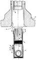
次に図2〜図5を参照して、既存のTボックス/熱スリーブをTボックス/熱スリーブアセンブリ16と交換する方法について説明する。まず、図2及び図3に示す通り、慣用の水中放電加工を用いて、炉心スプレーノズルから既存のTボックス54と熱スリーブ56の一部とを除去して、熱スリーブの残留端部58(図3)が残るようにする。この作業は水中で原子炉容器の内部から行われる。次に、熱スリーブ残部の新たな切断端部58に、交換Tボックス/熱スリーブ鍛造品と対合させるための前処理を施す。まず、熱スリーブ残部20の端部を平坦かつ熱スリーブ内腔と垂直に機械加工する。さらに、端部58から所定距離のところで熱スリーブ残部20の内面に環状溝36を機械加工によって形成する。明らかに、溝36はコレットのフィンガフランジ44とかみ合って、熱スリーブ残部20と交換Tボックス/熱スリーブアセンブリ16との間に機械的継手を形成するが、この継手は両者間の軸方向荷重に十分に耐える。次に、コレット38を交換Tボックス/熱スリーブアセンブリにねじ込む。コレット38と熱スリーブ26とをねじ部30でのねじ込み式としたことで、Tボックス/熱スリーブ端部と熱スリーブ残部の端部58との封止境界とコレットフィンガ40との間の長さが調整できることが理解されよう。封止部材(好ましくは皿ばね60)を交換熱スリーブ26の端に配置して、交換熱スリーブ26のカウンタボア28に熱スリーブ残部の端部58が収まるようにアセンブリ全体を原子炉容器12の内部からノズル腔12に挿入する。皿ばね60は熱スリーブ残部20と交換熱スリーブ26の相対する端面間に置かれる。また、熱スリーブ残部20の端部58が収まるように交換熱スリーブ26を挿入すると、フィンガ40のフランジ44が溝36と係合して機械的に集合状態に保つ。皿ばね60は、熱スリーブ残部20及び交換熱スリーブ26の各部分に圧縮荷重を及ぼす。
【0016】
交換熱スリーブ26と熱スリーブ残部20とを機械的係合状態に保つため、Tボックスの開放端を通して保持スリーブ46を挿入して、交換熱スリーブ26のねじ部32にねじ込む。保持スリーブ46の端が前に進んでフィンガ40の内面に被さってフィンガのフランジ44が溝36内に保持されることが理解されよう。フィンガ40を熱スリーブ残部20の端部の中に挿入し易くするため、フィンガ40の端部にはテーパが付けられている。こうして、フィンガ40は最初は熱スリーブ残部20の内面に沿って進むことができるように半径方向内側に撓み、次いで半径方向外側に跳ね返ってフランジ44が溝36内に係合する。保持スリーブ46は、スパナレンチその他適当な工具を用いて所定位置まで回転して挿入し、不慮の回転及び脱落を防止するため、例えば交換熱スリーブ26にかしめるなどして、回転しないようにロックする。
【0017】
上記Tボックス/熱スリーブ交換アセンブリ16は、3〜4個の等間隔に配置された調整可能なウェッジブロック62によってノズル腔内に支持される。各ウェッジブロック62は、留め具64、ウェッジ66及びジャッキねじ68からなる。ウェッジを推すためのジャッキねじを適切に調整することによって、挿入アセンブリを熱スリーブ残部20に対して心合わせすることができる。こうして、ウェッジブロックはアセンブリと熱スリーブとを軸方向に整列した状態に維持して、コレットのフィンガの曲げ応力を最小限に抑える。また、ウェッジブロック62の使用によって、炉心スプレーノズル10内での適切な据付を確保するための現場での測定や機械加工が必要なくなる。最後に、Tボックスの開放端にキャップ若しくはカバー50をねじ込む。キャップとTボックスの間には別の皿ばね封止リング52を配置するのが好ましい。封止端キャップ50のゆるみを防ぐため、端キャップ50とTボックス22の間に回転防止構造を導入してもよい。
【0018】
以上、本発明を現時点で最も実用的で好ましいと思料される実施形態について説明してきたが、本発明は、開示した実施形態のみに限定されるものではなく、請求項に記載された技術的思想及び技術的範囲に属する様々な修正及び均等な構成にも及ぶものである。
【図面の簡単な説明】
【図1】 本発明の好ましい実施形態に従って交換した炉心スプレーノズル内の炉心スプレーTボックス及び熱スリーブの部分断面図。
【図2】 図1と同様の図であるが、交換前のノズル及び熱スリーブを示す。
【図3】 図2の熱スリーブを交換Tボックス/熱スリーブアセンブリで交換するための一連の工程の一つを示す。
【図4】 図2の熱スリーブを交換Tボックス/熱スリーブアセンブリで交換するための一連の工程の一つを示す。
【図5】 図2の熱スリーブを交換Tボックス/熱スリーブアセンブリで交換するための一連の工程の一つを示す。
【符号の説明】
10 ノズル
12 原子炉容器壁
14 ノズル安全端
15 ノズル腔
20 熱スリーブ残部
22 Tボックス若しくはT継手
26 交換熱スリーブ
34 封止部材または皿ばねまたはベルビルワッシャ
36 溝
38 コレット
40 フィンガ
44 フランジ
46 保持スリーブ
50 カバー
52 皿ばね封止リング
54 Tボックス
56 熱スリーブ
58 端部[0001]
BACKGROUND OF THE INVENTION
The present invention relates to an apparatus and method for exchanging a core spray T-box and a thermal sleeve that form part of a core spray system in a nuclear reactor, and more specifically, a T-box from the inside of a reactor vessel. And replacement of a portion of the thermal sleeve.
[0002]
[Prior art]
In a typical boiling water reactor, a core spray system is provided to prevent the fuel cladding temperature from rising excessively by supplying coolant to the reactor core in the event of a loss of coolant. ing. A core spray system typically includes a core spray pump that delivers water through an external piping system in communication with a nozzle that penetrates the reactor vessel wall. Inside the reactor vessel, the nozzle surrounds a thermal sleeve, and at the end of the thermal sleeve is a T-joint or T-box for supplying cooling water to the reactor core via an internal piping / nozzle system. Typically a pair of redundant systems are used, each including a core spray nozzle having a nozzle cavity extending through the vessel wall and a nozzle safety end outside the vessel wall for connection to a core spray pipe outside the vessel wall. . A T-box is present inside the container wall and is welded to the thermal sleeve within the nozzle cavity, and the thermal sleeve itself is welded to the nozzle safety end.
[Patent Document 1]
U.S. Pat.No. 3,138,534 Published June 1964
[Patent Document 2]
U.S. Pat. No. 3,383,287 Published May 1968
[Patent Document 3]
U.S. Pat.No. 3613936 published October 1971
[Patent Document 4]
U.S. Patent No. 3895831 Published July 1975
[Patent Document 5]
U.S. Patent No. 4032398 published in June 1977
[Patent Document 6]
U.S. Pat. No. 4,168,071 published in September 1979
[Patent Document 7]
U.S. Pat. No. 4,198272 Published April 1980
[Patent Document 8]
U.S. Pat.No. 4,285770 Published August 1981
[Patent Document 9]
U.S. Pat.No. 4,356,147 published October 1982
[Patent Document 10]
U.S. Pat.No. 4,369,893 Published January 1983
[Patent Document 11]
U.S. Pat.No. 4,576,400 published in March 1986
[Patent Document 12]
U.S. Patent No. 4693389, published in September 1987
[Patent Document 13]
U.S. Pat. No. 4,834,935 published May 1989
[Patent Document 14]
U.S. Pat.No. 5,345,484 published in September 1994
[Patent Document 15]
US Pat. No. 5,737,380 Published April 1998
[Patent Document 16]
U.S. Pat. No. 5,785361 Published July 1998
[Patent Document 17]
US Patent No. 5839192 Published November 1998
[Patent Document 18]
U.S. Patent No. 5901192 published in May 1999
[Patent Document 19]
U.S. Patent No. 5912936 published in June 1999
[Patent Document 20]
U.S. Patent No. 5918911 published July 1999
[Patent Document 21]
U.S. Patent No. 5947529 Published September 1999
[Patent Document 22]
US Patent No. 6201847 published in March 2001
[Patent Document 23]
German Patent No. 2829590 Published in January 1980 [0003]
[Problems to be solved by the invention]
These welded joints are prone to cracking. If cracks occur in one or more welds, the soundness of the container wall is impaired. Although it is possible to remove the safety end of the nozzle from a position outside the reactor vessel wall, the reactor vessel drainage is unavoidable for external safety end removal, so an unacceptable long-term shutdown It should be time consuming and expensive. Therefore, it is possible to use the T box and the thermal sleeve without replacing the attached safety end and replacing it, and to maintain the integrity of the reactor vessel wall, There is a need to provide a simple and reliable coupling device between the safety end of the nozzle.
[0004]
[Means for Solving the Problems]
In accordance with a preferred embodiment of the present invention, an apparatus and method are provided for mechanically attaching a replacement T-box and thermal sleeve portion from the interior of a reactor vessel to the safety end of an existing core spray nozzle. In order to achieve the above objective from the inside of the reactor vessel wall, the existing or existing T-box and part of the thermal sleeve are first removed from the core spray nozzle. This is done by conventional underwater electrical discharge machining (EDM). Once a portion of the existing thermal sleeve has been removed, the cut end of the remaining thermal sleeve is machined flat and perpendicular to the nozzle cavity to mate with an exchange assembly that combines the T-box and the thermal sleeve. To. An annular groove is also machined at the end of the remaining thermal sleeve, preferably along the inner surface of the remaining thermal sleeve. The replacement T-box / thermal sleeve assembly is then inserted into the nozzle cavity and mechanically secured to the remaining thermal sleeve. Thus, the present invention is implemented from the inside of the reactor vessel.
[0005]
A sealing member (preferably a disc spring) is inserted between the abutting ends of the exchange heat sleeve and the remaining heat sleeve so that the exchange heat sleeve and the remaining heat sleeve are pressed during final assembly. In order to mechanically secure the replacement T-box / thermal sleeve assembly within the nozzle cavity, a collet having a plurality of circumferentially spaced fingers with radial flanges at the ends is provided at the end opposite the flange. To the assembly (preferably pushed in). This allows the length of the collet fingers to be adjusted relative to the replacement heat sleeve in securing the replacement heat sleeve within the nozzle. For example, the collet may be screwed into the exchange heat sleeve. As the replacement T-box / thermal sleeve assembly and washer are inserted into the nozzle cavity, the collet flange advances through the end of the remaining thermal sleeve and engages the groove. By adjusting the relative position of the collet and the exchange heat sleeve (with the depth of screwing), not only is the disc spring compressed when the exchange heat sleeve and the rest of the heat sleeve are fitted, but the exchange heat sleeve and A part of the remaining portion of the thermal sleeve is also placed in a compressed state.
[0006]
In order to fix the finger flange in the groove, the holding sleeve is also screwed into the replacement heat sleeve so that the holding sleeve is placed over the finger, and the finger flange is radially away from the groove when it is finally fixed (i.e., the radius To prevent movement inward). Once the collet finger flange is locked in the groove, the holding sleeve is crimped onto the replacement heat sleeve to prevent the replacement heat sleeve from coming off due to relative rotation.
[0007]
In addition, a plurality of adjustable wedges are disposed between the exchange heat sleeve and the nozzle cavity near the inner wall of the reactor vessel. By adjusting the wedge, the exchange heat sleeve is axially centered within the nozzle cavity. The wedge supports the weight of the replacement T-box / thermal sleeve assembly from the container wall, thereby minimizing bending stress on the collet fingers. The end cover is then screwed into the open end of the T box housing to compress the second disc spring sealing ring between the cover and the housing. In order to finally fix the cover and the T box to each other, an anti-rotation structure such as caulking may be used.
[0008]
According to a preferred embodiment of the present invention, there is provided a connection device between a reactor vessel wall and a pipe inside the reactor vessel in a reactor having a nozzle penetrating a wall surface for supplying fluid into the reactor, The nozzle includes an end portion of a sleeve therein and has a groove, and the connecting device is a thermal sleeve extending from the inside of the reactor vessel wall, and the sleeve end portion inside the nozzle A generally cylindrical collet having a plurality of circumferentially spaced fingers with a radial flange engaging one end thereof and a radial flange engaging one end of the groove, opposite the one end of the collet A collet connected to the thermal sleeve near the end on the side, and a holding sleeve fixed to the thermal sleeve and extending along the finger to hold the flange in the groove. Apparatus is provided.
[0009]
According to another preferred embodiment of the present invention, in a nuclear reactor including a reactor vessel wall and a nozzle that penetrates the reactor vessel wall to supply fluid into the reactor, the joint and heat from the inside of the reactor vessel wall. A method for replacing a portion of a sleeve, wherein the nozzle includes a nozzle cavity and a nozzle safety end having a thermal sleeve in the nozzle cavity, the thermal sleeve being near the inner surface of the reactor vessel wall. A step of removing a portion of the joint and the thermal sleeve from within the nozzle, leaving the thermal sleeve remaining in the nozzle, wherein the method is performed from the inside of the reactor vessel wall; Forming a groove in the remaining thermal sleeve in the nozzle cavity, inserting a replacement thermal sleeve into the nozzle cavity from inside the reactor vessel, and engaging the end of the replacement thermal sleeve with the end of the remaining thermal sleeve And exchange The spaced fingers in the circumferential direction of the fixed collet sleeve is engaged with the above grooves, a method is provided comprising the step of coupling together the replacement thermal sleeve and the thermal sleeve balance.
[0010]
DETAILED DESCRIPTION OF THE INVENTION
Referring now specifically to FIG. 1 of the accompanying drawings, there is shown a core spray nozzle (generally indicated by reference numeral 10) for a nuclear reactor (whose container wall is indicated by reference numeral 12). The core spray nozzle 10 of FIG. 1 replaces the previously used thermal sleeve for transporting cooling water from the core spray piping outside the vessel through the
[0011]
Specifically, the T-box / thermal sleeve assembly includes a T-joint or T-
[0012]
In order to mechanically couple the
[0013]
In order to keep the flange 44 of the
[0014]
The
[0015]
A method of replacing an existing T box / thermal sleeve with a T box / thermal sleeve assembly 16 will now be described with reference to FIGS. First, as shown in FIGS. 2 and 3, the existing
[0016]
In order to keep the
[0017]
The T-box / thermal sleeve exchange assembly 16 is supported in the nozzle cavity by 3-4 equally spaced adjustable wedge blocks 62. Each
[0018]
Although the present invention has been described above with respect to embodiments that are considered to be the most practical and preferred at the present time, the present invention is not limited to only the disclosed embodiments, but the technical idea described in the claims. And various modifications and equivalent configurations belonging to the technical scope.
[Brief description of the drawings]
FIG. 1 is a partial cross-sectional view of a core spray T box and thermal sleeve in a core spray nozzle replaced in accordance with a preferred embodiment of the present invention.
2 is a view similar to FIG. 1, but showing the nozzle and thermal sleeve before replacement.
FIG. 3 illustrates one of a series of steps for replacing the thermal sleeve of FIG. 2 with a replacement T-box / thermal sleeve assembly.
4 illustrates one of a series of steps for replacing the thermal sleeve of FIG. 2 with a replacement T-box / thermal sleeve assembly.
FIG. 5 illustrates one of a series of steps for replacing the thermal sleeve of FIG. 2 with a replacement T-box / thermal sleeve assembly.
[Explanation of symbols]
10
Claims (16)
上記ノズル(10)は、その内部に、端部(58)を有するノズル側スリーブ(20)を有し、このノズル側スリーブ(20)はその壁面に溝(36)が形成されており、
当該連結装置は、
前記原子炉容器壁(12)の内部から延在し、前記ノズル側スリーブ(20)の前記端部(58)と隣接する端部を有する延長熱スリーブ(26)と、
前記ノズル側スリーブ(20)に形成された前記溝(36)に係合するために、半径方向に突出するフランジ(44)を一端に有する複数のフィンガ(40)が円周方向に互いに離隔されて配置された概略円筒形のコレット(38)であって、上記コレット(38)の一端と反対側端の両端部付近において前記延長熱スリーブ(26)と連結されてなるコレット(38)と、
前記延長熱スリーブ(26)に固定され前記フィンガ(40)に沿って延在し、これにより、上記フランジ(44)を前記溝(36)に保持させる保持スリーブ(46)と、
を含んでなることを特徴とする連結装置。 Oite reactor having a nozzle (10) penetrating the reactor vessel walls (12) for supplying fluid to the reactor, the nozzle (10) and the reactor vessel inside the pipe and coupling device for connecting Because
The nozzle (10) has a nozzle side sleeve (20) having an end portion (58) therein, and the nozzle side sleeve (20) has a groove (36) formed on the wall surface thereof .
The connecting device is
Extend from the interior of the reactor vessel wall (12), the extension thermal sleeve (26) having said end edge portion adjacent to the (58) of the nozzle-side sleeve (20),
In order to engage with the groove (36) formed in the nozzle side sleeve (20), a plurality of fingers (40) having flanges (44) projecting in the radial direction at one end are spaced apart from each other in the circumferential direction. a arranged Te a generally cylindrical collet (38), the collet one end and the opposite end collet consisting coupled with the extension thermal sleeve (26) in the vicinity of both ends of the (38) (38) ,
Secured to said extended thermal sleeve (26) extending along said finger (40), by which a retaining sleeve which makes holding the flange (44) in said groove (36) (46),
A coupling device comprising:
前記コレット(38)の前記フランジ(44)が前記溝(36)と係合するように概略半径方向外側に突出していて、前記コレット(38)と前記延長熱スリーブ(26)が、このコレット(38)の前記反対側端部で互いにねじ込み結合しており、
前記保持スリーブ(46)が前記フィンガ(40)の半径方向内面に被さり、前記保持スリーブ(46)が前記延長熱スリーブ(26)にねじ込まれていて、かつ前記ノズル側スリーブ(20)の前記端部(58)と該ノズル側スリーブ端部(58)に隣接する前記延長熱スリーブ(26)の前記端部との間に封止ワッシャー(34)をさらに含む、
ことを特徴とする請求項1記載の連結装置。The groove (36) is present on the radially inner surface of the end (58) of the nozzle side sleeve (20) ;
Said flange (44) is not projecting generally radial outward to engage with the groove (36) of said collet (38), the collet (38) and the extension thermal sleeve (26) is, the collet ( 38) and screwed together at the opposite ends.
Radially overlies the inner surface, and the retaining sleeve (46) has been screwed the extension thermal sleeve (26), and said end of said nozzle side sleeve (20) of said holding sleeve (46) said fingers (40) A sealing washer (34) between the portion (58) and the end of the extended thermal sleeve (26) adjacent to the nozzle side sleeve end (58) ;
The connecting device according to claim 1.
前記原子炉容器壁(12)の内部から前記継手(54)と被交換の前記熱スリーブ(56)を交換する方法であって、当該方法が、
前記原子炉容器壁(12)の内側から行われる除去工程であって、前記ノズル(10)内から前記継手(54)と前記被交換熱スリーブ(56)の一部を除去することにより前記ノズル(10)内に残りのスリーブ残部(20)を残す除去工程と、
前記ノズル腔(15)内に残った前記スリーブ残部(20)の壁面に溝(36)を形成する工程と、
一部が除去される前記被交換熱スリーブ(56)と交換可能な形状を有する交換用熱スリーブ(26)を前もって準備する工程であって、互いに円周方向に離隔して配置され各々が前記被交換熱スリーブ(56)の軸方向に伸びる複数のフィンガ(40)を設けられたコレット(38)を前記交換用熱スリーブ(26)に固定して準備する工程と、
前もって準備したコレット付き交換用熱スリーブ(26)を前記原子炉容器の内部から前記ノズル腔(15)内に挿入する工程と、
前記交換用熱スリーブ(26)の先端端部を前記スリーブ残部(20)の除去側に形成された端部(58)と係合させる工程と、
前記交換用熱スリーブ(26)に固定された前記コレット(38)の前記フィンガ(40)を、前記スリーブ残部(20)に形成された前記溝(36)に係合させて、前記交換用熱スリーブ(26)と前記スリーブ残部(20)を互いに結合する工程と、
を含んでなるスリーブ交換方法。In a nuclear reactor having a nozzle (10) passing through a reactor vessel wall (12) for supplying fluid into the nuclear reactor, the nozzle (10) includes a nozzle cavity (15) and the nozzle cavity (15). in reactor configurations including a nozzle safety end (14) having a fitting (54) coupled thermal sleeve (56) in the vicinity of the inner surface of the said reactor vessel walls (12) at the inner,
A method for replacing the joint (54) and the heat sleeve of the exchange (56) from the interior of the reactor vessel wall (12), the method comprising
A removing step is performed from the inside of the reactor vessel wall (12), the nozzle by removing a portion of said fitting (54) and said replacement target thermal sleeve (56) from said nozzle (10) (10) a removal step of leaving the remaining sleeve remainder (20 ) in the interior;
Forming a groove (36) on the wall of the sleeve balance remaining on the nozzle bore (15) in (20),
A step of preparing in advance a replacement heat sleeve (26) having a shape replaceable with the exchanged heat sleeve (56) from which a part is removed, each being arranged circumferentially spaced apart from each other Fixing the collet (38) provided with a plurality of fingers (40) extending in the axial direction of the exchanged heat sleeve (56) to the exchange heat sleeve (26);
A step of inserting into said nozzle cavity (15) prepared in advance was replaced heat sleeved collet (26) from the interior of the reactor vessel,
A step of engaging an end portion which is formed on the removal side of the distal end of the sleeve rest (20) and (58) of said replacement thermal sleeve (26),
Wherein said finger (40) of the replacement thermal sleeve the collet which is fixed to (26) (38), is engaged with the sleeve remainder (20) which is formed on the groove (36), said replacement thermal a step of coupling together the sleeve (26) and said sleeve remainder (20),
A sleeve replacement method comprising:
Applications Claiming Priority (2)
| Application Number | Priority Date | Filing Date | Title |
|---|---|---|---|
| US09/443,374 US6345084B1 (en) | 1999-11-19 | 1999-11-19 | Apparatus and methods for replacing a core spray T-box/thermal sleeve in a nuclear reactor |
| US09/443374 | 1999-11-19 |
Publications (3)
| Publication Number | Publication Date |
|---|---|
| JP2001201588A JP2001201588A (en) | 2001-07-27 |
| JP2001201588A5 JP2001201588A5 (en) | 2008-01-10 |
| JP4520017B2 true JP4520017B2 (en) | 2010-08-04 |
Family
ID=23760543
Family Applications (1)
| Application Number | Title | Priority Date | Filing Date |
|---|---|---|---|
| JP2000350341A Expired - Fee Related JP4520017B2 (en) | 1999-11-19 | 2000-11-17 | Reactor thermal sleeve repair and replacement coupling device and replacement method |
Country Status (6)
| Country | Link |
|---|---|
| US (1) | US6345084B1 (en) |
| JP (1) | JP4520017B2 (en) |
| CH (1) | CH694930A5 (en) |
| ES (1) | ES2168994B2 (en) |
| MX (1) | MXPA00011374A (en) |
| TW (1) | TW498347B (en) |
Families Citing this family (24)
| Publication number | Priority date | Publication date | Assignee | Title |
|---|---|---|---|---|
| US6421406B1 (en) * | 2001-03-12 | 2002-07-16 | General Electric Company | Core spray upper T-box to safe end attachment |
| US6587535B1 (en) * | 2001-07-10 | 2003-07-01 | General Electric Company | Jet pump slip joint labyrinth seal method |
| US20050135537A1 (en) * | 2002-10-01 | 2005-06-23 | Bruce Hinton | Pressure vessel |
| US7203263B2 (en) * | 2004-07-26 | 2007-04-10 | General Electric Company | Core spray apparatus and method for installing the same |
| ITMI20050847A1 (en) * | 2005-05-11 | 2006-11-12 | Olmi Spa | JUNCTION BETWEEN COOLED TUBE AND NON-COOLED HOSE IN A DOUBLE PIPE HEAT EXCHANGER |
| EP2092532A4 (en) * | 2006-12-14 | 2012-08-01 | Westinghouse Electric Sweden | Jet pump riser clamp |
| EP2097664B1 (en) * | 2006-12-21 | 2014-03-19 | Westinghouse Electric Sweden AB | A mechanical assembly for securing the structural integrity of a pipe joint |
| US7963566B2 (en) * | 2007-11-15 | 2011-06-21 | Ge-Hitachi Nuclear Energy Americas Llc | Apparatus and method for repairing a core spray line pipe weld joint |
| US7963568B2 (en) * | 2007-11-16 | 2011-06-21 | GE-Hitachi Nuclear Energy Americans LLC | Apparatus and method for repairing a core spray line elbow weld joint |
| KR101067065B1 (en) * | 2009-12-14 | 2011-09-22 | 한전케이피에스 주식회사 | Removal device for reactor coolant system cold leg side of thermal sleeve |
| KR101067232B1 (en) * | 2009-12-14 | 2011-09-22 | 한전케이피에스 주식회사 | Removal method for reactor coolant system cold leg side of thermal sleeve |
| US8681922B2 (en) * | 2010-01-13 | 2014-03-25 | Westinghouse Electric Company Llc | Pressurizer with a mechanically attached surge nozzle thermal sleeve |
| US8599992B2 (en) * | 2010-12-30 | 2013-12-03 | Ge-Hitachi Nuclear Energy Americas, Llc | Method and apparatus for a jet pump inlet mixer integral slip joint clamp |
| JP5859344B2 (en) * | 2012-03-05 | 2016-02-10 | 三菱重工業株式会社 | Thermal sleeve repair method |
| US9400112B2 (en) | 2013-12-13 | 2016-07-26 | General Electric Company | Method for disassembling a bundled tube fuel injector |
| US9423134B2 (en) | 2013-12-13 | 2016-08-23 | General Electric Company | Bundled tube fuel injector with a multi-configuration tube tip |
| US9638227B2 (en) | 2014-02-20 | 2017-05-02 | GE-Hitachi Nuclear Energry Americas LLC | Apparatuses and methods for structurally replacing cracked welds in nuclear power plants |
| US9180557B1 (en) * | 2014-04-21 | 2015-11-10 | Areva Inc. | Two-piece replacement nozzle |
| CN106855156A (en) * | 2017-01-20 | 2017-06-16 | 中广核研究院有限公司 | double-layer sleeve structure and nuclear reactor |
| US11501887B2 (en) * | 2018-02-12 | 2022-11-15 | Westinghouse Electric Company Llc | Replacement thermal sleeve for a reactor vessel closure head penetration adapter of control rod drive mechanism |
| JP7148631B2 (en) * | 2018-04-13 | 2022-10-05 | フラマトム インコーポレイテッド | Method and apparatus for replacing sleeves lining reactor pressure vessel tubes |
| US11014114B2 (en) * | 2018-07-25 | 2021-05-25 | Westinghouse Electric Company Llc | Feedwater sparger repair |
| WO2021015732A1 (en) * | 2019-07-22 | 2021-01-28 | Framatome Inc. | Method and device for replacing sleeves lining nuclear reactor pressure vessel tubes from the lower end |
| US11380447B2 (en) | 2020-05-26 | 2022-07-05 | Westinghouse Electric Company Llc | Method for installing extension tube in a nuclear reactor |
Citations (2)
| Publication number | Priority date | Publication date | Assignee | Title |
|---|---|---|---|---|
| US3613936A (en) * | 1970-04-20 | 1971-10-19 | Arthur E Kaiser | Adjustable diameter pipe closure plug |
| US3895831A (en) * | 1973-05-10 | 1975-07-22 | Conax Corp | Seal assembly providing dual seal zones |
Family Cites Families (27)
| Publication number | Priority date | Publication date | Assignee | Title |
|---|---|---|---|---|
| US3138534A (en) * | 1960-09-06 | 1964-06-23 | Westinghouse Electric Corp | Fuel arrangement for a neutronic test reactor |
| GB1106256A (en) * | 1965-06-15 | 1968-03-13 | Atomic Energy Authority Uk | Improvements relating to nuclear reactors |
| JPS5225518B2 (en) * | 1974-03-15 | 1977-07-08 | ||
| GB1518292A (en) * | 1975-05-07 | 1978-07-19 | Atomic Energy Authority Uk | Nuclear reactor fuel sub-assemblies |
| GB1582192A (en) * | 1977-06-03 | 1980-12-31 | Nuclear Power Co Ltd | Fuel sub-assemblies for nuclear reactors |
| SE410667B (en) * | 1978-03-08 | 1979-10-22 | Asea Atom Ab | DEVICE FOR FEEDING COLD WATER IN A NUCLEAR REACTOR TANK |
| US4168071A (en) * | 1978-03-17 | 1979-09-18 | General Electric Company | Thermal isolator |
| DE2829590C3 (en) * | 1978-07-05 | 1981-02-05 | Kraftwerk Union Ag, 4330 Muelheim | Reactor pressure vessel for a boiling water reactor |
| JPS5536631A (en) * | 1978-09-06 | 1980-03-14 | Hitachi Ltd | Fluid nozzle with heat insulating plate |
| US4285770A (en) * | 1979-07-12 | 1981-08-25 | General Electric Company | Jet pump with labyrinth seal |
| JPS5614998A (en) * | 1979-07-19 | 1981-02-13 | Tokyo Shibaura Electric Co | Nozzle |
| US4369893A (en) * | 1981-02-19 | 1983-01-25 | The United States Of America As Represented By The United States Department Of Energy | Sealing arrangement with annular flexible disc |
| US4576400A (en) * | 1984-02-10 | 1986-03-18 | Allred Von D | Riser repair assembly for underground irrigation systems |
| JPS60176196U (en) * | 1984-04-28 | 1985-11-21 | 石川島播磨重工業株式会社 | Thermal sleeves for nuclear pressure vessels, etc. |
| JPS6180094A (en) * | 1984-09-28 | 1986-04-23 | 株式会社日立製作所 | Wedling thermal sleeve |
| US4834935A (en) * | 1984-12-24 | 1989-05-30 | Combustion Engineering, Inc. | Feedwater sparger assembly |
| US4693389A (en) * | 1986-01-31 | 1987-09-15 | The Babcock & Wilcox Company | Reactor internals core barrel hole plug |
| US5345484A (en) * | 1993-05-03 | 1994-09-06 | General Electric Company | Feedwater nozzle and method of repair |
| US5605361A (en) * | 1994-05-06 | 1997-02-25 | Entergy Operations, Inc. | Replacement nozzle for pressure vessels and method of a attaching same |
| US5785361A (en) * | 1996-03-21 | 1998-07-28 | General Electric Company | Feedwater nozzle thermal sleeve |
| US5737380A (en) * | 1996-07-29 | 1998-04-07 | General Electric Company | Core spray line assembly |
| US5839192A (en) * | 1996-11-27 | 1998-11-24 | Mpr Associates, Inc. | Method and apparatus for repairing cracked core spray supply piping in a boiling water reactor |
| JP3767077B2 (en) * | 1997-04-15 | 2006-04-19 | 石川島播磨重工業株式会社 | Reactor pressure vessel water supply nozzle safe end replacement method and replacement structure |
| US5912936A (en) * | 1997-08-11 | 1999-06-15 | General Electric Company | Pipe connector assembly |
| US5901192A (en) * | 1997-10-03 | 1999-05-04 | General Electric Company | Core spray line riser apparatus and methods |
| US5947529A (en) * | 1998-06-08 | 1999-09-07 | General Electric Company | Core spray line coupling apparatus |
| US6201847B1 (en) * | 1998-10-22 | 2001-03-13 | General Electric Company | Core spray upper T-box to reactor vessel attachment |
-
1999
- 1999-11-19 US US09/443,374 patent/US6345084B1/en not_active Expired - Fee Related
-
2000
- 2000-11-02 ES ES200002629A patent/ES2168994B2/en not_active Expired - Fee Related
- 2000-11-06 TW TW089123339A patent/TW498347B/en active
- 2000-11-14 CH CH02214/00A patent/CH694930A5/en not_active IP Right Cessation
- 2000-11-17 JP JP2000350341A patent/JP4520017B2/en not_active Expired - Fee Related
- 2000-11-17 MX MXPA00011374A patent/MXPA00011374A/en active IP Right Grant
Patent Citations (2)
| Publication number | Priority date | Publication date | Assignee | Title |
|---|---|---|---|---|
| US3613936A (en) * | 1970-04-20 | 1971-10-19 | Arthur E Kaiser | Adjustable diameter pipe closure plug |
| US3895831A (en) * | 1973-05-10 | 1975-07-22 | Conax Corp | Seal assembly providing dual seal zones |
Also Published As
| Publication number | Publication date |
|---|---|
| US6345084B1 (en) | 2002-02-05 |
| ES2168994A1 (en) | 2002-06-16 |
| MXPA00011374A (en) | 2002-05-23 |
| ES2168994B2 (en) | 2003-10-16 |
| TW498347B (en) | 2002-08-11 |
| JP2001201588A (en) | 2001-07-27 |
| CH694930A5 (en) | 2005-09-15 |
Similar Documents
| Publication | Publication Date | Title |
|---|---|---|
| JP4520017B2 (en) | Reactor thermal sleeve repair and replacement coupling device and replacement method | |
| JP5288767B2 (en) | Jet pump diffuser weld repair equipment | |
| US7798535B2 (en) | Pipe clamp | |
| US5839192A (en) | Method and apparatus for repairing cracked core spray supply piping in a boiling water reactor | |
| US8118528B2 (en) | Field replaceable hammer union wing nut apparatus and method | |
| US4723578A (en) | Steam generator tube repair method and assembly | |
| EP0164524A1 (en) | Boundary seal for vessel penetration | |
| US5205038A (en) | Method of replacing a tube on a straight-tube heat exchanger | |
| JP5588133B2 (en) | Method and apparatus for repair of core spray downcomer slip joint coupling | |
| EP2060839B1 (en) | Method and apparatus for repairing a core spray downcomer pipe in a nuclear reactor | |
| EP0962941A1 (en) | Core spray line coupling apparatus and methods | |
| US20080031395A1 (en) | Core spray apparatus and method for installing the same | |
| US6195892B1 (en) | Method for replacing cracked core spray supply piping in a boiling water reactor | |
| US5094801A (en) | Two piece pressurizer heater sleeve | |
| EP1307679A1 (en) | Pipe assembly | |
| EP0137984A2 (en) | Tube repair insert for steam generator | |
| KR101937610B1 (en) | Method for repairing nozzle of RCS pipe in reactor | |
| US20030031287A1 (en) | Seal arrangement for in-core instrument housing | |
| US6201847B1 (en) | Core spray upper T-box to reactor vessel attachment | |
| US6390509B1 (en) | Shroud connection for replacement core spray pipe | |
| US4568111A (en) | Detachable connection for a nuclear reactor fuel assembly | |
| US10902958B2 (en) | Mechanical seal assembly and method for sealing an opening in a nuclear power plant | |
| US6167618B1 (en) | Method for repairing vertical welds in a boiling water reactor shroud using a clamp with eccentric pins | |
| JPH01142301A (en) | Remote control type device for mounting/dismantling plug for closing tube of steam generator | |
| US4592391A (en) | Tube sleeve |
Legal Events
| Date | Code | Title | Description |
|---|---|---|---|
| A521 | Written amendment |
Free format text: JAPANESE INTERMEDIATE CODE: A523 Effective date: 20071115 |
|
| A621 | Written request for application examination |
Free format text: JAPANESE INTERMEDIATE CODE: A621 Effective date: 20071115 |
|
| A131 | Notification of reasons for refusal |
Free format text: JAPANESE INTERMEDIATE CODE: A131 Effective date: 20090929 |
|
| A601 | Written request for extension of time |
Free format text: JAPANESE INTERMEDIATE CODE: A601 Effective date: 20091228 |
|
| RD02 | Notification of acceptance of power of attorney |
Free format text: JAPANESE INTERMEDIATE CODE: A7422 Effective date: 20091228 |
|
| RD04 | Notification of resignation of power of attorney |
Free format text: JAPANESE INTERMEDIATE CODE: A7424 Effective date: 20091228 |
|
| A602 | Written permission of extension of time |
Free format text: JAPANESE INTERMEDIATE CODE: A602 Effective date: 20100107 |
|
| A521 | Written amendment |
Free format text: JAPANESE INTERMEDIATE CODE: A523 Effective date: 20100329 |
|
| TRDD | Decision of grant or rejection written | ||
| A01 | Written decision to grant a patent or to grant a registration (utility model) |
Free format text: JAPANESE INTERMEDIATE CODE: A01 Effective date: 20100420 |
|
| A01 | Written decision to grant a patent or to grant a registration (utility model) |
Free format text: JAPANESE INTERMEDIATE CODE: A01 |
|
| A61 | First payment of annual fees (during grant procedure) |
Free format text: JAPANESE INTERMEDIATE CODE: A61 Effective date: 20100520 |
|
| FPAY | Renewal fee payment (event date is renewal date of database) |
Free format text: PAYMENT UNTIL: 20130528 Year of fee payment: 3 |
|
| R150 | Certificate of patent or registration of utility model |
Free format text: JAPANESE INTERMEDIATE CODE: R150 |
|
| LAPS | Cancellation because of no payment of annual fees |