JP4518552B2 - High frequency coaxial cable - Google Patents
High frequency coaxial cable Download PDFInfo
- Publication number
- JP4518552B2 JP4518552B2 JP2004302955A JP2004302955A JP4518552B2 JP 4518552 B2 JP4518552 B2 JP 4518552B2 JP 2004302955 A JP2004302955 A JP 2004302955A JP 2004302955 A JP2004302955 A JP 2004302955A JP 4518552 B2 JP4518552 B2 JP 4518552B2
- Authority
- JP
- Japan
- Prior art keywords
- layer
- coaxial cable
- frequency coaxial
- foaming
- outer layer
- Prior art date
- Legal status (The legal status is an assumption and is not a legal conclusion. Google has not performed a legal analysis and makes no representation as to the accuracy of the status listed.)
- Expired - Fee Related
Links
Images
Landscapes
- Communication Cables (AREA)
- Waveguides (AREA)
Description
本発明は、高発泡度の絶縁体層を有する高周波同軸ケーブルに関するものである。 The present invention relates to a high-frequency coaxial cable having a highly foamed insulator layer.
高周波用の発泡同軸ケーブルは、銅からなる中心導体とその上に設けられる発泡絶縁体層と、その外周に設けられる外部導体等から構成される。そして最近は、周波数域がGHz帯域においても減衰量が小さい発泡同軸ケーブルが要求されるため、高発泡度の絶縁体層が望まれている。このため前記発泡絶縁体層は、内部導体上にポリエチレン、ポリプロピレン、ポリスチレンやフッ素樹脂等の薄肉充実体からなる内層を形成し、その上に前記樹脂からなる発泡させる中間層を形成し、さらに前述の樹脂からなる充実体の外層を構成することによって、絶縁体層の発泡度を向上させるようにしている。このような構造の発泡した絶縁体層は、発泡度が80%程度のものも報告されている。しかしながら、このような高発泡度の同軸ケーブルを安定して製造することは、実際には簡単ではなかった。例えば特許文献1に開示されている高発泡同軸ケーブルの製造方法においても、安定して高発泡の同軸ケーブルを得ることには問題があった。すなわち、発泡時に前記外層からガスが放出され易くなったり、連続気泡や巨大空泡が形成されたりするため、安定して高発泡の絶縁体層を得ることは難しかった。このような大きな空泡からなる発泡絶縁体層となると、同軸ケーブルの減衰量が大きくなって、高周波帯域での使用に問題が生じていた。
よって本発明が解決しようとする課題は、内部導体上に、充実体からなる内層、発泡体からなる中間層および充実体からなる外層が順次形成された3層構造の絶縁体層を有する高周波同軸ケーブルにおいて、発泡時のガス放出を防止できるポリオレフィン系樹脂を外層として選択することによって、巨大空泡を防止した高発泡度の絶縁体層が確実に形成できるようにすること、また前記絶縁体層の外径変動がなく外観が良好であると共に、高周波帯域(1GHz以上)での減衰量が少ない高周波同軸ケーブルを提供することにある。 Therefore, the problem to be solved by the present invention is a high-frequency coaxial having an insulating layer having a three-layer structure in which an inner layer made of a solid body, an intermediate layer made of a foam, and an outer layer made of a solid body are sequentially formed on an inner conductor. In the cable, by selecting a polyolefin-based resin capable of preventing gas release at the time of foaming as an outer layer, it is possible to reliably form a highly foamed insulating layer that prevents giant air bubbles, and the insulating layer It is an object of the present invention to provide a high-frequency coaxial cable that has a good external appearance and a small amount of attenuation in a high-frequency band (1 GHz or more).
前記解決しようとする課題は、請求項1に記載されるように、内部導体上に、充実体からなる内層、発泡体からなる中間層および充実体からなる外層が順次形成された3層構造の絶縁体層を有する高周波同軸ケーブルであって、前記外層は、190℃において内径2.095mm、長さ8.03mmのフラットキャピラリーを用い、ピストンスピード10mm/min、引取加速度が400m/min2、炉体径が9.55mmのキャピラリーレオメータで測定した溶融破断張力が6〜20gのポリオレフィン系樹脂で構成されており、前記外層の厚さが0.3mm以下であることを特徴とする高周波同軸ケーブルとすることによって、解決される。
The problem to be solved is a three-layer structure in which an inner layer made of a solid body, an intermediate layer made of a foam, and an outer layer made of a solid body are sequentially formed on the inner conductor, as described in
また請求項2に記載されるように、前記絶縁体層は、発泡度が78%以上である請求項1に記載の高周波同軸ケーブルとすることによって、解決される。
Further , as described in
そして請求項3に記載されるように、請求項1または2に記載される高周波同軸ケーブルにおいて、外部導体が銅製のコルゲート構造である高周波同軸ケーブルとすることによって、解決される。
And as described in
以上のような、内部導体上に、充実体からなる内層、発泡体からなる中間層および充実体からなる外層が順次形成された3層構造の絶縁体層を有する高周波同軸ケーブルであって、前記外層は、190℃において内径2.095mm、長さ8.03mmのフラットキャピラリーを用い、ピストンスピード10mm/min、引取加速度が400m/min2、炉体径が9.55mmのキャピラリーレオメータで測定した溶融破断張力が6〜20gのポリオレフィン系樹脂で構成されており、前記外層の厚さが0.3mm以下である高周波同軸ケーブルとすることによって、発泡時に前記中間層からのガス放出を防止できる外層となり高発泡度の絶縁体層を確実に形成することができ、絶縁体層の外径変動がなく外観が良好であると共に、高周波帯域(1GHz以上)での減衰量が少ない高周波同軸ケーブルとすることができる。
さらに前記絶縁体層は、発泡度が78%以上である高周波同軸ケーブルとすることによって、高発泡度の絶縁体層であると共に絶縁体の外径変動がなく外観が良好であり、また高周波帯域(1GHz以上)での減衰量が少ない高周波同軸ケーブルとすることができる。
A high-frequency coaxial cable having an insulating layer having a three-layer structure in which an inner layer made of a solid body, an intermediate layer made of a foam, and an outer layer made of a solid body are sequentially formed on the inner conductor, The outer layer was melted as measured by a capillary rheometer using a flat capillary with an inner diameter of 2.095 mm and a length of 8.03 mm at 190 ° C., a piston speed of 10 mm / min, a take-up acceleration of 400 m / min 2 , and a furnace body diameter of 9.55 mm. breaking tension is composed of a polyolefin resin 6~20G, by the thickness of the outer layer is a high-frequency coaxial cable is 0.3mm or less, the outer layer capable of preventing outgassing from the intermediate layer at the time of foamed It is possible to reliably form an insulating layer with a high foaming degree, there is no fluctuation in the outer diameter of the insulating layer, the appearance is good, and a high Can be attenuation of a wave band (or 1 GHz) is less high-frequency coaxial cable.
Furthermore, the insulator layer is a high-frequency coaxial cable having a foaming degree of 78% or more, so that it is a high-foaming insulator layer and has a good appearance without fluctuations in the outer diameter of the insulator. A high-frequency coaxial cable having a small attenuation at (1 GHz or more) can be obtained.
また以上のような高周波同軸ケーブルにおいて、外部導体を銅製のコルゲート構造とすることによって、前述の特性を有すると共に、可とう性に優れた高周波同軸ケーブルとすることができる。 Further, in the high-frequency coaxial cable as described above, by using a copper corrugated structure as the outer conductor, it is possible to obtain a high-frequency coaxial cable having the above-described characteristics and excellent flexibility.
以下に本発明を詳細に説明する。請求項1に記載される発明は、内部導体上に、充実体からなる内層、発泡体からなる中間層および充実体からなる外層が順次形成された3層構造の絶縁体層を有する高周波同軸ケーブルであって、前記外層は、190℃において内径2.095mm、長さ8.03mmのフラットキャピラリーを用い、ピストンスピード10mm/min、引取加速度が400m/min2、炉体径が9.55mmのキャピラリーレオメータで測定した溶融破断張力が6〜20gのポリオレフィン系樹脂で構成されており、前記外層の厚さが0.3mm以下である高周波同軸ケーブルである。
このように、3層構造の絶縁体層の外層として溶融破断張力が6〜20gのポリオレフィン系樹脂の充実体を用いることにより、発泡時に中間層からのガス放出を抑え込んで高発泡度の絶縁体層を確実に形成することができるようになり、また高周波帯域(1GHz以上)での減衰量が少ない高周波同軸ケーブルとすることができる。また、前述した190℃において内径2.095mm、長さ8.03mmのフラットキャピラリーを用い、ピストンスピード10mm/minで、引取加速度が400m/min2、炉体径が9.55mmのキャピラリーレオメータで測定したポリオレフィン系樹脂の溶融破断張力を指標として用いることよって、外層樹脂の発泡ガスを抑え込む能力の指標となり、安定して高発泡同軸ケーブルの製造が行えることになる。
The present invention is described in detail below. The invention described in
Thus, by using a solid body of polyolefin resin having a melt breaking tension of 6 to 20 g as an outer layer of the insulator layer having a three-layer structure, an insulator having a high foaming degree can be obtained by suppressing gas release from the intermediate layer at the time of foaming. A layer can be formed reliably, and a high-frequency coaxial cable with a small attenuation in a high-frequency band (1 GHz or more) can be obtained. In addition, using a flat capillary with an inner diameter of 2.095 mm and a length of 8.03 mm at 190 ° C., the measurement was performed with a capillary rheometer with a piston speed of 10 mm / min, a take-up acceleration of 400 m / min 2 , and a furnace body diameter of 9.55 mm. By using the melt fracture tension of the polyolefin-based resin as an index, it becomes an index of the ability of the outer-layer resin to suppress the foaming gas, and a highly foamed coaxial cable can be manufactured stably.
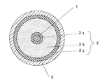
図1によって説明する。1は無酸素銅等からなる内部導体で、通常0.5〜15mm程度の導体径のものが使用される。2は絶縁体層で、内部導体1上に設けられる通常厚さが0.5〜20mm程度の充実体からなる内層2a、発泡体からなる中間層2bおよび充実体からなる外層2cの3層から構成される。内層2aはポリオレフィン系樹脂によって、厚さが0.05〜2mm程度の層として内部導体1上に形成される。また外層2cは、中間層2bを発泡させたときに、ガスを抑え込んで外に逃がさない層として機能する。このように、発泡ガスを適切な溶融破断張力の外層2cによって抑え込むことによって、絶縁体層2の発泡度を高めた発泡体となる。そして前記各層のポリオレフィン系樹脂材料としては、各種グレードの低密度ポリエチレン、中密度ポリエチレン、高密度ポリエチレンやポリプロピレンが単独で或いは混合物として使用される。また混合物とすることによって、中間層2bを適切な溶融破断張力のものに調整することができると共に、外層2cの溶融破断張力を本発明の範囲に調整することが容易となるので好ましい。なお3は外部導体で、通常銅などの薄板等によって構成される。
This will be described with reference to FIG.
そして、外層2cのポリオレフィン系樹脂の溶融破断張力を6〜20gの充実体とするのは、前述のように絶縁体層2の発泡度を高く維持するために特定される。すなわち、溶融破断張力が6g未満のものでは、中間層2bを発泡させる際に高発泡度を得るための溶融時の強度が不十分なため好ましくなく、また溶融破断張力が20gを超えた場合には、被覆が硬くなりすぎ発泡時に膨らみ難くなって、高発泡度とならないため好ましくない。なお、より好ましくは溶融破断張力が10〜20gである。このような溶融破断張力を有するポリオレフィン系樹脂の具体例としては、宇部興産社の高密度ポリエチレンである2070、日本ユニカー社の6944NT、三井化学社のHizex539TE等が、また中密度ポリエチレンである宇部興産社のZM007等や三井化学社のポリプロピレンであるB101WAT、宇部興産社の低密度ポリエチレンであるB028やZ463、日本ユニカー社の1253NT等が単独で或いは混合物として使用される。
And it is specified in order to maintain the foaming degree of the
なお外層2cの厚さは、請求項1に記載されるように、0.3mm以下とする。これは、絶縁体層2の発泡度を78%以上にするために必要な厚さであると共に、これ以上厚くなると、発泡度が上がらず誘電特性(誘電率や誘電正接)が悪くなるので0.3mm以下とするのがよい。より好ましくは、0.05〜0.2mm程度とするのがよい。このような外層2cを有する高周波同軸ケーブルは、発泡時に中間層2bからのガス放出を十分に抑え込むことができ、高発泡度の絶縁体層を確実に形成することができるようになる。さらに前記被覆厚さとすることによって、誘電特性を悪化させることがなく、また絶縁体層2の外径変動の少ない外観が良好な絶縁体層とすることができると共に、高周波帯域(1GHz以上)での減衰量が少ない高周波同軸ケーブルとすることができる。
Note the thickness of the outer layer 2c, as described in
また、絶縁体層2をより好ましい発泡絶縁層とするために、不活性ガスによって形成することによって発泡度が78%以上の高発泡度の絶縁体層2とすることができ、特に高周波帯域(1GHz以上)での減衰量が少ない優れた高周波同軸ケーブルとすることができる。すなわち、窒素ガス、アルゴンガス、フロンガス、炭酸ガス等の不活性ガスによって発泡させることにより、化学発泡剤によって発泡させた場合のように、化学発泡剤の発泡残渣が誘電特性に悪影響を与えたり、発泡度が十分でない等の問題がなくなる。また前記発泡処理に際しては、発泡核剤を添加することが好ましい。このような発泡核剤としては、タルク、ボロンナイトライド、シリカ、ポリテトラフルオロエチレンなどのフッ素系樹脂やビニリデンフロライド−ヘキサフルオロプロピレン共重合体、ポリテトラフルオロエチレン−プロピレン共重合体などのフッ素系ゴムの微粉末が、ポリオレフィン系樹脂100重量部に対して、0.05〜3重量部程度添加される。
Moreover, in order to make the insulator layer 2 a more preferable foamed insulating layer, the
このようにして得られた、請求項2に記載される、発泡度が78%以上の絶縁体層2を有する高周波同軸ケーブルは、減衰量が小さく高周波帯域での誘電特性に優れた高周波同軸ケーブルとなる。すなわち絶縁体層2の発泡度を78%以上とすることによって、@2.2GHz、20Dにおける減衰量を65dB/km以下とすることが可能となり、高周波帯域(1GHz以上)で十分に実用的な高周波同軸ケーブルとなる。
There was thus obtained, according to
そして前述した高周波同軸ケーブルは、請求項3に記載されるように、請求項1または2に記載される高周波同軸ケーブルの外部導体3を、銅製のコルゲート構造とすることによって、高周波同軸ケーブルに十分な可とう性を付与させることができる。この可とう性(或いは屈曲性)としては、Φ200mmまで曲げることが可能となる。このような波型の凹凸のコルゲート加工は、通常行われる方法によって形成すればよい。例えば銅薄板を用いてスパイラル状に波型が形成されたもので、比較的外径が大きな同軸ケーブルであっても十分な可とう性を与えることができる。そして、その外部には保護層として、通常プラスチック材料からなるシースが施される。
As described in
表1に記載する実施例並びに比較例によって、本発明の効果を確認した。表に示した3層構造の高周波同軸ケーブルを作製して、発泡度、中間層2bの発泡状態並びに減衰量を測定した。二段押出機を用い、外径9mmの銅内部導体上に、180〜220℃に調整された第1押出機からポリエチレン樹脂(宇部興産社のC460)を押出し被覆して充実体の内層2aを形成した後、表1に示す組成の種々のポリオレフィン系樹脂からなる発泡させる中間層2bを形成し、さらにその上にポリエチレン樹脂(宇部興産社のZ463)の充実体からなる外層2cを形成させた後に、発泡処理を行った。なお中間層2bの発泡には、窒素ガスを用いた。また中間層2bの発泡核剤としては、富士タルク工業社のPKP−80をポリオレフィン系樹脂100重量部に対して、0.3重量部添加した。このようにして、ケーブル外径(絶縁体層2)が22mmの高周波同軸ケーブルを作製し、試料とした。また比較例として、化学架橋剤によって架橋したポリエチレン樹脂を外層2cとして被覆した高周波同軸ケーブルを用意した。 The effects of the present invention were confirmed by the examples and comparative examples described in Table 1. A high-frequency coaxial cable having a three-layer structure shown in the table was produced, and the degree of foaming, the foaming state of the intermediate layer 2b, and the amount of attenuation were measured. Using a two-stage extruder, a solid inner layer 2a is formed by extruding and coating a polyethylene resin (C460 of Ube Industries) from a first extruder adjusted to 180 to 220 ° C. on a copper inner conductor having an outer diameter of 9 mm. After forming, an intermediate layer 2b to be foamed made of various polyolefin resins having the composition shown in Table 1 was formed, and an outer layer 2c made of a solid body of polyethylene resin (Ube Industries Z463) was further formed thereon. Later, foaming treatment was performed. Nitrogen gas was used for foaming the intermediate layer 2b. Further, as a foam nucleating agent for the intermediate layer 2b, 0.3 part by weight of PKP-80 manufactured by Fuji Talc Kogyo Co., Ltd. was added to 100 parts by weight of the polyolefin resin. Thus, a high frequency coaxial cable having a cable outer diameter (insulator layer 2) of 22 mm was produced and used as a sample. As a comparative example, a high frequency coaxial cable was prepared in which a polyethylene resin crosslinked with a chemical crosslinking agent was coated as the outer layer 2c.
以上の試料を用い、絶縁体層の発泡度(%)を、[(ポリオレフィン系樹脂の比重−発泡後の比重)/(ポリオレフィン系樹脂の比重)]×100として計算した。発泡度が78%以上のものを合格とした。また高周波同軸ケーブルの外部導体を除去して、外層に破れが生じているか否かの状態を観察した。外層に破れがないものを○印で、破れが見られる場合を×印で示した。外層に破れが見られるものは、中間層に連続気泡が多数生じていることがわかっている。さらにネットワークアナライザーを用い、2.2GHzにおける絶縁体層2の減推量(dB/km)を測定した。減推量が65dB/km以下のものを、合格とした。表1に結果を記載した。
Using the above samples, the degree of foaming (%) of the insulator layer was calculated as [(specific gravity of polyolefin resin−specific gravity after foaming) / (specific gravity of polyolefin resin)] × 100. A foam having a foaming degree of 78% or more was regarded as acceptable. In addition, the outer conductor of the high-frequency coaxial cable was removed, and the state of whether or not the outer layer was torn was observed. A case where the outer layer is not torn is indicated by a circle, and a case where a break is observed is indicated by a mark. When the outer layer is broken, it is known that many open cells are generated in the intermediate layer. Further, a reduction amount (dB / km) of the

表1から明らかなとおり、実施例1〜7に記載される本発明の高周波同軸ケーブルは、発泡度が78%以上の高発泡度の絶縁体層を有し、減衰量も65dB/km以下のものであることがわかる。すなわち、外層を形成するポリオレフィン系樹脂として、190℃において内径2.095mm、長さ8.03mmのフラットキャピラリーを用い、ピストンスピード10mm/minで、引取加速度が400m/min2、炉体径が9.55mmのキャピラリーレオメータで測定した溶融破断張力が6〜20gのポリオレフィン系樹脂を用い、また、その被覆厚さを0.3mm以下とすることによって、外層に破れを生じることがないと共に、発泡度が78%以上の高発泡体とすることができる。このような高周波同軸ケーブルは、絶縁体層の外径変動が少なくかつ外観も良好なものであり、また減衰量も65dB/km以下と十分に実用的なものとなる。 As is clear from Table 1, the high-frequency coaxial cables of the present invention described in Examples 1 to 7 have a highly foamed insulator layer with a foaming degree of 78% or more and an attenuation of 65 dB / km or less. It turns out that it is a thing. That is, as the polyolefin resin forming the outer layer, a flat capillary having an inner diameter of 2.095 mm and a length of 8.03 mm at 190 ° C. was used, the piston speed was 10 mm / min, the take-up acceleration was 400 m / min 2 , and the furnace body diameter was 9 By using a polyolefin resin having a melt fracture tension of 6 to 20 g measured with a capillary rheometer of .55 mm and having a coating thickness of 0.3 mm or less, the outer layer is not torn and the foaming degree Can be made into a highly foamed material having a content of 78% or more. Such a high-frequency coaxial cable has a sufficiently small outer diameter variation of the insulator layer and a good appearance, and is sufficiently practical with an attenuation of 65 dB / km or less.
これに対して、比較例1〜4に示す本発明の範囲外の高周波同軸ケーブルは、発泡度、減衰量或いは外層の状態のいずれかに問題があった。すなわち、比較例1のように外層のポリオレフィンの溶融破断張力が1gのように小さい場合には、発泡度が74%であると共に、減衰量も68dB/kmと大きくなっている。また比較例4のように、外層のポリオレフィンの溶融破断張力が30gと大きいと、発泡度が上がらず発泡度も68%であり、減衰量も74dB/kmと大きなものとなる。さらに比較例2や3のように外層のポリエチレンの溶融破断張力が本発明範囲のものであっても、その厚さが0.5mmのように厚くなると、発泡度がそれぞれ72%、69%と低く、また減衰量も70dB/km以上と大きくなって好ましくない。 On the other hand, the high-frequency coaxial cable outside the scope of the present invention shown in Comparative Examples 1 to 4 has a problem in either the degree of foaming, the amount of attenuation, or the state of the outer layer. That is, when the melt fracture tension of the outer layer polyolefin is as small as 1 g as in Comparative Example 1, the degree of foaming is 74% and the attenuation is as large as 68 dB / km. Further, as in Comparative Example 4, when the melt breaking tension of the outer layer polyolefin is as large as 30 g, the foaming degree is not increased, the foaming degree is 68%, and the attenuation is as large as 74 dB / km. Furthermore, even if the melt breaking tension of the outer layer polyethylene is in the range of the present invention as in Comparative Examples 2 and 3, when the thickness is increased to 0.5 mm, the foaming degree is 72% and 69%, respectively. It is not preferable because it is low and the attenuation is as large as 70 dB / km or more.
以上のような高周波同軸ケーブルは、78%以上の高発泡度の絶縁体層を有し、高周波帯域(1GHz以上)で減衰量が少ないと共に可とう性にも優れているので、種々の用途の高周波同軸ケーブルとして使用することができる。 The high-frequency coaxial cable as described above has an insulating layer with a high foaming degree of 78% or more, has a low attenuation in a high-frequency band (1 GHz or more), and is excellent in flexibility. It can be used as a high frequency coaxial cable.
1 内部導体
2 絶縁体層
2a 内層
2b 中間層
2c 外層
3 外部導体
1
Claims (3)
Priority Applications (1)
| Application Number | Priority Date | Filing Date | Title |
|---|---|---|---|
| JP2004302955A JP4518552B2 (en) | 2004-03-12 | 2004-10-18 | High frequency coaxial cable |
Applications Claiming Priority (2)
| Application Number | Priority Date | Filing Date | Title |
|---|---|---|---|
| JP2004071181 | 2004-03-12 | ||
| JP2004302955A JP4518552B2 (en) | 2004-03-12 | 2004-10-18 | High frequency coaxial cable |
Publications (2)
| Publication Number | Publication Date |
|---|---|
| JP2005294244A JP2005294244A (en) | 2005-10-20 |
| JP4518552B2 true JP4518552B2 (en) | 2010-08-04 |
Family
ID=35326908
Family Applications (1)
| Application Number | Title | Priority Date | Filing Date |
|---|---|---|---|
| JP2004302955A Expired - Fee Related JP4518552B2 (en) | 2004-03-12 | 2004-10-18 | High frequency coaxial cable |
Country Status (1)
| Country | Link |
|---|---|
| JP (1) | JP4518552B2 (en) |
Families Citing this family (4)
| Publication number | Priority date | Publication date | Assignee | Title |
|---|---|---|---|---|
| US7390963B2 (en) * | 2006-06-08 | 2008-06-24 | 3M Innovative Properties Company | Metal/ceramic composite conductor and cable including same |
| JP5092555B2 (en) | 2006-06-20 | 2012-12-05 | 日立電線株式会社 | High frequency coaxial cable |
| KR20080074382A (en) * | 2007-02-08 | 2008-08-13 | 엘에스전선 주식회사 | Insulator for coaxial cable, manufacturing method and low loss large diameter coaxial cable using the same |
| JP5459626B2 (en) * | 2011-06-30 | 2014-04-02 | 日本電気株式会社 | Transmission line manufacturing method |
Family Cites Families (5)
| Publication number | Priority date | Publication date | Assignee | Title |
|---|---|---|---|---|
| JP2508128B2 (en) * | 1987-09-09 | 1996-06-19 | 日立電線株式会社 | Method for manufacturing foamed plastic insulated wire |
| JPH0755990B2 (en) * | 1989-11-02 | 1995-06-14 | 宇部興産株式会社 | Expandable polyolefin resin composition for coating electric wires |
| JP2580841B2 (en) * | 1990-05-23 | 1997-02-12 | 日立電線株式会社 | coaxial cable |
| JP3022712B2 (en) * | 1993-10-19 | 2000-03-21 | 三菱電線工業株式会社 | coaxial cable |
| JPH1153969A (en) * | 1997-08-07 | 1999-02-26 | Fujikura Ltd | Manufacturing method of resin insulated cable |
-
2004
- 2004-10-18 JP JP2004302955A patent/JP4518552B2/en not_active Expired - Fee Related
Also Published As
| Publication number | Publication date |
|---|---|
| JP2005294244A (en) | 2005-10-20 |
Similar Documents
| Publication | Publication Date | Title |
|---|---|---|
| JP4435306B2 (en) | Coaxial high frequency cable and its derivatives | |
| CA2524885C (en) | Cable with foamed plastic insulation comprising an ultra-high die swell ratio polymeric material | |
| CN101356591B (en) | High-frequency coaxial cable | |
| JP2014055249A (en) | Foam resin molding, foam insulation electric wire and cable, and production method of foam resin molding | |
| JP4518552B2 (en) | High frequency coaxial cable | |
| JP2006022276A (en) | Insulator composition, high foam insulator using the same, and coaxial cable for high frequency. | |
| JP5303639B2 (en) | Manufacturing method of foamed wire | |
| JP2005343916A (en) | Foam nucleating agent and high-frequency coaxial cable using the same | |
| JP5298148B2 (en) | Foamed coaxial cable | |
| JP2005302412A (en) | High frequency coaxial cable | |
| JP5298146B2 (en) | Thin foam coaxial cable | |
| JP2008021585A (en) | Foamed coaxial cable | |
| JP5426948B2 (en) | Foamed electric wire and transmission cable having the same | |
| JP5420662B2 (en) | Foamed electric wire and transmission cable having the same | |
| JP5420663B2 (en) | Foamed electric wire and transmission cable having the same | |
| JP2006286619A (en) | Thin foam coaxial cable | |
| JP4304183B2 (en) | Foamed coaxial cable | |
| JP5298147B2 (en) | Foamed coaxial cable | |
| JP3962421B1 (en) | Foam molding method, foamed coaxial cable, and foamed coaxial cable manufacturing method | |
| JP2006252820A (en) | Foamed coaxial cable | |
| JP2006253114A (en) | Foamed coaxial cable | |
| JP2004307642A (en) | Olefin resin foam | |
| JP2004238436A (en) | Olefinic resin foam | |
| JP2007048622A (en) | Thin foam coaxial cable | |
| JP2007035417A (en) | coaxial cable |
Legal Events
| Date | Code | Title | Description |
|---|---|---|---|
| A621 | Written request for application examination |
Free format text: JAPANESE INTERMEDIATE CODE: A621 Effective date: 20070615 |
|
| A977 | Report on retrieval |
Free format text: JAPANESE INTERMEDIATE CODE: A971007 Effective date: 20090401 |
|
| A131 | Notification of reasons for refusal |
Free format text: JAPANESE INTERMEDIATE CODE: A131 Effective date: 20090623 |
|
| A521 | Request for written amendment filed |
Free format text: JAPANESE INTERMEDIATE CODE: A523 Effective date: 20090824 |
|
| A521 | Request for written amendment filed |
Free format text: JAPANESE INTERMEDIATE CODE: A821 Effective date: 20090824 |
|
| TRDD | Decision of grant or rejection written | ||
| A01 | Written decision to grant a patent or to grant a registration (utility model) |
Free format text: JAPANESE INTERMEDIATE CODE: A01 Effective date: 20100419 |
|
| A01 | Written decision to grant a patent or to grant a registration (utility model) |
Free format text: JAPANESE INTERMEDIATE CODE: A01 |
|
| A61 | First payment of annual fees (during grant procedure) |
Free format text: JAPANESE INTERMEDIATE CODE: A61 Effective date: 20100517 |
|
| FPAY | Renewal fee payment (event date is renewal date of database) |
Free format text: PAYMENT UNTIL: 20130528 Year of fee payment: 3 |
|
| R151 | Written notification of patent or utility model registration |
Ref document number: 4518552 Country of ref document: JP Free format text: JAPANESE INTERMEDIATE CODE: R151 |
|
| FPAY | Renewal fee payment (event date is renewal date of database) |
Free format text: PAYMENT UNTIL: 20140528 Year of fee payment: 4 |
|
| R250 | Receipt of annual fees |
Free format text: JAPANESE INTERMEDIATE CODE: R250 |
|
| R250 | Receipt of annual fees |
Free format text: JAPANESE INTERMEDIATE CODE: R250 |
|
| R250 | Receipt of annual fees |
Free format text: JAPANESE INTERMEDIATE CODE: R250 |
|
| R250 | Receipt of annual fees |
Free format text: JAPANESE INTERMEDIATE CODE: R250 |
|
| R250 | Receipt of annual fees |
Free format text: JAPANESE INTERMEDIATE CODE: R250 |
|
| R250 | Receipt of annual fees |
Free format text: JAPANESE INTERMEDIATE CODE: R250 |
|
| R250 | Receipt of annual fees |
Free format text: JAPANESE INTERMEDIATE CODE: R250 |
|
| R250 | Receipt of annual fees |
Free format text: JAPANESE INTERMEDIATE CODE: R250 |
|
| LAPS | Cancellation because of no payment of annual fees |