JP4518098B2 - Color mixing determination method and image recording method and apparatus - Google Patents
Color mixing determination method and image recording method and apparatus Download PDFInfo
- Publication number
- JP4518098B2 JP4518098B2 JP2007107628A JP2007107628A JP4518098B2 JP 4518098 B2 JP4518098 B2 JP 4518098B2 JP 2007107628 A JP2007107628 A JP 2007107628A JP 2007107628 A JP2007107628 A JP 2007107628A JP 4518098 B2 JP4518098 B2 JP 4518098B2
- Authority
- JP
- Japan
- Prior art keywords
- color
- recording medium
- ink
- recording
- Prior art date
- Legal status (The legal status is an assumption and is not a legal conclusion. Google has not performed a legal analysis and makes no representation as to the accuracy of the status listed.)
- Expired - Fee Related
Links
Images


Description
本発明は、混色判定方法並びに画像記録方法及び装置に係り、特に、多数のノズルから記録媒体に向けてインクを吐出して画像を記録する際の記録媒体表面上でのインクの混色を回避する技術に関する。 The present invention relates to a color mixing determination method and an image recording method and apparatus, and in particular, avoids color mixing of ink on the surface of a recording medium when an image is recorded by ejecting ink from a large number of nozzles toward the recording medium. Regarding technology.
従来より、画像記録装置として、多数のノズルを配列させたインクジェットヘッド(インク吐出ヘッド)を有し、このインクジェットヘッドと記録媒体を相対的に移動させながら、ノズルからインクを吐出することにより、記録媒体上に画像を記録するインクジェット記録装置(インクジェットプリンタ)が知られている。 2. Description of the Related Art Conventionally, an image recording apparatus has an inkjet head (ink ejection head) in which a large number of nozzles are arranged, and recording is performed by ejecting ink from the nozzles while relatively moving the inkjet head and the recording medium. 2. Related Art An ink jet recording apparatus (ink jet printer) that records an image on a medium is known.
このようなインクジェット記録装置におけるインクの吐出方法として、従来から様々な方法が知られている。例えば、圧電素子(圧電セラミック)の変形によって圧力室(インク室)の一部を構成する振動板を変形させて、圧力室の容積を変化させ、圧力室の容積増大時にインク供給路から圧力室内にインクを導入し、圧力室の容積減少時に圧力室内のインクをノズルから液滴として吐出する圧電方式や、インクを加熱して気泡を発生させ、この気泡が成長する際の膨張エネルギーでインクを吐出させるサーマルインクジェット方式などが知られている。 Conventionally, various methods are known as ink ejection methods in such an ink jet recording apparatus. For example, the diaphragm constituting a part of the pressure chamber (ink chamber) is deformed by deformation of the piezoelectric element (piezoelectric ceramic) to change the volume of the pressure chamber, and when the volume of the pressure chamber is increased, Ink is introduced into the pressure chamber, and when the volume of the pressure chamber is reduced, the ink is ejected as droplets from the nozzle, or the ink is heated to generate bubbles and the expansion energy when the bubbles grow. A thermal ink jet method for discharging is known.
インクジェット記録装置のようなインク吐出ヘッドを有する画像記録装置においては、インクを貯蔵するインクタンクからインク供給路を介してインク吐出ヘッドにインクを供給し、上記様々な吐出方法でインクを吐出しているが、複数の異なる色のインクを用いてカラー画像を記録する場合に、先に記録したインクがまだ定着・硬化しないうちに、それと異なる色のインクを重ねて記録すると、混色が発生して画質が低下する。 In an image recording apparatus having an ink discharge head such as an ink jet recording apparatus, ink is supplied from an ink tank for storing ink to an ink discharge head via an ink supply path, and ink is discharged by the above various discharge methods. However, when recording a color image using a plurality of different color inks, if the previously recorded ink is not yet fixed and cured, recording with the different color inks may cause color mixing. The image quality is degraded.
そこで従来より、異なる色のインクを重ねて記録した場合に発生する混色を防止し、画質を向上させるための様々な方法が提案されている。 In view of this, various methods have been proposed in the past for preventing color mixing that occurs when inks of different colors are overlaid and improving image quality.
例えば、記録媒体を保持する回転体の1回転中に、各色用記録ヘッドから吹き付けられる各色インクドットが、記録媒体上の回転方向と同じ副走査方向に、少なくとも1ドット分だけ離れた状態で間引き記録されるようにして、隣接するインクドットの混ざりや流れを防止しつつ、高画質記録を行うようにしたものが知られている(例えば、特許文献1等参照)。 For example, during one rotation of the rotating body holding the recording medium, each color ink dot sprayed from the recording head for each color is thinned out at least one dot away in the same sub-scanning direction as the rotation direction on the recording medium. It is known that recording is performed so that high-quality recording is performed while preventing mixing and flow of adjacent ink dots (see, for example, Patent Document 1).
また例えば、インクジェット記録装置において、記録したインクの乾燥状態を推定する手段を有し、その推定結果に応じて、記録媒体の搬送速度を変えたり、記録ヘッドの間隔を変えることにより、前の記録と次の記録との記録間隔を変えるようにして、記録装置のスループットを維持しながら、異なるインクが重畳する部分の記録乱れを防止し、画像品位を向上させるようにしたものが知られている(例えば、特許文献2等参照)。 Further, for example, the inkjet recording apparatus has a means for estimating the dry state of the recorded ink, and the previous recording can be performed by changing the conveyance speed of the recording medium or changing the interval between the recording heads according to the estimation result. In order to improve the image quality, the recording interval between one recording and the next recording is changed to prevent the recording disturbance in the portion where different inks are superimposed while maintaining the throughput of the recording apparatus. (For example, see Patent Document 2).
また例えば、カラーインクジェット記録方法において、同一印字領域に対しては、複数のヘッドのうち少なくとも1つのヘッドによる印字を、他のヘッドによる印字時点よりも、隣接ヘッドの印字遅れ時間よりも十分長い時間をおいた後、印字するようにして色間にじみのないカラープリントを得るようにしたものが知られている(例えば、特許文献3等参照)。
しかしながら、例えば、上記特許文献1に記載のものでは、記録媒体を保持した回転体が1回転する際に、1ドット間引いて記録しており、1画像全体を記録するのに複数回転しなければならず、生産性が低いという問題がある。
However, for example, in the one described in
また、上記特許文献2に記載のものでは、乾燥を推定する手段と、ドット記録間隔を調整する手段を有し、乾燥状態に応じて次のドットを記録する間隔を調整するようにしているが、記録媒体に着弾したインクを定着させたり硬化させる手段は有しておらず、単に自然乾燥に任せているのみであり、必ずしも混色を確実に防ぐことはできないという問題があった。
Moreover, although the thing of the said
さらに、上記特許文献3に記載のものも、単に隣接ドット印字遅れ以上の時間を取るのみで、定着、硬化を調整する手段は有しておらず、上記特許文献2と同様の問題がある。
Further, the one described in Patent Document 3 has a problem similar to that of
本発明は、このような事情に鑑みてなされたもので、記録媒体上にインク吐出装置から吐出され記録媒体表面上に着弾したインクの混色を判定し、混色を回避した画像記録を可能とする混色判定方法並びに画像記録方法及び装置を提供することを目的とする。 The present invention has been made in view of such circumstances, and it is possible to determine the color mixture of ink ejected from an ink ejection device onto a recording medium and landed on the surface of the recording medium, thereby enabling image recording while avoiding the color mixture. It is an object of the present invention to provide a color mixing determination method and an image recording method and apparatus.
前記目的を達成するために、請求項1に記載の発明は、第1色のインクを吐出するノズル列を有する第1の印字ヘッドから記録媒体に向けて打滴を行うとともに、該第1の印字ヘッドと前記記録媒体とを相対移動させることにより、同記録媒体上に第1色のインクドットによるドット列が前記相対移動方向に複数列並んで一体となった矩形状の第1色領域を印字する工程と、前記第1色と異なる第2色のインクを吐出するノズル列を有する第2の印字ヘッドから前記記録媒体上の前記第1色領域と一部が重なり合って隣接する範囲に打滴を行うとともに、該第2の印字ヘッドと前記記録媒体とを相対移動させることにより、前記第2色のインクドットによるドット列が前記相対移動方向に複数列並び、かつ当該第2色のインクドットによるドット列の一部が前記第1色領域と重なり合って一体となった矩形状の第2色領域を印字する工程と、によって、前記第1色領域と前記第2色領域とが部分的に重なり合った混色判定用パッチを形成し、前記第1色領域と前記第2色領域とが隣り合う方向に沿って、前記混色判定用パッチにおける前記第1色領域と前記第2色領域の重なり部分を含む複数箇所について、前記第1色及び第2色の各色の濃度を濃度計により測定し、当該濃度測定により前記隣り合う方向についての各色の濃度プロフィールを得る工程を、当該混色判定用パッチに関して前記隣り合う方向と直交する方向の複数の位置で行い、前記複数の位置に対応した複数組の2色分の濃度プロフィールを得て、各組の2色分の濃度プロフィールからそれぞれ所定の閾値となる濃度点間の距離を求め、当該距離の平均値及び標準偏差の少なくとも一方を算出し、前記算出された平均値及び標準偏差のうち少なくとも一方に基づいて前記重なり部分における2色の混色状態を判定することを特徴とする混色判定方法を提供する。 In order to achieve the above object, according to the first aspect of the present invention, droplets are ejected from a first print head having a nozzle array for ejecting ink of the first color toward a recording medium, and the first By moving the print head and the recording medium relative to each other, a rectangular first color area in which a plurality of dot rows of ink dots of the first color are aligned in the relative movement direction on the recording medium is integrated. A printing process and a second print head having a nozzle row that ejects ink of a second color different from the first color are applied to a range where the first color area on the recording medium partially overlaps and is adjacent. By performing droplets and relatively moving the second print head and the recording medium, a plurality of dot rows of ink dots of the second color are arranged in the relative movement direction, and the ink of the second color Do by dot A step of printing a rectangular second color area in which a part of the first color area overlaps with the first color area, and the first color area and the second color area partially overlap each other. And forming an overlapping portion of the first color region and the second color region in the color mixture determination patch along a direction in which the first color region and the second color region are adjacent to each other. The step of measuring the density of each color of the first color and the second color with a densitometer and obtaining a density profile of each color in the adjacent direction by the density measurement with respect to the patch for color mixture determination It is performed at a plurality of positions in a direction orthogonal to the adjacent direction, and a plurality of sets of two color density profiles corresponding to the plurality of positions are obtained, and a predetermined threshold value is obtained from each set of two color density profiles. Dark It obtains distances between points, and calculate at least one of the mean and standard deviation of the distance, determining the color mixture state of two colors in the overlapping portion based on at least one of the mean and standard deviation the calculated There is provided a color mixing determination method characterized by the above.
これにより、記録媒体上に吐出されたインクの混色を容易に自動的に判定することができる。 Thereby, the color mixture of the ink ejected on the recording medium can be easily determined automatically.
また、請求項2に記載の発明は、請求項1記載の混色判定方法において、前記重なり部分における前記第1色のインクドットを吐出し始めるタイミングと前記第2色のインクドットを吐出し始めるタイミングとの吐出時間差、前記第1及び第2の印字ヘッドに対する前記記録媒体の相対搬送速度、前記記録媒体上のインクドットを前記記録媒体に定着させる定着エネルギー、及び、前記記録媒体上のインクを硬化させる硬化エネルギーのうち少なくとも一つをパラメータとして複数段階変化させて複数の混色判定用パッチを同一の記録媒体上に形成し、当該複数の混色判定用パッチを有する混色判定プリント上の各混色判定用パッチについて、それぞれ前記濃度プロフィールに基づく前記重なり部分の混色状態の判定を行うことを特徴とする混色判定方法を提供する。
Further, the invention according to
なお、2色のドットの吐出時間差は、記録媒体の搬送速度を変更するかまたは各色毎に設けられたヘッド間距離を変更することで変えることができる。 Note that the ejection time difference between the two color dots can be changed by changing the conveyance speed of the recording medium or changing the distance between the heads provided for each color.
また、同様に前記目的を達成するために、請求項3に記載の発明は、請求項2記載の混色判定方法において、前記距離の平均値、標準偏差、前記吐出時間差、前記記録媒体上に記録するものがテキストか画像かあるいはその両方かを示す記録モード、のそれぞれに応じて混色の判定に用いる評価値を算出するための要素に対して重み付けして前記評価値を算出して前記混色状態の判定を行うことを特徴とする混色判定方法を提供する。 Similarly, in order to achieve the above object, according to a third aspect of the present invention, in the color mixing determination method according to the second aspect, the average value of the distance, the standard deviation, the discharge time difference, and the recording on the recording medium. ones recording mode indicating whether text or images or both, of the color mixing state by calculating the evaluation value by weighting factors for calculating the evaluation value used in the determination of the color mixing according to the respective The present invention provides a color mixing determination method characterized by performing the determination .
これにより、記録データの種類による記録モードに応じて混色を判定する際の重み付けを変更することで高い画質を保持することが可能となる。 Accordingly, it is possible to maintain high image quality by changing the weighting when determining the color mixture according to the recording mode depending on the type of recording data.
また、同様に前記目的を達成するために、請求項4に記載の発明は、請求項2又は3記載の混色判定方法による混色判定結果に基づいて、前記吐出時間差、前記相対搬送速度、前記定着エネルギー、及び、前記硬化エネルギーのうち少なくとも一つを制御するための制御パラメータを設定し、その設定に基づき前記記録媒体上に画像記録を行うことを特徴とする画像記録方法を提供する。
Further, in order to attain the aforementioned object, the invention according to claim 4, based on the color mixing evaluation result by
また、請求項5に記載の発明は、請求項4記載の画像記録方法であって、さらに、前記インクの種類、前記記録媒体の種類、及び、前記記録媒体上に記録するものがテキストか画像かあるいはその両方かを示す記録モード、に応じて前記制御パラメータを設定するようにしたことを特徴とする画像記録方法を提供する。 The invention according to claim 5 is the image recording method according to claim 4 , wherein the type of ink , the type of the recording medium, and what is recorded on the recording medium is text or image According to another aspect of the present invention, there is provided an image recording method in which the control parameter is set in accordance with a recording mode indicating either or both.
これにより、混色判定結果を利用して混色を回避した高画質の画像記録が可能となる。 Thus, high-quality image recording that avoids color mixture using the color mixture determination result is possible.
また、同様に前記目的を達成するために、請求項6に記載の発明は、第1色のインクを吐出するノズル列を有する第1の印字ヘッドから記録媒体に向けて打滴を行うとともに、該第1の印字ヘッドと前記記録媒体とを相対移動させることにより、同記録媒体上に第1色のインクドットによるドット列が前記相対移動方向に複数列並んで一体となった矩形状の第1色領域を印字する制御を行う一方、前記第1色と異なる第2色のインクを吐出するノズル列を有する第2の印字ヘッドから前記記録媒体上の前記第1色領域と一部が重なり合って隣接する範囲に打滴を行うとともに、該第2の印字ヘッドと前記記録媒体とを相対移動させることにより、前記第2色のインクドットによるドット列が前記相対移動方向に複数列並び、かつ当該第2色のインクドットによるドット列の一部が前記第1色領域と重なり合って一体となった矩形状の第2色領域を印字する制御を行うことによって、前記第1色領域と前記第2色領域とが部分的に重なり合った混色判定用パッチを形成する混色判定プリント出力手段と、前記第1色領域と前記第2色領域とが隣り合う方向に沿って、前記混色判定用パッチにおける前記第1色領域と前記第2色領域の重なり部分を含む複数箇所について、前記第1色及び第2色の各色の濃度を測定し、当該濃度測定により前記隣り合う方向についての各色の濃度プロフィールを得る濃度測定手段と、当該混色判定用パッチに関して前記隣り合う方向と直交する方向の複数の位置で前記濃度測定を行い、前記複数の位置に対応した複数組の2色分の濃度プロフィールを得て、各組の2色分の濃度プロフィールからそれぞれ所定の閾値となる濃度点間の距離を求め、当該距離の平均値及び標準偏差の少なくとも一方を算出し、前記算出された平均値及び標準偏差のうち少なくとも一方に基づいて前記重なり部分における2色の混色状態を判定する混色判定手段と、を備えることを特徴とする混色判定装置を提供する。 Similarly, in order to achieve the above object, the invention according to claim 6 performs droplet ejection from the first print head having a nozzle row for ejecting the first color ink toward the recording medium, By moving the first print head and the recording medium relative to each other, a rectangular first shape in which a plurality of dot rows of ink dots of the first color are arranged side by side in the relative movement direction on the recording medium. While performing control to print one color area, the first color area on the recording medium partially overlaps from a second print head having a nozzle row that ejects ink of a second color different from the first color. In addition, when droplets are ejected in adjacent ranges and the second print head and the recording medium are relatively moved, a plurality of dot rows of ink dots of the second color are arranged in the relative movement direction, and The second color The first color area and the second color area are partly obtained by performing control to print a rectangular second color area in which a part of a dot row of ink dots overlaps and is integrated with the first color area. and color mixing evaluation print output means for forming a manner overlapping color mixing evaluation patches, and wherein the first color regions along the second color regions and the direction in which the adjacent, said in the color mixing evaluation patches first color regions Density measuring means for measuring a density of each of the first color and the second color at a plurality of locations including an overlapping portion of the second color region, and obtaining a density profile of each color in the adjacent direction by the density measurement; to obtain the perform the concentration measurement at a plurality of positions in the direction orthogonal to the direction in which adjacent the terms mixing evaluation patch, a plurality of sets of density profiles of two colors corresponding to the plurality of locations The distance between the density points, which are the predetermined threshold values, is obtained from the density profiles for the two colors of each set, and at least one of the average value and the standard deviation of the distance is calculated, and the calculated average value and standard deviation are calculated. There is provided a color mixing determining device comprising: a color mixing determining means for determining a color mixing state of two colors in the overlapping portion based on at least one of them .
請求項7に記載の発明は、請求項6記載の混色判定装置において、前記混色判定プリント出力手段は、前記重なり部分における前記第1色のインクドットを吐出し始めるタイミングと前記第2色のインクドットを吐出し始めるタイミングとの吐出時間差、前記第1及び第2の印字ヘッドに対する前記記録媒体の相対搬送速度、前記記録媒体上のインクドットを前記記録媒体に定着させる定着エネルギー、及び、前記記録媒体上のインクを硬化させる硬化エネルギーのうち少なくとも一つをパラメータとして複数段階変化させて複数の混色判定用パッチを同一の記録媒体上に形成し、当該複数の混色判定用パッチを有する混色判定プリントを出力することを特徴とする混色判定装置を提供する。 According to a seventh aspect of the present invention, in the mixed color determination apparatus according to the sixth aspect, the mixed color determination print output means starts the ejection of the first color ink dots in the overlapping portion and the second color ink. Discharge time difference from the timing to start ejecting dots , relative conveyance speed of the recording medium with respect to the first and second print heads, fixing energy for fixing ink dots on the recording medium to the recording medium, and the recording A color mixture determination print having a plurality of color mixture determination patches formed on the same recording medium by changing at least one of the curing energies for curing ink on the medium as a parameter, and having the plurality of color mixture determination patches. Is provided. The present invention provides a color mixing judgment device characterized in that
また、請求項8に記載の発明は、請求項7記載の混色判定装置において、前記混色判定手段は、前記距離の平均値、標準偏差、前記吐出時間差、前記記録媒体上に記録するものがテキストか画像かあるいはその両方かを示す記録モード、のそれぞれに応じて混色の判定に用いる評価値を算出するための要素に対して重み付けして前記評価値を算出して前記混色状態の判定を行うことを特徴とする混色判定装置を提供する。 According to an eighth aspect of the present invention, in the color mixing determination device according to the seventh aspect, the color mixing determination means records the average value of the distance, the standard deviation, the discharge time difference, and the text recorded on the recording medium. The color mixing state is determined by calculating the evaluation value by weighting the element for calculating the evaluation value used for the determination of the color mixture according to each of the recording modes indicating the image, the image, or both. There is provided a color mixing judgment device characterized by the above.
また、同様に前記目的を達成するために、請求項9に記載の発明は、第1色のインクを吐出するノズル列を有する第1の印字ヘッドと、前記第1色と異なる第2色のインクを吐出するノズル列を有する第2の印字ヘッドと、前記第1及び第2の印字ヘッドに対して前記記録媒体を相対的に移動させる手段と、を備え、前記記録媒体上にドットを吐出して画像記録を行う画像記録装置であって、請求項6乃至8の何れか1項に記載の混色判定装置を有するとともに、前記第1及び第2の印字ヘッドによるドットの吐出時間差を制御する吐出時間差制御手段と、前記記録媒体上に打滴されたドットを定着させる定着手段と、前記定着手段の定着エネルギーを制御する定着制御手段と、前記記録媒体上に打滴されたドットを硬化させる硬化手段と、前記硬化手段の硬化エネルギーを制御する硬化制御手段と、前記混色判定装置による混色判定結果に基づいて、前記吐出時間差制御手段、前記定着制御手段及び前記硬化制御手段のうち少なくとも一つを制御する制御パラメータを設定するパラメータ設定手段と、を備え、前記パラメータ設定手段で設定された制御パラメータによって画像記録を行うことを特徴とする画像記録装置を提供する。 Similarly, in order to achieve the object, the invention according to claim 9 includes a first print head having a nozzle array for discharging the first color ink, and a second color different from the first color. A second print head having a nozzle array for ejecting ink, and means for moving the recording medium relative to the first and second print heads, and ejects dots onto the recording medium. An image recording apparatus that performs image recording by using the color mixing determination apparatus according to any one of claims 6 to 8, and controls a difference in dot ejection time between the first and second print heads. curing the discharge time difference controlling means, and fixing means for fixing the ejected dots on said recording medium, and a fixing control means for controlling the fixing energy of the fixing means, the ejected dot on said recording medium Curing means, A curing control means for controlling the curing energy of the serial curing means, on the basis of the color mixing evaluation result by the mixing evaluation device, the discharge time difference control unit, control for controlling at least one of the fixing control unit and the hardening control means comprises a parameter setting means for setting the parameters, and to provide an image recording apparatus which is characterized in that the parameter set control parameter images recorded by the at setting means.
これにより混色回避に最適な制御パラメータを自動的に設定することができる。 As a result, it is possible to automatically set the optimum control parameters for avoiding color mixing.
また、同様に前記目的を達成するために、請求項10に記載の発明は、第1色のインクを吐出するノズル列を有する第1の印字ヘッドと、前記第1色と異なる第2色のインクを吐出するノズル列を有する第2の印字ヘッドと、前記第1及び第2の印字ヘッドに対して前記記録媒体を相対的に移動させる手段と、前記第1の印字ヘッドから記録媒体に向けて打滴を行うとともに、該第1の印字ヘッドと前記記録媒体とを相対移動させることにより、同記録媒体上に第1色のインクドットによるドット列が前記相対移動方向に複数列並んで一体となった矩形状の第1色領域を印字する制御を行う一方、前記第2の印字ヘッドから前記記録媒体上の前記第1色領域と一部が重なり合って隣接する範囲に打滴を行うとともに、該第2の印字ヘッドと前記記録媒体とを相対移動させることにより、前記第2色のインクドットによるドット列が前記相対移動方向に複数列並び、かつ当該第2色のインクドットによるドット列の一部が前記第1色領域と重なり合って一体となった矩形状の第2色領域を印字する制御を行うことによって、前記第1色領域と前記第2色領域とが部分的に重なり合った混色判定用パッチを形成する混色判定プリント出力手段と、記録データを前記記録媒体に記録する際の前記第1の印字ヘッドによるドットを吐出し始めるタイミングと前記第2の印字ヘッドによるドットを吐出し始めるタイミングとの吐出時間差を制御する吐出時間差制御手段と、前記記録媒体上に打滴されたドットを定着させる定着手段と、前記定着手段の定着エネルギーを制御する定着制御手段と、前記記録媒体上に打滴されたドットを硬化させる硬化手段と、前記硬化手段の硬化エネルギーを制御する硬化制御手段と、前記混色判定用パッチに基づき、2色のドットの混色の判定結果が入力される混色判定結果入力手段と、前記混色判定結果入力手段に入力された混色の判定結果に基づいて、前記吐出時間差制御手段、前記定着制御手段及び前記硬化制御手段のうち少なくとも一つを制御する制御パラメータを設定するパラメータ設定手段と、を備え、前記パラメータ設定手段の設定された制御パラメータによって画像記録を行うことを特徴とする画像記録装置を提供する。
Similarly, in order to achieve the above object, the invention according to
これにより、例えば目視等によって判定された混色判定結果を入力することにより、制御パラメータが設定される。 Thereby, for example, the control parameter is set by inputting the color mixture determination result determined by visual observation or the like.
さらに、請求項11に記載の発明は、請求項9または10に記載の画像記録装置であって、さらに、インクの種類を検出するインク種検出手段と、前記記録媒体の種類を検出する記録媒体種検出手段と、記録データから記録するものがテキストか画像かあるいはその両方かを示す記録モードを検出する記録モード検出手段を備え、前記インク種、前記記録媒体種及び記録モードに応じて前記制御パラメータを設定記憶する手段を有することを特徴とする画像記録装置を提供する。
Furthermore, the invention according to claim 11 is the image recording apparatus according to
これらの装置により、前記混色判定方法及び画像記録方法が実行され、混色を回避した高画質な画像を得ることができる。 With these devices, the color mixture determination method and the image recording method are executed, and a high-quality image that avoids color mixture can be obtained.
以上説明したように、本発明に係る混色判定方法並びに画像記録方法及び装置によれば、記録媒体上に吐出され記録媒体表面上に着弾したインクの混色を判定し、混色を回避した高画質の画像記録が可能となる。 As described above, according to the color mixing determination method and the image recording method and apparatus according to the present invention, it is possible to determine the color mixing of the ink ejected onto the recording medium and landed on the surface of the recording medium, thereby preventing the color mixture. Image recording is possible.
以下、添付した図面を参照して、本発明に係る混色判定方法並びに画像記録方法及び装置について詳細に説明する。 Hereinafter, a color mixing determination method, an image recording method, and an apparatus according to the present invention will be described in detail with reference to the accompanying drawings.
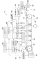
図1は、本発明の第1実施形態に係る画像記録装置としてのインクジェット記録装置の概略を示す一部ブロック図を含む概略構成図である。 FIG. 1 is a schematic configuration diagram including a partial block diagram showing an outline of an ink jet recording apparatus as an image recording apparatus according to the first embodiment of the present invention.
図1に示すように、インクジェット記録装置10は、主に、インクの色(イエロー(Y)、シアン(C)、マゼンタ(M)、黒(K))毎に設けられた複数の印字ヘッド12Y、12C、12M、12Kと、給紙部14から記録媒体である記録紙16を印字ヘッド12Y等へ搬送する搬送部18と、記録紙16上に吐出されたインクを定着させる定着・硬化手段20(定着手段)等を有して構成される。
As shown in FIG. 1, the ink
記録紙16は、図1に示したものでは、給紙部14のマガジン22に装填されたロール紙(連続用紙)をカッター24で所定長に切断して用いるようにしているが、紙幅や紙質等が異なる複数のマガジンを併設してもよい。また、ロール紙のマガジンに代えて、又はこれと併用して、カット紙が積層装填されたカセットによって用紙を供給してもよい。
In the
ロール紙を使用する装置構成の場合、図1のように、裁断用のカッター24が設けられており、該カッター24によってロール紙は所望のサイズにカットされる。なお、カット紙を使用する場合には、カッター24は不要である。
In the case of an apparatus configuration using roll paper, a
また、本実施形態においては、紙の種類情報を記録したバーコードあるいは無線タグ等の情報記録体がマガジン22の媒体種検出ノッチ22aに取り付けられており、その情報記録体の情報を読み取るための媒体種検出手段25が設置されている。後述するように、媒体種検出手段25によって読み取られた情報を用いて、その記録媒体に対する画像記録に最適な制御パラメータが設定されて画像記録が行われる。なお、本明細書で画像記録というときには、画像データのみに限らずテキストデータ等の記録も含むものとする。
In the present embodiment, an information recording body such as a bar code or a wireless tag recording paper type information is attached to the medium
マガジン22から送り出される記録紙16は、マガジン22に装填されていたことによる巻き癖が残り、カールする。図示は省略したが、このカールを除去するために、デカール処理部を設けてマガジンの巻き癖方向と逆方向に加熱ドラム等で記録紙16に熱を与え、多少印字面が外側に弱いカールとなるように加熱温度を制御するとより好ましい。
The
搬送部18は、ローラ26、27間に無端状のベルト29が巻き掛けられた構造を有し、少なくとも印字ヘッド12K等のノズル面に対向する部分が平面(フラット面)をなすように構成されている。
The
ベルト29は、記録紙16の幅よりも広い幅寸法を有しており、ベルト面には多数の吸
引孔(図示省略)が形成されている。図1に示したように、2つのローラ26、27の間に掛け渡されたベルト29の内側において、印字ヘッド12Y、12C、12M、12Kのノズル面に対向する位置には吸着チャンバ30が設けられており、この吸着チャンバ30をファン32で吸引して負圧にすることによって、ベルト29上の記録紙16が吸着保持される。
The
ベルト29が巻かれているローラ26、27の少なくとも一方(例えば図1に示すように、左のローラ26)にモータ34の動力が伝達されることにより、ベルト29は、図1において反時計回りに駆動され、ベルト29上に保持された記録紙16は図1の右から左へと相対的搬送速度Vで搬送されるようになっている。
When the power of the
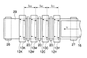
図2に、印字ヘッド12Y、12C、12M、12K付近を拡大した平面図を示す。図2に示すように、印字ヘッド12Y、12C、12M、12Kは、各色(YCMK)に対応し、それぞれが複数のノズルを配列したノズル列13Y、13C、13M、13K等を有し、記録紙16の全幅を担うように、各印字ヘッド12Y、12C、12M、12Kの長手方向を記録紙16の搬送方向(図に矢印Vで示す方向)と直交する紙幅方向に並べた構成で、最大紙幅に対応する長さを有するフルライン型ヘッドとなっている。また、各印字ヘッド12Y、12C、12M、12Kの間にはやはり記録紙16の全幅に対応する長さを有する定着・硬化手段20がそれぞれ配置されている。
FIG. 2 shows an enlarged plan view of the vicinity of the print heads 12Y, 12C, 12M, and 12K. As shown in FIG. 2, the print heads 12Y, 12C, 12M, and 12K correspond to the respective colors (YCMK), and each have a
なお、ここでフルライン型ヘッドには、短尺の記録ヘッドを用紙幅に複数並べた形式のものも含むものとする。 Here, the full-line type head includes a type in which a plurality of short recording heads are arranged in the paper width.
各印字ヘッド12Y、12C、12M、12Kには、それぞれノズル列13Y、13C、13M、13Kが複数配列されノズルが2次元マトリクス状に配列されている。また、各印字ヘッド12Y、12C、12M、12Kのそれぞれ記録紙16の搬送方向上流側のノズル列間の距離を各印字ヘッド12Y、12C、12M、12Kのノズル間距離Sと言う。具体的には、図2に示すように印字ヘッド12Yの搬送方向上流側のノズル列13Yと印字ヘッド12Cの搬送方向上流側のノズル列13Cとの間の距離をこれら2色Y、C間のノズル列間距離SCYといい、以下同様に印字ヘッド12Cのノズル列13Cと印字ヘッド12Mのノズル列13Mとの間のノズル列間距離SMC、及び印字ヘッド12Mのノズル列13Mと印字ヘッド12Kのノズル列13Kとの間のノズル列間距離SKMを同様に定義する。これらのノズル列間距離SCY、SMC、SKMは可変であり自由に制御することができるようになっている。
In each of the print heads 12Y, 12C, 12M, and 12K, a plurality of
図1あるいは図2に示すように、記録紙16の搬送方向(図の右から左方向)に沿って上流側からY(イエロー)、C(シアン)、M(マゼンタ)、K(黒)の順に各色インクに対応した印字ヘッド12Y、12C、12M、12Kが配置されている。記録紙16を搬送部18によって搬送しつつ各印字ヘッド12Y、12C、12M、12Kからそれぞれ色インクを吐出することにより記録紙16上にカラー画像を形成することができる。
As shown in FIG. 1 or FIG. 2, Y (yellow), C (cyan), M (magenta), and K (black) from the upstream side along the conveyance direction of the recording paper 16 (right to left in the figure). Print heads 12Y, 12C, 12M, and 12K corresponding to the respective color inks are arranged in order. A color image can be formed on the
このように記録紙16を搬送しながら画像記録を行うため、記録紙16の搬送速度によって記録データ(印字データ)を記録紙16に記録する際の記録速度に対応する異なる2色のドットの吐出時間差が略決まる。したがって、記録紙16の搬送速度を高くしてそれに合わせて印字ヘッド12Y、12C、12M、12Kからインクを吐出して記録すればこの吐出時間差を短く(記録速度を速く)することができる。
In order to perform image recording while transporting the
本実施形態では、このドットの吐出時間差は、このような記録媒体の搬送速度を制御することによって、あるいは2色のドットを形成するヘッド間の距離を変えることによって変えることができる。 In this embodiment, the dot ejection time difference can be changed by controlling the conveyance speed of such a recording medium or by changing the distance between the heads that form two-color dots.
上述したように、紙幅の全域をカバーするフルラインヘッドがインク色毎に設けられてなる印字ヘッド12Y、12C、12M、12Kによれば、紙搬送方向について、記録紙16と印字ヘッド12Y、12C、12M、12Kを相対的に移動させる動作を一回行うだけで(すなわち、一回の走査で)記録紙16の全面に画像を高速で記録することができる。
As described above, according to the print heads 12Y, 12C, 12M, and 12K in which full line heads that cover the entire paper width are provided for each ink color, the
また、各印字ヘッド12Y、12C、12M、12Kに各色のインクを供給するインクタンク(図示せず)近傍には、インクの種類を検出するインク種検出手段28(図1参照)が設けられている。インク種検出手段28は、特に限定されるものではなく、例えば、カートリッジ式のインクタンクの場合、カートリッジに取り付けられた情報媒体等からインク種を示すIDを読み取るような構成でもよい。
Further, an ink type detection means 28 (see FIG. 1) for detecting the type of ink is provided in the vicinity of an ink tank (not shown) that supplies each color ink to each
なお、本例では、YCMKの標準色(4色)の構成を例示したが、インク色や色数の組み合わせについては本実施形態には限定されず、必要に応じて淡インク、濃インクを追加してもよい。例えば、ライトシアン、ライトマゼンタ等のライト系インクを吐出する印字ヘッドを追加する構成も可能である。 In this example, the configuration of the standard colors of YCMK (four colors) is illustrated, but the combination of ink colors and the number of colors is not limited to this embodiment, and light ink and dark ink are added as necessary. May be. For example, it is possible to add a print head that discharges light ink such as light cyan and light magenta.
再び図1に戻り、各印字ヘッド12Y、12C、12M、12Kは、ヘッドドライバ36によってインク吐出が制御される。また、各印字ヘッド12Y、12C、12M、12K間に設けられる定着・硬化手段20は、印字ヘッド12Y、12C、12M、12Kから記録紙16上に吐出されたインクを定着させるものであり、使用されるインクに応じて好適な手段が用いられる。
Returning to FIG. 1 again, the ink ejection of the print heads 12Y, 12C, 12M, and 12K is controlled by the
ここで定着というのは、記録紙16上に着弾したインクの紙の繊維内への浸透と、表面からのインクの乾燥の両方を合わせた内容を指すものとし、記録紙16表面に着弾したインク液滴が存在しなくなることを言う。例えば、水系のインクの場合には、定着・硬化手段20としては、例えばヒータ等の熱エネルギーを付与する装置、あるいは赤外線照射装置、または風(熱風)を吹き付けるファン(熱風ファン)などが例示され、これらのインクを定着させる装置は単独で用いても良いし、複数を組み合わせて用いてもよい。
Here, the term “fixing” refers to the content of both the penetration of the ink landed on the
定着・硬化手段20は、図1あるいは図2に示すように4つの印字ヘッド12Y、12C、12M、12Kのそれぞれの間に設置され、各印字ヘッドから吐出されたインクを定着させ、引き続いて次の印字ヘッドからその上あるいは近傍にインクが吐出されても各インクが混色しないようにするものである。
As shown in FIG. 1 or FIG. 2, the fixing / curing means 20 is installed between the four
本実施形態においては、各色用の印字ヘッド12Y、12C、12M、12Kの各ノズル列間距離(印字ヘッド12Yと12Cのノズル列13Yと13C間の距離SCY、印字ヘッド12Cと12Mのノズル列13Cと13M間の距離SMC、印字ヘッド12Mと12Kのノズル列13Mと13K間の距離SKM)の制御、記録紙16の相対的搬送速度(吐出時間差)の制御、定着・硬化手段20におけるインクの定着エネルギーを制御することによる定着時間の制御という3種類の制御量の制御のうち、少なくともいずれか1つ以上の制御を行うことによって、インクの混色を防止しつつ高速で記録を行うようにするものである。
In this embodiment, the distance between the nozzle rows of the print heads 12Y, 12C, 12M, and 12K for each color (the distance S CY between the
なお、本実施形態では、実際にノズル列間距離を可変にする場合には、印字ヘッド毎の距離を可変にすることで各ノズル列間距離を可変にしているため、ノズル列間距離の制御を印字ヘッド間距離の制御と言っても同じである。 In the present embodiment, when the distance between the nozzle rows is actually made variable, the distance between the nozzle rows is made variable by changing the distance for each print head. Is the same as controlling the distance between the print heads.
さらに本実施形態では、ノズル列間距離(印字ヘッド間距離)、相対的搬送速度(吐出
時間差)及び定着時間(定着エネルギー)を制御して混色を回避する際、特に最も速く記録できるような各制御量の最適値をパラメータとして設定することにより、混色を防止するとともに、同時に高速で記録することが可能となる。
Further, in the present embodiment, when the color mixing is avoided by controlling the distance between the nozzle rows (distance between the print heads), the relative conveyance speed (difference in discharge time), and the fixing time (fixing energy), each recording that can be recorded most quickly. By setting the optimum value of the control amount as a parameter, it is possible to prevent color mixing and simultaneously record at high speed.
このため、本実施形態のインクジェット記録装置10は、上に述べたものの他に、混色回避制御に係る手段として、まず混色を判定する混色判定部(混色判定装置)35をはじめとして、ノズル列間距離(印字ヘッド間距離)を制御するヘッド間距離制御手段38、記録紙16の相対的搬送速度Vを制御することにより吐出時間差を制御する相対的搬送速度制御手段40(以下、単に搬送制御手段40と言う)、定着・硬化手段20の定着エネルギーを制御してインクの定着時間を制御する定着制御手段42、相対的搬送速度が可変にされた場合に記録画像のドットピッチを揃えるための周波数制御手段44、各制御手段が最適な制御をなすように制御パラメータを設定するためのパラメータ設定手段46を有している。また、搬送制御手段40が相対的搬送速度Vを制御するために、相対的搬送速度Vを検出するためのエンコーダ41が、ローラ26に設置されている。
For this reason, the
混色判定部35は、詳しくは後述するが混色を判定するための混色判定パターン(混色判定用パッチ)が形成された混色判定プリントを出力するための混色判定プリント出力手段48、出力された混色判定プリントの混色判定用パッチの濃度測定を行う濃度計45及び濃度計45の測定結果を用いて混色判定を行う混色判定手段49等から構成されている。この混色判定方法については詳しくは後述する。
Although described in detail later, the color
ヘッド間距離制御手段38は、各色の印字ヘッド12Y、12C、12M、12Kを紙搬送方向に移動して隣接した印字ヘッド間の距離(一つの印字ヘッド上に形成されたノズル列と隣接した印字ヘッド上に形成されたノズル列とのノズル間距離SCY、SMC、SKM等)を変えることにより、各印字ヘッド12Y、12C、12M、12K(のノズル列)から記録紙16へのインク吐出タイミングを制御するものである。
The head-to-head distance control means 38 moves the print heads 12Y, 12C, 12M, and 12K of the respective colors in the paper transport direction to determine the distance between adjacent print heads (print adjacent to the nozzle row formed on one print head. By changing the inter-nozzle distances S CY , S MC , S KM, etc. with the nozzle row formed on the head, ink from each
例えば、より混色防止効果を高めようとする場合には、このノズル列間距離を大きくして、一つのノズル列から吐出されたインクが次の印字ヘッドのノズル列からインクが吐出されるまでの間に、より乾燥(定着)するようにする。各ノズル列間距離を変更する具体的手段としては、特に限定されるものではなく、例えば、ボールねじ等によりフルライン型ヘッドの両端に設けたレール上を各印字ヘッド12Y、12C、12M、12Kが移動可能としたものでもよい。 For example, in order to increase the effect of preventing color mixing, the distance between the nozzle rows is increased so that the ink ejected from one nozzle row is ejected from the nozzle row of the next print head. In between, try to dry (fix) more. The specific means for changing the distance between the nozzle rows is not particularly limited. For example, the print heads 12Y, 12C, 12M, and 12K are arranged on rails provided at both ends of the full-line head by a ball screw or the like. May be movable.
搬送制御手段40は、ロータリエンコーダ41の検出信号に基づいて、モータ34の回転数を制御するものである。このとき、後述するようにパラメータで最適な相対的搬送速度Vが設定されている場合には、記録紙16の相対的搬送速度がその速度となるようにモータ34の回転を制御する。
The
定着制御手段42は、例えば、定着・硬化手段20が熱を付与する装置であればその設定温度を変更することにより付与する熱エネルギーを制御したり、また例えば熱風を送るファンの回転数を変更したりして、記録紙16上のインクの定着エネルギーを制御することによって定着時間t1を制御するものである。
For example, if the fixing /
周波数制御手段44は、記録紙16の相対的搬送速度Vが変更された場合に、それに合わせて各印字ヘッド12Y、12C、12M、12Kからのインク吐出タイミングを制御して記録画像が所定のドットピッチの画像となるようにして画像の品質を一定に保持するものである。
When the relative conveyance speed V of the
パラメータ設定手段46は、混色判定プリントの濃度測定結果により判定された混色判
定結果に基づいてヘッド間距離制御手段38、搬送制御手段(吐出時間差制御手段)40及び定着制御手段42の少なくとも一つを制御するために各制御手段に最適なパラメータを設定するためのものである。
The
なお、以上説明した実施形態に係るインクジェット記録装置10においては、定着制御手段42により定着・硬化手段20を制御して記録紙16上に吐出されたインクを定着させて混色を防ぐようにしているが、例えば、UV光の照射を受けることによって重合反応を起こし硬化するUV硬化インクあるいは一般に電磁輻射線硬化インクを用いて、これに電磁輻射線を照射する照射装置等の硬化手段21を前記定着・硬化手段20の代わりに設置して、これを硬化制御手段43により制御することによりインクを硬化させてインクの混色を防止するようにしてもよい。
In the
ここで、硬化とは、電磁輻射線等の光照射あるいは熱の付与等による化学変化によってインクの成分が固くなってインクが記録紙16の表面上に固定されることを言う。硬化手段21としては、例えばUV硬化インクの場合には、UV光照射装置、ハロゲンランプ、LEDレーザ等の照射装置等が例示される。また、この他ソリッドインクの場合には、ペルチェ等あるいは水冷等の冷却装置を用いてもよい。
Here, “curing” means that the ink component is hardened and fixed on the surface of the
以下、定着制御手段42及び定着・硬化手段20を用いた場合について説明するが、図1に示すように、これの代わりに硬化制御手段43及び硬化手段21を用いてもよく、その場合にも制御は全く同様である。すなわち、硬化制御手段43は、例えば硬化手段21の照射光量や照射領域を変更して記録紙16上のインクの硬化エネルギーを制御することにより硬化時間t2を制御するようにしてもよい(記録媒体表面のインク液滴を硬化させることで表面インク液滴の存在をなくし、混色を防止できる。)。
Hereinafter, the case where the fixing
図3は、インクジェット記録装置10のシステム構成を示す要部ブロック図である。インクジェット記録装置10は、通信インターフェース50、システムコントローラ52、画像メモリ54、モータドライバ56、ヒータドライバ58、プリント制御部60、画像バッファメモリ62、ヘッドドライバ36等を備えている。
FIG. 3 is a principal block diagram showing the system configuration of the
通信インターフェース50は、ホストコンピュータ64から送られてくる画像データ(記録データ)を受信するインターフェース部である。通信インターフェース50にはUSB、IEEE1394、イーサネット(登録商標)、無線ネットワークなどのシリアルインターフェースやセントロニクスなどのパラレルインターフェースを適用することができる。この部分には、通信を高速化するためのバッファメモリ(図示省略)を搭載してもよい。ホストコンピュータ64から送出された画像データは通信インターフェース50を介してインクジェット記録装置10に取り込まれ、一旦画像メモリ54に記憶される。画像メモリ54は、半導体素子からなるメモリに限らず、ハードディスクなど磁気媒体を用いてもよい。
The
システムコントローラ52は、通信インターフェース50、画像メモリ54、モータドライバ56、ヒータドライバ58等の各部を制御する制御部である。システムコントローラ52は、中央演算処理装置(CPU)及びその周辺回路等から構成され、ホストコンピュータ64との間の通信制御、画像メモリ54の読み書き制御等を行うとともに、搬送系のモータ34やヒータ66を制御する制御信号を生成する。
The
モータドライバ56は、システムコントローラ52からの指示にしたがってモータ34を駆動するドライバ(駆動回路)である。ヒータドライバ58は、システムコントローラ52からの指示にしたがって印字後の記録紙16を乾燥させる後乾燥部(図示省略)等のヒータ66を駆動するドライバである。
The
プリント制御部60は、システムコントローラ52の制御に従い、画像メモリ54内の画像データから印字制御用の信号を生成するための各種加工、補正などの処理を行う信号処理機能を有し、生成した印字制御信号(印字データ)をヘッドドライバ36に供給する制御部である。プリント制御部60において所要の信号処理が施され、該画像データに基いてヘッドドライバ36を介して印字ヘッド12Y、12C、12M、12Kのインク液滴の吐出量や吐出タイミングの制御が行われる。これにより、所望のドットサイズやドット配置が実現される。
The
プリント制御部60には画像バッファメモリ62が備えられており、プリント制御部60における画像データ処理時に画像データやパラメータなどのデータが画像バッファメモリ62に一時的に格納される。なお、図3において、画像バッファメモリ62はプリント制御部60に付随する態様で示されているが、画像メモリ54と兼用することも可能である。また、プリント制御部60とシステムコントローラ52とを統合して一つのプロセッサで構成する態様も可能である。
The
ヘッドドライバ36はプリント制御部60から与えられる印字データに基いて各色の印字ヘッド12K、12C、12M、12Yのアクチュエータを駆動する。ヘッドドライバ36にはヘッドの駆動条件を一定に保つためのフィードバック制御系を含んでもよい。
The
また、本実施形態におけるインクジェット記録装置10は、この他に、隣り合った印字ヘッド(本例では図1あるいは図2に示すように、印字ヘッド12Yと12C、印字ヘッド12Cと12M、印字ヘッド12Mと12Kが該当する。)のヘッド間距離SCY、SMC、SKMを制御するヘッド間距離制御手段38、記録紙16の相対的搬送速度Vを制御する搬送制御手段40、定着・硬化手段20の定着エネルギーを制御して記録紙16に吐出されたインクの定着時間t1を制御する定着制御手段42、相対的搬送速度Vが変更された場合にそれに応じてインク吐出周波数を制御する周波数制御手段44、各制御手段を制御するためのパラメータを設定するパラメータ設定手段46及び詳しくは後述する混色判定プリントを出力するための混色判定用パターンを形成してヘッドドライバ36を通じて印字ヘッド12Y、12C、12M、12Kから混色判定プリントを出力する混色判定プリント出力手段48及び混色判定プリントの濃度測定結果により混色判定を行う混色判定手段49等を有している。
In addition, the ink
ここで、周波数制御手段44及び混色判定プリント出力手段48は、プリント制御部60内に設けられ、システムコントローラ52によって制御されるようになっている。また、詳しくは後述するが、混色判定手段49の中には濃度測定の結果得られた濃度プロフィールを用いて混色判定に用いる所定の数値を算出するための平均値/標準偏差算出手段51が設けられている。さらに、システムコントローラ52には、画像データ(記録データ)からその記録モードを検出する記録モード検出手段53が設けられている。ここで、記録モードとは、その記録データがテキストのみから構成されているか、画像データのみから構成されてか、あるいはテキスト及び画像データの両方を含んでいるかということを示すものである。
Here, the
次に、混色を判定して混色防止かつ高速記録のための最適なパラメータを各制御手段に対して設定する方法について説明する。そのために、まず混色を判定するための混色判定用パターンの作成について説明する。 Next, a method for determining color mixing and setting optimum parameters for preventing color mixing and high-speed recording for each control means will be described. For this purpose, the creation of a color mixture determination pattern for determining color mixture will be described first.
この混色判定用パターンは、図1あるいは図2に示すようにインクジェット記録装置10における隣り合った2つの印字ヘッド(12Yと12C、12Cと12M、12Mと12K)から吐出される2色のインク(Y(イエロー)とC(シアン)、CとM(マゼンタ)、MとK(黒))がどのように混ざり合うかを調べるために、搬送速度V(吐出時間差
あるいは記録速度に対応する)及び定着エネルギーEを複数段階変化させて記録することによって作成される。
As shown in FIG. 1 or FIG. 2, the mixed color determination pattern is obtained by using two colors of ink (12Y and 12C, 12C and 12M, 12M and 12K) ejected from two adjacent print heads (12Y and 12C). In order to examine how Y (yellow) and C (cyan), C and M (magenta), and M and K (black)) are mixed, a conveyance speed V (corresponding to a discharge time difference or a recording speed) and It is created by recording the fixing energy E in a plurality of stages.
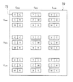
図4に混色判定パターンの例を示す。図4に示すように、混色判定パターン70は、相対搬送速度V及び定着エネルギーEをそれぞれ高(max)、中(mid)、低(low)の3段階に変化させて記録したものであり、各隣り合った2色のインクの組み合わせ毎に9通りの混色判定パターンから成るパッチ72(混色判定用パッチ)から形成されている。ここで、搬送速度V及び定着(硬化)エネルギーEの3段階のmaxは最高速度(あるいは最高エネルギー)、midは最高値の2/3程度の中位の値、lowは最高値の1/3程度の低位の値を示している。
FIG. 4 shows an example of the color mixture determination pattern. As shown in FIG. 4, the color
なお、本実施例は搬送速度Vを変化させて(ヘッド間距離は一定)、異なる2色のドットの吐出時間差を変えたものであるが、ヘッド間距離を変化させて(搬送速度Vは一定)吐出時間差を変えてパッチを形成しても良い。 In this embodiment, the conveyance speed V is changed (the distance between the heads is constant), and the difference in ejection time between the two different color dots is changed, but the distance between the heads is changed (the conveyance speed V is constant). ) Patches may be formed by changing the discharge time difference.
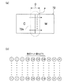
混色判定パターン70のパッチ72は、図5(a)に示すように2色(例えば、CとM)を左右に並べて、それを矩形状に印字(記録)したものである。特に、2色の境界部分72aは、図5(b)に拡大して示すように、混色を調べるために数百ドットを重ね打ちしている。
As shown in FIG. 5A, the
この2色のインクが混色する様子を図6に示す。図6(a)に示すように、記録紙16上にYインク74を吐出し、少しずらしてCインク76を一部が重なるように吐出する。Yインク74は、記録紙16中に符号74aで示すように浸透して行くとともに、記録紙16表面上では乾燥が進行する。
FIG. 6 shows how these two colors of ink are mixed. As shown in FIG. 6A, the
このとき、Yインク74がまだ定着しない間にCインク76を吐出すると、重なった部分75において混色(滲み)が発生する。そして、図6(b)に示すように、重なった部分75で両色が混ざった(滲みが発生した)ままの状態で定着する。
At this time, if the
混色判定プリント出力手段48は、図4及び図5に示したような混色判定パターン70のデータを生成し、あるいは所定のメモリから呼び出してヘッドドライバ36を通じて混色判定パターン70のデータを印字ヘッド12Y、12C、12M、12Kへ送り、混色判定プリントとして出力するものである。
The color mixture determination print output means 48 generates data of the color
出力された混色判定プリントの各パッチ72(混色判定用パッチ)は濃度計45によって濃度測定される。この濃度測定の原理を図7に示す。
The density of each patch 72 (color mixing determination patch) of the output color mixing determination print is measured by the
図7に示すように、RGB発光素子90から射出された微小スポット光91を媒体92上の測定ポイントに当てて、その反射光をCCD素子等の受光素子93で受光することによって微小部分における濃度測定を行うことができる。このときRGB発光素子としては、例えばハロゲンランプにフィルタを組み合わせたもの等が考えられる。
As shown in FIG. 7, the
または、例えば図7(b)に示すようにRGB発光素子94から射出されたエリア光95を媒体92の測定ポイントに当てて、その反射光をレンズ96でエリアCCD97上に集光して測定するようにしてもよい。
Alternatively, for example, as shown in FIG. 7B, the area light 95 emitted from the RGB
この測定は、図5(a)に示すように2色の境界部分72aを、図の縦方向にN等分(例えば10等分以上)に分割して、矢印Fで示すように左右にスキャンすることによって行われる。さらに詳しく言うと、この濃度測定は、図5(a)に矢印Dで示す、ドット重ね打ち部分(図5(b)参照)の3倍程度の領域を、左右に毎秒50〜100μm程度の
微小走査することによって行われる。
In this measurement, as shown in FIG. 5A, the
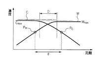
濃度計45による測定結果は混色判定手段49に送られるようになっている。混色判定パターン70を出力した混色判定プリントの各パッチ72(混色判定用パッチ)の濃度測定結果の1例を図8にグラフで示す。図5(a)の各矢印Fに沿った走査に対してこのような濃度プロフィールを示すグラフが1つずつ得られることになる。実線で示したのがそれぞれCインク及びMインクの混色(滲み)が発生したときの濃度であり、一点鎖線で示したのが混色のない理想状態における濃度である。
The result of measurement by the
混色判定手段49の平均値/標準偏差算出手段51は、Mの最高濃度Mmax に対して所定の閾値、例えば60%の濃度点PM と、Cの最高濃度Cmax に対して所定の閾値、例えば60%の濃度点PC との距離dを算出し、1つのパッチ72に対して、縦方向にN等分(10等分以上)した複数箇所で行われた各走査に対して得られる各距離dの標準偏差σd及び平均値av( d)を計算する。この距離dの標準偏差σdあるいは平均値av( d)が小さい程混色が少ないことになる。
The average value / standard deviation calculating means 51 of the color
そして、混色判定手段49は、図9に示すように、この計算した標準偏差σd及び平均値av( d)の少なくとも一方が最小となるような搬送速度Vと定着エネルギーEの組み合わせを、パラメータ設定手段46に送る。 Then, as shown in FIG. 9, the color mixture determining means 49 sets a parameter for a combination of the conveyance speed V and the fixing energy E that minimizes at least one of the calculated standard deviation σd and average value av (d). Send to means 46.
パラメータ設定手段46は、この標準偏差σd及び平均値av( d)の少なくとも一方が最小となるような搬送速度Vと定着エネルギーEの組み合わせを、記録紙16におけるこの2色のインクに対する混色を回避するための最適なパラメータとして設定する。またパラメータ設定手段46は、このパラメータを媒体種検出手段25及びインク種検出手段28から送られた記録紙16の種類及びインクの種類と対応付けて記憶しておく。
The parameter setting means 46 avoids color mixing of the two colors of ink on the
ここで、標準偏差σdが最小となるような搬送速度Vと定着エネルギーEの組み合わせを選ぶのは、視覚上の混色とのリンクを考慮したためであり、平均値av( d)が最小となるものを選ぶのは、混色による解像度低下がこの平均値av( d)に反映されると考えられるからである。このようにして混色を最も少なくすることができる。 Here, the combination of the conveyance speed V and the fixing energy E that minimizes the standard deviation σd is selected in consideration of the link with visual color mixture, and the average value av (d) is minimized. This is because it is considered that the resolution reduction due to the color mixture is reflected in the average value av (d). In this way, color mixing can be minimized.
このように、混色の最も少ないエネルギーE(定着エネルギーあるいは硬化エネルギー)と搬送速度Vを設定することにより、印字ヘッド間距離Sが一定であるとすれば、定着エネルギーEによる定着時間t1あるいは硬化エネルギーEによる硬化時間t2に対し、S/V>t1あるいはS/V>t2を満たすようにすることができる。 Thus, if the distance S between the print heads is constant by setting the energy E (fixing energy or curing energy) with the least color mixture and the conveying speed V, the fixing time t1 or the curing energy based on the fixing energy E is set. S / V> t1 or S / V> t2 can be satisfied with respect to the curing time t2 by E.
以下、本実施形態の作用を図10のフローチャートに沿って説明する。 Hereinafter, the operation of the present embodiment will be described along the flowchart of FIG.
まず、図15のステップS100において、インクジェット記録装置10に記録紙16を供給するためのマガジン22を装填する。前述したように、マガジン22には、装填されている記録紙16の種類等の情報が記録された情報記録体が媒体種検出ノッチ22aに取り付けられており、この情報を媒体種検出手段25で読み取る。媒体種検出手段25によって読み取られた情報は、パラメータ設定手段46に送られる。一方で、インク種検出手段28によりインクの種類が検出され、検出されたインク種の情報は同様にパラメータ設定手段46に送られる。
First, in step S100 of FIG. 15, a magazine 22 for supplying the
次のステップS110において、パラメータ設定手段46は、送られた媒体種情報等に対応する最適パラメータがすでに設定され、記憶されているか否か判断する。その媒体種等に対応する最適なパラメータが存在する場合には、ステップS120へ進み、パラメータ設定手段46内に記憶されている、その最適パラメータ(搬送速度V、定着(硬化)エ
ネルギーE)を呼び出して、それぞれ搬送制御手段40、定着制御手段42及び必要に応じてヘッド間距離制御手段38等に設定する。
In the next step S110, the parameter setting means 46 determines whether the optimum parameter corresponding to the sent medium type information or the like has already been set and stored. If there is an optimum parameter corresponding to the medium type or the like, the process proceeds to step S120, and the optimum parameter (conveying speed V, fixing (curing) energy E) stored in the parameter setting means 46 is called. Thus, they are set in the conveyance control means 40, the fixing control means 42, and the head distance control means 38, if necessary.
一方、検出された媒体種等に対応する最適なパラメータが存在しない場合には、最適なパラメータを設定するための混色判定パターンを作成するためにステップS130に進む。なお、マガジン22に情報記録体が取り付けられていない場合や、取り付けられていても媒体種検出手段25で読み取れなかった場合には、例えば、ダミーの媒体種をパラメータ設定手段46に送り、対応する最適パラメータが存在しないとして、同様にステップS130へ進むようにする。
On the other hand, if there is no optimum parameter corresponding to the detected medium type or the like, the process proceeds to step S130 in order to create a color mixture determination pattern for setting the optimum parameter. If the information recording medium is not attached to the magazine 22 or if it is attached but cannot be read by the medium
ステップS130においては、前述したような方法で、隣り合った各印字ヘッド(12Yと12C、12Cと12M、12Mと12K)に対して、搬送速度V(吐出時間差)及び定着エネルギーEを複数段階変えて各パッチを出力し、図4に示すような混色判定パターンを作成する。 In step S130, the conveyance speed V (discharge time difference) and the fixing energy E are changed in a plurality of steps for each adjacent print head (12Y and 12C, 12C and 12M, 12M and 12K) by the method described above. Each patch is output to create a color mixture determination pattern as shown in FIG.
次に、ステップS140において、濃度計45で混色判定パターンの各パッチの、特に境界部分の濃度を測定し、図8に示すような濃度プロフィールを採集する。測定した濃度プロフィールは、混色判定手段49へ送られる。
Next, in step S140, the
次にステップS150では、混色判定手段49の平均値/標準偏差算出手段51において、前述したように各濃度プロフィールを用いて各色の最高濃度値の60%の濃度点間の距離の平均値av( d)及び標準偏差σdを算出し、これらの少なくとも一方を最小とするような搬送速度V及び定着エネルギーEの組合わせを選び、パラメータ設定手段46において、これを最適パラメータとして設定するとともに記憶しておく。
In step S150, the average value / standard
次にステップS160において、これらの最適パラメータを用いて画像記録(プリント)が行われる。また、ステップS110において、最適パラメータが存在するとしてステップS120でこの最適パラメータを設定した場合も、ステップS160でプリントが行われる。 In step S160, image recording (printing) is performed using these optimum parameters. In addition, if it is determined in step S110 that an optimum parameter exists and this optimum parameter is set in step S120, printing is performed in step S160.
このように本実施形態によれば、予め記録媒体及びインクの種類に応じて、混色を回避するための最適なパラメータを設定しておくことにより、後は記録媒体の種類等を検出するのみで、容易に混色を回避することができる。また、記録媒体の種類を検出できない場合でも、混色判定用パターンを作成して混色判定プリントを出力して、これを濃度測定して濃度プロフィールを得て、これに基づいて混色回避に最適なパラメータを設定することにより、混色を回避して高画質な画像記録を行うことができる。 As described above, according to the present embodiment, the optimum parameters for avoiding color mixing are set in advance according to the type of the recording medium and the ink, and then only the type of the recording medium is detected. Color mixing can be avoided easily. Even if the type of the recording medium cannot be detected, a color mixture determination pattern is created and a color mixture determination print is output, and this is subjected to density measurement to obtain a density profile. By setting, it is possible to avoid color mixing and perform high-quality image recording.
また、本実施形態において、濃度計45で混色判定パターン70を濃度測定した後の処理として次のような方法も考えられる。
In the present embodiment, the following method is also conceivable as processing after the density measurement of the color
すなわち、濃度計45で上と同様にして測定した濃度プロフィールを混色判定手段49へ送り、混色判定手段49において、2色の濃度プロフィールにおいて所定閾値(例えば、最高濃度に対し60%の濃度点等)となる点間の距離dを算出し、複数の測定で得られた複数の濃度プロフィールにおけるこの距離dの標準偏差σd及び平均値av( d)を算出する。
That is, the density profile measured in the same manner as above with the
そして、算出した各距離dの標準偏差σd及び平均値av( d)に対して、図11に示すような対応関係にある目標値(例えば、距離の平均値としては図5(a)あるいは図8に示す重ね打ち長さDの2倍等)、補正係数a1、a2、及び重み係数b1、b2を決定する。この補正係数及び重み係数は以下説明する混色を判定するための評価値を算出するた
めの要素(ファクター)に対して掛けられるものである。
Then, for the calculated standard deviation σd and average value av (d) of each distance d, a target value having a correspondence as shown in FIG. 11 (for example, the average value of the distance is shown in FIG. 8), correction coefficients a1 and a2, and weighting coefficients b1 and b2. The correction coefficient and the weighting coefficient are applied to an element (factor) for calculating an evaluation value for determining the color mixture described below.
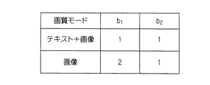
ここで、重み係数b1、b2は、画像データ(記録データ)を基に記録モード検出手段53によって検出された記録モードにより、例えば図12に示すように、文字データと画像の組み合わせを記録するモードと、画像のみを記録するモードに対応して決定される。例えば、テキストと画像を両方記録するモードの場合には、重み係数b1、b2はb1=b2=1と平等とし、画像モードの場合には、b1=2、b2=1と重み係数b1の方を大きく設定する。 Here, the weighting factors b1 and b2 are modes in which a combination of character data and an image is recorded, for example, as shown in FIG. 12, according to the recording mode detected by the recording mode detecting means 53 based on the image data (recording data). And determined in accordance with the mode for recording only the image. For example, in the mode in which both text and image are recorded, the weighting factors b1 and b2 are equal to b1 = b2 = 1, and in the image mode, b1 = 2, b2 = 1 and the weighting factor b1. Set a larger value.
そしてこれらの値を用いて次の式(1)で与えられる混色判定関数によって混色を判定する。 Then, using these values, the color mixture is determined by the color mixture determination function given by the following equation (1).
混色判定関数f = σd×a1×b1 + |av( d)−D|×a2×b2
・・・(1)
すなわち、この混色判定関数fの値を、混色を判定するための評価値とし、この値が小さいほど混色が少ないと判定される。そこで、パラメータ設定手段46は、この混色判定関数fの値が最小となるようなパッチ72に対応する相対的搬送速度V及び定着エネルギーEの組み合わせを混色回避に最適なパラメータとして設定する。
Color mixing determination function f = σd × a1 × b1 + | av (d) −D | × a2 × b2
... (1)
That is, the value of the color mixture determination function f is used as an evaluation value for determining color mixture, and it is determined that the smaller the value, the less color mixture. Therefore, the
また、以上説明したように混色判定パターンを作成し、これを用いて、前述した不等式S/V>t1あるいはS/V>t2を満たし、混色を回避する最適なパラメータを記録媒体種に対応づけて設定する方法の他に、直接に、ヘッド間距離S(SCY、SMC、SKM)、搬送速度V、定着時間t1あるいは硬化時間t2(定着エネルギーあるいは硬化エネルギー)を上記不等式を満たすように制御することによって、混色を回避するようにしてもよい。この場合、各記録媒体種に対する、定着エネルギーと定着時間t1との関係、あるいは硬化エネルギーと硬化時間t2との関係は予め取得しておくものとする。
Further, as described above, a color mixture determination pattern is created, and this is used to associate an optimum parameter that satisfies the inequality S / V> t1 or S / V> t2 and avoids color mixture with a recording medium type. In addition to the above-described method, the head distance S (S CY , S MC , S KM ), the conveyance speed V, the
ヘッド間距離S(印字ヘッド12Yと12C間の距離SCY、印字ヘッド12Cと12M間の距離SMC、印字ヘッド12Mと12K間の距離SKM)は、ヘッド間距離制御手段38によって制御される。例えば、定着時間t1が決まっている場合に、吐出時間差を短くしようとして、搬送速度Vを速くする場合に、ヘッド間距離Sを大きくする必要が生ずる。
The head distance S (distance S CY between the print heads 12Y and 12C, distance S MC between the
また、印字ヘッド12Y等が記録紙16の全幅方向に対応する長尺ラインヘッドで構成されている場合に、搬送方向下流側のヘッド配置を記録紙16の浸透圧減少に合わせて、ヘッド間距離Sを長くするように配置するようにしてもよい。さらに、記録紙16のインク浸透量に合わせて定着制御手段42により定着・硬化手段20を制御して、乾燥を強化するようにしてもよい。
Further, when the
また、本実施形態において、印字ヘッド12Y、12C、12M、12Kの配置は、浸透・乾燥が遅く、定着時間の長いインクを使用しているヘッド、あるいは硬化エネルギー量の大きいインクを使用しているヘッド程、搬送方向上流側に配置するようにすることが好ましい。さらにヘッド間距離Sを変えたり、搬送速度Vを変えて印字を行う場合に、記録画像が所定のドットピッチとなるように、各印字ヘッド12Y、12C、12M、12Kの吐出周波数を制御することが好ましい。吐出周波数の制御は、搬送制御手段40から搬送速度情報を受けて、周波数制御手段44によって行われる。
In this embodiment, the arrangement of the print heads 12Y, 12C, 12M, and 12K uses a head that uses ink with slow penetration and drying and a long fixing time, or ink with a large amount of curing energy. It is preferable that the head is disposed on the upstream side in the transport direction. Further, when printing is performed by changing the distance S between the heads or by changing the conveyance speed V, the ejection frequency of each of the print heads 12Y, 12C, 12M, and 12K is controlled so that the recorded image has a predetermined dot pitch. Is preferred. The discharge frequency is controlled by the
次に、本発明の第2実施形態について説明する。 Next, a second embodiment of the present invention will be described.
図13は、本発明の第2実施形態に係るインクジェット記録装置110の印字ヘッドの付近を拡大して示す平面図を含む混色回避制御に係る制御手段を示すブロック図である。
FIG. 13 is a block diagram illustrating a control unit related to the color mixture avoidance control including a plan view illustrating an enlarged vicinity of the print head of the
図13に示すように、第2実施形態の印字ヘッド112は、記録紙116の幅方向に往復運動しながら画像記録を行うシャトル型ヘッドである。このとき、印字ヘッド112は、記録紙116の幅方向の一方の端から他方の端まで一方向に移動するときにのみ画像記録を行い、他方の端まで移動した後、再びこちら側の一方の端までもどってくるときには画像記録は行わない。
As shown in FIG. 13, the
印字ヘッド112には、YMCKの各色のインクを吐出する各色毎のノズル列112Y、112C、112M、112Kが印字ヘッド112の移動方向(記録紙116の幅方向)に対して略垂直な方向に平行に並んで配置されている。各色毎のノズル列112Y、112C、112M、112Kは、印字ヘッド112の記録時の移動方向の上流側からこの順で各隣接したノズル列間距離S(ノズル列112Yとノズル列112C間のノズル列間距離SCY、ノズル列112Cとノズル列112M間のノズル列間距離SMC、ノズル列112Mとノズル列112K間のノズル列間距離SKM)を変更可能な状態で配列されている。
On the
各ノズル列112Y、112C、112M、112Kのそれぞれの下流側には、定着・硬化手段120がこれらと平行に配置されている。
Fixing / curing means 120 is disposed in parallel to the downstream sides of the
また、記録紙116は、印字ヘッド112が記録を行いながら記録紙116の幅方向の一方の端から他方の端へ向かって移動しているときには静止している。そして、印字ヘッド112が記録紙116の幅方向の一方の端から他方の端まで記録を終了し、再びこちら側の一方の端までもどってくるときには、記録紙116は印字ヘッド112がいま記録した記録紙116の幅方向の帯状の領域の幅(ノズル列112Y等の幅)に相当する分だけ記録紙116幅方向と垂直な方向に搬送されるようになっている。
The
このように、本実施形態においては、印字ヘッド112がシャトル型ヘッドであるため、前述した第1実施形態とは異なり、画像記録時には記録紙116は静止して印字ヘッド112のみが移動する。この印字ヘッド112の移動方向が上記第1実施形態における(記録紙16と印字ヘッド12との)相対的搬送方向に相当する。
Thus, in this embodiment, since the
また、図13に示すように、本実施形態のインクジェット記録装置110も、前述した第1実施形態と同様に、混色回避制御に係る手段として、ノズル列間距離制御手段138(第1実施形態のヘッド間距離制御手段38に対応)、ノズルドライバ136(第1実施形態のヘッドドライバ36に対応)、搬送制御手段140、定着制御手段142、周波数制御手段144、パラメータ設定手段146、混色判定プリント出力手段148及び濃度計145と混色判定手段149等を有している。なお、ノズルドライバ136は、各ノズル列におけるインク吐出を制御するもので、第1実施形態のヘッドドライバ36に対応する。
Further, as shown in FIG. 13, the
ノズル列間距離制御手段138は、本実施形態においては、各ノズル列112Y、112C、112M、112K間の距離(具体的には、ノズル列112Yと112C間の距離SCY、ノズル列112Cと112M間の距離SMC、ノズル列112Mと112K間の距離SKM)そのものを可変とする。
In this embodiment, the inter-nozzle row distance control means 138 is a distance between the
また、搬送制御手段140は、相対的搬送速度として印字ヘッド112の記録時の移動速度(吐出時間差)Vを制御する。
Further, the
なお、定着制御手段142、周波数制御手段144、パラメータ設定手段146及び混色判定プリント出力手段148及び混色判定手段149の働きについては前述した第1実施形態と同様であり、詳しい説明は省略する。
The functions of the fixing
結局、本実施形態は第1実施形態のフルライン型ヘッドがシャトル型ヘッドに変わり、第1実施形態において各色毎のノズル列が別々のラインヘッド上に配置されていたのが、4色すべてのノズル列が1つのシャトル型ヘッド上に配置されるようになった点が異なっている。各ノズル列間の距離が可変であることや、印字ヘッド(ノズル列)と記録媒体との相対的搬送方向との関係は同じである。 Eventually, in the present embodiment, the full line type head of the first embodiment is changed to a shuttle type head, and the nozzle row for each color is arranged on a separate line head in the first embodiment. The difference is that the nozzle rows are arranged on one shuttle type head. The distance between the nozzle rows is variable and the relationship between the print head (nozzle row) and the relative conveyance direction of the recording medium is the same.
したがって、本実施形態においても、第1実施形態と同様の混色回避制御が可能であり、本実施形態の作用も基本的に第1実施形態と同様である。簡単に本実施形態の作用を説明すると以下のようになる。 Therefore, also in this embodiment, the color mixture avoidance control similar to that in the first embodiment is possible, and the operation of this embodiment is basically the same as that in the first embodiment. The operation of this embodiment will be briefly described as follows.
混色判定プリント出力手段148において、図4、図5に示したような混色判定パターンを作成し、このデータをノズルドライバ136を介して印字ヘッド112へ送り、混色判定プリントを出力する。この出力された混色判定プリントの混色判定用パッチを濃度計145で濃度測定する。測定で得られた濃度プロフィールは混色判定手段149に送られる。混色判定手段149においては、2色の濃度プロフィールにおいて所定閾値(例えば、最高濃度に対し60%の濃度点等)となる点間の距離dを算出し、複数の測定で得られた複数の濃度プロフィールにおけるこの距離dの標準偏差σd及び平均値av( d)を算出し、例えばこれらの値av( d)、σdの少なくとも一方が最小となるような搬送速度及び定着エネルギーが抽出され、パラメータ設定手段146に送られる。
The color mixture determination print output means 148 creates a color mixture determination pattern as shown in FIGS. 4 and 5 and sends this data to the
パラメータ設定手段146は、これらの値を各制御手段の制御パラメータとして各制御手段に対して設定するとともに記憶しておく。これにより印字ヘッド112の相対的搬送速度(記録紙116幅方向への移動速度)V、各ノズル列間距離SCY、SMC、SKM、定着・硬化手段120の定着エネルギーEの少なくとも1つ以上がプリセットされる。こうして混色回避制御に最適なパラメータが設定されると、シャトル型ヘッドである印字ヘッド112を駆動してプリントが行われる。
The parameter setting means 146 sets and stores these values for each control means as control parameters for each control means. Thus the relative conveying speed of the printing head 112 (the moving speed of the
次に本発明の第3実施形態について説明する。 Next, a third embodiment of the present invention will be described.
図14は、本発明の第3実施形態としてのインクジェット記録装置の概略を示す、一部ブロック図を含む概略構成図である。 FIG. 14 is a schematic configuration diagram including a partial block diagram showing an outline of an ink jet recording apparatus as a third embodiment of the present invention.
図14に示すように、インクジェット記録装置210は、主に、インクの色(イエロー(Y)、シアン(C)、マゼンタ(M)、黒(K))毎に設けられた複数の印字ヘッド212Y、212C、212M、212Kと、給紙部214から記録媒体である記録紙216を印字ヘッド212Y等へ搬送する搬送部218と、記録紙216上に吐出されたインクを定着させる定着・硬化手段220等を有して構成される。
As shown in FIG. 14, the
記録紙216は、図14に示したものでは、給紙部214のマガジン222に装填されたロール紙(連続用紙)をカッター224で所定長に切断して用いるようにしているが、紙幅や紙質等が異なる複数のマガジンを併設してもよい。また、ロール紙のマガジンに代えて、又はこれと併用して、カット紙が積層装填されたカセットによって用紙を供給してもよい。
In the case of the
ロール紙を使用する装置構成の場合、図14のように、裁断用のカッター224が設けられており、該カッター224によってロール紙は所望のサイズにカットされる。なお、カット紙を使用する場合には、カッター224は不要である。
In the case of an apparatus configuration using roll paper, a
マガジン22から送り出される記録紙216は、マガジン222に装填されていたこと
による巻き癖が残り、カールする。図示は省略したが、このカールを除去するために、デカール処理部を設けてマガジンの巻き癖方向と逆方向に加熱ドラム等で記録紙216に熱を与え、多少印字面が外側に弱いカールとなるように加熱温度を制御するとより好ましい。
The
搬送部218は、ローラ226、227間に無端状のベルト229が巻き掛けられた構造を有し、少なくとも印字ヘッド212K等のノズル面に対向する部分が平面(フラット面)をなすように構成されている。
The
ベルト229は、記録紙216の幅よりも広い幅寸法を有しており、ベルト面には多数の吸引孔(図示省略)が形成されている。図14に示したように、2つのローラ226、227の間に掛け渡されたベルト229の内側において、印字ヘッド212Y、212C、212M、212Kのノズル面に対向する位置には吸着チャンバ230が設けられており、この吸着チャンバ230をファン232で吸引して負圧にすることによって、ベルト229上の記録紙216が吸着保持される。
The
ベルト229が巻かれているローラ226、227の少なくとも一方(例えば図14に示すように、左のローラ226)にモータ234の動力が伝達されることにより、ベルト229は、図14において反時計回りに駆動され、ベルト229上に保持された記録紙216は図14の右から左へと(相対的)搬送速度Vで搬送されるようになっている。
When the power of the
印字ヘッド212Y、212C、212M、212Kは、各色(YCMK)に対応し、前述した第1実施形態と同様に、それぞれが複数のノズルを配列したノズル列を有し、記録紙216の全幅を担うように、各印字ヘッド212Y、212C、212M、212Kの長手方向を記録紙216の幅方向に並べた構成で、最大紙幅に対応する長さを有するフルライン型ヘッドとなっている。また、各印字ヘッド212Y、212C、212M、212Kの間にはやはり記録紙216の全幅に対応する長さを有する定着・硬化手段220がそれぞれ配置されている。
The print heads 212Y, 212C, 212M, and 212K correspond to the respective colors (YCMK), and each has a nozzle row in which a plurality of nozzles are arranged in the same manner as in the first embodiment described above, and bears the entire width of the
各印字ヘッド212Y、212C、212M、212Kには、それぞれノズル列(図示省略)が複数配列されノズルが2次元マトリクス状に配列されている。また、印字ヘッド212Yの搬送方向上流側のノズル列と印字ヘッド212Cの搬送方向上流側のノズル列との間の距離をこれら2色Y、C間のノズル列間距離SCYといい、同様に印字ヘッド12Cのノズル列と印字ヘッド12Mのノズル列との間のノズル列間距離SMC、印字ヘッド12Mのノズル列と印字ヘッド12Kのノズル列との間のノズル列間距離SKMを同様に定義する。これらのノズル列間距離SCY、SMC、SKMは可変であり自由に制御することができるようになっている。
In each of the print heads 212Y, 212C, 212M, and 212K, a plurality of nozzle rows (not shown) are arranged, and the nozzles are arranged in a two-dimensional matrix. The distance between the nozzle row upstream of the
図14に示すように、記録紙216の搬送方向(図の右から左方向)に沿っ上流側からY(イエロー)、C(シアン)、M(マゼンタ)、K(黒)の順に各色インクに対応した印字ヘッド212Y、212C、212M、212Kが配置されている。記録紙216を搬送部218によって搬送しつつ各印字ヘッド212Y、212C、212M、212Kからそれぞれ色インクを吐出することにより記録紙216上にカラー画像を形成することができる。
As shown in FIG. 14, each color ink is applied in the order of Y (yellow), C (cyan), M (magenta), and K (black) from the upstream side along the conveyance direction (right to left in the drawing) of the
各印字ヘッド212Y、212C、212M、212Kは、ヘッドドライバ236によってインク吐出が制御される。また、各印字ヘッド212Y、212C、212M、212K間に設けられる定着・硬化手段220は、印字ヘッド212Y、212C、212M、212Kから記録紙216上に吐出されたインクを定着させるものであり、使用されるインクに応じて好適な手段が用いられる。
Each
定着・硬化手段220は、図14に示すように4つの印字ヘッド212Y、212C、212M、212Kのそれぞれの間に設置され、各印字ヘッドから吐出されたインクを定着させ、引き続いて次の印字ヘッドからその上あるいは近傍にインクが吐出されても各インクが混色しないようにするものである。
As shown in FIG. 14, the fixing / curing means 220 is installed between each of the four
本実施形態は、各色用の印字ヘッド212Y、212C、212M、212Kの各ノズル列間距離(SCY、SMC、SKM)の制御、記録紙216の(相対的)搬送速度の制御、定着・硬化手段220におけるインクの定着エネルギーを制御することによる定着時間の制御という3種類の制御量の制御のうち、少なくともいずれか1つ以上の制御を行うことによって、インクの混色を防止しつつ高速で記録を行うようにするものである。
In the present embodiment, the control of the distance (S CY , S MC , S KM ) between the nozzle rows of the print heads 212Y, 212C, 212M, and 212K for each color, the control of the (relative) transport speed of the
なお、本実施形態では、実際にノズル列間距離を可変にする場合には、印字ヘッド毎の距離を可変にすることで各ノズル列間距離を可変にしているため、ノズル列間距離の制御を印字ヘッド間距離の制御と言っても同じである。 In the present embodiment, when the distance between the nozzle rows is actually made variable, the distance between the nozzle rows is made variable by changing the distance for each print head. Is the same as controlling the distance between the print heads.
さらに本実施形態では、ノズル列間距離(印字ヘッド間距離)、相対的搬送速度及び定着時間(定着エネルギー)を制御して混色を回避する際、特に最も速く記録できるような各制御量の最適値をパラメータとして設定することにより、混色を防止するとともに、同時に高速で記録することが可能となる。 Furthermore, in this embodiment, when controlling the distance between nozzle rows (distance between print heads), the relative conveyance speed and the fixing time (fixing energy) to avoid color mixing, the optimum amount of each control amount that can be recorded most quickly. By setting the value as a parameter, it is possible to prevent color mixing and simultaneously record at high speed.
このため、本実施形態のインクジェット記録装置210は、上に述べたものの他に、混色回避制御に係る手段として、ノズル列間距離(印字ヘッド間距離)を制御するノズル列間距離制御手段238、記録紙216の相対的搬送速度Vを制御する相対的搬送速度制御手段240(以下、単に搬送制御手段240と言う)、定着・硬化手段220の定着エネルギーを制御してインクの定着時間を制御する定着制御手段242、相対的搬送速度が可変された場合に記録画像のドットピッチを揃えるための周波数制御手段244、各制御手段が最適な制御をなすように制御パラメータを設定するためのパラメータ設定手段246を有している。また、搬送制御手段240が相対的搬送速度Vを制御するために、相対的搬送速度Vを検出するためのエンコーダ241が、ローラ226に設置されている。
For this reason, the ink
ノズル列間距離制御手段238は、各色の印字ヘッド212Y、212C、212M、212Kを紙搬送方向に移動して隣接した印字ヘッド間の距離(一つの印字ヘッド上に形成されたノズル列と隣接した印字ヘッド上に形成されたノズル列とのノズル間距離SCY、SMC、SKM等)を変えることにより、各印字ヘッド212Y、212C、212M、212K(のノズル列)から記録紙216へのインク吐出タイミングを制御するものである。
The inter-nozzle row distance control means 238 moves the print heads 212Y, 212C, 212M, and 212K of the respective colors in the paper transport direction and is adjacent to the distance between adjacent print heads (adjacent to the nozzle row formed on one print head. By changing the inter-nozzle distances S CY , S MC , S KM, etc. with the nozzle rows formed on the print head, the print heads 212Y, 212C, 212M, 212K (nozzle rows) can be transferred to the
搬送制御手段240は、ロータリエンコーダ241の検出信号に基づいて、モータ234の回転数を制御するものである。このとき、後述するようにパラメータで最適な相対的搬送速度Vが設定されている場合には、記録紙216の相対的搬送速度がその速度となるようにモータ234の回転を制御する。
The
定着制御手段242は、例えば、定着・硬化手段220が熱を付与する装置であればその設定温度を変更することにより付与する熱エネルギーを制御したり、また例えば熱風を送るファンの回転数を変更したりして、記録紙216上のインクの定着エネルギーを制御することによって定着時間t1を制御するものである。
For example, if the fixing /
周波数制御手段244は、記録紙216の相対的搬送速度Vが変更された場合に、それに合わせて各印字ヘッド212Y、212C、212M、212Kからのインク吐出タイミングを制御して記録画像が所定のドットピッチの画像となるようにするものである。
When the relative conveyance speed V of the
本インクジェット記録装置210によって出力された後述する混色判定プリントによりオペレータは目視によってインクの混色を判定し、その判定結果をインクジェット記録装置210に設置された操作盤のキーボード等の混色判定結果入力手段から入力する。パラメータ設定手段246は、入力された混色判定結果に基づいてノズル間距離制御手段238、搬送制御手段240及び定着制御手段242の少なくとも一つを制御するために各制御手段に最適なパラメータを設定するためのものである。
The operator visually determines the color mixture of the ink by the color mixture determination print described later output from the
なお、以上説明した実施形態に係るインクジェット記録装置210においては、定着制御手段242により定着・硬化手段220を制御して記録紙216上に吐出されたインクを定着させて混色を防ぐようにしているが、例えば、UV光の照射を受けることによって重合反応を起こし硬化するUV硬化インクあるいは一般に電磁輻射線硬化インクを用いて、これに電磁輻射線を照射する照射装置等の硬化手段221を前記定着・硬化手段220の代わりに設置して、これを硬化制御手段243により制御することによりインクを硬化させてインクの混色を防止するようにしてもよい。
In the
以下、定着制御手段242及び定着・硬化手段220を用いた場合について説明するが、図14に示すように、これの代わりに硬化制御手段243及び硬化手段221を用いてもよく、その場合にも制御は全く同様である。すなわち、硬化制御手段243は、例えば硬化手段221の照射光量や照射領域を変更して記録紙216上のインクの硬化エネルギーを制御することにより硬化時間t2を制御するようにしてもよい。
Hereinafter, the case where the fixing
図15は、インクジェット記録装置210のシステム構成を示す要部ブロック図である。インクジェット記録装置210は、通信インターフェース250、システムコントローラ252、画像メモリ254、モータドライバ256、ヒータドライバ258、プリント制御部260、画像バッファメモリ262、ヘッドドライバ236等を備えている。
FIG. 15 is a principal block diagram showing the system configuration of the
通信インターフェース250は、ホストコンピュータ264から送られてくる画像データを受信するインターフェース部である。通信インターフェース250にはUSB、IEEE1394、イーサネット(登録商標)、無線ネットワークなどのシリアルインターフェースやセントロニクスなどのパラレルインターフェースを適用することができる。この部分には、通信を高速化するためのバッファメモリ(図示省略)を搭載してもよい。ホストコンピュータ264から送出された画像データは通信インターフェース250を介してインクジェット記録装置210に取り込まれ、一旦画像メモリ254に記憶される。画像メモリ254は、半導体素子からなるメモリに限らず、ハードディスクなど磁気媒体を用いてもよい。
The
システムコントローラ252は、通信インターフェース250、画像メモリ254、モータドライバ256、ヒータドライバ258等の各部を制御する制御部である。システムコントローラ252は、中央演算処理装置(CPU)及びその周辺回路等から構成され、ホストコンピュータ264との間の通信制御、画像メモリ254の読み書き制御等を行うとともに、搬送系のモータ234やヒータ266を制御する制御信号を生成する。
The
モータドライバ256は、システムコントローラ252からの指示にしたがってモータ234を駆動するドライバ(駆動回路)である。ヒータドライバ258は、システムコントローラ252からの指示にしたがって印字後の記録紙216を乾燥させる後乾燥部(図示省略)等のヒータ266を駆動するドライバである。
The
プリント制御部260は、システムコントローラ252の制御に従い、画像メモリ254内の画像データから印字制御用の信号を生成するための各種加工、補正などの処理を行う信号処理機能を有し、生成した印字制御信号(印字データ)をヘッドドライバ236に
供給する制御部である。プリント制御部260において所要の信号処理が施され、該画像データに基いてヘッドドライバ236を介して印字ヘッド212Y、212C、212M、212Kのインク液滴の吐出量や吐出タイミングの制御が行われる。これにより、所望のドットサイズやドット配置が実現される。
The
プリント制御部260には画像バッファメモリ262が備えられており、プリント制御部260における画像データ処理時に画像データやパラメータなどのデータが画像バッファメモリ262に一時的に格納される。なお、図15において、画像バッファメモリ262はプリント制御部260に付随する態様で示されているが、画像メモリ254と兼用することも可能である。また、プリント制御部260とシステムコントローラ252とを統合して一つのプロセッサで構成する態様も可能である。
The
ヘッドドライバ236はプリント制御部260から与えられる印字データに基いて各色の印字ヘッド212K、212C、212M、212Yのアクチュエータを駆動する。ヘッドドライバ236にはヘッドの駆動条件を一定に保つためのフィードバック制御系を含んでもよい。
The
また、本実施形態におけるインクジェット記録装置210は、この他に、隣り合った印字ヘッド(本例では図14に示すように、印字ヘッド212Yと212C、印字ヘッド212Cと212M、印字ヘッド212Mと212Kが該当する。)のノズル列間距離SCY、SMC、SKMを制御するノズル列間距離制御手段238、記録紙216の相対的搬送速度Vを制御する搬送制御手段240、定着・硬化手段220の定着エネルギーを制御して記録紙216に吐出されたインクの定着時間t1を制御する定着制御手段242、相対的搬送速度Vが変更された場合にそれに応じてインク吐出周波数を制御する周波数制御手段244、各制御手段を制御するためのパラメータを設定するパラメータ設定手段246及び詳しくは後述する混色判定プリントを出力するための混色判定用パターンを形成してヘッドドライバ236を通じて印字ヘッド212Y、212C、212M、212Kから混色判定プリントを出力する混色判定プリント出力手段248等を有している。
In addition, the ink
ここで、周波数制御手段244及び混色判定プリント出力手段248は、プリント制御部260内に設けられ、システムコントローラ252によって制御されるようになっている。
Here, the
次に、混色防止かつ高速記録のための最適なパラメータを各制御手段に対して設定する方法について説明する。そのために、まず混色を判定するための混色判定用パターンの作成について説明する。 Next, a method of setting optimum parameters for preventing color mixing and high-speed recording for each control means will be described. For this purpose, the creation of a color mixture determination pattern for determining color mixture will be described first.
この混色判定用パターンは、オペレータが目視によって混色を判定するためのものであり、図14に示すように本インクジェット記録装置210における隣り合った2つの印字ヘッド212Yと212C、212Cと212M、212Mと212Kのノズル列から吐出される各2色のインク(Y(イエロー)とC(シアン)、CとM(マゼンタ)、MとK(黒))がどのように混ざり合うかを判定するために、相対的搬送速度V及び定着エネルギーEを変えてこれら2色のインクを並べて記録することによって作成される。
The color mixture determination pattern is used by the operator to visually determine the color mixture. As shown in FIG. 14, two
図16に、目視による混色判定用のパターンの例を示す。図16に示すように、混色判定パターン80は、相対搬送速度V及び定着エネルギーEをそれぞれ高(max)、中(mid)、低(low)の3段階に変化させて記録したものであり、各隣り合ったインク2色の組み合わせ毎に9通りの混色判定パターンから成るパッチ82から形成されている。ここで、搬送速度V及び定着(硬化)エネルギーEの3段階のmaxは最高速度(あるいは最高エネルギー)、midは最高値の2/3程度の中位の値、lowは最高値の1/
3程度の低位の値を示している。
FIG. 16 shows an example of a pattern for determining color mixture visually. As shown in FIG. 16, the color
A low value of about 3 is shown.
また、図16に示すように、各2色の組み合わせ毎に9通りあるそれぞれのパッチ82に対してそれぞれYC01〜YC09、CM01〜CM09、MK01〜MK09のように番号(符号)を付しておき、パラメータ設定時に用いるようにする。
Also, as shown in FIG. 16, numbers (symbols) such as YC01 to YC09, CM01 to CM09, and MK01 to MK09 are assigned to nine
混色判定パターン80の各パッチ82は、図17に示すように2色(例えば、YとC)を左右に並べて、しだいに幅が狭くなる帯状(矩形状)に印字した解像度チャートである。特に、2色の境界部分は、混色を調べるために数ドット(1ドット乃至2ドット)重ね打ちしている。また、図17に示すように、例えば帯状の各領域の幅が最初はY及びCそれぞれ1[mm]ずつ打って、しだいに幅を狭くしていき最後はY及びCそれぞれ0.1[mm]となるようにしている。
Each
混色判定プリント出力手段248は、図16及び図17に示したような混色判定パターン80のデータを生成し、あるいは所定のメモリから呼び出してヘッドドライバ236を通じて混色判定パターン80のデータを印字ヘッド212Y、212C、212M、212Kへ送り、混色判定プリントとして出力するものである。
The color mixture determination print output means 248 generates data of the color
このように混色判定プリントとして出力された混色判定パターンを用いてオペレータが目視で混色判定を行い、各2色の組み合わせ毎に最も混色が少なく解像度が高いパッチを抽出して、そのパッチの番号をパラメータ設定手段246から入力する。これにより、記録紙216とインクの組み合わせに対し、搬送速度(吐出時間差)V及び定着エネルギーEの最良のパラメータを設定することができる。
In this way, the operator visually determines the color mixture using the color mixture determination pattern output as the color mixture determination print, extracts the patch with the least color mixture and the highest resolution for each combination of the two colors, and sets the patch number. Input from the parameter setting means 246. Thereby, the best parameters of the conveyance speed (discharge time difference) V and the fixing energy E can be set for the combination of the
このように、混色が最も少なく解像度の最も高い定着エネルギーEと搬送速度Vの組み合わせを選ぶことにより各2色の組み合わせに対応したノズル列間距離S(SCY、SMCまたはSKM)及び前記定着エネルギーEに対応する定着時間t1に対し、S/V>t1を満たすようにすることができ、このように設定したパラメータによって制御を行って画像記録を行うことにより混色を回避した画像記録が実現される。 As described above, by selecting a combination of the fixing energy E and the conveyance speed V with the least color mixing and the highest resolution, the inter-nozzle row distances S (S CY , S MC or S KM ) corresponding to the combinations of the two colors and the above-mentioned It is possible to satisfy S / V> t1 with respect to the fixing time t1 corresponding to the fixing energy E, and image recording that avoids color mixing is performed by performing image recording by performing control according to the parameters set in this way. Realized.
以下、本実施形態の作用を図18のフローチャートに沿って説明する。 Hereinafter, the operation of the present embodiment will be described with reference to the flowchart of FIG.
まず、図18のステップS200において、インクジェット記録装置210に記録紙216を供給するためのマガジン222を装填する。次のステップS210において、混色判定プリントを出力する。混色判定プリントは、混色判定プリント出力手段248において図16に示すような混色判定パターン80のデータを作成してヘッドドライバ236を介して印字ヘッド212Y、212C、212M、212Kから出力する。
First, in step S200 of FIG. 18, a
次にステップS220において、オペレータは出力された混色判定プリントにより目視で各インクの混色を判定する。そして各2色の組み合わせ毎に最も混色が少なく解像度の高い搬送速度Vと定着エネルギーEの組み合わせによるパッチを抽出する。 Next, in step S220, the operator visually determines the color mixture of each ink from the output color mixture determination print. Then, for each combination of the two colors, a patch based on a combination of the conveyance speed V and the fixing energy E with the least color mixing and high resolution is extracted.
次のステップS230において、オペレータは上で抽出したパッチについて図16に示すようなパッチの番号を選び、その番号をキーボード等(図示省略)の混色判定結果入力手段から入力する。パラメータ設定手段246は、各パッチの番号に対応した各ノズル列間距離S、相対的搬送速度V、定着時間t1(定着エネルギー)の制御パラメータを保持しており、オペレータによって混色判定結果入力手段から入力された番号に対応する各制御パラメータを各制御手段に設定する。そしてステップS240において、設定されたパラメータによりプリントが実行される。 In the next step S230, the operator selects a patch number as shown in FIG. 16 for the patch extracted above, and inputs the number from the color mixture determination result input means such as a keyboard (not shown). The parameter setting means 246 holds control parameters for the distance S between nozzle rows corresponding to the number of each patch, the relative conveyance speed V, and the fixing time t1 (fixing energy). Each control parameter corresponding to the input number is set in each control means. In step S240, printing is executed with the set parameters.
このように、本実施形態においては、図17に示すような解像度チャートによる混色判定パターンを用いてオペレータが目視で混色判定するようにしているため、確実に混色を回避することのできる制御パラメータを設定することができ、一度混色判定を行ってパラメータを設定すれば、後はそのパラメータによって混色の発生を回避した画像記録を高速で実行することが可能となる。 As described above, in the present embodiment, since the operator performs the color mixture determination visually using the color mixture determination pattern based on the resolution chart as shown in FIG. 17, the control parameter that can reliably avoid the color mixture is provided. Once the color mixture determination is performed and parameters are set, image recording that avoids the occurrence of color mixture can be executed at a high speed.
また、本実施形態では、各印字ヘッド212Y、212C、212M、212Kは、図14に示すような配置となっているが、この配置は、浸透・乾燥が遅く、定着時間の長いインクを使用しているヘッド、あるいは硬化エネルギー量の大きいインクを使用しているヘッド程、搬送方向上流側に配置するようにすることが好ましい。このように印字ヘッド212Y、212C、212M、212Kを配置することによって、ある印字ヘッド212Y、212C、212M、212Kから記録紙216上に吐出されたインクが次の(下流側の)印字ヘッド212Y、212C、212M、212Kに達した時の乾燥あるいは硬化状態を均一にすることができ、効率的に混色を回避することができる。
In this embodiment, the print heads 212Y, 212C, 212M, and 212K are arranged as shown in FIG. 14, but this arrangement uses ink that is slow to penetrate and dry and has a long fixing time. It is preferable to dispose the head that is used or the head that uses ink with a large amount of curing energy on the upstream side in the transport direction. By arranging the print heads 212Y, 212C, 212M, and 212K in this way, the ink ejected from the print heads 212Y, 212C, 212M, and 212K onto the
なお、前述したように、硬化制御手段243により硬化手段221の硬化エネルギーを制御して硬化時間t2を制御するようにした場合には、硬化エネルギーE、搬送速度V、ノズル列間距離Sの少なくとも一つを制御して、S/V>t2を満たすようにして混色を回避するように制御してもよい。
As described above, when the curing
以上述べた各実施形態においては、ノズル群をインク色で分けた各印字ヘッドあるいは各ノズル列で構成し、各印字ヘッドあるいは各ノズル列のインク吐出時間差が各印字ヘッド間あるいは各ノズル列間におけるインク吸収時間より長くなるように制御することによって、記録媒体表面でのインクの混色を防止することが可能となった。 In each of the embodiments described above, the nozzle group is constituted by each print head or each nozzle row divided by ink color, and the ink discharge time difference between each print head or each nozzle row is between each print head or each nozzle row. By controlling to be longer than the ink absorption time, it has become possible to prevent ink color mixing on the surface of the recording medium.
また、この吐出時間差をインク吸収時間よりも長くするための具体的な制御方法として、各印字ヘッド間(ノズル列間)の距離が、記録媒体のその間の搬送時間がインク吸収時間以上となるように各印字ヘッド(各ノズル列)を配置する方法、各印字ヘッド間(各ノズル列間)の記録媒体の搬送時間以内にインクが定着するような定着エネルギーを付与し、またはUVインク、ソリッドインク等の硬化型インクを硬化させる硬化エネルギーを付与する方法、及び各印字ヘッド間(ノズル列間)における記録媒体のインク吸収時間、インク硬化時間に合わせて記録媒体の相対的搬送速度を設定するようにする方法等が考えられ、これらの方法によって、記録媒体表面上でのインクの混色を回避するとともに、高速での記録を可能とすることができる。 Further, as a specific control method for making this difference in ejection time longer than the ink absorption time, the distance between the print heads (between nozzle rows) is such that the conveyance time between the recording media is equal to or longer than the ink absorption time. A method of arranging each print head (each nozzle row), applying fixing energy so that the ink is fixed within the conveyance time of the recording medium between each print head (between each nozzle row), or UV ink, solid ink A method of applying curing energy for curing the curable ink, and the like, and setting the relative conveyance speed of the recording medium according to the ink absorption time and the ink curing time of the recording medium between the print heads (between the nozzle rows) These methods can prevent color mixing of ink on the surface of the recording medium and enable high-speed recording. That.
以上、本発明の混色判定方法並びに画像記録方法及び装置について詳細に説明したが、本発明は、以上の例には限定されず、本発明の要旨を逸脱しない範囲において、各種の改良や変形を行ってもよいのはもちろんである。 As described above, the color mixing determination method and the image recording method and apparatus of the present invention have been described in detail. However, the present invention is not limited to the above examples, and various improvements and modifications can be made without departing from the gist of the present invention. Of course you can go.
10…インクジェット記録装置(画像記録装置)、12Y、12C、12M、12K…印字ヘッド、14…給紙部、16…記録紙、18…搬送部、20…定着・硬化手段、22…マガジン、22a…媒体種検出ノッチ、24…カッター、25…媒体種検出手段、26、27…ローラ、28…インク種検出手段、29…ベルト、30…吸着チャンバ、32…ファン、34…モータ、35…混色判定装置、36…ヘッドドライバ、38…ヘッド間距離制御手段、40…搬送制御手段、41…エンコーダ、42…定着制御手段、43…硬化制御手段、44…周波数制御手段、45…濃度計、46…パラメータ設定手段、48…混色判定プリント出力手段、49…混色判定手段、51…平均値/標準偏差算出手段、53…記録モード検出手段、138、238…ノズル列間距離制御手段
DESCRIPTION OF
Claims (11)
前記第1色と異なる第2色のインクを吐出するノズル列を有する第2の印字ヘッドから前記記録媒体上の前記第1色領域と一部が重なり合って隣接する範囲に打滴を行うとともに、該第2の印字ヘッドと前記記録媒体とを相対移動させることにより、前記第2色のインクドットによるドット列が前記相対移動方向に複数列並び、かつ当該第2色のインクドットによるドット列の一部が前記第1色領域と重なり合って一体となった矩形状の第2色領域を印字する工程と、によって、前記第1色領域と前記第2色領域とが部分的に重なり合った混色判定用パッチを形成し、
前記第1色領域と前記第2色領域とが隣り合う方向に沿って、前記混色判定用パッチにおける前記第1色領域と前記第2色領域の重なり部分を含む複数箇所について、前記第1色及び第2色の各色の濃度を濃度計により測定し、当該濃度測定により前記隣り合う方向についての各色の濃度プロフィールを得る工程を、当該混色判定用パッチに関して前記隣り合う方向と直交する方向の複数の位置で行い、前記複数の位置に対応した複数組の2色分の濃度プロフィールを得て、各組の2色分の濃度プロフィールからそれぞれ所定の閾値となる濃度点間の距離を求め、当該距離の平均値及び標準偏差の少なくとも一方を算出し、
前記算出された平均値及び標準偏差のうち少なくとも一方に基づいて前記重なり部分における2色の混色状態を判定することを特徴とする混色判定方法。 A droplet is ejected from a first print head having a nozzle row for discharging ink of the first color toward a recording medium, and the first print head and the recording medium are moved relative to each other, thereby recording the recording medium. A step of printing a rectangular first color region in which a plurality of dot rows of ink dots of the first color are aligned and integrated in the relative movement direction;
Performing droplet ejection from a second print head having a nozzle row that ejects ink of a second color different from the first color onto a range where the first color region on the recording medium partially overlaps and is adjacent to the first color region; By moving the second print head and the recording medium relative to each other, a plurality of dot rows of the second color ink dots are arranged in the relative movement direction, and the dot rows of the second color ink dots are changed. And a step of printing a rectangular second color area partially overlapping with the first color area, and a color mixture determination in which the first color area and the second color area partially overlap each other Forming a patch for
The first color for a plurality of locations including overlapping portions of the first color region and the second color region in the color mixture determination patch along a direction in which the first color region and the second color region are adjacent to each other. And the step of measuring the density of each color of the second color with a densitometer and obtaining the density profile of each color in the adjacent direction by the density measurement, a plurality of directions orthogonal to the adjacent direction with respect to the patch for color mixture determination To obtain a plurality of sets of density profiles for two colors corresponding to the plurality of positions, obtain distances between density points that are respectively predetermined threshold values from the density profiles of the two colors of each set, and Calculate at least one of the average value and standard deviation of the distance,
A color mixing determination method, wherein a color mixing state of two colors in the overlapping portion is determined based on at least one of the calculated average value and standard deviation.
当該複数の混色判定用パッチを有する混色判定プリント上の各混色判定用パッチについて、それぞれ前記濃度プロフィールに基づく前記重なり部分の混色状態の判定を行うことを特徴とする請求項1記載の混色判定方法。 The ejection time difference between the timing at which the first color ink dots start to be ejected and the timing at which the second color ink dots begin to be ejected at the overlapping portion, and the relative conveyance of the recording medium with respect to the first and second print heads A plurality of color mixing judgments by changing at least one of speed, fixing energy for fixing ink dots on the recording medium to the recording medium, and curing energy for curing ink on the recording medium in a plurality of steps. A patch is formed on the same recording medium,
2. The color mixing determination method according to claim 1, wherein for each color mixing determination patch on the color mixing determination print having the plurality of color mixing determination patches, the color mixing state of the overlapping portion is determined based on the density profile. .
その設定に基づき前記記録媒体上に画像記録を行うことを特徴とする画像記録方法。 A control parameter for controlling at least one of the discharge time difference, the relative conveyance speed, the fixing energy, and the curing energy is set based on a color mixing determination result obtained by the color mixing determination method according to claim 2. And
An image recording method for recording an image on the recording medium based on the setting.
前記第1色と異なる第2色のインクを吐出するノズル列を有する第2の印字ヘッドから前記記録媒体上の前記第1色領域と一部が重なり合って隣接する範囲に打滴を行うとともに、該第2の印字ヘッドと前記記録媒体とを相対移動させることにより、前記第2色のインクドットによるドット列が前記相対移動方向に複数列並び、かつ当該第2色のインクドットによるドット列の一部が前記第1色領域と重なり合って一体となった矩形状の第2色領域を印字する制御を行うことによって、前記第1色領域と前記第2色領域とが部分的に重なり合った混色判定用パッチを形成する混色判定プリント出力手段と、
前記第1色領域と前記第2色領域とが隣り合う方向に沿って、前記混色判定用パッチにおける前記第1色領域と前記第2色領域の重なり部分を含む複数箇所について、前記第1色及び第2色の各色の濃度を測定し、当該濃度測定により前記隣り合う方向についての各色の濃度プロフィールを得る濃度測定手段と、
当該混色判定用パッチに関して前記隣り合う方向と直交する方向の複数の位置で前記濃度測定を行い、前記複数の位置に対応した複数組の2色分の濃度プロフィールを得て、各組の2色分の濃度プロフィールからそれぞれ所定の閾値となる濃度点間の距離を求め、当該距離の平均値及び標準偏差の少なくとも一方を算出し、前記算出された平均値及び標準偏差のうち少なくとも一方に基づいて前記重なり部分における2色の混色状態を判定する混色判定手段と、
を備えることを特徴とする混色判定装置。 A droplet is ejected from a first print head having a nozzle row for discharging ink of the first color toward a recording medium, and the first print head and the recording medium are moved relative to each other, thereby recording the recording medium. On the other hand, a control is performed to print a rectangular first color region in which a plurality of dot rows of ink dots of the first color are aligned and integrated in the relative movement direction.
Performing droplet ejection from a second print head having a nozzle row that ejects ink of a second color different from the first color onto a range where the first color region on the recording medium partially overlaps and is adjacent to the first color region; By moving the second print head and the recording medium relative to each other, a plurality of dot rows of the second color ink dots are arranged in the relative movement direction, and the dot rows of the second color ink dots are changed. A mixed color in which the first color area and the second color area partially overlap each other by performing control to print a rectangular second color area that partially overlaps the first color area. A color mixture determination print output means for forming a determination patch;
The first color for a plurality of locations including overlapping portions of the first color region and the second color region in the color mixture determination patch along a direction in which the first color region and the second color region are adjacent to each other. Density measuring means for measuring the density of each color of the second color and obtaining a density profile of each color in the adjacent direction by the density measurement;
The density measurement is performed at a plurality of positions in a direction orthogonal to the adjacent direction with respect to the color mixture determination patch, and density profiles for a plurality of sets of two colors corresponding to the plurality of positions are obtained. The distance between the concentration points serving as a predetermined threshold is determined from the concentration profile of each minute, and at least one of the average value and the standard deviation of the distance is calculated. Based on at least one of the calculated average value and standard deviation Color mixture determination means for determining a color mixture state of two colors in the overlapping portion;
A color mixing determination device comprising:
請求項6乃至8の何れか1項に記載の混色判定装置を有するとともに、
前記第1及び第2の印字ヘッドによるドットの吐出時間差を制御する吐出時間差制御手段と、
前記記録媒体上に打滴されたドットを定着させる定着手段と、
前記定着手段の定着エネルギーを制御する定着制御手段と、
前記記録媒体上に打滴されたドットを硬化させる硬化手段と、
前記硬化手段の硬化エネルギーを制御する硬化制御手段と、
前記混色判定装置による混色判定結果に基づいて、前記吐出時間差制御手段、前記定着制御手段及び前記硬化制御手段のうち少なくとも一つを制御する制御パラメータを設定するパラメータ設定手段と、
を備え、前記パラメータ設定手段で設定された制御パラメータによって画像記録を行うことを特徴とする画像記録装置。 A first print head having a nozzle row for ejecting a first color ink; a second print head having a nozzle row for ejecting a second color ink different from the first color; and the first and second An image recording apparatus for recording an image by ejecting dots onto the recording medium.
While having the color mixing determination apparatus of any one of Claims 6 thru | or 8,
A discharge time difference control means for controlling a discharge time difference of dots by the first and second print heads;
Fixing means for fixing dots ejected onto the recording medium;
Fixing control means for controlling the fixing energy of the fixing means;
Curing means for curing the dots deposited on the recording medium;
Curing control means for controlling the curing energy of the curing means;
Parameter setting means for setting a control parameter for controlling at least one of the ejection time difference control means, the fixing control means, and the curing control means, based on a color mixture determination result by the color mixture determination apparatus;
And an image recording apparatus for performing image recording according to the control parameter set by the parameter setting means.
前記第1色と異なる第2色のインクを吐出するノズル列を有する第2の印字ヘッドと、 前記第1及び第2の印字ヘッドに対して前記記録媒体を相対的に移動させる手段と、
前記第1の印字ヘッドから記録媒体に向けて打滴を行うとともに、該第1の印字ヘッドと前記記録媒体とを相対移動させることにより、同記録媒体上に第1色のインクドットによるドット列が前記相対移動方向に複数列並んで一体となった矩形状の第1色領域を印字する制御を行う一方、前記第2の印字ヘッドから前記記録媒体上の前記第1色領域と一部が重なり合って隣接する範囲に打滴を行うとともに、該第2の印字ヘッドと前記記録媒体とを相対移動させることにより、前記第2色のインクドットによるドット列が前記相対移動方向に複数列並び、かつ当該第2色のインクドットによるドット列の一部が前記第1色領域と重なり合って一体となった矩形状の第2色領域を印字する制御を行うことによって、前記第1色領域と前記第2色領域とが部分的に重なり合った混色判定用パッチを形成する混色判定プリント出力手段と、
記録データを前記記録媒体に記録する際の前記第1の印字ヘッドによるドットを吐出し始めるタイミングと前記第2の印字ヘッドによるドットを吐出し始めるタイミングとの吐出時間差を制御する吐出時間差制御手段と、
前記記録媒体上に打滴されたドットを定着させる定着手段と、
前記定着手段の定着エネルギーを制御する定着制御手段と、
前記記録媒体上に打滴されたドットを硬化させる硬化手段と、
前記硬化手段の硬化エネルギーを制御する硬化制御手段と、
前記混色判定用パッチに基づき、2色のドットの混色の判定結果が入力される混色判定結果入力手段と、
前記混色判定結果入力手段に入力された混色の判定結果に基づいて、前記吐出時間差制御手段、前記定着制御手段及び前記硬化制御手段のうち少なくとも一つを制御する制御パラメータを設定するパラメータ設定手段と、
を備え、前記パラメータ設定手段の設定された制御パラメータによって画像記録を行うことを特徴とする画像記録装置。 A first print head having a nozzle row for discharging the first color ink;
A second print head having a nozzle row that ejects ink of a second color different from the first color; means for moving the recording medium relative to the first and second print heads;
While performing droplet ejection from the first print head toward the recording medium, by moving the first print head and the recording medium relative to each other, a dot row of ink dots of the first color is formed on the recording medium. Is controlled to print a rectangular first color region integrated in a plurality of rows in the relative movement direction, while the first color region and a part of the first color region on the recording medium from the second print head. While performing droplet ejection in an overlapping and adjacent range, and by relatively moving the second print head and the recording medium, a plurality of dot rows of the second color ink dots are arranged in the relative movement direction, In addition, by performing a control to print a rectangular second color region in which a part of a dot row of the ink dots of the second color overlaps and is integrated with the first color region, the first color region and the first color region Second color And color mixing evaluation print output means and the band to form a patch for color mixing determination overlapped partially,
A discharge time difference control means for controlling a discharge time difference between a timing at which the first print head starts to discharge dots and a timing at which the second print head starts to discharge dots when recording the recording data on the recording medium; ,
Fixing means for fixing dots ejected onto the recording medium;
Fixing control means for controlling the fixing energy of the fixing means;
Curing means for curing the dots deposited on the recording medium;
Curing control means for controlling the curing energy of the curing means;
A color mixture determination result input means for inputting a color mixture determination result of two color dots based on the color mixture determination patch;
Parameter setting means for setting a control parameter for controlling at least one of the ejection time difference control means, the fixing control means, and the curing control means based on the color mixture judgment result input to the color mixture judgment result input means; ,
An image recording apparatus characterized in that image recording is performed according to the control parameter set by the parameter setting means.
Priority Applications (1)
| Application Number | Priority Date | Filing Date | Title |
|---|---|---|---|
| JP2007107628A JP4518098B2 (en) | 2007-04-16 | 2007-04-16 | Color mixing determination method and image recording method and apparatus |
Applications Claiming Priority (1)
| Application Number | Priority Date | Filing Date | Title |
|---|---|---|---|
| JP2007107628A JP4518098B2 (en) | 2007-04-16 | 2007-04-16 | Color mixing determination method and image recording method and apparatus |
Related Parent Applications (1)
| Application Number | Title | Priority Date | Filing Date |
|---|---|---|---|
| JP2004107855A Division JP3965587B2 (en) | 2004-03-31 | 2004-03-31 | Color mixing determination method and image recording method and apparatus |
Publications (3)
| Publication Number | Publication Date |
|---|---|
| JP2007185968A JP2007185968A (en) | 2007-07-26 |
| JP2007185968A5 JP2007185968A5 (en) | 2007-10-04 |
| JP4518098B2 true JP4518098B2 (en) | 2010-08-04 |
Family
ID=38341448
Family Applications (1)
| Application Number | Title | Priority Date | Filing Date |
|---|---|---|---|
| JP2007107628A Expired - Fee Related JP4518098B2 (en) | 2007-04-16 | 2007-04-16 | Color mixing determination method and image recording method and apparatus |
Country Status (1)
| Country | Link |
|---|---|
| JP (1) | JP4518098B2 (en) |
Families Citing this family (1)
| Publication number | Priority date | Publication date | Assignee | Title |
|---|---|---|---|---|
| JP2015013454A (en) | 2013-07-08 | 2015-01-22 | 富士ゼロックス株式会社 | Image formation device |
Citations (4)
| Publication number | Priority date | Publication date | Assignee | Title |
|---|---|---|---|---|
| JPH11198357A (en) * | 1998-01-09 | 1999-07-27 | Canon Inc | Device and method for recording |
| JP2001270139A (en) * | 2000-03-23 | 2001-10-02 | Seiko Epson Corp | Recording medium containing program for controlling image processing, method of image processing and image processor |
| JP2002326431A (en) * | 2001-02-28 | 2002-11-12 | Canon Inc | Ink jet recorder, calibration method and method for recording chart for calibration |
| JP2004042369A (en) * | 2002-07-10 | 2004-02-12 | Canon Inc | Method for correcting density |
-
2007
- 2007-04-16 JP JP2007107628A patent/JP4518098B2/en not_active Expired - Fee Related
Patent Citations (4)
| Publication number | Priority date | Publication date | Assignee | Title |
|---|---|---|---|---|
| JPH11198357A (en) * | 1998-01-09 | 1999-07-27 | Canon Inc | Device and method for recording |
| JP2001270139A (en) * | 2000-03-23 | 2001-10-02 | Seiko Epson Corp | Recording medium containing program for controlling image processing, method of image processing and image processor |
| JP2002326431A (en) * | 2001-02-28 | 2002-11-12 | Canon Inc | Ink jet recorder, calibration method and method for recording chart for calibration |
| JP2004042369A (en) * | 2002-07-10 | 2004-02-12 | Canon Inc | Method for correcting density |
Also Published As
| Publication number | Publication date |
|---|---|
| JP2007185968A (en) | 2007-07-26 |
Similar Documents
| Publication | Publication Date | Title |
|---|---|---|
| US7614712B2 (en) | Image recording apparatus | |
| US7377632B2 (en) | Image recording apparatus | |
| US7708368B2 (en) | Method for evaluating color mixing, image recording method, and image recording apparatus | |
| JP3903073B2 (en) | Bleeding determination method and image recording method and apparatus | |
| JP4007357B2 (en) | Image forming apparatus and method | |
| JP5180651B2 (en) | Inkjet recording apparatus, test image forming method, and test image forming program | |
| US7690749B2 (en) | Method for evaluating bleeding, and image recording method and apparatus | |
| JP5190998B2 (en) | Ink jet recording apparatus and non-ejection detection performance inspection method | |
| US10807388B2 (en) | Image forming apparatus and method for controlling plurality of heaters in image forming apparatus | |
| JP2012143874A (en) | Inkjet recording apparatus | |
| US20090225129A1 (en) | Liquid ejecting apparatus and flushing method | |
| JP2006142840A (en) | Inkjet recording device and preliminary ejection controlling method | |
| JP2005178202A (en) | Method and device for temperature control of line type inkjet head | |
| US8955934B2 (en) | Fluid ejecting apparatus and fluid ejecting method | |
| JP4847302B2 (en) | Recording medium transport amount measuring method and ink jet recording apparatus | |
| WO2017047446A1 (en) | Inkjet recording device and inkjet recording method | |
| JP4518098B2 (en) | Color mixing determination method and image recording method and apparatus | |
| JP4937954B2 (en) | Droplet ejection apparatus, droplet ejection method, and droplet ejection program | |
| JP2009000836A (en) | Ink jet recording device and ink jet recording method | |
| JP3823991B2 (en) | Ink jet recording apparatus and preliminary discharge control method | |
| JP3991279B2 (en) | Image forming apparatus and ejection detection method | |
| JP4042123B2 (en) | Image forming apparatus and droplet ejection control method | |
| JP3807429B2 (en) | Image forming apparatus and droplet ejection control method | |
| JP2005212445A (en) | Liquid ejection apparatus and image forming apparatus | |
| JP7031313B2 (en) | Liquid discharge device, liquid discharge method, and program |
Legal Events
| Date | Code | Title | Description |
|---|---|---|---|
| A621 | Written request for application examination |
Free format text: JAPANESE INTERMEDIATE CODE: A621 Effective date: 20070514 |
|
| A521 | Written amendment |
Free format text: JAPANESE INTERMEDIATE CODE: A523 Effective date: 20070821 |
|
| A977 | Report on retrieval |
Free format text: JAPANESE INTERMEDIATE CODE: A971007 Effective date: 20100127 |
|
| A131 | Notification of reasons for refusal |
Free format text: JAPANESE INTERMEDIATE CODE: A131 Effective date: 20100212 |
|
| A521 | Written amendment |
Free format text: JAPANESE INTERMEDIATE CODE: A523 Effective date: 20100407 |
|
| TRDD | Decision of grant or rejection written | ||
| A01 | Written decision to grant a patent or to grant a registration (utility model) |
Free format text: JAPANESE INTERMEDIATE CODE: A01 Effective date: 20100427 |
|
| A01 | Written decision to grant a patent or to grant a registration (utility model) |
Free format text: JAPANESE INTERMEDIATE CODE: A01 |
|
| FPAY | Renewal fee payment (event date is renewal date of database) |
Free format text: PAYMENT UNTIL: 20130528 Year of fee payment: 3 |
|
| R150 | Certificate of patent or registration of utility model |
Free format text: JAPANESE INTERMEDIATE CODE: R150 |
|
| A61 | First payment of annual fees (during grant procedure) |
Free format text: JAPANESE INTERMEDIATE CODE: A61 Effective date: 20100510 |
|
| FPAY | Renewal fee payment (event date is renewal date of database) |
Free format text: PAYMENT UNTIL: 20140528 Year of fee payment: 4 |
|
| R250 | Receipt of annual fees |
Free format text: JAPANESE INTERMEDIATE CODE: R250 |
|
| R250 | Receipt of annual fees |
Free format text: JAPANESE INTERMEDIATE CODE: R250 |
|
| R250 | Receipt of annual fees |
Free format text: JAPANESE INTERMEDIATE CODE: R250 |
|
| LAPS | Cancellation because of no payment of annual fees |