JP4517143B2 - Game machine - Google Patents
Game machine Download PDFInfo
- Publication number
- JP4517143B2 JP4517143B2 JP2004196664A JP2004196664A JP4517143B2 JP 4517143 B2 JP4517143 B2 JP 4517143B2 JP 2004196664 A JP2004196664 A JP 2004196664A JP 2004196664 A JP2004196664 A JP 2004196664A JP 4517143 B2 JP4517143 B2 JP 4517143B2
- Authority
- JP
- Japan
- Prior art keywords
- lens
- shielding cover
- cover member
- gaming machine
- lens member
- Prior art date
- Legal status (The legal status is an assumption and is not a legal conclusion. Google has not performed a legal analysis and makes no representation as to the accuracy of the status listed.)
- Active
Links
Images


Description
この発明は、球(パチンコ球)を用いて遊技を行う遊技機(例えば、パチンコ機)やメダルを用いて遊技を行う遊技機(例えば、スロットマシン)に関し、遊技機の前面側に開閉可能に設けられたガラス扉の開口窓の周縁部に沿って電飾装置が装着された遊技機に関する。 The present invention relates to a gaming machine (for example, a pachinko machine) that plays a game using a ball (pachinko ball) and a gaming machine (for example, a slot machine) that plays a game using a medal, and can be opened and closed on the front side of the gaming machine. The present invention relates to a gaming machine in which an electrical decoration device is mounted along the peripheral edge of an opening window of a provided glass door.
この種の遊技機において、光による装飾効果(演出効果)を図るために、遊技機のガラス扉の開口窓の周縁部に沿って電飾装置が設置されたものがある。
また、このような電飾装置において、透明な合成樹脂材より形成され開口窓の周縁部に沿って前側に膨出して設けられたレンズ部材と、そのレンズ部材の内部に設けられかつ遊技の進行に同調して点滅制御される光源(例えば基板上に配置された複数あるいは多数の発光ダイオード)と、を備えて構成されているのが一般的である。
また、扉枠を本体とし、その扉枠の所定位置に、前方に向けて膨出するレンズ部材を一体に形成したり、あるいは扉枠の所定位置に、前方に向けて膨出する複数の別体のレンズ部材を個別に嵌込んで構成したものが知られている(例えば、特許文献1参照)。
Further, in such an electrical decoration device, a lens member formed of a transparent synthetic resin material and bulging forward along the peripheral edge of the opening window, and the progress of the game provided inside the lens member And a light source (for example, a plurality or a plurality of light emitting diodes arranged on the substrate) that is controlled to blink in synchronization with each other.
The door frame is a main body, and a lens member that bulges forward is integrally formed at a predetermined position of the door frame, or a plurality of other parts that bulge forward at a predetermined position of the door frame. There are known ones in which body lens members are individually fitted (for example, see Patent Document 1).
ところで、前記従来の電飾装置においては、レンズ部材が前方に向けて膨出している構造上、遊技機を運搬するとき、あるいは遊技機ホールの島設備に遊技機を設置した状態にあるときなどにおいて、レンズ部材の表面に、もの(例えば異物)が当たってレンズ部材を傷つけたり破損する場合があった。
また、前方に向けて膨出する複数のレンズ部材を扉枠の所定位置に個別に嵌込んで構成すると、部品点数や組付工数が多くなりコスト高となる。
By the way, in the conventional electric decoration device, when the gaming machine is transported due to the structure in which the lens member bulges forward, or when the gaming machine is installed in the island facility of the gaming machine hall, etc. In this case, the lens member may be damaged or damaged by hitting the surface of the lens member (for example, foreign matter).
Further, if a plurality of lens members that bulge toward the front are individually fitted into predetermined positions of the door frame, the number of parts and the number of assembling steps increase, resulting in high costs.
この発明の目的は、前記問題点に鑑み、遊技機のガラス扉の開口窓の周縁部に沿って装着される電飾装置のレンズ部材を保護することができるとともに、部品点数や組付工数が少なくてすみ、安価に提供することができる遊技機を提供することである。 In view of the above-mentioned problems, the object of the present invention is to protect the lens member of the electrical decoration device mounted along the peripheral edge of the opening window of the glass door of the gaming machine, and to reduce the number of parts and the number of assembling steps. The object is to provide a gaming machine that can be provided at low cost with less.
前記目的を達成するために、請求項1の発明に係る遊技機は、
「遊技機の前面側に開閉可能に設けられたガラス扉に、遊技領域を透視可能な窓板を有する開口窓が形成され、その開口窓の周縁部に沿って電飾装置が装着された遊技機であって、
前記電飾装置は、
透明又は半透明な合成樹脂材より形成され前記開口窓の周縁部に沿って設けられるレンズ部材と、
遊技の進行に同調して点滅制御されかつ前記レンズ部材に向けて光りを発する光源と、
前記レンズ部材とは別個に不透明な合成樹脂材より形成されかつ同レンズ部材の表面側を被って保護する剛性を有する遮光カバー部材と
を備え、
前記遮光カバー部材には、前記レンズ部材を部分的に露出させる複数の透孔が形成されており、
前記レンズ部材は、
複数のレンズ体を有するとともに、該複数のレンズ体が保護されつつ電飾効果を発揮しうるように、該複数のレンズ体を一体に形成し、これら一体に形成された複数のレンズ体が前記遮光カバー部材に形成された前記複数の透孔にそれぞれ嵌込まれたものである
ことを特徴とする遊技機。」
を要旨とする。
In order to achieve the object, a gaming machine according to the invention of claim 1
“A game in which an opening window having a window plate through which a gaming area can be seen is formed on a glass door that can be opened and closed on the front side of a gaming machine, and an electric decoration device is mounted along the peripheral edge of the opening window Machine,
The illumination device is,
A lens member formed from a transparent or translucent synthetic resin material and provided along the peripheral edge of the opening window;
A light source that is flashed in synchronization with the progress of the game and emits light toward the lens member;
A light shielding cover member formed of an opaque synthetic resin material separately from the lens member and having rigidity for covering and protecting the surface side of the lens member ;
With
The light shielding cover member has a plurality of through holes that partially expose the lens member ,
The lens member is
The plurality of lens bodies are integrally formed, and the plurality of lens bodies formed integrally with each other so that the plurality of lens bodies are protected and can exhibit an electric decoration effect while being protected. It is inserted into each of the plurality of through holes formed in the light shielding cover member.
A gaming machine characterized by that. "
Is the gist.
前記構成において、不透明な合成樹脂材より形成された剛性を有する遮光カバー部材によってレンズ部材の表面側を被って保護することで、レンズ部材の表面にもの(例えば異物)が当たってレンズ部材が傷つけられたり破損される不具合を防止することができる。
また、レンズ部材に複数のレンズ体を一体に形成し、これら複数のレンズ体を遮光カバー部材の複数の透孔にそれぞれ嵌込んで露出させることで、遮光カバー部材の複数の透孔の内周壁面によって複数のレンズ体を保護することができるとともに、複数の透孔において露出する複数のレンズ体によって所望とする電飾効果が得られる。
さらに、遮光カバー部材の複数の透孔に対し、これら複数の透孔の数に対応する複数のレンズ体をそれぞれ個別に形成して組み付けるものと比べ、部品点数や組付工数が少なくてすみ、この分だけコスト低減を図ることができる。
In the above-described configuration, the lens member is covered with the light-shielding cover member having rigidity formed from an opaque synthetic resin material to protect the lens member, and the lens member is hit by the surface (for example, foreign matter) and is damaged. It is possible to prevent defects that are damaged or damaged.
In addition, a plurality of lens bodies are integrally formed on the lens member, and the plurality of lens bodies are respectively fitted and exposed in the plurality of through holes of the light shielding cover member, so that the inner circumferences of the plurality of through holes of the light shielding cover member are exposed. A plurality of lens bodies can be protected by the wall surface, and a desired electric decoration effect can be obtained by the plurality of lens bodies exposed in the plurality of through holes.
Furthermore, the number of parts and the number of assembling steps can be reduced compared to the case where a plurality of lens bodies corresponding to the number of the plurality of through holes are individually formed and assembled to the plurality of through holes of the light shielding cover member. Cost can be reduced by this amount.
請求項2の発明に係る遊技機は、
「請求項1に記載の遊技機であって、
複数のレンズ体は、レンズ部材の表面から複数の透孔の裏側開口部を通し表側開口部まで突出されていることを特徴とする遊技機。」
を要旨とする。
A gaming machine according to the invention of claim 2
“A gaming machine according to claim 1,
A plurality of lens bodies are projected from the surface of the lens member through the back side openings of the plurality of through holes to the front side openings. "
Is the gist.
前記構成において、レンズ部材の表面から突出される複数のレンズ体が、遮光カバー部材の複数の透孔の表側開口部から突起物となって突出されることがなく、これら複数の透孔の内周壁面によって良好に保護される。
さらに、複数のレンズ体の前面(突出端面)が複数の透孔の内周壁面によって隠されることもないため、所望とする電飾効果が良好に得られる。
In the above configuration, the plurality of lens bodies protruding from the surface of the lens member do not protrude as projections from the front side openings of the plurality of through holes of the light shielding cover member. It is well protected by the peripheral wall.
Furthermore, since the front surfaces (protruding end surfaces) of the plurality of lens bodies are not hidden by the inner peripheral wall surfaces of the plurality of through holes, a desired electric decoration effect can be obtained satisfactorily.
請求項3の発明に係る遊技機は、
「請求項1又は2に記載の遊技機であって、
レンズ部材、遮光カバー部材、複数の光源を有するランプ基板、及び前記ランプ基板の後面を絶縁して覆う背面カバー体が相互に組み付けられて電飾装置がユニット化され、ガラス扉の扉本体フレームの前面に着脱可能に装着されていることを特徴とする遊技機。」
を要旨とする。
A gaming machine according to the invention of claim 3 is:
"A gaming machine according to claim 1 or 2,
A lens member, a light-shielding cover member, a lamp substrate having a plurality of light sources, and a back cover body that insulates and covers the rear surface of the lamp substrate are assembled to each other to unitize the lighting device, and the door body frame of the glass door A gaming machine that is detachably mounted on the front surface. "
Is the gist.
前記構成において、ガラス扉の扉本体フレーム(例えば、鉄板等の金属板より形成された扉本体フレーム)の前面に対し、ユニット化された電飾装置を装着することによって、ガラス扉の前側を装飾することができるため、ガラス扉の扉本体フレームの前面に電飾装置を取り付けるための取付基板を装着する手間を省くことができる。
また、電飾装置をユニット化することによって、遊技機の組み立てラインにおいて、ガラス扉の扉本体フレームの前面に、背面カバー体、複数の光源を有するランプ基板、レンズ部材、及び遮光カバー部材をそれぞれ個別に装着して組み付ける手間を省くことができ、遊技機の組み立てに要する時間を短縮化することができる。
また、ガラス扉の扉本体フレームからユニット化された電飾装置を取り外して保守・点検を容易に行うことができる。
In the above configuration, the front side of the glass door is decorated by attaching a unitized lighting device to the front surface of the door body frame of the glass door (for example, a door body frame formed of a metal plate such as an iron plate). Therefore, it is possible to save the trouble of mounting the mounting substrate for mounting the illumination device on the front surface of the door body frame of the glass door.
In addition, by unitizing the lighting device, in the assembly line of the gaming machine, on the front surface of the door body frame of the glass door, a back cover body, a lamp substrate having a plurality of light sources, a lens member, and a light shielding cover member, respectively It is possible to save time and effort for individual mounting and assembly, and to shorten the time required for assembling the gaming machine.
In addition, the unitized electric decoration device can be removed from the door body frame of the glass door for easy maintenance and inspection.
請求項4の発明に係る遊技機は、
「請求項1〜3のいずれか一項に記載の遊技機であって、
遮光カバー部材は、前側壁、開口窓の周縁部に沿う内側壁部及びガラス扉の外周縁に沿う外側壁部を備えて窓板の前面から前方に向けて膨出され、
複数の透孔は、前記遮光カバー部材の前壁部と、内側壁部にそれぞれ個別に形成されていることを特徴とする遊技機。」
を要旨とする。
A gaming machine according to the invention of claim 4 is:
"A gaming machine according to any one of claims 1 to 3,
The light shielding cover member has a front side wall, an inner side wall portion along the peripheral edge portion of the opening window, and an outer wall portion along the outer peripheral edge of the glass door, and is bulged forward from the front surface of the window plate,
A plurality of through holes are individually formed in a front wall portion and an inner wall portion of the light shielding cover member, respectively. "
Is the gist.
前記構成において、遮光カバー部材の前壁部及び内側壁部の複数の透孔に嵌込まれて露出されるレンズ部材の複数のレンズ体をそれぞれ透して出射される光によって、遮光カバー部材の前壁部及び内側壁部をそれぞれ個別に電飾することができ、電飾効果を高めることができる。 In the above-described configuration, the light of the light shielding cover member is emitted by the light emitted through the plurality of lens bodies of the lens member that is inserted and exposed in the plurality of through holes in the front wall portion and the inner wall portion of the light shielding cover member. The front wall portion and the inner wall portion can be individually illuminated, and the illumination effect can be enhanced.
請求項5の発明に係る遊技機は、
「請求項4に記載の遊技機であって、
複数の透孔は、遮光カバー部材の前壁部及び内側壁部に所定の間隔を隔てて配列されていることを特徴とする遊技機。」
を要旨とする。
A gaming machine according to the invention of claim 5 is:
“A gaming machine according to claim 4,
The gaming machine, wherein the plurality of through holes are arranged at a predetermined interval on a front wall portion and an inner wall portion of the light shielding cover member. "
Is the gist.
前記構成において、遮光カバー部材の前壁部及び内側壁部に所定の間隔を隔てて配列された複数の透孔に嵌込まれて露出されるレンズ部材の複数のレンズ体に相応する光源を、光源ごとに点滅制御した場合、独立した複数のレンズ体を用いた多種多様の電飾を施すことが可能となる。例えば、レンズ体の配列順に点滅させたり、一つおき毎のレンズ体を点滅させたり、レンズ体の全てを同時に点滅させたり、これらの点滅態様を組合せてた電飾表現などが考えられる。 In the above configuration, a light source corresponding to a plurality of lens bodies of a lens member that is fitted and exposed to a plurality of through holes arranged at a predetermined interval on the front wall portion and the inner wall portion of the light shielding cover member, When blinking control is performed for each light source, it is possible to apply a wide variety of electrical decorations using a plurality of independent lens bodies. For example, it is possible to blink the lens bodies in the order of arrangement, blink every other lens body, blink all the lens bodies at the same time, or illuminate expressions that combine these blinking modes.
請求項6の発明に係る遊技機は、
「請求項5に記載の遊技機であって、
遮光カバー部材の内面には複数の透孔の間において複数の補強リブが一体に形成されていることを特徴とする遊技機。」
を要旨とする。
A gaming machine according to the invention of claim 6 is:
“A gaming machine according to claim 5,
A gaming machine, wherein a plurality of reinforcing ribs are integrally formed between a plurality of through holes on an inner surface of a light shielding cover member. "
Is the gist.
前記構成において、不透明な合成樹脂材を成形型に射出して遮光カバー部材を形成した直後において、複数の透孔が原因となって遮光カバー部材が不測に変形する不具合を複数の補強リブによって防止することができる。
また、成形型から取り外されて製品となった遮光カバー部材において、複数の透孔の孔回りにおいて遮光カバー部材の強度が部分的に低下し、これによって、遮光カバー部材が不測に変形したり、あるいは破損される不具合を複数の補強リブによって防止することができる。
In the above configuration, the plurality of reinforcing ribs prevent the light shielding cover member from being deformed unexpectedly due to the plurality of through holes immediately after the opaque synthetic resin material is injected into the mold and the light shielding cover member is formed. can do.
In addition, in the light shielding cover member that is removed from the mold and becomes a product, the strength of the light shielding cover member is partially reduced around the plurality of through holes, thereby causing the light shielding cover member to be deformed unexpectedly, Or the malfunction which is damaged can be prevented with a some reinforcement rib.
請求項7の発明に係る遊技機は、
「請求項6に記載の遊技機であって、
レンズ部材の前側には複数の補強リブが嵌込まれる凹溝が形成されていることを特徴とする遊技機。」
を要旨とする。
A gaming machine according to the invention of claim 7 is:
“A gaming machine according to claim 6,
A gaming machine, wherein a concave groove into which a plurality of reinforcing ribs are fitted is formed on the front side of the lens member. "
Is the gist.
前記構成において、遮光カバー部材の内面の複数の補強リブが、レンズ部材の前側の凹溝にそれぞれ嵌込まれることで、遮光カバー部材とレンズ部材との結合が強固となるとともに、遮光カバー部材及びレンズ部材の強度が相互に増大される。これによって、遮光カバー部材及びレンズ部材の不測の変形や破損をより一層良好に防止することができ、耐久性に優れたものとなる。 In the above-described configuration, the plurality of reinforcing ribs on the inner surface of the light shielding cover member are fitted into the concave grooves on the front side of the lens member, so that the light shielding cover member and the lens member are strongly coupled, and the light shielding cover member and The strength of the lens members is increased mutually. As a result, unexpected deformation and breakage of the light shielding cover member and the lens member can be prevented even better, and the durability is excellent.
請求項8の発明に係る遊技機は、
「請求項1〜7のいずれか一項に記載の遊技機であって、
遮光カバー部材の表面には、同遮光カバー部材とは色が異なる合成樹脂材より形成されかつ遮光カバー部材の一部を露出させて被う装飾体が装着されていることを特徴とする遊技機。」
を要旨とする。
The gaming machine according to the invention of claim 8 is:
"A gaming machine according to any one of claims 1 to 7,
A gaming machine characterized in that a decorative body is mounted on the surface of the light shielding cover member, which is formed of a synthetic resin material having a color different from that of the light shielding cover member and is covered with a part of the light shielding cover member exposed. . "
Is the gist.
前記構成において、遮光カバー部材自体の色と、その色とは異なる色の装飾体によって遮光カバー部材の外観意匠を高めることができ、装飾性に優れたものとなる。 The said structure WHEREIN: The external appearance design of a light shielding cover member can be improved with the color of the light shielding cover member itself, and the decoration body of the color different from the color, and it will be excellent in the decorating property.
請求項9の発明に係る遊技機は、
「請求項1〜8のいずれか一項に記載の遊技機であって、
遮光カバー部材の前側には単数又は複数の凹部が形成され、その凹部の底面に透孔が形成されていることを特徴とする遊技機。」
を要旨とする。
The gaming machine according to the invention of claim 9 is:
"A gaming machine according to any one of claims 1 to 8,
One or more recessed parts are formed in the front side of the light shielding cover member, and the through-hole is formed in the bottom face of the recessed part. "
Is the gist.
前記構成において、遮光カバー部材の凹部の底面に形成された透孔にレンズ部材のレンズ体が嵌込まれることによって、レンズ体を良好に保護することができ、レンズ体に異物が衝突する不具合を良好に防止することができる。 In the above configuration, the lens body of the lens member can be satisfactorily protected by fitting the lens body of the lens member into the through-hole formed in the bottom surface of the concave portion of the light shielding cover member. It can prevent well.
請求項10の発明に係る遊技機は、
「遊技機の前面側に開閉可能に設けられたガラス扉に、遊技領域を透視可能な窓板を有する開口窓が形成され、その開口窓の周縁部に沿って電飾装置が装着された遊技機であって、
前記電飾装置は、透明又は半透明な合成樹脂材より形成されたレンズ部材と、
遊技の進行に同調して点滅制御されかつ前記レンズ部材に向けて光りを発する光源と、
前記レンズ部材とは別個に不透明な合成樹脂材より形成されかつ同レンズ部材の表面側を被って保護する剛性を有する遮光カバー部材と、を備え、
前記遮光カバー部材の前側には凹部が形成され、
前記凹部の底面には、前記レンズ部材を部分的に露出させる透孔が形成されていることを特徴とする遊技機。」
を要旨とする。
A gaming machine according to the invention of
“A game in which an opening window having a window plate through which a gaming area can be seen is formed on a glass door that can be opened and closed on the front side of a gaming machine, and an electric decoration device is mounted along the peripheral edge of the opening window Machine,
The illumination device includes a lens member formed of a transparent or translucent synthetic resin material,
A light source that is flashed in synchronization with the progress of the game and emits light toward the lens member;
A light shielding cover member formed of an opaque synthetic resin material separately from the lens member and having a rigidity to cover and protect the surface side of the lens member;
A recess is formed on the front side of the light shielding cover member,
A gaming machine characterized in that a through hole for partially exposing the lens member is formed in a bottom surface of the recess. "
Is the gist.
前記構成において、不透明な合成樹脂材より形成された剛性を有する遮光カバー部材によってレンズ部材の表面側を被って保護することで、レンズ部材の表面にもの(例えば異物)が当たってレンズ部材が傷つけられたり破損される不具合を防止することができる。
また、遮光カバー部材の単数又は複数の凹部の底面に形成された透孔において露出されたレンズ部材のレンズ部分を透して出射される光によって所望とする電飾効果が得られる。
また、遮光カバー部材に複数の凹部が形成され、これら複数の凹部の底面にそれぞれ形成された複数の透孔の数に対応する複数のレンズ体をレンズ部材に一体に形成した場合には、複数のレンズ体をそれぞれ個別に形成して組み付けるものと比べ、部品点数や組付工数が少なくてすみ、この分だけコスト低減を図ることができる。
In the above-described configuration, the lens member is covered with the light-shielding cover member having rigidity formed from an opaque synthetic resin material to protect the lens member, and the lens member is hit by the surface (for example, foreign matter) and is damaged. It is possible to prevent defects that are damaged or damaged.
Moreover, the desired electrical decoration effect is acquired by the light radiate | emitted through the lens part of the lens member exposed in the through-hole formed in the bottom face of the single or several recessed part of a light shielding cover member.
Further, when a plurality of concave portions are formed in the light shielding cover member, and a plurality of lens bodies corresponding to the number of the plurality of through holes respectively formed on the bottom surfaces of the plurality of concave portions are formed integrally with the lens member, The number of parts and the number of assembling steps can be reduced compared with the case where the lens bodies are individually formed and assembled, and the cost can be reduced accordingly.
請求項11の発明に係る遊技機は、
「請求項9又は10に記載の遊技機であって、
凹部の壁面は底面側が狭く開口側に向かってしだいに広くなるように形成される一方、
レンズ部材には、前記凹部の底面の透孔に嵌込まれる凹レンズよりなるレンズ体が一体に形成されていることを特徴とする」
を要旨とする。
The gaming machine according to the invention of claim 11 is
"A gaming machine according to
While the wall surface of the recess is formed so that the bottom side is narrow and gradually widens toward the opening side,
The lens member is characterized in that a lens body made of a concave lens that is fitted into the through hole in the bottom surface of the concave portion is integrally formed. ''
Is the gist.
前記構成において、光源が発する光が凹レンズよりなるレンズ体を透して拡散されて出射され、その光の一部が、凹部の壁面において反射される。
言い換えると、光源が発する光によってレンズ体の部分と、凹部の壁面の部分とがそれぞれ発光しているかのようにして電飾することができ、電飾効果に優れたものとなる。
In the above configuration, light emitted from the light source is diffused and emitted through a lens body made of a concave lens, and a part of the light is reflected on the wall surface of the concave portion.
In other words, it is possible to illuminate as if the portion of the lens body and the portion of the wall surface of the recess are each emitting light by the light emitted from the light source, and the illumination effect is excellent.
この発明に係る遊技機によれば、不透明な合成樹脂材より形成された剛性を有する遮光カバー部材によってレンズ部材の表面側を被って保護することができ、レンズ部材の表面にもの(例えば異物)が当たってレンズ部材が傷つけられたり破損される不具合を防止して耐久性の向上を図ることができる。
また、レンズ部材に複数のレンズ体を一体に形成し、これら複数のレンズ体を遮光カバー部材の複数の透孔にそれぞれ嵌込んで露出させることで、複数の透孔の数に対応する複数のレンズ体をそれぞれ個別に形成して組み付けるものと比べ、部品点数や組付工数が少なくてすみ、この分だけコスト低減を図ることができる。
According to the gaming machine of the present invention, the surface side of the lens member can be covered and protected by the light-shielding cover member having rigidity formed from an opaque synthetic resin material, and the surface of the lens member (for example, foreign matter) can be protected. It is possible to prevent the lens member from being damaged or damaged by hitting and improve durability.
In addition, a plurality of lens bodies are integrally formed on the lens member, and the plurality of lens bodies are respectively fitted and exposed in the plurality of through holes of the light shielding cover member, so that a plurality of lens bodies corresponding to the number of the plurality of through holes are provided. Compared with the case where the lens bodies are individually formed and assembled, the number of parts and the number of assembling steps can be reduced, and the cost can be reduced accordingly.
次に、この発明を実施するための最良の形態を実施例にしたがって説明する。 Next, the best mode for carrying out the present invention will be described with reference to examples.
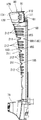
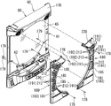
図1は遊技機の外枠の一側に本体枠が開かれその本体枠の一側にガラス扉が開かれた状態を示す斜視図である。図2は遊技機の前側全体を示す正面図である。図3は遊技機を斜め右上前方から示す斜視図である。図4はガラス扉を斜め左上後方から示す斜視図である。図5は遊技機の音響電飾装置を破断して示す側面図である。図6はガラス扉と左右一対の電飾装置とを分離して斜め左上前方から示す斜視図である。図7は左右一対の電飾装置の構成部材を分離して前方から示す斜視図である。図8は左右一対の電飾装置の構成部材を分離して後方から示す斜視図である。図9は電飾装置の遮蔽カバー部材とレンズ部材を分離して前方から示す斜視図である。図10は電飾装置の遮蔽カバー部材とレンズ部材を分離して後方から示す斜視図である。図11はガラス扉の前側に電飾装置が装着された状態の遮蔽カバー部材とレンズ体の関係を示す平断面図である。図12はガラス扉の前側に電飾装置が装着された状態の遮蔽カバー部材と装飾体との関係を示す平断面図である。図13はガラス扉の前側に電飾装置が装着された状態の遮蔽カバー部材とレンズ体の関係を示す側断面図である。なお、説明の便宜上、遊技機において遊技者側を前、反対側を後として説明する。 FIG. 1 is a perspective view showing a state in which a main body frame is opened on one side of an outer frame of the gaming machine and a glass door is opened on one side of the main body frame. FIG. 2 is a front view showing the entire front side of the gaming machine. FIG. 3 is a perspective view showing the gaming machine obliquely from the upper right front. FIG. 4 is a perspective view showing the glass door obliquely from the upper left rear. FIG. 5 is a side view showing the acoustic decoration device of the gaming machine in a cutaway manner. FIG. 6 is a perspective view showing the glass door and the pair of left and right electric decoration devices separated from the upper left front. FIG. 7 is a perspective view showing the constituent members of the pair of left and right electrical decoration devices separated from the front. FIG. 8 is a perspective view showing the constituent members of the pair of left and right electrical decoration devices separated from the rear. FIG. 9 is a perspective view showing the shielding cover member and the lens member of the electric decoration device separated from each other. FIG. 10 is a perspective view showing the shielding cover member and the lens member of the electric decoration device separated from each other. FIG. 11 is a cross-sectional plan view showing the relationship between the shielding cover member and the lens body in a state where the illumination device is mounted on the front side of the glass door. FIG. 12 is a cross-sectional plan view showing the relationship between the shielding cover member and the decorative body in a state in which the illumination device is mounted on the front side of the glass door. FIG. 13 is a side sectional view showing the relationship between the shielding cover member and the lens body in a state where the illumination device is mounted on the front side of the glass door. For convenience of explanation, in the gaming machine, the player side will be described as the front and the opposite side as the back.
[遊技機の概要について]
図1〜図3に示すように、遊技機としてのパチンコ機は、外枠10、本体枠20、遊技盤31、ガラス扉(この発明のガラス扉に相当する)60等を備えて構成されている。
外枠10は、上下左右の枠材によって縦長四角形の枠状に形成され、同外枠10の前側下部には、本体枠20の下面を受ける下受板15を有している。
外枠10の前面の一側には、本体枠開閉用ヒンジ機構19によって本体枠20が前方に開閉可能に装着されている。
[About the outline of gaming machines]
As shown in FIGS. 1 to 3, a pachinko machine as a gaming machine includes an
The
A
また、本体枠20は、前枠体21、遊技盤装着枠30及び機構装着体40を合成樹脂材によって一体成形することで構成されている。
本体枠20の前側に形成された前枠体21は、外枠10前側の下受板15を除く外郭形状に対応する大きさの矩形枠状に形成されている。
Further, the
The
[遊技盤について]
図1に示すように、本体枠20の前枠体21の後部に一体に形成された遊技盤装着枠30には遊技盤31が前方から着脱交換可能に装着されるようになっている。
遊技盤31の盤面(前面)には、外レールと内レールとを備えた案内レール32が設けられ、その案内レール32の内側に遊技領域33が区画形成されている。
遊技盤31には、その遊技領域33内において、遊技に関する役物装置、例えば、センタ役物と呼ばれる役物装置34が装着され、その役物本体35には、その中央部に形成された開口部に表示面を臨ませて図柄表示装置(例えば、液晶表示器、EL表示器,プラズマ表示器,CRT等)36が装着されている。また、遊技盤31の盤面(前面)の遊技領域33内には図示しない入賞器、風車器、誘導釘、ランプ遮蔽カバー部材等の各種の装備品が配設されている。
[About the game board]
As shown in FIG. 1, a
A
In the
図1に示すように、本体枠20の前枠体21の前側において、遊技盤装着枠30よりも下方に位置する前枠体21の前下部領域の一側寄りには、スピーカ装着板26を介してスピーカ(この実施例では低音用スピーカ)27が装着されている。
また、前枠体21前面の下部領域内の上側部分には、遊技盤31の発射通路に向けて球を導く発射レール22が傾斜状に装着されている。
また、前枠体21前面の下部領域内の下側部分には、下前面部材23が装着されている。下前面部材23の前面の略中央部には、下皿24が設けられ、片側寄りには操作ハンドル25が設けられている。
As shown in FIG. 1, on the front side of the
A
In addition, a
[施錠装置について]
図1に示すように、本体枠(前枠体21)20のヒンジ機構と反対側に自由端側の後側には、外枠10に対し本体枠20を施錠する機能と、本体枠20に対し後に詳述するガラス扉60を施錠する機能とを兼ね備えた施錠装置51が装着されている。
すなわち、施錠装置51は、外枠10に設けられた閉止具17に係脱可能に係合して本体枠20を閉じ状態に施錠する上下複数の本体枠施錠フック52と、後述するガラス扉60の自由端側の後側に設けられた閉止具66に係脱可能に係合してガラス扉60を閉じ状態に施錠する上下複数の扉施錠フック53とを備えている。
そして、シリンダー錠55の鍵穴に鍵が挿入されて一方向に回動操作されることで本体枠施錠フック52と外枠10の閉止具17との係合が外れて本体枠20が解錠され、これとは逆方向に回動操作されることで、扉施錠フック53とガラス扉60の閉止具66との係合が外れてガラス扉60が解錠されるようになっている。
なお、シリンダー錠55の前端部は、遊技機の前方から鍵を挿入して解錠操作可能に、前枠体21及び下前面部材23を貫通してその下前面部材23の前面に露出されている。
[About locking device]
As shown in FIG. 1, a function of locking the
That is, the locking
Then, a key is inserted into the keyhole of the
The front end portion of the
[ガラス扉について]
図1に示すように、本体枠(前枠体21)20の前面の一側には、扉開閉用ヒンジ機構50によってガラス扉としてのガラス扉60が前方に開閉可能に装着されている。
図3と図4に示すように、ガラス扉60は、扉本体フレーム61、上皿78、音響電飾装置80、左右一対の電飾装置180を備えて構成されている。
扉本体フレーム61は、プレス加工された単数または複数の金属製フレーム構成部材、例えば複数の鉄板が溶接によって一体化されて構成され、本体枠20の前枠体21の上端から下前面部材23の上縁にわたる部分を覆う大きさに形成されている。
扉本体フレーム61の略中央部には、遊技盤31の遊技領域33を前方から透視可能な略円形の開口窓62が形成されている。また、扉本体フレーム61の後側には開口窓62よりも大きい矩形枠状をなす窓枠63が設けられ、その窓枠63にはガラス板、透明樹脂板等の透明な窓板65が装着されている(図1参照)。
また、扉本体フレーム61の前側の下部には上皿78がそれぞれ装着されている。
[About glass doors]
As shown in FIG. 1, a
As shown in FIGS. 3 and 4, the
The
A substantially
Further, an
[ガラス扉の前側構成について]
図2と図3に示すように、扉本体フレーム61の前面には、その開口窓62の周縁部の上部に沿って、音響電飾装置(トップランプユニット)80が装着されている。この音響電飾装置80は、遊技の進行に同調して音演出や発光装飾(発光演出)を行うためのものであり、遊技機の制御装置(例えば、音制御回路、ランプ制御回路を有する制御基板)によって作動制御されるようになっている。
図3と図5に示すように、音響電飾装置80は、1つにユニット化されて扉本体フレーム61の前側上部にビス等によって装着されている。
また、音響電飾装置80は、ガラス扉6の略全幅にわたる横長状に形成された装置本体81が前カバー体170によって被われることで構成され、装置本体81の左右両側部には、前カバー体170から露出された状態でスピーカカバー95を前側に有するスピーカ97(この実施例では中高音用スピーカ)が装着されている。
また、図5に示すように、装置本体81には、椀形状のリフレクタ体101が横方向に複数配列された状態で形成され、これらリフレクタ体101の中心部には中心部にはプリズム機能を有する光反射体120が組み付けられ、リフレクタ体101の後側には複数の光源111が配置されたランプ基板110が設けられている。
[About the front side configuration of the glass door]
As shown in FIGS. 2 and 3, an acoustic decoration device (top lamp unit) 80 is mounted on the front surface of the door
As shown in FIGS. 3 and 5, the
In addition, the
In addition, as shown in FIG. 5, the apparatus
[電飾装置について]
図6に示すように、扉本体フレーム61の前面には、その開口窓62の周縁部の左右両側部に沿って左右の両電飾装置180が装着されている。これら左右の両電飾装置180は、遊技の進行に同調して発光装飾(発光演出)を行うためのものであり、遊技機の制御装置(例えば、ランプ制御回路を有する制御基板)によって点滅制御されるようになっている。
左右の両電飾装置180は、各1つにユニット化されている。そして、左右の両電飾装置180は、扉本体フレーム61の前方又は/及び後方から締め付けられる複数のビス178、179によって、扉本体フレーム61の前面装着されている。
この実施例において、左右の両電飾装置180は、図6〜図8に示すように、左右対称状をなし、その前側から後側に向けて、装飾体183、遮蔽カバー部材181、レンズ部材200、ランプ基板220及びランプ基板220の後面を絶縁して覆う背面カバー体230を順に備え、これか各部材が相互に組み付けられてユニット化されている。
[About the lighting equipment]
As shown in FIG. 6, left and right
Both the left and right
In this embodiment, as shown in FIGS. 6 to 8, the left and right
[電飾装置の遮蔽カバー部材について]
図9と図13に示すように、遮蔽カバー部材181は、レンズ部材200とは別個に不透明な合成樹脂材によって形成されかつレンズ部材200の表面側を被って保護する剛性を有している。
この実施例において、遮蔽カバー部材181は、前壁部184、内側壁部186及び外側壁部188を一体に備えて平断面略台形状をなしかつ、窓板65の前面から前方に向けて膨出されるようになっている。
また、遮蔽カバー部材181の前壁部184は、その下端から上端に向かうにしたがって遊技者側に接近する下向き傾斜状(あるいは湾曲状)をなすとともに、その内縁部が開口窓62の側部に沿って略円弧状に形成されている。そして、内側壁部186は、前壁部184の内縁部から開口窓62の側部を囲むようにして円弧状をなしかつガラス扉60の窓板65に向けて略直角状をなして形成されている。
また、外側壁部188は、前壁部184の外縁部からガラス扉60の扉本体フレーム61の前側縁に向け形成され、これによって外側に向けて傾斜状をなしている。さらに、外側壁部188は、下端から上端に向けてその幅寸法がしだいに拡大している。
[About shielding cover member of lighting equipment]
As shown in FIGS. 9 and 13, the shielding
In this embodiment, the shielding
Further, the
Moreover, the outer
図9と図13に示すように、遮蔽カバー部材181の前壁部184には、横方向の複数の凹部185が上下方向に所定間隔を隔て凹設されており、これら各凹部185の底面には横長の透孔190が形成されている。これら各凹部185の上下の両壁面は、開口側が広く底側が狭いテーパ状をなしている。
また、遮蔽カバー部材181には、その前壁部184の各凹部185の間において、前壁部184から外側壁部188にわたって横方向に延びる各複数の透孔191が上下方向に所定間隔を隔てて形成されてる。
また、遮蔽カバー部材181の内側壁部186には、各複数の透孔191の横方向の延長上において、横向きU字形の切り欠き状をなす複数の透孔192が上下方向に所定間隔を隔てて形成されてる。
As shown in FIGS. 9 and 13, the
Further, in the shielding
Further, on the
この実施例において、図7と図8に示すように、遮蔽カバー部材181の前壁部184及び外側壁部188の表面(凹部185及び透孔190、191の部分は除く表面)には、遮蔽カバー部材181とは色が異なる装飾体183が係合片、クリップ等の適宜の取付手段182によって装着され、これによって装飾性が高められている(図12参照)。
また、遮蔽カバー部材181は、例えば黒色系の色に形成され、装飾体183の表側意匠面は、例えばメタリック系の色をなしている。
また、この実施例において、図10と図13に示すように、遮蔽カバー部材181の内面(前壁部184、内側壁部186及び外側壁部188の内面)には、各透孔191の間において横方向の補強リブ195が一体に形成されている。
In this embodiment, as shown in FIGS. 7 and 8, the surfaces of the
The shielding
Further, in this embodiment, as shown in FIGS. 10 and 13, the inner surface of the shielding cover member 181 (the inner surfaces of the
[電飾装置のレンズ部材について]
図9と図10に示すように、遮蔽カバー部材181の内側には、透明な合成樹脂材より形成されたレンズ部材200が嵌込まれて装着されている。
このレンズ部材200は、遮蔽カバー部材181の前壁部184、内側壁部186及び外側壁部188の内面に接近して沿う前壁部、内側壁部及び外側壁部を一体に備えて平断面略台形状に形成されている。
図13に示すように、レンズ部材200の前壁部において、遮蔽カバー部材181の各凹部185の対応して凹部201が形成され、その凹部201の底面には、遮蔽カバー部材181の凹部185の透孔190に嵌込まれかつ中実の凹レンズをなすレンズ体211が一体に突設されている。
[Lens member of the illumination device]
As shown in FIGS. 9 and 10, a
The
As shown in FIG. 13, in the front wall portion of the
また、図9と図13に示すように、レンズ部材200には、その前壁部から外側壁部にわたって横方向に延びかつ遮蔽カバー部材181の各複数の透孔191に嵌込まれる中実の凸レンズをなすレンズ212が一体に突設されている。
また、レンズ部材200の内側壁部には、遮蔽カバー部材181の各透孔192に嵌込まれる中実のレンズ体213が一体に突設されている。
また、レンズ部材200の前壁部、内側壁部及び外側壁部の表面(前面)には、遮蔽カバー部材181の各補強リブ195が嵌込まれる凹溝202が形成されている。
Further, as shown in FIGS. 9 and 13, the
In addition, a
Further, a
[電飾装置のランプ基板及び背面カバー体について]
図7、図11及び図13に示すように、レンズ部材200の後側には、各レンズ体211、212、213にそれぞれ対応する位置において、単数、又は複数のランプ、LED等よりなる光源221が配設されたランプ基板220が装着されている。
また、この実施例において、中実の凹レンズをなすレンズ体211に対応する光源221として、例えば単数又は複数の青色LEDが用いられ、凸レンズをなすレンズ212及び平板のレンズ体213に対応する光源221として、例えば単数又は複数の赤色LEDが用いられている。
また、ランプ基板220は、遊技機の制御装置(例えば、ランプ制御回路を有する制御基板)に電気的に接続され、遊技の進行に同調して発光装飾(遊技演出)を行うように、ランプ基板220の多数の光源(多数のLED)221が点滅制御されるようになっている。
また、遮蔽カバー部材181の後側には、同遮蔽カバー部材181にレンズ部材200及びランプ基板220が装着された状態においてその後側を覆う絶縁材(この実施例では合成樹脂材)よりなる背面カバー体230が装着されている。
また、この実施例において、図7に示すように、背面カバー体230の内側縁には、ガラス扉60の開口窓62を構成する円弧状の装飾枠231が一体に形成されている。
[About the lamp board and back cover of the illumination device]
As shown in FIGS. 7, 11, and 13, on the rear side of the
In this embodiment, as the
The
Further, on the rear side of the shielding
Further, in this embodiment, as shown in FIG. 7, an arcuate
また、この実施例において、遮蔽カバー部材181の前壁部184から外側壁部188にわたって横方向に延びる各複数の透孔191において、前壁部184及び外側壁部188の全表面積(各複数の透孔191部分も含む)に対し、各複数の透孔191の合計の開口面積が半分程度あるいはそれ以下に設定されている。
さらに、遮蔽カバー部材181の前壁部184から外側壁部188にわたって横方向に延びる各複数の透孔191に嵌込まれた各レンズ体212において、図11に示すように、前壁部184に位置する前側レンズ部分212aの合計のレンズ面積よりも外側壁部188に位置する外側レンズ部分212bの合計のレンズ面積が適宜に大きく設定されている。
Further, in this embodiment, in each of the plurality of through
Further, in each
[実施例に係る遊技機の作用効果について]
上述したように構成されるこの実施例に係る遊技機において、遊技の進行に同調して遊技機の制御装置(例えば、ランプ制御回路を有する制御基板)から伝達される制御信号によって、左右一対の電飾装置180のランプ基板220の多数の光源(多数のLED)221がそれぞれ点滅制御される。
そして、ランプ基板220の多数の光源(多数のLED)221が発する光は、遮蔽カバー部材181の各透孔190、191、192に嵌込まれた各レンズ体211、212、213を透して出射され、これによって遊技機の前側が電飾される。
[About the effects of the gaming machine according to the embodiment]
In the gaming machine according to this embodiment configured as described above, a pair of left and right is controlled by a control signal transmitted from a control device (for example, a control board having a lamp control circuit) of the gaming machine in synchronization with the progress of the game. A number of light sources (a number of LEDs) 221 on the
The light emitted from a large number of light sources (a large number of LEDs) 221 on the
電飾装置180の遮蔽カバー部材181は、不透明な合成樹脂材より形成されて剛性を有し、その遮蔽カバー部材181によってレンズ部材200の表面側を被って保護することができる。このため、レンズ部材200の表面に、もの(例えば異物)が当たってレンズ部材200が傷つけられたり破損される不具合を防止して耐久性の向上を図ることができる。
また、レンズ部材200に、複数のレンズ体212、213を一体に形成し、これら複数のレンズ体212、213を遮蔽カバー部材181の複数の透孔191、192にそれぞれ嵌込んで露出させることで、複数の透孔191、192の数に対応する複数のレンズ体212、213をそれぞれ個別に形成して組み付けるものと比べ、部品点数や組付工数が少なくてすみ、この分だけコスト低減を図ることができる。
The shielding
In addition, a plurality of
また、図7に示すように、電飾装置180は、遮蔽カバー部材181、レンズ部材200、ランプ基板220、背面カバー体230等の各部材が相互に組み付けられてユニット化されている。
このようにして、電飾装置180をユニット化することによって、ガラス扉60の扉本体フレーム61の前面に電飾装置180を取り付けるための取付基板を装着する手間を省くことができる。
また、電飾装置180をユニット化することによって、遊技機の組み立てラインにおいて、ガラス扉60の扉本体フレーム61の前面に、複数の光源221を有するランプ基板220、レンズ部材200、及び遮蔽カバー部材181の順にそれぞれ個別に装着して組み付ける手間を省くことができる。これによって、遊技機の組み立てに要する時間を短縮化することができる。
また、ガラス扉60の扉本体フレーム61からユニット化された電飾装置180を取り外して保守・点検を容易に行うこともできる。
As shown in FIG. 7, the
Thus, by unitizing the
Further, by unitizing the
In addition, the unitized
また、この実施例においては、図11と図13に示すように、電飾装置180の複数のレンズ体212、213は、レンズ部材200の表面から、遮蔽カバー部材181の複数の透孔191、192の裏側開口部を通し表側開口部まで突出されている。
すなわち、この実施例においては、遮蔽カバー部材181の前壁部184から外側壁部188にわたって形成された透孔191に嵌込まれる複数のレンズ体212の各突出端面は、前壁部184及び外側壁部188の表面と略同一面をなし、内側壁部186に形成された透孔192に嵌込まれる複数のレンズ体213の各突出端面は、内側壁部186の表面と略同一面をなしている。
このようにして、レンズ部材200の表面に一体に突出形成された複数のレンズ体212、213が、遮蔽カバー部材181の表面から突起物となって突出されることがなく、略同一面をなすことで、これら複数の透孔191、192の内周壁面によって良好に保護される。
さらに、複数のレンズ体212、213の前面(突出端面)が複数の透孔191、192の内周壁面によって隠されることもないため、所望とする電飾効果が良好に得られる。
Further, in this embodiment, as shown in FIGS. 11 and 13, the plurality of
That is, in this embodiment, the protruding end surfaces of the plurality of
In this way, the plurality of
Furthermore, since the front surfaces (projecting end surfaces) of the plurality of
また、遮蔽カバー部材181の前壁部184から外側壁部188にわたって透孔191が、内側壁部186に透孔192がそれぞれ個別に形成され、これら各複数の透孔191、192にそれぞれ嵌込まれて露出される各複数のレンズ体212、213がレンズ部材200に一体に形成されている。
そして、これら各複数のレンズ体212、213をそれぞれ透して出射される光によって、遮蔽カバー部材181の前壁部184、外側壁部188及び内側壁部186をそれぞれ個別に電飾することができ、電飾効果を高めることができる。
Further, a through
The
また、この実施例においては、図13に示すように、レンズ部材200の前壁部から外側壁部の表面にわたって突出される横方向の複数のレンズ体212は、中実の凸レンズをなしている。
これによって、光源221が発する光は、中実の凸レンズをなす複数のレンズ体212を透して収束されながら出射されるため、上下方向に所定間隔を隔てた横一直線状の光装飾を施すことができる。
仮に、レンズ部材200の前壁部からレンズ体212が略均一の肉厚で円弧状に突出された場合には、レンズ体212の発光時(光源221が発する光がレンズ体212を透して出射される時)において、レンズ部材200の前壁部前面とレンズ体212の根元部との境界線が前方から視認され、見栄えを悪化させる。これに対し、この実施例では複数のレンズ体212が中実の凸レンズをなすことで、レンズ体212の発光時において、前記境界線の存在が不明となり、前記境界線が原因となる見栄えの悪化を防止することができる。
Further, in this embodiment, as shown in FIG. 13, the plurality of
As a result, the light emitted from the
If the
また、この実施例においては、複数の透孔191、192は、遮蔽カバー部材181の前壁部184、外側壁部188及び内側壁部186において上下方向に所定の間隔を隔てて配列され、レンズ部材200各複数のレンズ体212、213が、各複数の透孔191、192にそれぞれ嵌込まれて露出されている。
このため、例えば、レンズ部材200の各複数のレンズ体212、213の配列順にそれぞれ対応する光源221を点滅制御したり、あるいは、一つおき毎のレンズ体212、213に対応する光源221を点滅制御したり、あるいはレンズ部材200の複数のレンズ体212、213の全てに対応する全ての光源221を点滅制御したり、あるいはこれらの組合せによって光源221を点滅制御することによって多種多様の電飾を施すことができる。
In this embodiment, the plurality of through
For this reason, for example, the
また、この実施例においては、図9と図13に示すように、遮蔽カバー部材181の前側には単数又は複数(図では複数)の凹部185が形成され、これら凹部185の底面に透孔190が形成される一方、レンズ部材200には各凹部185に嵌込まれて露出されるレンズ体211が一体に形成されている。
このようにして、凹部185の底面に形成された透孔190にレンズ部材200のレンズ体211が嵌込まれることによって、レンズ体211を良好に保護することができ、レンズ体211に異物が衝突する不具合を良好に防止することができる。
Further, in this embodiment, as shown in FIGS. 9 and 13, one or a plurality of (in the drawing) recesses 185 are formed on the front side of the shielding
In this way, the
また、この実施例においては、図13に示すように、凹部185の相対する壁面185a、185bは底面側が狭く開口側に向かってしだいに広くなるように対面する一方、レンズ部材200のレンズ体211は中実の凹レンズをなしている。
このため、光源221が発する光が凹レンズよりなるレンズ体211を透して拡散されて出射され、その光の一部が、凹部185の相対する壁面185a、185bにおいて反射される。
言い換えると、光源221が発する光によってレンズ体211の部分と、凹部185の相対する壁面185a、185bの部分とがそれぞれ発光しているかのようにして電飾することができ、電飾効果に優れたものとなる。
Further, in this embodiment, as shown in FIG. 13, the opposing
For this reason, the light emitted from the
In other words, the light emitted from the
また、この実施例においては、図10と図13に示すように、遮蔽カバー部材181の内面には複数の透孔191、192の間において複数の補強リブ195が一体に形成されている。
このため、例えば、不透明な合成樹脂材を成形型に射出して遮蔽カバー部材181を形成した直後において、複数の透孔191、192が原因となって遮蔽カバー部材181が不測に変形する不具合を複数の補強リブ195によって防止することができる。
また、成形型から取り外されて製品となった遮蔽カバー部材181において、複数の透孔191、192の孔回りにおいて遮蔽カバー部材181の強度が部分的に低下し、これによって、遮蔽カバー部材181が不測に変形したり、あるいは破損される不具合を複数の補強リブ195によって防止することができる。
Further, in this embodiment, as shown in FIGS. 10 and 13, a plurality of reinforcing
For this reason, for example, immediately after the opaque synthetic resin material is injected into the mold and the shielding
In addition, in the shielding
また、この実施例においては、図9と図13に示すように、レンズ部材200の前側には複数の補強リブ195が嵌込まれる凹溝202が形成されている。
そして、遮蔽カバー部材181の内面の複数の補強リブ195が、レンズ部材200の前側の凹溝202にそれぞれ嵌込まれることで、遮蔽カバー部材181とレンズ部材200との結合が強固となるとともに、遮蔽カバー部材181及びレンズ部材200の強度が相互に増大される。これによって、遮蔽カバー部材181及びレンズ部材200の不測の変形や破損をより一層良好に防止することができ、耐久性に優れたものとなる。
In this embodiment, as shown in FIGS. 9 and 13, a
Then, the plurality of reinforcing
また、この実施例においては、図7と図12に示すように、遮蔽カバー部材181の前壁部184及び外側壁部188の表面には、同遮蔽カバー部材181とは色が異なる合成樹脂材より形成されかつ遮蔽カバー部材181の内側壁部186の部分を露出させて被う装飾体183が装着されている。
このため、遮蔽カバー部材181自体の色(例えば、黒色系の色)と、その色とは異なる色(例えば、メタリック系の色)の装飾体183によって遮蔽カバー部材181の外観意匠を高めることができ、装飾性に優れたものとなる。
Further, in this embodiment, as shown in FIGS. 7 and 12, the surface of the
For this reason, the appearance design of the shielding
[この発明の他の実施例について]
なお、この発明は前記実施例に限定するものではない。
例えば、前記実施例においては、前枠体21、遊技盤装着枠30及び機構装着体40が合成樹脂材によって一体成形されることで本体枠20が構成される場合を例示したが、遊技盤が着脱可能に装着される遊技盤装着枠が一体に形成されたりあるいは別体の遊技盤装着枠が組み付けられる前枠体が本体枠である場合においてもこの発明を実施することができる。
また、前記実施例においては、ガラス扉60の開口窓62の周縁部の左右両側部に一対の電飾装置180が装着された遊技機である場合を例示したが、電飾装置180を開口窓62の周縁部に沿って略逆U状、略門形状等に構成してもこの発明を実施することができる。
また、スロットマシン等のガラス扉の開口窓の周縁部に沿って電飾装置180が装着される遊技機であってもこの発明を実施することができる。
[Other Embodiments of the Invention]
In addition, this invention is not limited to the said Example.
For example, in the above-described embodiment, the case where the
Moreover, in the said Example, although the case where it was a game machine with which a pair of
Further, the present invention can be implemented even in a gaming machine in which the
60 ガラス扉
180 電飾装置
181 遮蔽カバー部材
184 前壁部
186 内側壁部
188 外側壁部
190、191 透孔
192 内側透孔
200 レンズ部材
211、212、213 レンズ体
220 ランプ基板
221 光源
Claims (3)
前記電飾装置は、
透明又は半透明な合成樹脂材より形成され前記開口窓の周縁部に沿って設けられるレンズ部材と、
遊技の進行に同調して点滅制御されかつ前記レンズ部材に向けて光りを発する光源と、
前記レンズ部材とは別個に不透明な合成樹脂材より形成されかつ同レンズ部材の表面側を被って保護する剛性を有する遮光カバー部材と
を備え、
前記遮光カバー部材には、前記レンズ部材を部分的に露出させる複数の透孔が形成されており、
前記レンズ部材は、
複数のレンズ体を有するとともに、該複数のレンズ体が保護されつつ電飾効果を発揮しうるように、該複数のレンズ体を一体に形成し、これら一体に形成された複数のレンズ体が前記遮光カバー部材に形成された前記複数の透孔にそれぞれ嵌込まれたものである
ことを特徴とする遊技機。 A gaming machine in which an opening window having a window plate through which a gaming area can be seen is formed in a glass door that can be opened and closed on the front side of the gaming machine, and an electric decoration device is mounted along the peripheral edge of the opening window Because
The illumination device is,
A lens member formed from a transparent or translucent synthetic resin material and provided along the peripheral edge of the opening window;
A light source that is flashed in synchronization with the progress of the game and emits light toward the lens member;
A light shielding cover member formed of an opaque synthetic resin material separately from the lens member and having rigidity for covering and protecting the surface side of the lens member ;
With
The light shielding cover member has a plurality of through holes that partially expose the lens member ,
The lens member is
The plurality of lens bodies are integrally formed, and the plurality of lens bodies formed integrally with each other so that the plurality of lens bodies are protected and can exhibit an electric decoration effect while being protected. It is inserted into each of the plurality of through holes formed in the light shielding cover member.
A gaming machine characterized by that.
請求項1に記載の遊技機。 A plurality of lens body is that is protruded from the surface of the lens member to the front opening through the back opening of the plurality of through holes
The gaming machine according to claim 1.
請求項1または2に記載の遊技機。 A lens member, a light-shielding cover member, a lamp substrate having a plurality of light sources, and a back cover body that insulates and covers the rear surface of the lamp substrate are assembled to each other to unitize the lighting device, and the door body frame of the glass door Removably attached to the front
The gaming machine according to claim 1 or 2.
Priority Applications (1)
| Application Number | Priority Date | Filing Date | Title |
|---|---|---|---|
| JP2004196664A JP4517143B2 (en) | 2004-07-02 | 2004-07-02 | Game machine |
Applications Claiming Priority (1)
| Application Number | Priority Date | Filing Date | Title |
|---|---|---|---|
| JP2004196664A JP4517143B2 (en) | 2004-07-02 | 2004-07-02 | Game machine |
Publications (3)
| Publication Number | Publication Date |
|---|---|
| JP2006014980A JP2006014980A (en) | 2006-01-19 |
| JP2006014980A5 JP2006014980A5 (en) | 2009-04-30 |
| JP4517143B2 true JP4517143B2 (en) | 2010-08-04 |
Family
ID=35789729
Family Applications (1)
| Application Number | Title | Priority Date | Filing Date |
|---|---|---|---|
| JP2004196664A Active JP4517143B2 (en) | 2004-07-02 | 2004-07-02 | Game machine |
Country Status (1)
| Country | Link |
|---|---|
| JP (1) | JP4517143B2 (en) |
Cited By (4)
| Publication number | Priority date | Publication date | Assignee | Title |
|---|---|---|---|---|
| JP2016185464A (en) * | 2016-08-03 | 2016-10-27 | 株式会社大一商会 | Pachinko game machine |
| JP2016185460A (en) * | 2016-08-03 | 2016-10-27 | 株式会社大一商会 | Game machine |
| JP2016185459A (en) * | 2016-08-03 | 2016-10-27 | 株式会社大一商会 | Pachinko game machine |
| JP2016185462A (en) * | 2016-08-03 | 2016-10-27 | 株式会社大一商会 | Game machine |
Families Citing this family (36)
| Publication number | Priority date | Publication date | Assignee | Title |
|---|---|---|---|---|
| JP2011224168A (en) * | 2010-04-20 | 2011-11-10 | Daito Giken:Kk | Game machine |
| JP2012170466A (en) * | 2011-02-17 | 2012-09-10 | Kyoraku Sangyo Kk | Pachinko machine |
| JP2013192710A (en) * | 2012-03-19 | 2013-09-30 | Sanyo Product Co Ltd | Game machine |
| JP5580451B2 (en) * | 2013-04-26 | 2014-08-27 | 株式会社ユニバーサルエンターテインメント | Game machine |
| JP2015080704A (en) * | 2013-10-24 | 2015-04-27 | 株式会社ユニバーサルエンターテインメント | Game machine |
| JP5862906B2 (en) * | 2014-02-14 | 2016-02-16 | 株式会社三共 | Game machine |
| JP6654341B2 (en) * | 2014-03-28 | 2020-02-26 | 株式会社平和 | Gaming machine |
| JP5988323B2 (en) * | 2015-04-16 | 2016-09-07 | 株式会社大一商会 | Pachinko machine |
| JP5988324B2 (en) * | 2015-04-16 | 2016-09-07 | 株式会社大一商会 | Game machine |
| JP5988321B2 (en) * | 2015-04-16 | 2016-09-07 | 株式会社大一商会 | Game machine |
| JP5988322B2 (en) * | 2015-04-16 | 2016-09-07 | 株式会社大一商会 | Game machine |
| JP5988325B2 (en) * | 2015-04-16 | 2016-09-07 | 株式会社大一商会 | Pachinko machine |
| JP5988326B2 (en) * | 2015-05-21 | 2016-09-07 | 株式会社大一商会 | Game machine |
| JP5988327B2 (en) * | 2015-06-05 | 2016-09-07 | 株式会社大一商会 | Game machine |
| JP5988328B2 (en) * | 2015-06-05 | 2016-09-07 | 株式会社大一商会 | Game machine |
| JP5988330B2 (en) * | 2015-06-17 | 2016-09-07 | 株式会社大一商会 | Game machine |
| JP5988329B2 (en) * | 2015-06-17 | 2016-09-07 | 株式会社大一商会 | Game machine |
| JP5988331B2 (en) * | 2015-06-17 | 2016-09-07 | 株式会社大一商会 | Pachinko machine |
| JP5988333B2 (en) * | 2015-07-08 | 2016-09-07 | 株式会社大一商会 | Pachinko machine |
| JP5988332B2 (en) * | 2015-07-08 | 2016-09-07 | 株式会社大一商会 | Pachinko machine |
| JP6086626B2 (en) * | 2015-11-30 | 2017-03-01 | 株式会社大一商会 | Game machine |
| JP6179958B2 (en) * | 2015-11-30 | 2017-08-16 | 株式会社大一商会 | Game machine |
| JP6315493B2 (en) * | 2016-07-27 | 2018-04-25 | 株式会社大一商会 | Game machine |
| JP6266052B2 (en) * | 2016-08-03 | 2018-01-24 | 株式会社大一商会 | Game machine |
| JP6188889B2 (en) * | 2016-08-03 | 2017-08-30 | 株式会社大一商会 | Game machine |
| JP6188890B2 (en) * | 2016-08-03 | 2017-08-30 | 株式会社大一商会 | Game machine |
| JP6266053B2 (en) * | 2016-08-03 | 2018-01-24 | 株式会社大一商会 | Game machine |
| JP6315503B2 (en) * | 2016-09-05 | 2018-04-25 | 株式会社大一商会 | Game machine |
| JP6315513B2 (en) * | 2016-09-12 | 2018-04-25 | 株式会社大一商会 | Game machine |
| JP6315514B2 (en) * | 2016-09-12 | 2018-04-25 | 株式会社大一商会 | Game machine |
| JP6315510B2 (en) * | 2016-09-12 | 2018-04-25 | 株式会社大一商会 | Game machine |
| JP6315509B2 (en) * | 2016-09-12 | 2018-04-25 | 株式会社大一商会 | Game machine |
| JP6315512B2 (en) * | 2016-09-12 | 2018-04-25 | 株式会社大一商会 | Game machine |
| JP6315511B2 (en) * | 2016-09-12 | 2018-04-25 | 株式会社大一商会 | Game machine |
| JP6315515B2 (en) * | 2016-09-12 | 2018-04-25 | 株式会社大一商会 | Game machine |
| JP6315516B2 (en) * | 2016-09-12 | 2018-04-25 | 株式会社大一商会 | Game machine |
Citations (5)
| Publication number | Priority date | Publication date | Assignee | Title |
|---|---|---|---|---|
| JPH09225107A (en) * | 1996-02-26 | 1997-09-02 | Pal Co Ltd | Front frame for pachinko machine |
| JPH10277235A (en) * | 1997-04-07 | 1998-10-20 | Universal Hanbai Kk | Ball shooting game machine |
| JPH11178998A (en) * | 1997-12-22 | 1999-07-06 | Toyo Kako Kk | Fancy frame member and device in game machine |
| JP2000176144A (en) * | 1998-12-18 | 2000-06-27 | Adachi Raito Kogyosho:Kk | Pachinko machine |
| JP2001037960A (en) * | 1999-08-03 | 2001-02-13 | Daidoo:Kk | Pachinko machine |
-
2004
- 2004-07-02 JP JP2004196664A patent/JP4517143B2/en active Active
Patent Citations (5)
| Publication number | Priority date | Publication date | Assignee | Title |
|---|---|---|---|---|
| JPH09225107A (en) * | 1996-02-26 | 1997-09-02 | Pal Co Ltd | Front frame for pachinko machine |
| JPH10277235A (en) * | 1997-04-07 | 1998-10-20 | Universal Hanbai Kk | Ball shooting game machine |
| JPH11178998A (en) * | 1997-12-22 | 1999-07-06 | Toyo Kako Kk | Fancy frame member and device in game machine |
| JP2000176144A (en) * | 1998-12-18 | 2000-06-27 | Adachi Raito Kogyosho:Kk | Pachinko machine |
| JP2001037960A (en) * | 1999-08-03 | 2001-02-13 | Daidoo:Kk | Pachinko machine |
Cited By (4)
| Publication number | Priority date | Publication date | Assignee | Title |
|---|---|---|---|---|
| JP2016185464A (en) * | 2016-08-03 | 2016-10-27 | 株式会社大一商会 | Pachinko game machine |
| JP2016185460A (en) * | 2016-08-03 | 2016-10-27 | 株式会社大一商会 | Game machine |
| JP2016185459A (en) * | 2016-08-03 | 2016-10-27 | 株式会社大一商会 | Pachinko game machine |
| JP2016185462A (en) * | 2016-08-03 | 2016-10-27 | 株式会社大一商会 | Game machine |
Also Published As
| Publication number | Publication date |
|---|---|
| JP2006014980A (en) | 2006-01-19 |
Similar Documents
| Publication | Publication Date | Title |
|---|---|---|
| JP4517143B2 (en) | Game machine | |
| JP2006006543A (en) | Electric decoration unit for game machine | |
| JP4366794B2 (en) | Game machine | |
| JP2001276378A (en) | Pinball game machine | |
| JP5938796B2 (en) | Light emitting display unit and gaming machine | |
| JP2008220465A (en) | Pinball game machine | |
| JP2001145727A5 (en) | ||
| JP4670983B2 (en) | Game machine | |
| JPH0919553A (en) | Game machine | |
| JP2006136535A (en) | Game machine | |
| JP4324917B2 (en) | Game machine | |
| JP2013236710A (en) | Game machine | |
| JPH10127865A (en) | Game machine | |
| JPH0910381A (en) | Game machine | |
| JPH1176548A (en) | Game machine | |
| JP6846323B2 (en) | Game machine | |
| JP3925947B2 (en) | Bullet ball machine | |
| JP6736161B2 (en) | Amusement machine | |
| JPH10286358A (en) | Pachinko machine | |
| JP2010063637A (en) | Game machine | |
| JP6153978B2 (en) | Game machine | |
| JP2002143403A (en) | Decorative illumination device | |
| JP2021037212A (en) | Game machine | |
| JP2021037214A (en) | Game machine | |
| JP4922731B2 (en) | Pachinko machine |
Legal Events
| Date | Code | Title | Description |
|---|---|---|---|
| A621 | Written request for application examination |
Free format text: JAPANESE INTERMEDIATE CODE: A621 Effective date: 20060531 |
|
| RD05 | Notification of revocation of power of attorney |
Free format text: JAPANESE INTERMEDIATE CODE: A7425 Effective date: 20080715 |
|
| A521 | Request for written amendment filed |
Free format text: JAPANESE INTERMEDIATE CODE: A523 Effective date: 20090312 |
|
| A131 | Notification of reasons for refusal |
Free format text: JAPANESE INTERMEDIATE CODE: A131 Effective date: 20091208 |
|
| A977 | Report on retrieval |
Free format text: JAPANESE INTERMEDIATE CODE: A971007 Effective date: 20091209 |
|
| A521 | Request for written amendment filed |
Free format text: JAPANESE INTERMEDIATE CODE: A523 Effective date: 20100208 |
|
| RD02 | Notification of acceptance of power of attorney |
Free format text: JAPANESE INTERMEDIATE CODE: A7422 Effective date: 20100208 |
|
| A521 | Request for written amendment filed |
Free format text: JAPANESE INTERMEDIATE CODE: A821 Effective date: 20100208 |
|
| TRDD | Decision of grant or rejection written | ||
| A01 | Written decision to grant a patent or to grant a registration (utility model) |
Free format text: JAPANESE INTERMEDIATE CODE: A01 Effective date: 20100329 |
|
| A01 | Written decision to grant a patent or to grant a registration (utility model) |
Free format text: JAPANESE INTERMEDIATE CODE: A01 |
|
| A61 | First payment of annual fees (during grant procedure) |
Free format text: JAPANESE INTERMEDIATE CODE: A61 Effective date: 20100422 |
|
| FPAY | Renewal fee payment (event date is renewal date of database) |
Free format text: PAYMENT UNTIL: 20130528 Year of fee payment: 3 |
|
| R150 | Certificate of patent or registration of utility model |
Ref document number: 4517143 Country of ref document: JP Free format text: JAPANESE INTERMEDIATE CODE: R150 Free format text: JAPANESE INTERMEDIATE CODE: R150 |
|
| FPAY | Renewal fee payment (event date is renewal date of database) |
Free format text: PAYMENT UNTIL: 20130528 Year of fee payment: 3 |
|
| R250 | Receipt of annual fees |
Free format text: JAPANESE INTERMEDIATE CODE: R250 |
|
| R250 | Receipt of annual fees |
Free format text: JAPANESE INTERMEDIATE CODE: R250 |
|
| R250 | Receipt of annual fees |
Free format text: JAPANESE INTERMEDIATE CODE: R250 |
|
| R250 | Receipt of annual fees |
Free format text: JAPANESE INTERMEDIATE CODE: R250 |
|
| R250 | Receipt of annual fees |
Free format text: JAPANESE INTERMEDIATE CODE: R250 |
|
| R250 | Receipt of annual fees |
Free format text: JAPANESE INTERMEDIATE CODE: R250 |
|
| R250 | Receipt of annual fees |
Free format text: JAPANESE INTERMEDIATE CODE: R250 |
|
| R250 | Receipt of annual fees |
Free format text: JAPANESE INTERMEDIATE CODE: R250 |
|
| R250 | Receipt of annual fees |
Free format text: JAPANESE INTERMEDIATE CODE: R250 |