JP4515552B2 - Feed system and method for epitaxial deposition of silicon using a continuous feed single bubbler - Google Patents
Feed system and method for epitaxial deposition of silicon using a continuous feed single bubbler Download PDFInfo
- Publication number
- JP4515552B2 JP4515552B2 JP12623199A JP12623199A JP4515552B2 JP 4515552 B2 JP4515552 B2 JP 4515552B2 JP 12623199 A JP12623199 A JP 12623199A JP 12623199 A JP12623199 A JP 12623199A JP 4515552 B2 JP4515552 B2 JP 4515552B2
- Authority
- JP
- Japan
- Prior art keywords
- chamber
- chemical
- liquid
- bubbler
- liquid chemical
- Prior art date
- Legal status (The legal status is an assumption and is not a legal conclusion. Google has not performed a legal analysis and makes no representation as to the accuracy of the status listed.)
- Expired - Lifetime
Links
Images


Classifications
-
- C—CHEMISTRY; METALLURGY
- C30—CRYSTAL GROWTH
- C30B—SINGLE-CRYSTAL GROWTH; UNIDIRECTIONAL SOLIDIFICATION OF EUTECTIC MATERIAL OR UNIDIRECTIONAL DEMIXING OF EUTECTOID MATERIAL; REFINING BY ZONE-MELTING OF MATERIAL; PRODUCTION OF A HOMOGENEOUS POLYCRYSTALLINE MATERIAL WITH DEFINED STRUCTURE; SINGLE CRYSTALS OR HOMOGENEOUS POLYCRYSTALLINE MATERIAL WITH DEFINED STRUCTURE; AFTER-TREATMENT OF SINGLE CRYSTALS OR A HOMOGENEOUS POLYCRYSTALLINE MATERIAL WITH DEFINED STRUCTURE; APPARATUS THEREFOR
- C30B25/00—Single-crystal growth by chemical reaction of reactive gases, e.g. chemical vapour-deposition growth
- C30B25/02—Epitaxial-layer growth
- C30B25/14—Feed and outlet means for the gases; Modifying the flow of the reactive gases
-
- Y—GENERAL TAGGING OF NEW TECHNOLOGICAL DEVELOPMENTS; GENERAL TAGGING OF CROSS-SECTIONAL TECHNOLOGIES SPANNING OVER SEVERAL SECTIONS OF THE IPC; TECHNICAL SUBJECTS COVERED BY FORMER USPC CROSS-REFERENCE ART COLLECTIONS [XRACs] AND DIGESTS
- Y10—TECHNICAL SUBJECTS COVERED BY FORMER USPC
- Y10T—TECHNICAL SUBJECTS COVERED BY FORMER US CLASSIFICATION
- Y10T117/00—Single-crystal, oriented-crystal, and epitaxy growth processes; non-coating apparatus therefor
- Y10T117/10—Apparatus
- Y10T117/1004—Apparatus with means for measuring, testing, or sensing
- Y10T117/1008—Apparatus with means for measuring, testing, or sensing with responsive control means
-
- Y—GENERAL TAGGING OF NEW TECHNOLOGICAL DEVELOPMENTS; GENERAL TAGGING OF CROSS-SECTIONAL TECHNOLOGIES SPANNING OVER SEVERAL SECTIONS OF THE IPC; TECHNICAL SUBJECTS COVERED BY FORMER USPC CROSS-REFERENCE ART COLLECTIONS [XRACs] AND DIGESTS
- Y10—TECHNICAL SUBJECTS COVERED BY FORMER USPC
- Y10T—TECHNICAL SUBJECTS COVERED BY FORMER US CLASSIFICATION
- Y10T137/00—Fluid handling
- Y10T137/7287—Liquid level responsive or maintaining systems
Landscapes
- Chemical & Material Sciences (AREA)
- Chemical Kinetics & Catalysis (AREA)
- General Chemical & Material Sciences (AREA)
- Engineering & Computer Science (AREA)
- Crystallography & Structural Chemistry (AREA)
- Materials Engineering (AREA)
- Metallurgy (AREA)
- Organic Chemistry (AREA)
- Chemical Vapour Deposition (AREA)
- Crystals, And After-Treatments Of Crystals (AREA)
Description
【0001】
【発明の属する技術分野】
本発明は、気体化学物質を供給する、供給システム及び方法に関する。より詳しくは、本発明は、気体化学物質をシリコンのエピタキシャル堆積のために供給する、連続的に給送される、単一のバブラーを使用する、供給システム及び方法に関する。
【0002】
【従来の技術】
バブラーは、気体化学物質を供給するために、種々の産業で使用される。一般的には、バブラーは、液体化学物質に浸されたキャリアガス入口管(inlet tube)を有する。その管は、通常、液体化学物質の底面付近に位置する、単一の気体出口を持ち、そのため、キャリアガスの単一の流れが液体化学物質中で泡立つ。いくらかの液体化学物質は、キャリアガスにより気化され、気体化学物質を生成する。
【0003】
半導体産業では、バブラーは、半導体の製作及び処理のための、種々の気体化学物質を供給するために使用される。例えば、バブラーは、単結晶シリコンのエピタキシャル堆積(epitaxial deposition)のための、気体トリクロロシランのような化学物質を供給するために使用される。産業で使用される標準的なバブラーシステムは、デュアルバブラーシステムである。デュアルバブラーシステムは、バッチ工程として働く、2個のバブラーを利用する。すなわち、一方のバブラーは先行(lead)であり、他方は後続(lag)バブラーである。後続バブラーは、最初に使用され、また後続バブラー中の液体の重量が特定のレベルに低下したときに、それはラインから外され、満たされた新しいバブラーに交換される。しかし、先行及び後続バブラーの役割は、バブラーの交換後、逆になる。空のバブラーは化学会社に送られ、続いて清掃され、液体化学物質が充填される。
【0004】
【発明が解決しようとする課題】
デュアルバブラーシステムは、多くの制限を持つ。それを運転することは高価であり、高いメンテナンス及び材料のコストが発生しがちである。環境コストが、それぞれのバッチの後、残留化学物質を処理するために必要である。デュアルシステムは、それを解体して清掃しなくてはならないため、化学的危険への暴露が増大する。デュアルバブラーシステムはそれのバッチの終了時にラインから外さなくてはならないため、システムのサイクルタイムが増大する。更に、デュアルバブラーシステムは、性能の限界がある。汚染物質が、後続バブラーの底部に集まり、また、そこから出て半導体システム内に運ばれ、工程の汚染の危険性を増大させ得る。更に、デュアルバブラーシステムのバッチ運転中に液体の液面の高さ(level)が低下するにつれて、鉄のような金属を含む、バブラーのある構成部品は化学物質の液体中に溶け出すことがあり、またそのような金属は、その外に運ばれて半導体工程を汚染することがある。このように、前述の制限に影響されないバブラーシステムを提供することが望まれる。
【0005】
【課題を解決するための手段】
従って、本発明の目的は、気体化学物質を供給する、改良された供給システム及び方法を提供することである。
【0006】
より詳しくは、本発明の目的は、半導体工程のための気体化学物質を供給するための単一のバブラーを使用する、供給システム及び方法を提供することである。
【0007】
本発明の他の目的は、連続給送システムである、単一バブラーシステムを提供することである。
【0008】
本発明の更なる目的は、コストを低減し、性能を向上させ、及びバブラー交換に起因するサイクルタイムを除去するバブラーシステム及び方法を提供することである。
【0009】
これら及び他の目的は、本発明に従って化学物質の液体を気化させる供給システムにより、提供される。この供給システムは、液体化学物質を保持するチャンバと、キャリアガスをそのチャンバに供給する少なくとも1個の入口管を持つ、単一のバブラーを含む。本システムは、液体化学物質を前記チャンバに給送する液体化学物質供給ラインも含む。出口管(outlet tube)経由で供給される気体化学物質を生成するために、キャリアガスを液体化学物質中で泡立たせる。重量計が、バブラーの重量を計量し、計量した重量に対応する出力信号を生成するために提供される。液体化学物質コントローラは、バブラー及び供給ラインと動作的に結合し、前記出力信号に対応して、液体化学物質の前記バブラー内のあらかじめ選択された液面の高さに充填してそれを連続的に維持し、及びこのように液体化学物質中でキャリアガスを泡立たせることにより、気体化学物質を供給する。
【0010】
【発明の実施の形態】
本発明の他の目的及び利点は、本発明の詳細な説明及び前述の請求項を読むことにより、及び図面を参照することにより明らかになる。
【0011】
図面では同様な構成部品は同様な参照符号により示され、図1は本発明による供給システム10を示す。供給システム10は、液体化学物質を気化させる、単一のバブラー12を含む。液体化学物質は、キャリアガスをその液体化学物質中で泡立たせることにより気化される。特に、バブラー12は、液体化学物質を保持するチャンバ13を有する。入口管14が、バブラーのチャンバ13の上部を通して結合され、及び入口管14の終端がチャンバ13の底部の近傍に位置するよう、チャンバを通して伸びている。出口管16が、半導体装置、この場合はエピタキシャルリアクタ(図示せず)へ気化した化学物質を(例えば25slmから60slmの範囲の流量で)供給するため、バブラーのチャンバ13の上部に結合される。図1に例示の実施形態では、ただ1個の入口管14を備えており、それは液体化学物質及びキャリアガスの両方をバブラーのチャンバ13に供給する。しかし、1個より多い入口管をもつバブラーシステムを使用してよい。
【0012】
特に利益のあることに、本発明のバブラーシステムは、液体化学物質制御システム18経由でバブラーのチャンバ13に液体化学物質の連続給送を備えている。液体化学物質制御システム18は、バブラー12の上流に配置された充填バルブ(fill valve)22に動作的に結合したコントローラ20を含む。液体化学物質の流れは充填バルブ22より調節される。バブラーのチャンバ13内の液体化学物質の液面の高さは、重量計24により指示される。バブラーは重量計24の上に置かれ、重量計24はバブラーのチャンバ13内の液体化学物質の重量をモニタする。特に、重量計24は、バブラーの重量を表わす重量計出力信号を生成し、この出力信号をコントローラ20に送る。コントローラは、重量計出力信号を受信し、それをあらかじめ選択された値と比較し、及びそれに対応する制御信号を生成するように、プログラムされる。出力信号が、このあらかじめ選択された値を下回るとき、コントローラは充填バルブに、開いてバブラーのチャンバ13へ液体化学物質29を供給するための信号を送る。液体化学物質が、大量の化学物質貯蔵タンク(図示せず)に結合された供給ライン25により供給される。充填バルブ22は、あらかじめ選択された値に達したときにコントローラが閉じるための信号を送るまで、開いている。このように、バブラーのチャンバ13が連続的に液体化学物質の交換ができるような、連続フィードバック制御ループが備えられる。
【0013】
バブラーシステム10を運転するために、チャンバ13は、最初に、入口管14経由で液体化学物質が充填される。チャンバは、コントローラ20が充填バルブ22に閉じるための信号を送るまで、充填される。次に、キャリアガス、通常は水素が、入口管14経由でバブラーのチャンバ13に供給される。他には、化学物質の液体及びキャリアガスを、同時にバブラーに供給してもよい。キャリアガスは調節された供給ライン26経由で入口管14に給送される。調節されたライン26は、液体化学物質のライン26への逆流を防止するための逆止め弁28を含む。圧力調節器30もライン26中に配置し、充填工程の連続運転のため、キャリアガスを液体化学物質供給圧力より低い圧力で供給すると好適である。一般的に、水素の圧力は、約1.5から2.8kg/cm2(22から40psi)の範囲になる。充填中、化学物質の液体の圧力は、水素の圧力より0.35から0.70kg/cm2(5から10psi)高いことが好適である。バブラーのチャンバ13内の液体化学物質の温度は、約17.8から18.3°C(64から65°F)の範囲内に維持することが好適である。本発明では、バッチ充填モードで運転する、先行技術のデュアルバブラーシステムにより必要とされたような、通気孔(venting)の必要がなくなる。
【0014】
キャリアガスが入口管14経由でバブラーのチャンバ内に泡立って流れ込む。液体化学物質は以下の方法で気化される。バブラーの動作の原理は、気体の溶解に関するヘンリーの法則だけでなく、気相と液相との間の物質移動にも支配される。例示の実施形態では、水素はキャリアガスとして使用され、トリクロロシラン(以下、TCS)は液体化学物質として使用される。他のキャリアガス及び液体化学物質を、本発明のシステム及び方法で使用できることが、理解されるであろう。水素ガスの泡が、入口管14経由でバブラーのチャンバ13の底部に給送される。好適には、入口管14は0.635cm(1/4’’)径のステンレススチール管で作られる。水素中でのTCSの拡散は、液体と気体との間のTCSの分圧の差に支配される。気相のTCSの定常状態の物質収支(mass balance)は以下のように表現できる。
N(tcs)=Kg(P0−P)
ここで、Kgは気相での物質移動係数;P0は運転温度での液体TCSの蒸気圧;Pは水素中でのTCSの分圧である。
【0015】
上昇する水素ガスの泡は、飽和液体と比較したTCSの分圧を減少させ、液相から気相へのTCSの拡散を引き起こす。水素中でのTCSの平衡濃度は、工程での必要性に基づく、動作圧力及び温度を最適にすることにより、得られる。水素中のTCSの飽和濃度は、水素の圧力が増加すると減少し、また逆の場合も同じである。しかし、水素中のTCSの飽和濃度は、温度が上昇又は下降すると、それぞれ増大または減少する。TCSを伴う水素の平衡飽和(equilibrium saturation)は、本発明のバブラーシステムを以下の条件のもとで動作させることにより、所望のレベルに維持される。
【0016】
(1)液体TCSの液面の高さ(バブラーの容量の約90%)が、バブラーのチャンバ13内で、連続的な充填操作により維持される。液体TCSの液面の高さをこのように高くすることにより、バブラーの中に体積の小さい蒸気の空間を許容し、飽和及び圧力の安定を確実にする。
【0017】
(2)この圧力の安定により、TCSガスの流れをよりよく制御でき、またエピタキシャルシリコン堆積工程のためのTCSの利用率が向上する。
【0018】
(3)ほぼ充填されたTCSのバブラーにより、大きい熱容量(thermal mass)が提供され、ガスの溶解熱により生じる温度上昇が防止される。
【0019】
本発明でのこれら3つの条件の組み合わせは、エピタキシャルシリコンの成長速度の改善された安定性を持つ供給システムを提供し、また単結晶シリコンエピタキシャル堆積工程のコストを減少させる。
【0020】
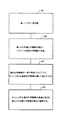
図2に示す本発明に従って、気化した化学物質をエピタキシャルリアクタにシリコンの堆積のため供給する方法。この方法は以下のステップを含む。最初にステップ40で、チャンバ、及び、キャリアガスを前記チャンバ及び出口管に供給する、少なくとも1つの入口で構成される単一バブラーが提供される。次に、42で、チャンバが、あらかじめ選択された液面の高さに、液体化学物質で充填される。キャリアガスは次にステップ44で、液体化学物質を通して泡立てられる。上述のように、液体化学物質の一部は気化され、及び出口管を通してバブラーの外部に運ばれる。特有の長所として、本方法は、ステップ46で、チャンバ内の液体化学物質の液面の高さを、あらかじめ選択された高さに維持するための方法を提供する。
【0021】
【実験】
多くの実験が、本発明に従った供給システムを使用して堆積したシリコンのエピタキシャル層の成長速度を評価するために実施された。気化したTCSの流れの飽和の安定性は、エピタキシャルリアクタ内での堆積したシリコンエピタキシャル層の成長速度の安定性に、直接関係する。図3A及び3Bは、本発明の単一バブラーシステムを使用してエピタキシャルリアクタ内で製作されたウェハーを測定した、それぞれ、抵抗率及び厚さのデータを図解する。リアクタ内の3つの位置、すなわち、リアクタの上部、中央部及び底部の領域を横切る位置に置いたウェハー上に製作されたエピタキシャル層の抵抗率及び厚さを表わす、一連の3回の測定がなされた。一連の測定のそれぞれは、適当な領域に置かれた単一のウェハーで、なされる。合計25のウェハーがテストテストされ、それにより25の測定点が得られた。上部、中央部及び底部の領域での測定は、図3A及び3Bで、それぞれ、”T”、”C”、及び”B”の線により表わされる。
【0022】
図4A及び4Bは、それぞれ、図3A及び3Bのデータの抵抗率及び厚さの測定の標準偏差を示す。抵抗率は、1.530%の標準偏差を、また厚さは1.270%の標準偏差を持ち、これはウェハーに渡っての良好な均一性を示す。示すように、本発明のシステム及び方法は、望ましい抵抗率及び厚さの均一性を持つ、シリコンウェハー上にエピタキシャル層を成長させる。
【0023】
本発明のシステム及び方法を使用して、ウェハー上に成長したエピタキシャル層が、鉄の濃度についてテストされた。上述のように、鉄はバブラーの構成部品から運転中に溶け出し、最後に堆積した層中の汚染物質になることがある。これは、従来技術のデュアルバブラーシステムでは時々問題になる。普通の従来技術のデュアルバブラーシステムを使用して成長した層が、テストされ、3.5×10¹²atoms/cm2の平均の鉄濃度を有することが見出された。本発明を使用して成長した層は、有益な改善である、2.0×1012atoms/cm2の平均の鉄濃度を有する。
【0024】
本発明の特定の実施形態の上述の説明は、図解及び説明の目的で提示したものである。それらは、網羅的となるように又は開示した形態の発明に寸分の違いもなく限定するように意図したものではなく、上述の説明を考慮に入れて多くの修正、実施形態、及び派生が可能である。本発明の範囲は、前述の請求項及びそれらの均等物により定義されるよう意図されている。
【図面の簡単な説明】
【図1】本発明による単一バブラーを使用した供給システムの概略図である。
【図2】本発明による方法のステップの流れ図である。
【図3A】本発明の単一バブラーシステムを使用して製作したウェハーの抵抗率の測定値の図である。
【図3B】本発明の単一バブラーシステムを使用して製作したウェハーの厚さの測定値の図である。
【図4A】図3Aのデータの、抵抗率の測定値の標準偏差を示す図である。
【図4B】図3Bのデータの、厚さの測定値の標準偏差を示す図である。
【符号の説明】
12 単一のバブラー
13 チャンバ
14 入口管
16 出口管
18 液体化学物質制御システム
20 コントローラ
22 充填バルブ
24 重量計
25 供給ライン[0001]
BACKGROUND OF THE INVENTION
The present invention relates to a supply system and method for supplying gaseous chemicals. More particularly, the present invention relates to a delivery system and method using a continuously fed, single bubbler that provides gaseous chemicals for epitaxial deposition of silicon.
[0002]
[Prior art]
Bubblers are used in various industries to supply gaseous chemicals. Generally, a bubbler has a carrier gas inlet tube immersed in a liquid chemical. The tube typically has a single gas outlet, located near the bottom of the liquid chemical, so that a single flow of carrier gas bubbles in the liquid chemical. Some liquid chemicals are vaporized by the carrier gas to produce gaseous chemicals.
[0003]
In the semiconductor industry, bubblers are used to supply a variety of gaseous chemicals for semiconductor fabrication and processing. For example, bubblers are used to supply chemicals such as gaseous trichlorosilane for epitaxial deposition of single crystal silicon. The standard bubbler system used in the industry is the dual bubbler system. The dual bubbler system utilizes two bubblers that act as a batch process. That is, one bubbler is the lead and the other is the lag bubbler. The trailing bubbler is used first, and when the weight of the liquid in the trailing bubbler drops to a certain level, it is removed from the line and replaced with a new filled bubbler. However, the roles of the leading and trailing bubblers are reversed after the bubbler replacement. The empty bubbler is sent to a chemical company which is subsequently cleaned and filled with liquid chemicals.
[0004]
[Problems to be solved by the invention]
The dual bubbler system has many limitations. Operating it is expensive and tends to incur high maintenance and material costs. Environmental costs are required to process residual chemicals after each batch. The dual system increases exposure to chemical hazards because it must be disassembled and cleaned. Since the dual bubbler system must be removed from the line at the end of its batch, the cycle time of the system is increased. Furthermore, the dual bubbler system has performance limitations. Contaminants can collect at the bottom of the subsequent bubbler and out of it can be carried into the semiconductor system, increasing the risk of process contamination. In addition, as the liquid level drops during batch operation of a dual bubbler system, certain bubbler components, including metals such as iron, may dissolve into the chemical liquid. Also, such metals can be carried outside and contaminate the semiconductor process. Thus, it would be desirable to provide a bubbler system that is not affected by the aforementioned limitations.
[0005]
[Means for Solving the Problems]
Accordingly, it is an object of the present invention to provide an improved delivery system and method for delivering gaseous chemicals.
[0006]
More particularly, it is an object of the present invention to provide a delivery system and method that uses a single bubbler for delivering gaseous chemicals for semiconductor processes.
[0007]
Another object of the present invention is to provide a single bubbler system which is a continuous feed system.
[0008]
It is a further object of the present invention to provide a bubbler system and method that reduces cost, improves performance, and eliminates cycle time due to bubbler replacement.
[0009]
These and other objects are provided by a supply system for vaporizing a chemical liquid according to the present invention. The supply system includes a single bubbler having a chamber holding liquid chemicals and at least one inlet tube supplying carrier gas to the chamber. The system also includes a liquid chemical supply line that delivers liquid chemical to the chamber. A carrier gas is bubbled into the liquid chemical to produce a gaseous chemical that is fed via an outlet tube. A weigh scale is provided for weighing the bubbler and generating an output signal corresponding to the weighed weight. A liquid chemical controller is operatively coupled to the bubbler and the supply line, and corresponding to the output signal, fills the liquid chemical to a preselected liquid level in the bubbler and continuously fills it. The gaseous chemical is supplied by maintaining and thus bubbling the carrier gas in the liquid chemical.
[0010]
DETAILED DESCRIPTION OF THE INVENTION
Other objects and advantages of the present invention will become apparent upon reading the detailed description of the invention and the appended claims, and upon reference to the drawings.
[0011]
In the drawings, like components are indicated by like reference numerals, and FIG. The
[0012]
Of particular benefit, the bubbler system of the present invention comprises a continuous delivery of liquid chemicals to the bubbler chamber 13 via the liquid
[0013]
In order to operate the
[0014]
The carrier gas is bubbled into the bubbler chamber via the
N (tcs) = K g (P 0 -P)
Where K g is the mass transfer coefficient in the gas phase; P 0 is the vapor pressure of the liquid TCS at the operating temperature; P is the partial pressure of the TCS in hydrogen.
[0015]
The rising hydrogen gas bubble reduces the TCS partial pressure compared to the saturated liquid and causes the TCS to diffuse from the liquid phase to the gas phase. The equilibrium concentration of TCS in hydrogen is obtained by optimizing the operating pressure and temperature based on the process needs. The saturation concentration of TCS in hydrogen decreases with increasing hydrogen pressure and vice versa. However, the saturation concentration of TCS in hydrogen increases or decreases as the temperature increases or decreases, respectively. The equilibrium saturation of hydrogen with TCS is maintained at the desired level by operating the bubbler system of the present invention under the following conditions.
[0016]
(1) The liquid level of the liquid TCS (about 90% of the bubbler volume) is maintained in the bubbler chamber 13 by a continuous filling operation. By increasing the liquid level of the liquid TCS in this way, a small volume of vapor space is allowed in the bubbler to ensure saturation and pressure stability.
[0017]
(2) This stable pressure allows better control of the TCS gas flow and improves the utilization of TCS for the epitaxial silicon deposition process.
[0018]
(3) The nearly filled TCS bubbler provides a large thermal mass and prevents temperature rise caused by the heat of gas dissolution.
[0019]
The combination of these three conditions in the present invention provides a delivery system with improved stability of the growth rate of epitaxial silicon and reduces the cost of the single crystal silicon epitaxial deposition process.
[0020]
A method for supplying vaporized chemicals to an epitaxial reactor for silicon deposition in accordance with the present invention shown in FIG. The method includes the following steps. Initially, at
[0021]
[Experiment]
A number of experiments were conducted to evaluate the growth rate of epitaxial layers of silicon deposited using a delivery system according to the present invention. The stability of the vaporized TCS flow saturation is directly related to the stability of the growth rate of the deposited silicon epitaxial layer in the epitaxial reactor. 3A and 3B illustrate resistivity and thickness data, respectively, measured on a wafer fabricated in an epitaxial reactor using the single bubbler system of the present invention. A series of three measurements are made that represent the resistivity and thickness of the epitaxial layer fabricated on the wafer at three locations within the reactor, i.e. across the top, middle and bottom regions of the reactor. It was. Each of the series of measurements is made on a single wafer placed in the appropriate area. A total of 25 wafers were test tested, resulting in 25 measurement points. Measurements in the top, middle and bottom regions are represented in FIGS. 3A and 3B by the lines “T”, “C” and “B”, respectively.
[0022]
4A and 4B show the standard deviations of the resistivity and thickness measurements of the data of FIGS. 3A and 3B, respectively. The resistivity has a standard deviation of 1.530% and the thickness has a standard deviation of 1.270%, which indicates good uniformity across the wafer. As shown, the system and method of the present invention grows an epitaxial layer on a silicon wafer with desirable resistivity and thickness uniformity.
[0023]
Using the system and method of the present invention, epitaxial layers grown on the wafer were tested for iron concentration. As mentioned above, iron may melt from the bubbler components during operation and become a contaminant in the last deposited layer. This is sometimes a problem with prior art dual bubbler systems. Layers grown using a common prior art dual bubbler system were tested and found to have an average iron concentration of 3.5 × 10 12 atoms / cm 2 . Layers grown using the present invention have an average iron concentration of 2.0 × 10 12 atoms / cm 2 , which is a beneficial improvement.
[0024]
The foregoing descriptions of specific embodiments of the present invention have been presented for purposes of illustration and description. They are not intended to be exhaustive or to limit the invention to the precise form disclosed, and to the extent that many modifications, embodiments, and derivations are possible in light of the above description. It is. The scope of the present invention is intended to be defined by the following claims and their equivalents.
[Brief description of the drawings]
FIG. 1 is a schematic view of a delivery system using a single bubbler according to the present invention.
FIG. 2 is a flowchart of the steps of the method according to the invention.
FIG. 3A is an illustration of resistivity measurements for a wafer fabricated using the single bubbler system of the present invention.
FIG. 3B is a measurement of the thickness of a wafer fabricated using the single bubbler system of the present invention.
4A is a diagram showing a standard deviation of measured resistivity values of the data in FIG. 3A. FIG.
FIG. 4B is a diagram showing a standard deviation of measured thickness values of the data in FIG. 3B.
[Explanation of symbols]
12 Single bubbler 13
Claims (11)
前記液体化学物質を保持する金属のチャンバ、キャリアガスを前記チャンバに供給する少なくとも1個の入口管、及び前記気体化学物質を供給する1個の出口管を有する単一のバブラーと、
前記チャンバに前記液体化学物質を給送する液体化学物質供給ラインと、
前記バブラーを重量計測し、前記計測重量に対応する出力信号を生成する、重量計測装置と、
前記出力信号に対応して、前記チャンバ中の前記液体化学物質のあらかじめ選択された液面の高さに充填してそれを連続的に維持する、前記チャンバ及び前記供給ラインと動作的に結合した、液体化学物質コントローラとを有し、
前記化学物質は、トリクロロシランであることを特徴とする供給システム。In a supply system that supplies gaseous chemicals by bubbling a carrier gas through liquid chemicals,
A single bubbler having a metal chamber holding the liquid chemical, at least one inlet tube for supplying a carrier gas to the chamber, and one outlet tube for supplying the gaseous chemical;
A liquid chemical supply line for feeding the liquid chemical to the chamber;
A weight measuring device that weighs the bubbler and generates an output signal corresponding to the measured weight;
In response to the output signal, the chamber and the supply line are operatively coupled to fill and maintain a preselected liquid level height of the liquid chemical in the chamber. A liquid chemical controller and
The supply system , wherein the chemical substance is trichlorosilane .
金属のチャンバ、キャリアガスを前記チャンバに給送する少なくとも1個の入口、及び出口管を有する単一のバブラーを準備するステップと、
前記チャンバを、液体化学物質で、あらかじめ選択された液面の高さに充填するステップと、
前記液体化学物質を通してキャリアガスを泡立たせ、それにより前記液体化学物質の一部を気化するステップと、
重量計測装置によって、前記バブラーの重量を計測し、前記計測重量に対応する出力信号を生成するステップと、
前記チャンバ中の前記液体化学物質の前記液面の高さを、前記出力信号に対応して、前記あらかじめ選択された液面の高さに連続的に維持するステップとを有し、
前記化学物質は、トリクロロシランであることを特徴とする方法。In a method for supplying vaporized chemical substances,
Providing a single bubbler having a metal chamber, at least one inlet for delivering a carrier gas to the chamber, and an outlet tube;
Filling the chamber with a liquid chemical to a preselected level of liquid level;
Bubbling a carrier gas through the liquid chemical, thereby vaporizing a portion of the liquid chemical;
Measuring a weight of the bubbler by a weight measuring device, and generating an output signal corresponding to the measured weight;
Continuously maintaining the liquid level height of the liquid chemical in the chamber at the preselected liquid level height in response to the output signal ;
The method according to claim 1, wherein the chemical substance is trichlorosilane .
Applications Claiming Priority (2)
| Application Number | Priority Date | Filing Date | Title |
|---|---|---|---|
| US09/049537 | 1998-03-27 | ||
| US09/049,537 US6123765A (en) | 1998-03-27 | 1998-03-27 | Continuously fed single bubbler for epitaxial deposition of silicon |
Publications (2)
| Publication Number | Publication Date |
|---|---|
| JPH11349397A JPH11349397A (en) | 1999-12-21 |
| JP4515552B2 true JP4515552B2 (en) | 2010-08-04 |
Family
ID=21960344
Family Applications (1)
| Application Number | Title | Priority Date | Filing Date |
|---|---|---|---|
| JP12623199A Expired - Lifetime JP4515552B2 (en) | 1998-03-27 | 1999-03-29 | Feed system and method for epitaxial deposition of silicon using a continuous feed single bubbler |
Country Status (2)
| Country | Link |
|---|---|
| US (1) | US6123765A (en) |
| JP (1) | JP4515552B2 (en) |
Families Citing this family (10)
| Publication number | Priority date | Publication date | Assignee | Title |
|---|---|---|---|---|
| GB9929279D0 (en) * | 1999-12-11 | 2000-02-02 | Epichem Ltd | An improved method of and apparatus for the delivery of precursors in the vapour phase to a plurality of epitaxial reactor sites |
| US20020064961A1 (en) * | 2000-06-26 | 2002-05-30 | Applied Materials, Inc. | Method and apparatus for dissolving a gas into a liquid for single wet wafer processing |
| US6736987B1 (en) * | 2000-07-12 | 2004-05-18 | Techbank Corporation | Silicon etching apparatus using XeF2 |
| US6837263B2 (en) * | 2000-10-20 | 2005-01-04 | Distaview Corporation | Liquid level control system |
| US6644344B2 (en) * | 2001-05-11 | 2003-11-11 | Ashland, Inc. | Method and apparatus for metering a flow rate of a fluid |
| US20060121192A1 (en) * | 2004-12-02 | 2006-06-08 | Jurcik Benjamin J | Liquid precursor refill system |
| WO2006113065A1 (en) * | 2005-04-12 | 2006-10-26 | E.I. Du Pont De Nemours And Company | System for accurately weighing solids and control mechanism for same |
| GB0718686D0 (en) * | 2007-09-25 | 2007-10-31 | P2I Ltd | Vapour delivery system |
| US8960220B2 (en) * | 2011-04-18 | 2015-02-24 | Ceres Technologies, Inc. | Liquid mass measurement and fluid transmitting apparatus |
| JP7230877B2 (en) * | 2020-04-20 | 2023-03-01 | 株式会社Sumco | Epitaxial wafer manufacturing system and epitaxial wafer manufacturing method |
Family Cites Families (14)
| Publication number | Priority date | Publication date | Assignee | Title |
|---|---|---|---|---|
| US4615720A (en) * | 1983-11-17 | 1986-10-07 | Owens-Corning Fiberglas Corporation | Method and apparatus for melting glass |
| US5219224A (en) * | 1986-02-26 | 1993-06-15 | Micro Chemical, Inc. | Programmable apparatus and method for delivering microingredient feed additives to animals by weight |
| JPH01215793A (en) * | 1988-02-24 | 1989-08-29 | Toshiba Ceramics Co Ltd | Apparatus for chemical vapor deposition |
| US4979545A (en) * | 1988-10-31 | 1990-12-25 | Olin Corporation | Bubbler container automatic refill system |
| JPH0372078A (en) * | 1989-08-09 | 1991-03-27 | Anelva Corp | Method and device for forming thin film |
| US5078922A (en) * | 1990-10-22 | 1992-01-07 | Watkins-Johnson Company | Liquid source bubbler |
| US5335185A (en) * | 1992-04-24 | 1994-08-02 | Halliburton Company | Automatic level control system and method |
| US5402834A (en) * | 1992-11-25 | 1995-04-04 | Merck & Co., Inc. | Solution preparation system |
| JPH06196419A (en) * | 1992-12-24 | 1994-07-15 | Canon Inc | Chemical vapor deposition apparatus and semiconductor device manufacturing method using the same |
| JPH06267870A (en) * | 1993-03-16 | 1994-09-22 | Canon Inc | Deposited film forming method and apparatus |
| US5878793A (en) * | 1993-04-28 | 1999-03-09 | Siegele; Stephen H. | Refillable ampule and method re same |
| JP2996101B2 (en) * | 1994-08-05 | 1999-12-27 | 信越半導体株式会社 | Liquid source gas supply method and apparatus |
| MX9701486A (en) * | 1995-06-28 | 1997-05-31 | Gen Electric | Washing machine fill control system. |
| JPH0966228A (en) * | 1995-08-31 | 1997-03-11 | Sony Corp | Liquid raw material supply device |
-
1998
- 1998-03-27 US US09/049,537 patent/US6123765A/en not_active Expired - Lifetime
-
1999
- 1999-03-29 JP JP12623199A patent/JP4515552B2/en not_active Expired - Lifetime
Also Published As
| Publication number | Publication date |
|---|---|
| US6123765A (en) | 2000-09-26 |
| JPH11349397A (en) | 1999-12-21 |
Similar Documents
| Publication | Publication Date | Title |
|---|---|---|
| TWI801420B (en) | Apparatus for dispensing a vapor phase reactant to a reaction chamber and related methods | |
| JP5449221B2 (en) | Method for bulk feeding organometallic precursors to multiple epitaxial reactor sections | |
| US4517220A (en) | Deposition and diffusion source control means and method | |
| US10087523B2 (en) | Vapor delivery method and apparatus for solid and liquid precursors | |
| EP0931861B1 (en) | Method and apparatus for feeding a gas for epitaxial growth | |
| JP4515552B2 (en) | Feed system and method for epitaxial deposition of silicon using a continuous feed single bubbler | |
| US7025337B2 (en) | Method for maintaining a constant level of fluid in a liquid vapor delivery system | |
| TWI404820B (en) | Method and equipment | |
| TWI568882B (en) | Steam delivery device, method of manufacture, and method of use thereof | |
| JPH11317374A (en) | Apparatus and method for continuous gas saturation | |
| CN101506623B (en) | Method for measuring precursor amounts in bubbler sources | |
| US10480071B2 (en) | Continuous distillation trichlorosilane vaporization supply apparatus | |
| JPH06295862A (en) | Compound semiconductor fabrication system and organic metal material vessel | |
| JP3331636B2 (en) | Water generation method | |
| US10752995B2 (en) | Material delivery system and method | |
| JP2000221073A (en) | In-tank liquid level detection device for substrate treating device | |
| JPH06316765A (en) | Vaporizer for liquid material | |
| CN113813619A (en) | Steam generation device and method | |
| JP2000218143A (en) | Chemical mixing equipment and supply amount control method | |
| KR20260032437A (en) | Substrate processing method, semiconductor device manufacturing method, substrate processing device and program | |
| CN117839464A (en) | TCS bubbling conveying system and control method thereof | |
| JP2026020116A (en) | Precursor supply tank | |
| KR20230070020A (en) | A method for estimating the remaining amount of a solid raw material, a method for forming a film, an apparatus for supplying a raw material gas, and an apparatus for performing film formation | |
| JPH03196533A (en) | Gas feeder |
Legal Events
| Date | Code | Title | Description |
|---|---|---|---|
| A621 | Written request for application examination |
Free format text: JAPANESE INTERMEDIATE CODE: A621 Effective date: 20060328 |
|
| A977 | Report on retrieval |
Free format text: JAPANESE INTERMEDIATE CODE: A971007 Effective date: 20081028 |
|
| A131 | Notification of reasons for refusal |
Free format text: JAPANESE INTERMEDIATE CODE: A131 Effective date: 20081104 |
|
| A601 | Written request for extension of time |
Free format text: JAPANESE INTERMEDIATE CODE: A601 Effective date: 20090204 |
|
| A602 | Written permission of extension of time |
Free format text: JAPANESE INTERMEDIATE CODE: A602 Effective date: 20090209 |
|
| A521 | Request for written amendment filed |
Free format text: JAPANESE INTERMEDIATE CODE: A523 Effective date: 20090507 |
|
| A131 | Notification of reasons for refusal |
Free format text: JAPANESE INTERMEDIATE CODE: A131 Effective date: 20091029 |
|
| A521 | Request for written amendment filed |
Free format text: JAPANESE INTERMEDIATE CODE: A523 Effective date: 20091215 |
|
| TRDD | Decision of grant or rejection written | ||
| A01 | Written decision to grant a patent or to grant a registration (utility model) |
Free format text: JAPANESE INTERMEDIATE CODE: A01 Effective date: 20100422 |
|
| A01 | Written decision to grant a patent or to grant a registration (utility model) |
Free format text: JAPANESE INTERMEDIATE CODE: A01 |
|
| A61 | First payment of annual fees (during grant procedure) |
Free format text: JAPANESE INTERMEDIATE CODE: A61 Effective date: 20100513 |
|
| R150 | Certificate of patent or registration of utility model |
Free format text: JAPANESE INTERMEDIATE CODE: R150 |
|
| FPAY | Renewal fee payment (event date is renewal date of database) |
Free format text: PAYMENT UNTIL: 20130521 Year of fee payment: 3 |
|
| R250 | Receipt of annual fees |
Free format text: JAPANESE INTERMEDIATE CODE: R250 |
|
| R250 | Receipt of annual fees |
Free format text: JAPANESE INTERMEDIATE CODE: R250 |
|
| R250 | Receipt of annual fees |
Free format text: JAPANESE INTERMEDIATE CODE: R250 |
|
| R250 | Receipt of annual fees |
Free format text: JAPANESE INTERMEDIATE CODE: R250 |
|
| R250 | Receipt of annual fees |
Free format text: JAPANESE INTERMEDIATE CODE: R250 |
|
| R250 | Receipt of annual fees |
Free format text: JAPANESE INTERMEDIATE CODE: R250 |
|
| EXPY | Cancellation because of completion of term |