JP4514937B2 - Ball joint - Google Patents
Ball joint Download PDFInfo
- Publication number
- JP4514937B2 JP4514937B2 JP2000358130A JP2000358130A JP4514937B2 JP 4514937 B2 JP4514937 B2 JP 4514937B2 JP 2000358130 A JP2000358130 A JP 2000358130A JP 2000358130 A JP2000358130 A JP 2000358130A JP 4514937 B2 JP4514937 B2 JP 4514937B2
- Authority
- JP
- Japan
- Prior art keywords
- housing
- bearing seat
- wear
- opening
- resistant material
- Prior art date
- Legal status (The legal status is an assumption and is not a legal conclusion. Google has not performed a legal analysis and makes no representation as to the accuracy of the status listed.)
- Expired - Fee Related
Links
Images
Classifications
-
- F—MECHANICAL ENGINEERING; LIGHTING; HEATING; WEAPONS; BLASTING
- F16—ENGINEERING ELEMENTS AND UNITS; GENERAL MEASURES FOR PRODUCING AND MAINTAINING EFFECTIVE FUNCTIONING OF MACHINES OR INSTALLATIONS; THERMAL INSULATION IN GENERAL
- F16C—SHAFTS; FLEXIBLE SHAFTS; ELEMENTS OR CRANKSHAFT MECHANISMS; ROTARY BODIES OTHER THAN GEARING ELEMENTS; BEARINGS
- F16C11/00—Pivots; Pivotal connections
- F16C11/04—Pivotal connections
- F16C11/06—Ball-joints; Other joints having more than one degree of angular freedom, i.e. universal joints
- F16C11/0619—Ball-joints; Other joints having more than one degree of angular freedom, i.e. universal joints the female part comprising a blind socket receiving the male part
- F16C11/0623—Construction or details of the socket member
- F16C11/0628—Construction or details of the socket member with linings
- F16C11/0633—Construction or details of the socket member with linings the linings being made of plastics
-
- F—MECHANICAL ENGINEERING; LIGHTING; HEATING; WEAPONS; BLASTING
- F16—ENGINEERING ELEMENTS AND UNITS; GENERAL MEASURES FOR PRODUCING AND MAINTAINING EFFECTIVE FUNCTIONING OF MACHINES OR INSTALLATIONS; THERMAL INSULATION IN GENERAL
- F16C—SHAFTS; FLEXIBLE SHAFTS; ELEMENTS OR CRANKSHAFT MECHANISMS; ROTARY BODIES OTHER THAN GEARING ELEMENTS; BEARINGS
- F16C11/00—Pivots; Pivotal connections
- F16C11/04—Pivotal connections
- F16C11/06—Ball-joints; Other joints having more than one degree of angular freedom, i.e. universal joints
- F16C11/0619—Ball-joints; Other joints having more than one degree of angular freedom, i.e. universal joints the female part comprising a blind socket receiving the male part
- F16C11/0623—Construction or details of the socket member
- F16C11/0647—Special features relating to adjustment for wear or play; Wear indicators
-
- F—MECHANICAL ENGINEERING; LIGHTING; HEATING; WEAPONS; BLASTING
- F16—ENGINEERING ELEMENTS AND UNITS; GENERAL MEASURES FOR PRODUCING AND MAINTAINING EFFECTIVE FUNCTIONING OF MACHINES OR INSTALLATIONS; THERMAL INSULATION IN GENERAL
- F16C—SHAFTS; FLEXIBLE SHAFTS; ELEMENTS OR CRANKSHAFT MECHANISMS; ROTARY BODIES OTHER THAN GEARING ELEMENTS; BEARINGS
- F16C11/00—Pivots; Pivotal connections
- F16C11/04—Pivotal connections
- F16C11/06—Ball-joints; Other joints having more than one degree of angular freedom, i.e. universal joints
- F16C11/0666—Sealing means between the socket and the inner member shaft
- F16C11/0671—Sealing means between the socket and the inner member shaft allowing operative relative movement of joint parts due to flexing of the sealing means
-
- F—MECHANICAL ENGINEERING; LIGHTING; HEATING; WEAPONS; BLASTING
- F16—ENGINEERING ELEMENTS AND UNITS; GENERAL MEASURES FOR PRODUCING AND MAINTAINING EFFECTIVE FUNCTIONING OF MACHINES OR INSTALLATIONS; THERMAL INSULATION IN GENERAL
- F16C—SHAFTS; FLEXIBLE SHAFTS; ELEMENTS OR CRANKSHAFT MECHANISMS; ROTARY BODIES OTHER THAN GEARING ELEMENTS; BEARINGS
- F16C2204/00—Metallic materials; Alloys
- F16C2204/20—Alloys based on aluminium
-
- F—MECHANICAL ENGINEERING; LIGHTING; HEATING; WEAPONS; BLASTING
- F16—ENGINEERING ELEMENTS AND UNITS; GENERAL MEASURES FOR PRODUCING AND MAINTAINING EFFECTIVE FUNCTIONING OF MACHINES OR INSTALLATIONS; THERMAL INSULATION IN GENERAL
- F16C—SHAFTS; FLEXIBLE SHAFTS; ELEMENTS OR CRANKSHAFT MECHANISMS; ROTARY BODIES OTHER THAN GEARING ELEMENTS; BEARINGS
- F16C2326/00—Articles relating to transporting
- F16C2326/01—Parts of vehicles in general
- F16C2326/05—Vehicle suspensions, e.g. bearings, pivots or connecting rods used therein
-
- F—MECHANICAL ENGINEERING; LIGHTING; HEATING; WEAPONS; BLASTING
- F16—ENGINEERING ELEMENTS AND UNITS; GENERAL MEASURES FOR PRODUCING AND MAINTAINING EFFECTIVE FUNCTIONING OF MACHINES OR INSTALLATIONS; THERMAL INSULATION IN GENERAL
- F16C—SHAFTS; FLEXIBLE SHAFTS; ELEMENTS OR CRANKSHAFT MECHANISMS; ROTARY BODIES OTHER THAN GEARING ELEMENTS; BEARINGS
- F16C2326/00—Articles relating to transporting
- F16C2326/20—Land vehicles
- F16C2326/24—Steering systems, e.g. steering rods or columns
-
- Y—GENERAL TAGGING OF NEW TECHNOLOGICAL DEVELOPMENTS; GENERAL TAGGING OF CROSS-SECTIONAL TECHNOLOGIES SPANNING OVER SEVERAL SECTIONS OF THE IPC; TECHNICAL SUBJECTS COVERED BY FORMER USPC CROSS-REFERENCE ART COLLECTIONS [XRACs] AND DIGESTS
- Y10—TECHNICAL SUBJECTS COVERED BY FORMER USPC
- Y10T—TECHNICAL SUBJECTS COVERED BY FORMER US CLASSIFICATION
- Y10T403/00—Joints and connections
- Y10T403/32—Articulated members
- Y10T403/32606—Pivoted
- Y10T403/32631—Universal ball and socket
- Y10T403/32737—Universal ball and socket including liner, shim, or discrete seat
Landscapes
- Engineering & Computer Science (AREA)
- General Engineering & Computer Science (AREA)
- Mechanical Engineering (AREA)
- Pivots And Pivotal Connections (AREA)
Description
【0001】
【発明の属する技術分野】
本発明は、アルミニウム合金製のハウジングを有するボールジョイントに関する。
【0002】
【従来の技術】
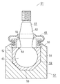
従来、この種のボールジョイントとしては、図2に示す構成が知られている。
【0003】
この図2に示すボールジョイント51は、一端に挿入孔52を開口し他端に底部53が閉塞して一体的に設けられたアルミニウム合金製のソケット54、および、このソケット54の挿入孔52にこの挿入孔52の周縁が内方にかしめ変形されることにより固定されて取り付けられ内周に開口部55を開口するプラグ56を有し、一端に開口部55を開口する有底円筒状のハウジング57を備えている。そして、このハウジング57内には、開口部55に対向する挿通孔58を有したベアリングシート59が収容されている。また、ベアリングシート59内には、開口部55および挿通孔58を挿通するボールスタッド61の軸部62の一端の径大の球頭部63が摺動可能に内包されている。そして、ボールジョイント51は、ボールスタッド61の軸部62に一端が嵌着するとともに他端がハウジング57のプラグ56に嵌着する筒状のダストカバー65が取り付けられている。
【0004】
【発明が解決しようとする課題】
しかしながら、上記図2に示す従来のボールジョイント51では、例えば長期使用によりダストカバー65が破損して泥水などがハウジング57内に浸入した場合に、ボールスタッド61、ベアリングシート59およびハウジング57間に介在する泥水などによりボールスタッド61より軟質のベアリングシート59およびハウジング57が早期に摩耗し、しいてはハウジング57が破損するなどのおそれもあり、ボールジョイント51としての機能が損なわれる。このため、ボールジョイント51を例えば自動車の懸架装置や操舵装置に使用した場合には、車輪からの衝撃を吸収できなくなったり操舵できなくなるなどのおそれがある問題がある。
【0005】
本発明は、このような問題点に鑑みなされたもので、アルミニウム合金製のハウジングの早期摩耗を抑制するボールジョイントを提供することを目的とする。
【0006】
【課題を解決するための手段】
請求項1記載のボールジョイントは、一端に開口部を開口するとともに他端が底部にて閉塞され前記開口部に連続する内室を有しアルミニウム合金にて有底筒状に形成されたハウジングと、このハウジングの内室内に収容され前記開口部に対向する挿通孔を開口したベアリングシートと、このベアリングシートに摺動可能に内包される外周面が略球面状の球頭部およびこの球頭部に連続して設けられ前記ベアリングシートの挿通孔および前記ハウジングの開口部を挿通する軸部を有したボールスタッドと、前記ハウジングより硬質の材料にて形成された耐摩耗材とを具備し、前記ハウジングの底部は、前記開口部に対向する平面状の内底面部およびこの内底面部に連続し前記開口部に向けて拡径する傾斜した傾斜面部を有し、前記ベアリングシートは、前記内底面部に対向して当接する底板部およびこの底板部に連続し前記傾斜面部に対向して当接する傾斜板部とを有し、前記耐摩耗材は、前記ハウジングの底部の内底面部と前記ベアリングシートの底板部との間に介在されるものである。
【0007】
そして、アルミニウム合金製のハウジングの底部の開口部に対向する平面状の内底面部と、ボールスタッドの球頭部を摺動可能に内包してハウジングの内室内に収容されるベアリングシートのハウジングの内底面部に対向して当接する底板部との間に、ハウジングより硬質の材料にて形成した耐摩耗材を介在させることにより、ボールスタッドに加わる外部からの荷重はハウジングの内底面部に連続し開口部に向けて拡径する傾斜した傾斜面部に対向して当接するベアリングシートの底板部に連続する傾斜板部にて吸収し、例えば泥水などが浸入してベアリングシートが早期摩耗しても、比較的荷重が掛かり難いハウジングの内底面部に位置して介在した耐摩耗材にてハウジングの早期摩耗が効率よく防止され、ハウジングの破損などによる自在継手としての機能が完全に損失してしまうことを防止する。
【0008】
請求項2記載のボールジョイントは、請求項1記載のボールジョイントにおいて、ハウジングは、ベアリングシートと対向する面に耐摩耗材が前記ベアリングシートに当接する状態で収容し位置決め保持する凹部を有したものである。
【0009】
そして、ハウジングのベアリングシートと対向する面に、耐摩耗材をベアリングシートに当接する状態で収容して位置決め保持する凹部を設けることにより、ボールスタッドの球頭部が摺動するなどの外部から応力が作用しても凹部という簡単な構造で耐摩耗材が移動せずに位置決めされ、耐摩耗材の移動によるベアリングシートやハウジングの早期摩耗が防止される。
【0010】
請求項3記載のボールジョイントは、請求項1または2記載のボールジョイントにおいて、耐摩耗材は、ステンレス鋼であるものである。
【0011】
そして、耐摩耗材としてステンレス鋼を用いることにより、ハウジングよりも硬質で比較的加工が容易で容易に製造されるとともに、例え泥水が浸入しても腐食を生じず、腐食によるベアリングシートおよびハウジングの早期摩耗が防止される。
【0012】
【発明の実施の形態】
以下、本発明の実施の一形態としてボールジョイントの構成を図面を参照して説明する。
【0013】
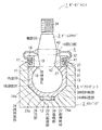
図1において、1はボールジョイントで、このボールジョイント1は、アルミニウム合金製の略有底円筒状のハウジング2と、例えば鋼鉄製のボールスタッド3と、合成樹脂製のベアリングシート4と、ゴムや軟質合成樹脂にて略円筒状に形成されたダストカバー5とを備え、例えば自動車の懸架装置や操舵装置などに用いられる。
【0014】
そして、ハウジング2は、アルミニウム合金にて鍛造成形され、一端に挿入孔11を開口し他端に底部12が閉塞して一体に設けられた有底円筒状のソケット13と、このソケット13の挿入孔11に取り付けられ開口部14を開口するプラグ15とを備えている。
【0015】
また、プラグ15は、開口部14を開口する円筒状の筒状部17およびこの筒状部17の両端縁に外方に向けて鍔状に突出する一対のフランジ部18,18を有し、フランジ部18,18間の筒状部17の外周面には周方向に凹溝状の係止凹部19が設けられている。
【0016】
さらに、ソケット13には、挿入孔11側の内周面にプラグ15のフランジ部18の外径と略同寸法となるように径大に形成されて当接部21が段差状に形成されている。また、ソケット13の挿入孔11の縁には、ソケット13より肉薄で同軸上に円筒状に設けられ内方に向けてかしめ変形されることによりプラグ15のフランジ部18を係止固定するかしめ部22が設けられている。さらに、ソケット13の底部12には、挿入孔11に一体的に取り付けられるプラグ15の開口部14に略平行な平面の底面23aを有する平面状の内底面部23およびこの内底面部23の底面23aに連続し開口部14に向けて拡径状に拡開する傾斜した傾斜面24aを有する傾斜面部24を有している。
【0017】
また、ソケット13には、内底面部23の略中央に上方である挿入孔11に向けて開口する凹部26が設けている。さらに、この凹部26内には、例えばステンレス鋼にてリング状に形成された耐摩耗材27が収容されている。なお、耐摩耗材27は、リング状に限らず、不連続リング状、皿ばね状、皿状、シート状など、いずれの形状でもよいが、荷重が掛かった際に荷重を効率よく分散できる形状が好ましい。また、耐摩耗材27は、凹部26に収容された状態で内底面部23の底面23aから突出することなくかつ上端縁が底面23aの上面に略位置するように配設されている。
【0018】
そして、ハウジング2は、ソケット13の挿入孔11からプラグ15のフランジ部18の周縁が当接部21に当接するまで挿入され、かしめ部22が内方にかしめ変形されてプラグ15のフランジ部18が係止固定され、一端に開口部14を開口し内側に開口部14に連続する内室29を区画して有底円筒状に組立形成される。なお、ハウジング2のソケット13の側面や底部12の下面に、図示しない雄ねじや雌ねじを有した連結部が設けられている。
【0019】
また、ボールスタッド3は、略球状の球頭部31と、この球頭部31に連続しハウジング2の開口部14を挿通する小径部32を介して略円柱状の軸部33が一体に形成されている。なお、球頭部31は、軸部33より径大に形成されている。そして、軸部33の先端部には、雄ねじ部34が設けられている。
【0020】
さらに、ベアリングシート4は、ポリアセタール樹脂やポリウレタン樹脂、ポリアミド樹脂などの良好なベアリング特性を有する耐荷重性の高い剛性および弾性を有した合成樹脂にて形成されている。そして、ベアリングシート4は、一端にボールスタッド3の球頭部31が挿入されて軸部33を挿通し開口部14に対向する挿通孔36を開口する円筒状の胴体部37、この胴体部37の他端に設けられ外面がハウジング2の傾斜面部24の傾斜面24aに対向して当接する傾斜板部38、および、この傾斜板部38の先端部に胴体部37の他端を閉塞して連続して設けられ外面がハウジング2の内底面部23に対向して内底面部23および耐摩耗材27に当接する底板部39とを有し、内面が球頭部31に対応した略球面状で球頭部31を摺動可能に内包する有底円筒形のブロック状に成形されている。なお、ベアリングシート4は、底板部39の最肉薄部分が傾斜板部38の最肉薄部分と略同厚さ寸法に形成されている。
【0021】
また、ダストカバー5は、一端に略環状でハウジング2のプラグ15の筒状部17に嵌合し係止凹部19内にリング状のクリップ41にて係止される第1の嵌合部42を有し、他端に略環状でボールスタッド3の軸部33に嵌合する第2の嵌合部43を有した略円筒状に形成されている。そして、ダストカバー5の第1の嵌合部42がハウジング2のプラグ15に係止されるとともに第2の嵌合部43がボールスタッド3の軸部33に嵌合し、開口部14を覆ってダストカバー5が取り付けられ、ボールジョイント1が組立形成される。
【0022】
次に、上記実施の一形態のボールジョイントの組立動作を説明する。
【0023】
まず、ベアリングシート4の挿通孔36からボールスタッド3の球頭部31を挿入し、挿通孔36から軸部33が挿通する状態でベアリングシート4内に球頭部31を摺動可能に内包する。そして、このベアリングシート4を、あらかじめ凹部26内に耐摩耗材27を収容したソケット13の挿入孔11から挿入し、ベアリングシート4の底板部39をハウジング2の内底面部23および耐摩耗材27に当接させるとともにベアリングシート4の傾斜板部38をハウジング2の傾斜面部24に当接させる。この後、プラグ15のフランジ部18をソケット13の当接部21に当接するまでベアリングシート4を圧入するように挿入孔11に挿入し、かしめ部22を内方にかしめ変形してフランジ部18を係止固定して一体的にプラグ15を取り付ける。そして、ダストカバー5の第1の嵌合部42をハウジング2のプラグ15の筒状部17に嵌合して係止凹部19にクリップ41にて係止固定するとともに第2の嵌合部43をボールスタッド3の軸部33に嵌合させ、開口部14を覆ってダストカバー5を取り付けてボールジョイント1を組立形成する。
【0024】
次に、上記実施の形態の作用を説明する。
【0025】
ボールジョイント1のハウジング2の図示しない連結部を被取付部に連結するとともに、ボールスタッド3の雄ねじ部34を連結部に連結する被取付部とは別体の被取付部に螺合させて連結し、被取付部間を連結する状態でボールボールジョイント1を組み付け、例えば自動車の懸架装置や操舵装置を構成する。
【0026】
そして、ボールジョイント1は、被取付部の移動に伴ってボールスタッド3が揺動する。この揺動の際に、ベアリングシート4の挿通孔36が開口する端面がハウジング2のプラグ15のフランジ部18に押さえ付けられるように当接するので、ベアリングシート4は移動せず、球頭部31がベアリングシート4の内面を円滑に滑動する状態となる。また、被取付部の移動の際にボールスタッド3に過荷重が掛かると、ベアリングシート4の内面、特にくさび効果により、ハウジング2の傾斜面部24に対向して当接するベアリングシート4の傾斜板部38にて吸収する。このため、ハウジング2の内底面部23に配設した耐摩耗材27には、あまり大きな荷重が掛からない。
【0027】
また、例えば外部からの衝突物などによりダストカバー5が破れるなど損傷した場合、泥水などがダストカバー5の損傷した部分から、ハウジング2の開口部14を通ってボールスタッド3、ベアリングシート4およびハウジング2の間に浸入するおそれがある。そして、泥水などがボールスタッド3、ベアリングシート4およびハウジング2の間に浸入して介在する状態でボールスタッド3が揺動すると、互いに滑動するボールスタッド3の球頭部31の外周面およびベアリングシート4の内面で、材質の柔らかいベアリングシート4の内面が早期摩耗する。この状態で、例えば自動車の運転者がベアリングシート4の摩耗によるボールスタッド3のがたつきにて被取付部の円滑な移動が得られない状態を認識することによりボールジョイント1の交換をする。
【0028】
さらに、運転者がベアリングシート4の早期摩耗を認識しない場合には、介在する泥水などによりベアリングシート4が破れる状態となり、ボールスタッド3のがたつき量が大きくなる。なお、ベアリングシート4の胴体部37は、あまり過荷重が掛からないことから、ベアリングシート4の早期摩耗は、荷重の掛かりやすい傾斜板部38および底板部39の部分となる。そして、このベアリングシート4が早期摩耗により破れた状態では、ボールスタッド3の球頭部31とハウジング2の底部12の内面とが対向する状態となるとともに球頭部31に耐摩耗材が当接する状態となる。このため、ハウジング2と球頭部31との間に泥水などが介在する状態でも、ボールスタッド3より軟質のハウジング2の底部12の一部は早期摩耗するが、ある程度摩耗すると硬質の耐摩耗材27のみが当接する状態となり、ハウジング2の摩耗が抑えられ、ハウジング2が最終的に破れる損傷までの時間が長くなる。そして、この状態ではボールスタッド3のがたつき量は非常に大きな状態となり、ハウジング2が破れてボールスタッド3が抜け落ちるなどの完全に懸架装置および操舵装置の機能が損なわれる前に、運転者がボールスタッド3のがたつきによる異常を確実に認識することができ、自動車の安全走行が確実にできる。
【0029】
上述したように、アルミニウム合金製のハウジング2と、ボールスタッド3の球頭部31を内包してハウジング2の内室29内に収容されるベアリングシート4との間に、ハウジング2より硬質の材料にて形成した耐摩耗材27を介在させるため、例えば泥水などが浸入してベアリングシート4が早期摩耗しても、耐摩耗材27が球頭部31とハウジング2との間に介在することとなり、ハウジング2の早期摩耗を防止でき、ハウジング2の破損などによる自在継手としての機能が完全に損失してしまうことを防止できる。
【0030】
そして、ハウジング2の開口部14に対向する平面を有した底部12の内底面部23とこの内底面部23に対向して当接するベアリングシート4の底板部39との間に耐摩耗材27を介在させるため、ボールスタッド3に加わる外部からの過荷重はハウジング2の傾斜面部24に対向して当接するベアリングシート4の傾斜板部38にて吸収し、耐摩耗材27は比較的荷重が掛かり難いハウジング2の内底面部23に位置して介在するため、ボールジョイント1の耐荷重性を低下させることなく、例えベアリングシート4が早期摩耗しても、荷重が作用する方向に対向し特に早期摩耗しやすいベアリングシート4の底板部39およびハウジング2の内底面部23間に位置する耐摩耗材27にてハウジング2の早期摩耗を効率よく防止できる。
【0031】
さらに、ハウジング2のベアリングシート4と対向する面に、耐摩耗材27をベアリングシート4に当接する状態で収容して位置決め保持する凹部26を設けるため、ボールスタッド3の球頭部31が摺動するなどの外部から応力が作用しても凹部26という簡単な構造で耐摩耗材27が移動せずに位置決めでき、耐摩耗材27の移動によるベアリングシート4やハウジング2の早期摩耗を防止できる。
【0032】
また、耐摩耗材27としてハウジング2よりも硬質で比較的加工が容易なステンレス鋼を用いるため、例え泥水が浸入しても腐食を生じず、耐摩耗材27の腐食によるベアリングシート4およびハウジング2の早期摩耗を防止できる。
【0033】
なお、上記実施の形態において、自動車の懸架装置や操舵装置などに用いるボールジョイント1について説明したが、玩具や各種工作機械など、いずれの自在継手でもできる。
【0034】
そして、アルミニウム合金としては加圧により流動して、ボールジョイント1のハウジング2としての所定の特性、例えば強度やかしめ部22のかしめ変形などの加工性、耐腐食性などが得られる軽量ないずれのアルミニウム合金にて形成してもよい。
【0035】
さらに、耐摩耗材27を凹部26内に収容して位置決めしたが、凹部26を設けず、耐摩耗材27をいずれの構成で位置決めしてもよい。
【0036】
また、ハウジング2のソケット13は、底部12を一体に有した有底円筒状のものに限らず、プラグ15をかしめ部22のかしめにより固定する構成と同様に、別体の底部12を一体的に取り付けて有底筒状に形成してもよく、円筒状に限らず角筒状など有底筒状であればよい。
【0037】
さらに、ハウジング2は、ベアリングシート4を収容するためのプラグ15が一体のもの、すなわち、例えば別体の底部12が取り付けられて閉塞され縮径する開口部14と反対側に開口する挿入孔11からボールスタッド3の球頭部31をベアリングシート4ともに挿入した後に底部12を一体的に取り付けて形成したり、開口部14から収容した後にハウジング2の開口部14側を内側にかしめて縮径させ組立形成するなどしてもよい。
【0038】
また、ハウジング2に被取付部に連結する連結部を設けたが、連結部を設けず、例えば溶接などにより被取付部と連結させるなどしてもよい。さらに、ボールスタッド3に雄ねじ部34を設けたが、例えばボールスタッド3の先端部を筒状に形成し、内周面に被取付部と螺合するための雌ねじを設けたり、これら雄ねじ部34や雌ねじを設けずに被取付部に溶接などにて連結させるなどしてもよい。
【0039】
そして、ベアリングシート4をブロック状に形成して説明したが、球頭部31を摺動可能に内包可能ないずれの形状でもよい。
【0040】
さらに、ダストカバー5を設けて説明したが、ダストカバー5を設けない構成でもよい。なお、ダストカバー5を設けて泥水などの異物の侵入を防止して早期摩耗を防止する構成とすることが好ましい。
【0041】
【発明の効果】
請求項1記載のボールジョイントによれば、アルミニウム合金製のハウジングの底部の内底面部とベアリングシートの底板部との間にハウジングより硬質の耐摩耗材を介在するため、耐摩耗材は比較的荷重が掛かり難いハウジングの内底面部に位置するのでボールジョイントの耐荷重性が低下することを防止できるとともに、例えば泥水などが浸入してベアリングシートが早期摩耗しても、荷重が作用する方向に対向し特に早期摩耗しやすいベアリングシートの底板部およびハウジングの内底面部間に位置する耐摩耗材にてハウジングの早期摩耗を効率よく防止でき、ハウジングの破損などにより自在継手としての機能が完全に損失してしまうことを防止できる。
【0042】
請求項2記載のボールジョイントによれば、請求項1記載のボールジョイントの効果に加え、ハウジングのベアリングシートと対向する面に、耐摩耗材をベアリングシートに当接する状態で収容して位置決め保持する凹部を設けるため、ボールスタッドの球頭部が摺動するなどの外部から応力が作用しても凹部という簡単な構造で耐摩耗材が移動せずに位置決めされ、耐摩耗材の移動によるベアリングシートやハウジングの早期摩耗を防止できる。
【0043】
請求項3記載のボールジョイントによれば、請求項1または2記載のボールジョイントの効果に加え、耐摩耗材としてハウジングよりも硬質で比較的加工が容易なステンレス鋼を用いるため、例え泥水が浸入しても腐食を生じず、腐食によるベアリングシートおよびハウジングの早期摩耗を防止できる。
【図面の簡単な説明】
【図1】 本発明の実施の一形態を示すボールジョイントの断面図である。
【図2】 従来例のボールジョイントを示す断面図である。
【符号の説明】
1 継手装置であるボールジョイント
2 ハウジング
3 ボールスタッド
4 ベアリングシート
12 底部
23 内底面部
24 傾斜面部
26 凹部
27 耐摩耗材
29 内室
31 球頭部
33 軸部
36 挿通孔
38 傾斜板部
39 底板部[0001]
BACKGROUND OF THE INVENTION
The present invention relates to a ball joint having a housing made of aluminum alloy.
[0002]
[Prior art]
Conventionally, a configuration shown in FIG. 2 is known as this type of ball joint.
[0003]
The
[0004]
[Problems to be solved by the invention]
However, in the
[0005]
The present invention has been made in view of such problems, and an object thereof is to provide a ball joint that suppresses early wear of an aluminum alloy housing.
[0006]
[Means for Solving the Problems]
The ball joint according to claim 1, wherein the ball joint has an opening at one end and the other end is closed at the bottom and has an inner chamber continuous to the opening, and is formed into a bottomed cylindrical shape with an aluminum alloy. A bearing seat accommodated in the inner chamber of the housing and having an insertion hole facing the opening, a spherical head having a substantially spherical outer peripheral surface slidably contained in the bearing seat, and the spherical head comprising a ball stud having a shank for inserting the opening of the insertion hole and the housing of the bearing seat provided continuously, and a pre-Symbol wear resistant material which is formed by a rigid material than the housing, the said The bottom portion of the housing has a planar inner bottom surface portion facing the opening portion, and an inclined surface portion that is continuous with the inner bottom surface portion and expands toward the opening portion. The base plate has a bottom plate portion that abuts against the inner bottom surface portion and an inclined plate portion that is continuous with the bottom plate portion and abuts against the inclined surface portion, and the wear-resistant material is formed on the bottom portion of the housing. It is interposed between the inner bottom surface portion and the bottom plate portion of the bearing seat .
[0007]
A flat inner bottom portion facing the opening at the bottom of the aluminum alloy housing and a ball seat stud slidably encasing the bearing seat housing accommodated in the inner chamber of the housing. By interposing an abrasion-resistant material made of a material harder than the housing between the bottom plate portion that faces and contacts the inner bottom surface portion, the external load applied to the ball stud continues to the inner bottom surface portion of the housing. Absorbed by the inclined plate part that continues to the bottom plate part of the bearing sheet that faces the inclined inclined surface part that expands toward the opening, for example , if muddy water enters and the bearing sheet wears early , relatively housing premature wear in the wear member the load is interposed located on the inner bottom portion of the take hardly housing is prevented efficiently, due to breakage of the housing To prevent the function of the stationary joint has fully lost.
[0008]
The ball joint according to claim 2 is the ball joint according to claim 1, wherein the housing has a recess for receiving and positioning the wear-resistant material in a state of contacting the bearing seat on a surface facing the bearing seat. is there.
[0009]
Then, by providing a recess for accommodating and holding the wear-resistant material in a state where it is in contact with the bearing seat on the surface facing the bearing seat of the housing, stress from the outside such as the ball head of the ball stud slides. Even if it acts, the wear-resistant material is positioned without moving with a simple structure called a recess, and early wear of the bearing seat and the housing due to the movement of the wear-resistant material is prevented.
[0010]
Ball joint according to claim 3, wherein, in the ball joint according to claim 1 or 2 wherein, wear resistant material is one that is stainless steel.
[0011]
By using stainless steel as the wear-resistant material, it is harder than the housing and is relatively easy to process and manufactured easily. Even if muddy water enters, it will not corrode, and the bearing seat and housing will be damaged early. Wear is prevented.
[0012]
DETAILED DESCRIPTION OF THE INVENTION
Hereinafter, a configuration of a ball joint will be described with reference to the drawings as an embodiment of the present invention.
[0013]
In FIG. 1, reference numeral 1 denotes a ball joint. The ball joint 1 includes a substantially bottomed cylindrical housing 2 made of aluminum alloy, a ball stud 3 made of steel, a bearing seat 4 made of synthetic resin, rubber, The
[0014]
The housing 2 is forged from an aluminum alloy, and has a bottomed
[0015]
Further, the
[0016]
Further, the
[0017]
In addition, the
[0018]
The housing 2 is inserted from the
[0019]
Further, the ball stud 3 is integrally formed with a substantially spherical ball head 31 and a substantially cylindrical shaft portion 33 through a
[0020]
Further, the bearing sheet 4 is formed of a synthetic resin having rigidity and elasticity having high load resistance and good bearing characteristics such as polyacetal resin, polyurethane resin, and polyamide resin. The bearing seat 4 has a
[0021]
Further, the
[0022]
Next, the assembly operation of the ball joint according to the embodiment will be described.
[0023]
First, the ball head 31 of the ball stud 3 is inserted from the insertion hole 36 of the bearing seat 4, and the ball head 31 is slidably included in the bearing seat 4 in a state where the shaft portion 33 is inserted from the insertion hole 36. . Then, the bearing sheet 4 is inserted through the
[0024]
Next, the operation of the above embodiment will be described.
[0025]
The connecting portion (not shown) of the housing 2 of the ball joint 1 is connected to the attached portion, and the
[0026]
In the ball joint 1, the ball stud 3 swings as the attached portion moves. At the time of this swinging, the end surface where the insertion hole 36 of the bearing seat 4 opens is brought into contact with the
[0027]
Further, for example, when the
[0028]
Furthermore, when the driver does not recognize the early wear of the bearing seat 4, the bearing seat 4 is torn by intervening muddy water and the amount of rattling of the ball stud 3 increases. Since the
[0029]
As described above, a material harder than the housing 2 between the housing 2 made of aluminum alloy and the bearing seat 4 containing the ball head 31 of the ball stud 3 and accommodated in the inner chamber 29 of the housing 2. For example, even if muddy water enters and wears the bearing seat 4 at an early stage, the wear-
[0030]
An abrasion
[0031]
Further, since a
[0032]
Further, since the wear
[0033]
In the above embodiment, the ball joint 1 used for a suspension device or a steering device of an automobile has been described. However, any universal joint such as a toy or various machine tools can be used.
[0034]
As an aluminum alloy, any one of lightweight materials that can flow by pressurization and obtain predetermined characteristics as the housing 2 of the ball joint 1, such as strength, workability such as caulking deformation of the
[0035]
Further, although the wear
[0036]
Further, the
[0037]
Further, the housing 2 has an
[0038]
Moreover, although the connection part connected with the to-be-attached part was provided in the housing 2, you may connect with an to-be-attached part by welding etc., without providing a connection part. Further, the
[0039]
The bearing sheet 4 is described as being formed in a block shape, but may be any shape that can include the ball head 31 slidably.
[0040]
Furthermore, although the
[0041]
【The invention's effect】
According to the ball joint of the first aspect, since the wear resistant material harder than the housing is interposed between the inner bottom surface portion of the bottom portion of the aluminum alloy housing and the bottom plate portion of the bearing seat , the wear resistant material is relatively loaded. Because it is located on the inner bottom surface of the housing where it is difficult to get caught, it can prevent the ball bearing load resistance from deteriorating, and even if muddy water enters the bearing seat and wears the bearing seat early, it faces the direction in which the load acts. In particular, the wear-resistant material located between the bottom plate of the bearing seat and the inner bottom surface of the housing that is prone to early wear can effectively prevent early wear of the housing, and the function of the universal joint is completely lost due to damage to the housing. Can be prevented .
[0042]
According to the ball joint according to claim 2 , in addition to the effect of the ball joint according to claim 1, the concave portion that holds and holds the wear-resistant material in a state of contacting the bearing seat on the surface facing the bearing seat of the housing. Therefore, even if stress is applied from the outside, such as the ball head of the ball stud slides, the wear-resistant material is positioned without moving with a simple structure called a recess, and the bearing seat and housing are moved by the movement of the wear-resistant material. Premature wear can be prevented.
[0043]
According to the ball joint of the third aspect , in addition to the effect of the ball joint of the first or second aspect, stainless steel that is harder than the housing and relatively easy to process is used as the wear resistant material. However, corrosion does not occur and premature wear of the bearing seat and the housing due to corrosion can be prevented.
[Brief description of the drawings]
FIG. 1 is a cross-sectional view of a ball joint showing an embodiment of the present invention.
FIG. 2 is a cross-sectional view showing a conventional ball joint.
[Explanation of symbols]
DESCRIPTION OF SYMBOLS 1 Ball joint which is a coupling device 2 Housing 3 Ball stud 4 Bearing seat
12 Bottom
23 Inside bottom
24 Inclined surface
26 Recess
27 Wear resistant materials
29 interior
31 ball head
33 Shaft
36 Insertion hole
38 Inclined plate
39 Bottom plate
Claims (3)
このハウジングの内室内に収容され前記開口部に対向する挿通孔を開口したベアリングシートと、
このベアリングシートに摺動可能に内包される外周面が略球面状の球頭部およびこの球頭部に連続して設けられ前記ベアリングシートの挿通孔および前記ハウジングの開口部を挿通する軸部を有したボールスタッドと、
前記ハウジングより硬質の材料にて形成された耐摩耗材と
を具備し、
前記ハウジングの底部は、前記開口部に対向する平面状の内底面部およびこの内底面部に連続し前記開口部に向けて拡径する傾斜した傾斜面部を有し、
前記ベアリングシートは、前記内底面部に対向して当接する底板部およびこの底板部に連続し前記傾斜面部に対向して当接する傾斜板部とを有し、
前記耐摩耗材は、前記ハウジングの底部の内底面部と前記ベアリングシートの底板部との間に介在される
ことを特徴としたボールジョイント。 A housing having an opening at one end and an inner chamber that is closed at the bottom at the other end and continuous with the opening, and formed into a bottomed cylindrical shape with an aluminum alloy;
A bearing seat that is accommodated in the inner chamber of the housing and has an insertion hole facing the opening, and
An outer peripheral surface slidably included in the bearing seat has a substantially spherical sphere head and a shaft portion that is continuously provided on the sphere head and passes through the insertion hole of the bearing seat and the opening of the housing. A ball stud with
Comprising a wear-resistant material formed from the previous SL housing in a rigid material,
The bottom portion of the housing has a planar inner bottom surface portion facing the opening portion and an inclined surface portion which is continuous with the inner bottom surface portion and has an inclined diameter expanding toward the opening portion,
The bearing sheet has a bottom plate portion that contacts and contacts the inner bottom surface portion, and an inclined plate portion that is continuous to the bottom plate portion and contacts and contacts the inclined surface portion,
The ball joint according to claim 1, wherein the wear resistant material is interposed between an inner bottom surface portion of a bottom portion of the housing and a bottom plate portion of the bearing seat .
ことを特徴とした請求項1記載のボールジョイント。The housing, the ball joint of claim 1 wherein characterized in that wear-resistant material bearing sheet and the facing surface has a recess for holding the positioning housed in abutting state to the bearing seat.
ことを特徴とした請求項1または2記載のボールジョイント。The ball joint according to claim 1 or 2 , wherein the wear-resistant material is stainless steel.
Priority Applications (4)
| Application Number | Priority Date | Filing Date | Title |
|---|---|---|---|
| JP2000358130A JP4514937B2 (en) | 2000-11-24 | 2000-11-24 | Ball joint |
| PCT/JP2001/010166 WO2002042652A1 (en) | 2000-11-24 | 2001-11-21 | Ball joint |
| EP01983827A EP1336764A4 (en) | 2000-11-24 | 2001-11-21 | Ball joint |
| US10/398,502 US20040037621A1 (en) | 2000-11-24 | 2001-11-21 | Ball joint |
Applications Claiming Priority (1)
| Application Number | Priority Date | Filing Date | Title |
|---|---|---|---|
| JP2000358130A JP4514937B2 (en) | 2000-11-24 | 2000-11-24 | Ball joint |
Publications (2)
| Publication Number | Publication Date |
|---|---|
| JP2002161911A JP2002161911A (en) | 2002-06-07 |
| JP4514937B2 true JP4514937B2 (en) | 2010-07-28 |
Family
ID=18830083
Family Applications (1)
| Application Number | Title | Priority Date | Filing Date |
|---|---|---|---|
| JP2000358130A Expired - Fee Related JP4514937B2 (en) | 2000-11-24 | 2000-11-24 | Ball joint |
Country Status (4)
| Country | Link |
|---|---|
| US (1) | US20040037621A1 (en) |
| EP (1) | EP1336764A4 (en) |
| JP (1) | JP4514937B2 (en) |
| WO (1) | WO2002042652A1 (en) |
Families Citing this family (12)
| Publication number | Priority date | Publication date | Assignee | Title |
|---|---|---|---|---|
| DE19841410C1 (en) * | 1998-09-10 | 2000-07-20 | Trw Fahrwerksyst Gmbh & Co | Ball joint |
| DE10139564A1 (en) * | 2001-08-10 | 2003-02-20 | Audi Ag | Ball-and-socket joint for use in car suspension systems has steel ball and shaft and socket made of material with smaller E-modulus which is reinforced with steel pins |
| DE50307511D1 (en) * | 2002-11-22 | 2007-08-02 | Hqm Sachsenring Gmbh | ball joint |
| JP4404307B2 (en) * | 2004-04-27 | 2010-01-27 | 武蔵精密工業株式会社 | Ball joint |
| CN101542141B (en) | 2006-09-27 | 2012-10-24 | Thk株式会社 | Spherical bearing and process for manufacturing the same |
| DE102008041620A1 (en) * | 2008-08-27 | 2010-03-04 | Zf Friedrichshafen Ag | ball joint |
| DE102009052923A1 (en) * | 2009-11-12 | 2011-05-19 | Trw Automotive Gmbh | Ball joint and method for attaching a sealing bellows to a ball joint |
| KR200465843Y1 (en) | 2010-12-23 | 2013-03-12 | 주식회사 센트랄 | Ball joint |
| JP5709665B2 (en) * | 2011-06-20 | 2015-04-30 | 日本発條株式会社 | Stabilink and manufacturing method thereof |
| DE102012019043B4 (en) * | 2012-09-27 | 2024-06-13 | THK RHYTHM AUTOMOTIVE GmbH | Ball joint and method for producing a ball joint |
| PL238083B1 (en) * | 2016-11-14 | 2021-07-05 | Master Sport Automobiltechnik Ms Gmbh | Ball-and-socket joint, preferably for the vehicle suspension elements |
| US11215221B1 (en) * | 2020-08-27 | 2022-01-04 | Musashi Auto Parts Canada Inc. | Ball joint assembly and method of assembly and ball joint compression ring |
Citations (1)
| Publication number | Priority date | Publication date | Assignee | Title |
|---|---|---|---|---|
| JPS6372913A (en) * | 1986-09-16 | 1988-04-02 | Musashi Seimitsu Ind Co Ltd | Ball joint |
Family Cites Families (37)
| Publication number | Priority date | Publication date | Assignee | Title |
|---|---|---|---|---|
| US3063744A (en) * | 1959-08-07 | 1962-11-13 | Columbus Auto Parts | Joint with bearing member |
| US3128110A (en) * | 1961-05-03 | 1964-04-07 | Thompson Ramo Wooldridge Inc | Ball joint |
| US3269758A (en) * | 1964-01-29 | 1966-08-30 | Lemfoerder Metallwaren Ag | Ball joint device |
| JPS4414808Y1 (en) * | 1964-08-12 | 1969-06-25 | ||
| JPS453448Y1 (en) * | 1966-09-24 | 1970-02-17 | ||
| US3574370A (en) * | 1969-04-07 | 1971-04-13 | Columbus Auto Parts Co The | Ball joint |
| DE2008935B2 (en) * | 1970-02-26 | 1972-04-13 | A. Ehrenreich & Cie, 4000 Düsseldorf-Oberkassel | BALL JOINT WITH A ONE-PIECE HOUSING |
| JPS5323902Y2 (en) * | 1972-03-23 | 1978-06-20 | ||
| JPS5520090B2 (en) * | 1972-04-28 | 1980-05-30 | ||
| CH586856A5 (en) * | 1974-07-18 | 1977-04-15 | Ehrenreich & Cie A | |
| AT354265B (en) * | 1977-04-28 | 1979-12-27 | Lemfoerder Metallwaren Ag | AXIAL BALL JOINT, ESPECIALLY FOR STEERING LINKAGES OF MOTOR VEHICLES |
| GB1584287A (en) * | 1977-06-21 | 1981-02-11 | Automotive Prod Co Ltd | Pin and socket joint |
| US4187033A (en) * | 1977-09-16 | 1980-02-05 | Trw Inc. | Variably preloaded ball joint assembly |
| DE3326960C2 (en) * | 1983-07-27 | 1991-08-01 | TRW Ehrenreich GmbH & Co KG, 4000 Düsseldorf | Ball joint |
| US4552480A (en) * | 1984-06-29 | 1985-11-12 | Sprague Devices, Inc. | Ball joint structure |
| JPS62132022A (en) * | 1985-12-05 | 1987-06-15 | Musashi Seimitsu Ind Co Ltd | Abrasion sensing device for ball joint |
| US5116159A (en) * | 1990-08-23 | 1992-05-26 | Dana Corporation | Ball and socket joint assembly |
| US5154530A (en) * | 1991-03-05 | 1992-10-13 | Trw Inc. | Ball joint |
| JPH0730781B2 (en) * | 1991-04-17 | 1995-04-10 | 株式会社ソミック石川 | Ball joint |
| JP2817467B2 (en) * | 1991-09-12 | 1998-10-30 | 株式会社日立製作所 | Transmission mechanism using ball joint and compressor using the same |
| DE4211897C2 (en) * | 1992-04-09 | 1996-05-30 | Daimler Benz Ag | Ball joint for parts of steering or wheel suspension of motor vehicles |
| US5286131A (en) * | 1992-08-17 | 1994-02-15 | Trw Inc. | Ball joint and method of assembly |
| CA2128453A1 (en) * | 1993-07-22 | 1995-01-23 | Garth B. Maughan | Ball and socket joint assembly |
| JP3059356B2 (en) * | 1994-09-30 | 2000-07-04 | テイエチケー株式会社 | Ball joint |
| JPH08128439A (en) * | 1994-10-31 | 1996-05-21 | Toyota Motor Corp | Ball joint |
| US5630672A (en) * | 1995-10-30 | 1997-05-20 | General Motors Corporation | Ball and socket joint |
| US5697723A (en) * | 1995-12-12 | 1997-12-16 | Trw Inc. | Joint assembly |
| US6010271A (en) * | 1996-02-01 | 2000-01-04 | Trw Inc. | Joint assembly |
| DE29617276U1 (en) * | 1996-10-07 | 1998-02-05 | Sachsenring Automobiltechnik GmbH, 08058 Zwickau | Ball joint |
| US6007079A (en) * | 1997-02-14 | 1999-12-28 | American Axle & Manufacturing, Inc. | Direct acting end link for stabilizer bar |
| US5904436A (en) * | 1997-07-02 | 1999-05-18 | Dana Corporation | Dry wedge ball and socket joint |
| US5855448A (en) * | 1997-10-20 | 1999-01-05 | Ford Global Technologies, Inc. | Ball joint assembly |
| JPH11141535A (en) * | 1997-11-11 | 1999-05-25 | Somic Ishikawa:Kk | Ball joint |
| JPH11182530A (en) * | 1997-12-18 | 1999-07-06 | Otics Corp | Ball joint |
| US5997208A (en) * | 1998-06-02 | 1999-12-07 | Trw Inc. | Adjustment for a ball joint assembly |
| US6502831B2 (en) * | 2001-01-29 | 2003-01-07 | Trw Inc. | Ball joint with seal |
| JP4097118B2 (en) * | 2001-10-29 | 2008-06-11 | 武蔵精密工業株式会社 | Ball joint |
-
2000
- 2000-11-24 JP JP2000358130A patent/JP4514937B2/en not_active Expired - Fee Related
-
2001
- 2001-11-21 US US10/398,502 patent/US20040037621A1/en not_active Abandoned
- 2001-11-21 WO PCT/JP2001/010166 patent/WO2002042652A1/en active Application Filing
- 2001-11-21 EP EP01983827A patent/EP1336764A4/en not_active Withdrawn
Patent Citations (1)
| Publication number | Priority date | Publication date | Assignee | Title |
|---|---|---|---|---|
| JPS6372913A (en) * | 1986-09-16 | 1988-04-02 | Musashi Seimitsu Ind Co Ltd | Ball joint |
Also Published As
| Publication number | Publication date |
|---|---|
| JP2002161911A (en) | 2002-06-07 |
| US20040037621A1 (en) | 2004-02-26 |
| WO2002042652A1 (en) | 2002-05-30 |
| EP1336764A1 (en) | 2003-08-20 |
| EP1336764A4 (en) | 2006-06-07 |
Similar Documents
| Publication | Publication Date | Title |
|---|---|---|
| JP4514937B2 (en) | Ball joint | |
| JP4953865B2 (en) | Ball joint | |
| US6814521B2 (en) | Ball joint | |
| JP4741655B2 (en) | Metal split bearing compression load ball joint | |
| US20050220531A1 (en) | Metal split bearing compression load ball joint | |
| US20170356489A1 (en) | Socket Assembly And Method Of Making A Socket Assembly | |
| US6652179B2 (en) | Sealing cap for ball joint assembly | |
| US5509749A (en) | Compression lower preloaded ball joint | |
| US7090425B2 (en) | Balljoint | |
| US9909616B2 (en) | Ball joint | |
| EP0884489A2 (en) | Ball joint | |
| JPS6346286B2 (en) | ||
| EP1302681A2 (en) | Ball joint with dual studs | |
| EP1630431B1 (en) | Ball joint | |
| CN111868396B (en) | Improved socket assembly and method of making same | |
| US20030156894A1 (en) | Ball joint | |
| JP2011052730A (en) | Ball joint | |
| JP5263598B2 (en) | Ball joint | |
| TWI745568B (en) | Sealing member of spherical joint | |
| JP6752041B2 (en) | Ball joint and its bearing seat | |
| JP5473681B2 (en) | Ball joint manufacturing method | |
| JPH11108044A (en) | Ball joint | |
| JP2006177528A (en) | Ball joint and its socket | |
| GB2233385A (en) | Ball and socket joint | |
| JP2004293572A (en) | Ball joint and manufacturing method therefor |
Legal Events
| Date | Code | Title | Description |
|---|---|---|---|
| A621 | Written request for application examination |
Free format text: JAPANESE INTERMEDIATE CODE: A621 Effective date: 20070410 |
|
| A131 | Notification of reasons for refusal |
Free format text: JAPANESE INTERMEDIATE CODE: A131 Effective date: 20100217 |
|
| A521 | Written amendment |
Free format text: JAPANESE INTERMEDIATE CODE: A523 Effective date: 20100310 |
|
| TRDD | Decision of grant or rejection written | ||
| A01 | Written decision to grant a patent or to grant a registration (utility model) |
Free format text: JAPANESE INTERMEDIATE CODE: A01 Effective date: 20100428 |
|
| A01 | Written decision to grant a patent or to grant a registration (utility model) |
Free format text: JAPANESE INTERMEDIATE CODE: A01 |
|
| A61 | First payment of annual fees (during grant procedure) |
Free format text: JAPANESE INTERMEDIATE CODE: A61 Effective date: 20100512 |
|
| R150 | Certificate of patent or registration of utility model |
Free format text: JAPANESE INTERMEDIATE CODE: R150 Ref document number: 4514937 Country of ref document: JP Free format text: JAPANESE INTERMEDIATE CODE: R150 |
|
| FPAY | Renewal fee payment (event date is renewal date of database) |
Free format text: PAYMENT UNTIL: 20130521 Year of fee payment: 3 |
|
| FPAY | Renewal fee payment (event date is renewal date of database) |
Free format text: PAYMENT UNTIL: 20130521 Year of fee payment: 3 |
|
| FPAY | Renewal fee payment (event date is renewal date of database) |
Free format text: PAYMENT UNTIL: 20140521 Year of fee payment: 4 |
|
| R250 | Receipt of annual fees |
Free format text: JAPANESE INTERMEDIATE CODE: R250 |
|
| R250 | Receipt of annual fees |
Free format text: JAPANESE INTERMEDIATE CODE: R250 |
|
| R250 | Receipt of annual fees |
Free format text: JAPANESE INTERMEDIATE CODE: R250 |
|
| R250 | Receipt of annual fees |
Free format text: JAPANESE INTERMEDIATE CODE: R250 |
|
| R250 | Receipt of annual fees |
Free format text: JAPANESE INTERMEDIATE CODE: R250 |
|
| R250 | Receipt of annual fees |
Free format text: JAPANESE INTERMEDIATE CODE: R250 |
|
| LAPS | Cancellation because of no payment of annual fees |