JP4511601B2 - Cooling system and method - Google Patents
Cooling system and method Download PDFInfo
- Publication number
- JP4511601B2 JP4511601B2 JP2007544912A JP2007544912A JP4511601B2 JP 4511601 B2 JP4511601 B2 JP 4511601B2 JP 2007544912 A JP2007544912 A JP 2007544912A JP 2007544912 A JP2007544912 A JP 2007544912A JP 4511601 B2 JP4511601 B2 JP 4511601B2
- Authority
- JP
- Japan
- Prior art keywords
- cooling
- coolant
- loop
- subsystem
- cooling loop
- Prior art date
- Legal status (The legal status is an assumption and is not a legal conclusion. Google has not performed a legal analysis and makes no representation as to the accuracy of the status listed.)
- Active
Links
- 238000001816 cooling Methods 0.000 title claims abstract description 179
- 238000000034 method Methods 0.000 title claims description 10
- 239000002826 coolant Substances 0.000 claims abstract description 141
- 230000001143 conditioned effect Effects 0.000 claims abstract description 24
- 239000000110 cooling liquid Substances 0.000 claims description 26
- XLYOFNOQVPJJNP-UHFFFAOYSA-N water Chemical compound O XLYOFNOQVPJJNP-UHFFFAOYSA-N 0.000 claims description 23
- 230000017525 heat dissipation Effects 0.000 claims description 22
- 239000012530 fluid Substances 0.000 claims description 13
- 230000001105 regulatory effect Effects 0.000 claims description 12
- 230000003750 conditioning effect Effects 0.000 claims description 10
- 230000003749 cleanliness Effects 0.000 claims description 9
- 230000004888 barrier function Effects 0.000 claims description 8
- 230000008859 change Effects 0.000 claims description 4
- 239000000126 substance Substances 0.000 claims description 4
- 239000012809 cooling fluid Substances 0.000 claims description 3
- 239000008213 purified water Substances 0.000 claims description 3
- 238000007599 discharging Methods 0.000 claims description 2
- 238000013459 approach Methods 0.000 abstract description 3
- 238000001914 filtration Methods 0.000 description 10
- 239000000758 substrate Substances 0.000 description 8
- 239000007788 liquid Substances 0.000 description 7
- 230000008901 benefit Effects 0.000 description 6
- 238000004519 manufacturing process Methods 0.000 description 6
- 239000002245 particle Substances 0.000 description 6
- 230000008878 coupling Effects 0.000 description 5
- 238000010168 coupling process Methods 0.000 description 5
- 238000005859 coupling reaction Methods 0.000 description 5
- 238000007654 immersion Methods 0.000 description 4
- 238000004891 communication Methods 0.000 description 3
- 230000007246 mechanism Effects 0.000 description 3
- 238000004806 packaging method and process Methods 0.000 description 3
- 230000000712 assembly Effects 0.000 description 2
- 238000000429 assembly Methods 0.000 description 2
- 238000005516 engineering process Methods 0.000 description 2
- 230000004907 flux Effects 0.000 description 2
- 239000000463 material Substances 0.000 description 2
- 238000012545 processing Methods 0.000 description 2
- 238000007792 addition Methods 0.000 description 1
- 230000005540 biological transmission Effects 0.000 description 1
- 238000009835 boiling Methods 0.000 description 1
- 238000009833 condensation Methods 0.000 description 1
- 230000005494 condensation Effects 0.000 description 1
- 239000000356 contaminant Substances 0.000 description 1
- 238000011109 contamination Methods 0.000 description 1
- 238000005260 corrosion Methods 0.000 description 1
- 230000007797 corrosion Effects 0.000 description 1
- 238000010586 diagram Methods 0.000 description 1
- NBVXSUQYWXRMNV-UHFFFAOYSA-N fluoromethane Chemical compound FC NBVXSUQYWXRMNV-UHFFFAOYSA-N 0.000 description 1
- 230000002401 inhibitory effect Effects 0.000 description 1
- 230000002452 interceptive effect Effects 0.000 description 1
- 229910001338 liquidmetal Inorganic materials 0.000 description 1
- 238000012423 maintenance Methods 0.000 description 1
- 239000013618 particulate matter Substances 0.000 description 1
- 230000008569 process Effects 0.000 description 1
- 239000003507 refrigerant Substances 0.000 description 1
- 150000003839 salts Chemical class 0.000 description 1
- 238000006467 substitution reaction Methods 0.000 description 1
- 238000012546 transfer Methods 0.000 description 1
Images


Classifications
-
- H—ELECTRICITY
- H05—ELECTRIC TECHNIQUES NOT OTHERWISE PROVIDED FOR
- H05K—PRINTED CIRCUITS; CASINGS OR CONSTRUCTIONAL DETAILS OF ELECTRIC APPARATUS; MANUFACTURE OF ASSEMBLAGES OF ELECTRICAL COMPONENTS
- H05K7/00—Constructional details common to different types of electric apparatus
- H05K7/20—Modifications to facilitate cooling, ventilating, or heating
- H05K7/20709—Modifications to facilitate cooling, ventilating, or heating for server racks or cabinets; for data centers, e.g. 19-inch computer racks
- H05K7/20763—Liquid cooling without phase change
- H05K7/2079—Liquid cooling without phase change within rooms for removing heat from cabinets
-
- H—ELECTRICITY
- H01—ELECTRIC ELEMENTS
- H01L—SEMICONDUCTOR DEVICES NOT COVERED BY CLASS H10
- H01L23/00—Details of semiconductor or other solid state devices
- H01L23/34—Arrangements for cooling, heating, ventilating or temperature compensation ; Temperature sensing arrangements
- H01L23/46—Arrangements for cooling, heating, ventilating or temperature compensation ; Temperature sensing arrangements involving the transfer of heat by flowing fluids
- H01L23/473—Arrangements for cooling, heating, ventilating or temperature compensation ; Temperature sensing arrangements involving the transfer of heat by flowing fluids by flowing liquids
- H01L23/4735—Jet impingement
-
- H—ELECTRICITY
- H01—ELECTRIC ELEMENTS
- H01L—SEMICONDUCTOR DEVICES NOT COVERED BY CLASS H10
- H01L2924/00—Indexing scheme for arrangements or methods for connecting or disconnecting semiconductor or solid-state bodies as covered by H01L24/00
- H01L2924/0001—Technical content checked by a classifier
- H01L2924/0002—Not covered by any one of groups H01L24/00, H01L24/00 and H01L2224/00
Landscapes
- Engineering & Computer Science (AREA)
- Physics & Mathematics (AREA)
- Computer Hardware Design (AREA)
- Microelectronics & Electronic Packaging (AREA)
- Condensed Matter Physics & Semiconductors (AREA)
- General Physics & Mathematics (AREA)
- Power Engineering (AREA)
- General Engineering & Computer Science (AREA)
- Thermal Sciences (AREA)
- Cooling Or The Like Of Electrical Apparatus (AREA)
- Motor Or Generator Cooling System (AREA)
- Cooling Or The Like Of Semiconductors Or Solid State Devices (AREA)
Abstract
Description
本発明は、電子機器デバイス、モジュール及びシステムから熱を除去するために用いられる冷却アセンブリ及び他の装置に関する。より具体的には、本発明は、1つ又は複数の電子機器ラックの1つ又は複数の電子機器サブシステムの熱発生コンポーネントから熱を抽出するための強化された冷却システム及び方法に関する。 The present invention relates to cooling assemblies and other apparatus used to remove heat from electronic devices, modules and systems. More specifically, the present invention relates to an enhanced cooling system and method for extracting heat from heat generating components of one or more electronics subsystems of one or more electronics racks.
よく知られているように、さらに速い処理速度を実現するために電子チップ・デバイスの回路密度が増加するに伴い、これらのデバイスから発生する熱を除去する必要性が増加している。回路デバイスが互いにより密集すること、及び、回路自体がより高いクロック周波数で動作することの両方の理由のために、熱除去の必要性が増加する。それにもかかわらず、上昇の一途をたどる熱条件及びチップにより生成される過度の熱が、チップ・デバイスの障害の主要な原因であるということも知られている。さらに、これらのデバイスからの熱除去の必要性は増大し続けることが予想される。従って、電子回路デバイスに有用な冷却機構を提供するための多大かつ重要な必要性があることがわかる。 As is well known, as the circuit density of electronic chip devices increases to achieve higher processing speeds, the need to remove the heat generated from these devices has increased. The need for heat removal increases due to both the fact that circuit devices are more densely packed together and the circuit itself operates at a higher clock frequency. Nevertheless, it is also known that ever-increasing thermal conditions and excessive heat generated by the chip are the main causes of chip device failure. Furthermore, the need for heat removal from these devices is expected to continue to increase. Thus, it can be seen that there is a tremendous and important need to provide a cooling mechanism useful for electronic circuit devices.
コンピュータの各々の新しい世代は、速度が増し、機能が増え続けている。ほとんどの場合、これは電力損失の増大とパッケージング密度の増大との組み合わせにより達成されてきた。最終的には、パッケージングの全てのレベルにおいて熱流束が増加された。例えば、今日では、多数の大きなコンピュータ・システムに共通のパッケージング構成は、各々がメモリ、電源及びハード・ドライブ・デバイス等の関連電子機器と共に1つ又は複数のプロセッサ・モジュールを含むドロワー(電子機器サブシステム)をもつマルチ・ドロワー・ラックである。これらのドロワーは取り外し可能なユニットであり、個々のドロワーが故障した場合には、このドロワーを除去して、現場で交換することができる。こうした構成に伴う問題は、電子機器ドロワーのレベルにおける熱流束の増加が、単純な空気冷却によって熱を放散させることをますます困難にすることである。 Each new generation of computers continues to increase in speed and functionality. In most cases, this has been achieved by a combination of increased power loss and increased packaging density. Eventually, heat flux was increased at all levels of packaging. For example, today, a packaging configuration common to many large computer systems is a drawer that includes one or more processor modules, each with associated electronics such as memory, power supplies and hard drive devices. Multi-drawer rack with subsystems. These drawers are removable units, and if an individual drawer fails, the drawer can be removed and replaced in the field. The problem with such a configuration is that the increased heat flux at the level of the electronics drawer makes it increasingly difficult to dissipate heat with simple air cooling.
第1熱交換器と、第1冷却ループと、少なくとも1つの第2冷却ループとを含む冷却液分配ユニットであって、第1冷却ループは設備冷却液を受け取り、少なくともその一部を第1熱交換器を通して通過させ、少なくとも1つの第2冷却ループは、システム冷却液を少なくとも1つの電子機器サブシステムに供給し、かつ、第1熱交換器において少なくとも1つの電子機器サブシステムからの熱を第1冷却ループの設備冷却液に放出する、冷却液分配ユニットと、第2熱交換器と、少なくとも1つの第2冷却ループのうちの第2冷却ループと、第3冷却ループとを各々が含む、少なくとも1つの電子機器サブシステムと関連付けられた少なくとも1つの放熱ユニットであって、第2冷却ループはシステム冷却液を第2熱交換器に供給し、第3冷却ループは、少なくとも1つの電子機器サブシステム内で調整冷却液を循環させ、かつ、第2熱交換器において少なくとも1つの電子機器サブシステムからの熱を第2冷却ループのシステム冷却液に放出する、少なくとも1つの放熱ユニットと、を含む冷却システムにより、従来技術の欠点が克服され、付加的な利点が提供される。 A coolant distribution unit including a first heat exchanger, a first cooling loop, and at least one second cooling loop, wherein the first cooling loop receives facility coolant and at least a portion thereof is transferred to the first heat. Passing through the exchanger, the at least one second cooling loop supplies system coolant to the at least one electronics subsystem and heat from the at least one electronics subsystem in the first heat exchanger is Each comprising a cooling liquid distribution unit, a second heat exchanger, a second cooling loop of at least one second cooling loop, and a third cooling loop for discharging into the equipment cooling liquid of one cooling loop; At least one heat dissipation unit associated with the at least one electronics subsystem, wherein the second cooling loop supplies system coolant to the second heat exchanger; The rejection loop circulates the conditioned coolant within the at least one electronics subsystem and releases heat from the at least one electronics subsystem to the system coolant of the second cooling loop in the second heat exchanger. A cooling system comprising at least one heat dissipating unit overcomes the disadvantages of the prior art and provides additional advantages.
別の態様においては、冷却された電子機器システムが提供される。冷却された電子機器システムは、複数の電子機器サブシステムを含む少なくとも1つの電子機器ラックと、冷却システムと、を含む。冷却システムは、冷却液分配ユニットと、多数の放熱ユニットと、を含む。冷却液分配ユニットは、第1熱交換器と、第1冷却ループと、複数の第2冷却ループと、を含む。第1冷却ループは、設備冷却液を受け取り、少なくともその一部を第1熱交換器を通して通過させる。複数の第2冷却ループは、システム冷却液を複数の電子機器サブシステムの少なくとも幾つかに供給し、かつ、第1熱交換器において、少なくとも幾つかの電子機器サブシステムからの熱を第1冷却ループの設備冷却液に放出する。各々の放熱ユニットは、少なくとも幾つかの電子機器サブシステムのそれぞれと関連付けられており、各々のユニットは第2熱交換器と、複数の第2冷却ループのうちの第2冷却ループと、第3冷却ループと、を含む。第2冷却ループはシステム冷却液を第2熱交換器に供給し、第3冷却ループは、それぞれの電子機器サブシステム内で調整冷却液を循環させ、第2熱交換器において電子機器サブシステムからの熱を第2冷却ループのシステム冷却液に放出する。 In another aspect, a cooled electronics system is provided. The cooled electronic device system includes at least one electronic device rack including a plurality of electronic device subsystems and a cooling system. The cooling system includes a coolant distribution unit and a number of heat dissipation units. The coolant distribution unit includes a first heat exchanger, a first cooling loop, and a plurality of second cooling loops. The first cooling loop receives equipment coolant and passes at least a portion thereof through the first heat exchanger. The plurality of second cooling loops supply system coolant to at least some of the plurality of electronics subsystems, and in the first heat exchanger, heat from at least some electronics subsystems is first cooled. Discharge into loop equipment coolant. Each heat dissipation unit is associated with each of at least some electronics subsystems, each unit including a second heat exchanger, a second cooling loop of the plurality of second cooling loops, and a third A cooling loop. The second cooling loop supplies system cooling liquid to the second heat exchanger, and the third cooling loop circulates the regulated cooling liquid in the respective electronic device subsystem, and from the electronic device subsystem in the second heat exchanger. The heat is released into the system coolant of the second cooling loop.
さらに、電子機器サブシステムのための冷却システムを製造する方法、及び、複数の電子機器サブシステムを含む電子機器ラックを冷却する方法が説明され、特許請求される。 Further, a method of manufacturing a cooling system for an electronic device subsystem and a method of cooling an electronic device rack that includes a plurality of electronic device subsystems are described and claimed.
さらに、本発明の技術を通じて、付加的な特徴及び利点が理解される。本発明の他の実施形態及び態様がここで詳細に説明され、特許請求される本発明の一部とみなされる。 Furthermore, additional features and advantages are realized through the techniques of the present invention. Other embodiments and aspects of the invention are described in detail herein and are considered a part of the claimed invention.
本発明とみなされる内容は、特許請求の範囲において具体的に示され、明確に主張されている。本発明の前述及び他の目的、特徴及び利点は、添付の図面と併せて取られる以下の詳細な説明から明らかである。 What is considered as the invention is particularly pointed out and distinctly claimed in the claims. The foregoing and other objects, features and advantages of the invention will be apparent from the following detailed description taken in conjunction with the accompanying drawings.
ここで用いられる「電子機器サブシステム」は、冷却を必要とするコンピュータ・システム又は他の電子機器システムの1つ又は複数の熱発生コンポーネントを含むあらゆるハウジング、コンパートメント、ドロワー、ブレード等を包含する。「電子機器ラック」という用語は、コンピュータ・システム又は電子機器システムの熱発生コンポーネントを有するあらゆるフレーム、ラック、ブレード・サーバ・システム等を含み、例えば、高性能、中性能又は低性能の処理能力を有する独立型コンピュータ・プロセッサとすることができる。1つの実施形態においては、電子機器ラックは、各々が冷却を必要とする1つ又は複数の熱発生コンポーネントを有する、多数の電子機器サブシステムを含むことができる。各々の熱発生コンポーネントは、電子機器デバイス、電子機器モジュール、集積回路チップ等を含むことができる。ここで用いられる「微小冷却構造体」は、200ミクロン又はそれより小さい代表長さをもつ冷却構造体を意味する。 As used herein, “electronic subsystem” includes any housing, compartment, drawer, blade, etc. that contains one or more heat generating components of a computer system or other electronic system that requires cooling. The term “electronic equipment rack” includes any frame, rack, blade server system, etc. that has a heat generating component of a computer system or electronic equipment system, eg, high performance, medium performance or low performance processing capacity. It may be a stand alone computer processor. In one embodiment, the electronics rack can include multiple electronics subsystems, each having one or more heat generating components that require cooling. Each heat generating component can include an electronic device, an electronic module, an integrated circuit chip, and the like. As used herein, “microcooling structure” means a cooling structure having a representative length of 200 microns or less.
本発明の態様による、冷却システム内の冷却液の1つの例は水である。しかし、ここで開示される概念は、冷却システムの設備側、システム側及び調整冷却液側における他の種類の冷却液と併せて用いるように容易に適合することができる。例えば、冷却液の1つ又は複数は、本発明の利点及び独特な特徴を維持しながらもなお、塩水、フルオロカーボン液、液体金属若しくは他の同様な冷却液又は冷媒を含むことができる。 One example of a coolant in a cooling system according to an aspect of the present invention is water. However, the concepts disclosed herein can be readily adapted for use with other types of coolant on the equipment side, system side, and regulated coolant side of the cooling system. For example, one or more of the cooling liquids can include salt water, fluorocarbon liquids, liquid metals or other similar cooling liquids or refrigerants while maintaining the advantages and unique features of the present invention.
簡単に上述されたとおり、コンピュータ機器(主としてプロセッサ)の電力レベルもまた、もはや簡単に空気冷却することができないレベルに達している。コンポーネントは水冷却されることになるであろう。プロセッサにより放散された熱は、水冷却された冷却板を介して水に伝達させることができる。カスタマー場所(即ちデータ・センター)において一般的に利用できる設備水は、こうした冷却板での使用には適さない。第一に、7℃から15℃までの範囲のデータ・センターの水温は、(典型的には18℃乃至23℃である)部屋の露点よりはるかに低いため、結露が懸念される。第二に、(化学的に、清浄度等に関して)相対的に質の悪い設備水は、システムの信頼性に影響を及ぼす。従って、より質の高い水を電子機器サブシステムとの間で循環させ、データ・センターの水への熱を排除する水冷却/調整ユニットを使用することが望ましい。ここで用いられる「設備水」又は「設備冷却液」は、1つの例では、このデータ・センターの水又は冷却液のことであり、「システム冷却液」は、冷却液分配ユニットと冷却される電子機器サブシステムとの間を循環する冷却された/調整された冷却液のことであり、「調整冷却液」は、所与の電子機器サブシステム内で循環する冷却液のことである。 As briefly mentioned above, the power level of computer equipment (mainly the processor) has also reached a level where it can no longer be easily air cooled. The component will be water cooled. The heat dissipated by the processor can be transferred to the water through a water cooled cooling plate. Facility water generally available at customer sites (ie, data centers) is not suitable for use with such cold plates. First, the water temperature in the data center ranging from 7 ° C. to 15 ° C. is much lower than the room dew point (typically 18 ° C. to 23 ° C.), so condensation is a concern. Second, relatively poor quality water (chemically, cleanliness, etc.) affects system reliability. Accordingly, it is desirable to use a water cooling / conditioning unit that circulates higher quality water to and from the electronics subsystem and eliminates heat to the data center water. “Equipment water” or “equipment coolant” as used herein refers to water or coolant in this data center, in one example, and “system coolant” is cooled with the coolant distribution unit. Cooled / conditioned coolant that circulates between the electronics subsystem, and “conditioned coolant” refers to the coolant that circulates within a given electronics subsystem.
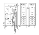
ここで、異なる図の全体を通して同じ参照番号が、同じ又は同様な構成要素を指す図を参照する。図1は、コンピュータ室のための冷却液分配ユニット100の1つの実施形態を示す。冷却液分配ユニットは、従来は、ここでは2つの電子機器フレーム全体とみなされるものより多くの場所を占める、相対的に大きいユニットである。冷却ユニット100内には、電源/制御要素112と、リザーバ/拡張タンク113と、熱交換器114と、ポンプ115(重複する第2ポンプを伴うことが多い)と、設備水(或いは、サイト又はカスタマー用水又は冷却液)注入口116及び排出口117の供給パイプと、結合部120及び配管122により電子機器ラック130に水を向かわせる供給マニホルド118と、配管123及び結合部121により電子機器ラック130から水を向かわせる戻りマニホルド119と、がある。各々の電子機器ラックは、多数の電子機器ドロワ(電子機器サブシステム)135を含む。
Reference is now made to the drawings wherein like reference numerals refer to the same or similar components throughout the different views. FIG. 1 shows one embodiment of a
図2は、図1の冷却システムの動作を概略的に示しており、液体冷却された冷却板155が、電子機器ラック130内の電子機器ドロワー135の電子機器モジュール150に結合された状態で示される。熱は、冷却液分配ユニット100の熱交換器114、配管122、123及び冷却板155で定められるシステム冷却液ループ内で、冷却板155を通してポンプ115により送出されるシステム冷却液により電子機器モジュール150から除去される。システム冷却液ループ及び冷却液分配ユニットは、制御された温度及び圧力、並びに、制御された化学的性質及び清浄度の冷却液を電子機器に供給するように設計される。さらに、システム冷却液は、熱が最終的に伝達される配管116、117内のあまり制御されていない設備冷却液とは物理的に分離されている。図2で示されるシステムにおいては、システム冷却液ループは、残留粒子状物質がループを通って自由に流れるのに十分な大きさの流量のための代表長さを有するため、フィルタ処理は必要とされてこなかった。例えば、直径1.65mmのチャネルをもつ冷却板が、ニューヨーク州アーモンク所在のインターナショナル・ビジネス・マシーンズ・コーポレーションにより販売されるES/9000システムに用いられた。
FIG. 2 schematically illustrates the operation of the cooling system of FIG. 1 with a liquid cooled
上述のとおり、設計者がコンピュータの性能を向上させ続けようとするにつれて、プロセッサの電力レベルは上昇し続ける。電子機器モジュールの電力レベルは、従来の空気冷却技術、さらに従来の液体冷却の冷却板の概念もはるかに越えると予測される。こうした将来の冷却の必要性に対処するために、微小冷却構造体が開発されている。こうした構造体の2つの例は、ニューハンプシャー州クレアモント所在のMikros Manufacturing社、及び独国ベルリン所在のATOTECH社により市販されている。微小冷却構造体の他の例もまた、当技術分野で入手可能である。こうした微小冷却構造体は、これまで用いられた冷却板より小さいオーダーの大きさを上回る代表長さを有する。さらに、微小規模の構造体は、図1及び図2に示されたような冷却システムのシステム冷却液を通って規則的に循環する粒子のオーダーか又はそれより小さい最小寸法を有する。入手可能な微小規模の構造体において、特有の寸法は、現在では50マイクロメートル(ミクロン)から100マイクロメートルまでの範囲であり、技術が成熟するに伴いさらに減少させることができる。こうした小さな幅のスケールにおいては、液体が清浄であることが必須である。こうした寸法において、微小冷却構造体は、放熱板ではなくフィルタに近い働きをし、それにより冷却を阻害する場合がある。 As described above, the power level of the processor continues to increase as the designer continues to improve the performance of the computer. The power level of the electronics module is expected to go well beyond the conventional air cooling technology and even the conventional liquid cooling cold plate concept. Micro-cooling structures have been developed to address these future cooling needs. Two examples of such structures are commercially available from Mikros Manufacturing, Claremont, NH and ATOTECH, Berlin, Germany. Other examples of microcooling structures are also available in the art. Such a microcooling structure has a representative length that exceeds a size on the order of smaller than the cooling plates used so far. In addition, the microscale structure has a minimum dimension on the order of or smaller than particles that circulate regularly through the system coolant of the cooling system as shown in FIGS. In the available microscale structures, the unique dimensions currently range from 50 micrometers to 100 micrometers and can be further reduced as the technology matures. In such a small scale, it is essential that the liquid is clean. In such dimensions, the microcooling structure may act like a filter rather than a heat sink, thereby inhibiting cooling.
この問題に対する1つの解決法は、図1及び図2の冷却アセンブリのシステム冷却液側にフィルタを導入することであろう。これは、残念ながら、付加的な圧力降下を増し、継続的な保守管理を要するため、望ましくない。従って、1つの態様においては、本発明の目的は、システム冷却液ループと熱的に接触し、上述の微小冷却構造体の微小規模の態様に対応するように設計され製造される、電子機器サブシステムと関連付けられた、分離したサブアセンブリを作成することである。 One solution to this problem would be to introduce a filter on the system coolant side of the cooling assembly of FIGS. This is undesirably undesirably increasing the additional pressure drop and requiring ongoing maintenance. Accordingly, in one aspect, an object of the present invention is to provide an electronics sub-system that is designed and manufactured to be in thermal contact with the system coolant loop and to accommodate the micro-scale aspects of the micro-cooling structure described above. Creating separate subassemblies associated with the system.
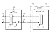
図3は、この目的を達成する冷却システムの1つの実施形態を示す。この冷却システム又は装置は、冷却液分配ユニット100と、1つ又は複数の放熱ユニット195と、を含む。各々の放熱ユニット195は、コンピューティング環境の電子機器ラック130のそれぞれの電子機器サブシステム又はドロワー135と関連付けられる。冷却液分配ユニット100は、ここでも、第1熱交換器114と、第1冷却ループ116、117と、1つ又は複数の第2冷却ループ122、123と、を含む。第1冷却ループ116、117は、設備冷却液を受け取り、少なくともその一部を第1熱交換器114を通して通過させるる。各々の第2冷却ループは、システム冷却液を少なくとも1つの電子機器ドロワー(電子機器サブシステム)135に供給し、かつ、第1熱交換器114において電子機器サブシステム135からの熱を第1冷却ループ116、117の設備冷却液に放出する。システム冷却液は、ポンプ115により、第2冷却ループ122、123内で循環する。
FIG. 3 shows one embodiment of a cooling system that accomplishes this goal. The cooling system or apparatus includes a
各々の放熱ユニット195は、それぞれの電子機器サブシステム135と関連付けられており、第2熱交換器160と、1つ又は複数の第2冷却ループのうちの第2冷却ループ122、123と、第3冷却ループ170と、微小冷却構造体180と、を含む。第2冷却ループ122、123は、システム冷却液を第2熱交換器160に供給し、第3冷却ループ170は、少なくとも1つの電子機器サブシステム135内で、微小冷却構造体180を通して調整冷却液を循環させ、かつ、第2熱交換器160において電子機器サブシステム135の熱発生コンポーネント190(例えば電子機器モジュール)からの熱を放出する。熱は、熱交換器160において第2冷却ループ122、123のシステム冷却液に放出される。調整冷却液は、ポンプ175により、放熱ユニット195の第3冷却ループ170を通って循環する。好適なポンプ175の1つの例は、最初に組み込まれおり、本発明の譲受人に譲渡された、同時出願の「Cooling Apparatus For An Electronics Subsystem Employing A Coolant Flow Drive Apparatus Between Coolant Flow Paths」という発明の名称の特許文献1において提供される。1つの例においては、第3冷却ループ170は閉ループ流路であり、それにより、調整冷却液が以下に説明されるようにフィルタ処理されたときに、粒子が冷却ループに入る機会を最小限にする。
Each
第3冷却ループ170は、冷却アセンブリのシステム冷却液から物理的に分離されていることが有利である。第3冷却ループ170は、電子機器サブシステム135、より具体的には、冷却される電子機器モジュール等の1つ又は複数の熱発生コンポーネントに配置される、別個の専用ループ又はサブアセンブリである。第3冷却ループ170及びそれに関連付けられたコンポーネントは、粒子と材料の両方の適合性(即ち腐食)の観点から清浄な環境を生成するように製造されたサブアセンブリを含む。冷却サブアセンブリ195は、一旦作動すると閉システム(即ち、現場では開かれないシステム)になるように設計される。現場においては閉サブシステムであるので、粒子汚染は、組み立ての際に管理することができる。
The
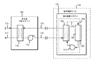
図4及び図6は、例えば放熱ユニットの製造の際に、ユニット内の調整冷却液をフィルタ処理するための代替的なアセンブリを示す。図4では、図3のシステムのサブアセンブリ195が、微小冷却構造体180と一体化するか又は結合することができる電子機器モジュール190と関連付けられて示される。サブアセンブリは、本例では、冷却液が、微小冷却構造体180を通ってではなく、フィルタ210を通って流れることができるように開かれる2つの三方弁200を含む。熱交換器160、第3冷却ループ170、及び三方弁200を介するフィルタ210を通して送出された調整冷却液は、特定の用途に望ましいレベルまで浄化される。フィルタ210は、第3冷却ループ170を通って流れる調整冷却液を所望の方法で浄化するように設計された任意のフィルタ処理機構とすることができ、(例えば、製造及び組み立てプロセスにより発生する)粒子のフィルタ処理と、(例えば、望ましくない腐食性の成分を冷却液から除去するための)化学的フィルタ処理とを含むことができることに注目されたい。フィルタ処理されると、弁200は、第3冷却ループ170からフィルタ210を除去するように手動で又は自動で調節され、これによって、調整冷却液が、ポンプ175によって微小冷却構造体180及び熱交換器160を通って流れることが可能になる(図5を参照されたい)。
4 and 6 show an alternative assembly for filtering the conditioned coolant in the unit, for example during manufacture of the heat dissipation unit. In FIG. 4, the
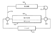
図6は、図3の冷却サブアセンブリ195のループ170内の調整冷却液をフィルタ処理するための代替的な方法を示す。本実施形態においては、接続/遮断結合部220が、フィルタ210を第3冷却ループ170に接続するために用いられる。フィルタ210は、ここでも、例えば、第3冷却ループ170を通って流れる調整冷却液から、望ましくない粒子及び化学成分を除去するための任意のフィルタ処理機構を含むことができる。冷却液は、望ましい冷却液の清浄レベルを実現するのに十分な時間だけ、熱交換器160、第3冷却ループ170及びフィルタ210を通して送出される。
FIG. 6 illustrates an alternative method for filtering the conditioned coolant in the
図7に示されるように、調整冷却液が適切にフィルタ処理された後で、フィルタ210が除去され、再び結合部220を用いて微小冷却構造体180が第3冷却ループ170に挿入される。示される実施形態においては、電子機器モジュール190は、微小冷却構造体180と一体化されるか又はこれに結合されると仮定される。構造体180を電子機器モジュールに結合するための種々の実施形態が、図8乃至図10に示され、以下でさらに説明される。
As shown in FIG. 7, after the adjusted cooling liquid has been appropriately filtered, the
当業者であれば、ここでは、3つの別個の冷却ループを用いる冷却アセンブリが提供されることに気付くであろう。第1冷却ループ及び第2冷却ループは、第2冷却ループ内のシステム冷却液から第1冷却ループ内の設備冷却液に熱を伝達することを可能にする流体間熱交換器を含む冷却液分配ユニットと関連付けられる。1つ又は複数の放熱ユニット又は冷却サブアセンブリが、例えば電子機器ラックの1つ又は複数の電子機器サブシステムと関連付けられる。各々の放熱ユニットは、それぞれの第2冷却ループと、1つの例では、分離した閉ループ流路から成る第3冷却ループと、を含む。放熱ユニットは、さらに、冷却液分配ユニットへの伝達のために、第3冷却ループ内の調整冷却液から第2冷却ループ内のシステム冷却液に熱を放出することを可能にする第2の流体間熱交換器を含む。調整冷却液、システム冷却液及び設備冷却液を分けることにより、各々の冷却ループは、異なる特性又は特徴の冷却液を有することができるという利点がある。これらの異なる特徴は、以下のような異なる冷却液の清浄度、冷却液の圧力、冷却液の相変化、冷却液の流量、冷却液の化学的性質を含むことができる。
・冷却液の清浄度−第3冷却ループ内ではより清浄度の高い冷却液(浄化水など)、システム冷却液ループ内では清浄度の低い冷却液、及び、設備冷却液ループ内ではさらに清浄度の低い冷却液の使用を可能にする。清浄度の高い冷却液(浄化水など)は、放熱ユニットの第3冷却ループにおいて、特に、例えば、汚染物質が微小冷却構造体の動作を妨げるのを防ぐために、小規模の冷却構造体(即ち、チャネル、ノズル、オリフィス、フィン等)と併せて用いられるときに望ましい。
・冷却液の圧力−例えば、第3冷却ループ内の調整冷却液が大気圧より低い圧力であり、第2冷却ループ及び第1冷却ループのシステム冷却液及び設備冷却液が大気圧のままであるか又はそれより高いことを可能にする。これは、例えば、調整冷却液がシステム冷却液とは異なる沸点を有することを可能にする。
・冷却液の相変化−第3冷却ループは、調整冷却液を二相の冷却手法で用いる一方で、システム冷却液及び設備冷却液を一相の冷却液として維持することを可能にする。
・冷却液の流量−冷却システムにおける種々の冷却液の異なる圧力及び相変化温度に関連させることができる。さらに、例えば、システム冷却液を含む第2冷却ループを通る流量より低い、微小冷却構造体を通る流量を用いることが望ましい場合がある。
・冷却液の化学的性質−異なる化学的性質の冷却液流体を、冷却システムの種々の冷却ループに用いることを可能にする。例えば、清浄度のみが異なる設備冷却液及びシステム冷却液の両方として、第1及び第2冷却ループに水を用いることができ、第3冷却ループは、調整冷却液として誘電体を用いることができる。このことは、例えば、冷却されている電子機器サブシステムの1つ又は複数の集積回路チップに調整冷却液が直接接触する実施形態において有利とすることができる。
One skilled in the art will recognize that a cooling assembly is provided here that uses three separate cooling loops. The first cooling loop and the second cooling loop include a coolant-to-fluid heat exchanger that allows heat to be transferred from the system coolant in the second cooling loop to the facility coolant in the first cooling loop. Associated with unit. One or more heat dissipation units or cooling subassemblies are associated with one or more electronic subsystems of, for example, an electronic equipment rack. Each heat dissipation unit includes a respective second cooling loop and, in one example, a third cooling loop consisting of separate closed loop flow paths. The heat dissipating unit further allows a second fluid that allows heat to be released from the conditioned coolant in the third cooling loop to the system coolant in the second cooling loop for transmission to the coolant distribution unit. Includes heat exchanger. By separating the conditioning coolant, the system coolant, and the equipment coolant, there is an advantage that each cooling loop can have a coolant of different characteristics or characteristics. These different features may include different coolant cleanliness, coolant pressure, coolant phase change, coolant flow rate, coolant chemistry, such as:
• Coolant cleanliness-Cooler with higher cleanliness (purified water, etc.) in the third cooling loop, Coolant with lower cleanliness within the system coolant loop, and further cleanliness within the equipment coolant loop Allows the use of low coolant. A highly clean coolant (such as purified water) is used in the third cooling loop of the heat dissipation unit, particularly in order to prevent contaminants from interfering with the operation of the microcooling structure (i.e. small-scale cooling structures (i.e. , Channels, nozzles, orifices, fins, etc.).
Coolant pressure—for example, the regulated coolant in the third cooling loop is at a pressure below atmospheric pressure, and the system and equipment coolants in the second and first cooling loops remain at atmospheric pressure. Or higher. This allows, for example, the regulated coolant to have a different boiling point than the system coolant.
Coolant phase change-The third cooling loop allows the system and equipment coolants to be maintained as a single phase coolant while using the regulated coolant in a two phase cooling approach.
Coolant flow rate-can be related to different pressures and phase change temperatures of various coolants in the cooling system. Further, it may be desirable to use a flow rate through the microcooling structure that is lower than, for example, a flow rate through the second cooling loop that contains the system coolant.
Coolant chemistry-allows coolant fluids of different chemistry to be used in various cooling loops of the cooling system. For example, water can be used for the first and second cooling loops, both as equipment and system coolants that differ only in cleanliness, and the third cooling loop can use a dielectric as the conditioning coolant. . This can be advantageous, for example, in embodiments where the conditioning coolant is in direct contact with one or more integrated circuit chips of the electronics subsystem being cooled.
上述したように、図8乃至図10は、微小冷却構造体180を、電子機器サブシステムの1つ又は複数の熱発生コンポーネントに結合するための種々の実施形態を示す。図8では、電子機器モジュール190は、多数の集積回路チップ192が配置された基板191を含む。モジュール・リッド193は、集積回路チップをモジュール190内に収める。モジュール190は、微小冷却構造体180に機械的に結合された状態で示され、これを通って、調整冷却液(図示せず)が注入口181及び排出口184を介して流れる。モジュール・リッド193及び微小冷却構造体180は、集積回路チップ192から微小規模の構造体を通って流れる調整冷却液への熱伝達を容易にするのに適切な材料で製造される。1つの強化点として、微小冷却構造体180は、現場で交換可能なユニットである放熱ユニットの一部とすることができる。このような場合には、接続/遮断結合部を第2冷却ループに用いて、微小冷却構造体180を通って流れる調整冷却液を含む第3冷却ループを開く必要なく、システム冷却液を新たに交換された放熱ユニットに結合することができる。
As discussed above, FIGS. 8-10 illustrate various embodiments for coupling the
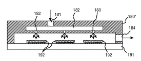
図9は、ここでは準直接式冷却液浸漬と呼ばれる、チップ・アセンブリに結合された微小冷却構造体の代替的な実施形態を示す。本実施形態においては、冷却構造体180’は、上に多数の集積回路チップ192を有する基板191に結合される。多層の熱伝導性流体障壁194が集積回路チップの上に存在し、微小冷却構造体180’を通って流れる調整冷却液からチップを保護する。調整冷却液は、注入口181を介して調整冷却液を受け取る供給マニホルド182と流体連通する微小オリフィス183を介して熱伝導性流体障壁194の上に流れる。調整冷却液は、微小冷却構造体180’における排出口184を介して一体化されたアセンブリから流れる。本実施形態には、どのような種類の冷却液も用いることができ、一例として水が挙げられる。液体は集積回路チップとほぼ直接に接触しているが、集積回路チップとは分離されたままであるという利点がある。準直接式集積冷却構造体及びモジュール・アセンブリの例は、本発明の譲受人に譲渡された、発明の名称を「Electronic Device Substrate Assembly With Impermeable Barrier And Method Of Making」とする特許文献2及び発明の名称を「Electronic Device Substrate Assembly With Multilayer Impermeable Barrier And Method Of Making」とする特許文献3においてより詳細に説明されている。
FIG. 9 shows an alternative embodiment of a microcooling structure coupled to the chip assembly, referred to herein as quasi-direct coolant immersion. In this embodiment, the
図10は、微小冷却構造体を集積回路アセンブリと一体化するためのさらに別の付加的な実施形態を示す。本実施形態は、調整冷却液が、基板191上に配置された多数の集積回路チップ192の上に直接当たるため、直接冷却液浸漬と呼ばれる。図示されるように、微小冷却構造体180’は、ここでも、それぞれの放熱ユニットの第3冷却ループ170に結合された注入口181と流体連通する供給マニホルド182から調整冷却液を供給する微小規模のオリフィス183を含む。図10の微小冷却構造体180’は、例えば図3の放熱ユニット195の第3冷却ループ170と流体連通する排出口184を含む。直接冷却液浸漬においては、基板及び冷却アセンブリは一体的なユニットであり、調整冷却液と集積回路チップとの間に流体障壁は存在しない。このことは、集積回路チップに損傷を与えないように選択された誘電性流体を用いることにより可能である。一体的な微小冷却構造体及び回路サブアセンブリのより詳細な説明は、最初に組み込まれており、本発明の譲受人に譲渡された同時出願の「Cooling Apparatus And Method For An Electronics Module Employing An Integrated Heat Exchange Assembly」という発明の名称の特許文献4において提供される。
FIG. 10 illustrates yet another additional embodiment for integrating the microcooling structure with the integrated circuit assembly. This embodiment is called direct cooling liquid immersion because the adjusted cooling liquid directly hits a large number of
好ましい実施形態がここで詳細に示され説明されてきたが、種々の変更、付加、置換及び同様なものを、本発明の精神から逸脱することなく行うことができること、及び、従ってこれらが添付の特許請求の範囲に定義される本発明の範囲内であると考えられることが当業者には明白であろう。 While the preferred embodiment has been shown and described in detail herein, various changes, additions, substitutions and the like can be made without departing from the spirit of the invention, and thus they are attached. It will be apparent to those skilled in the art that they are considered to be within the scope of the invention as defined in the claims.
Claims (10)
第1熱交換器と、第1冷却ループと、少なくとも1つの第2冷却ループとを含む冷却液分配ユニットであって、前記第1冷却ループは設備冷却液を受け取って前記第1熱交換器を通し、前記少なくとも1つの第2冷却ループは、システム冷却液を少なくとも1つの電子ドロワー・サブシステムに供給し、かつ、前記第1熱交換器において前記少なくとも1つの電子ドロワー・サブサブシステムからの熱を前記第1冷却ループの前記設備冷却液に放出する、冷却液分配ユニットと、
第2熱交換器と、前記少なくとも1つの第2冷却ループと、第3冷却ループとを各々が含む、前記少なくとも1つの電子ドロワー・サブシステムと関連付けられた少なくとも1つの放熱ユニットであって、前記第2冷却ループは前記システム冷却液を前記第2熱交換器に供給し、前記第3冷却ループは、前記少なくとも1つの電子ドロワー・サブシステム内で調整冷却液を循環させ、かつ、前記第2熱交換器において前記少なくとも1つの電子ドロワー・サブシステムからの熱を前記第2冷却ループの前記システム冷却液に放出する、少なくとも1つの放熱ユニットと、
を含み、
前記放熱ユニットの各々の前記第3冷却ループは、前記少なくとも1つの電子ドロワー・サブシステム内に配置された、分離された閉ループ流路を含む、
冷却システム電子ラック。A cooling system electronic rack of at least one electronic drawer subsystem, comprising:
A first heat exchanger, a first cooling loop, a coolant distribution unit and at least one second cooling loop, the first cooling loop the first heat exchanger I received an equipment cooling liquid was passed through the at least one second cooling loop, supplies system coolant to at least one electronic drawer subsystem, and heat from the at least one electronic drawer subsystem subsystem in the first heat exchanger A coolant distribution unit that discharges to the facility coolant of the first cooling loop;
At least one heat dissipation unit associated with the at least one electronic drawer subsystem, each including a second heat exchanger, the at least one second cooling loop, and a third cooling loop, The second cooling loop supplies the system coolant to the second heat exchanger, the third cooling loop circulates a regulated coolant in the at least one electronic drawer subsystem, and the second At least one heat dissipating unit for releasing heat from the at least one electronic drawer subsystem to the system coolant in the second cooling loop in a heat exchanger;
Including
The third cooling loop of each of the heat dissipation units includes a separate closed loop flow path disposed in the at least one electronic drawer subsystem.
Cooling system electronic rack.
第1熱交換器と、第1冷却ループと、少なくとも1つの第2冷却ループとを含む冷却液分配ユニットであって、前記第1冷却ループは設備冷却液を受け取って前記第1熱交換器を通し、前記少なくとも1つの第2冷却ループは、システム冷却液を少なくとも1つの電子ドロワー・サブシステムに供給し、かつ、前記第1熱交換器において前記少なくとも1つの電子ドロワー・サブシステムからの熱を前記第1冷却ループの前記設備冷却液に放出する、冷却液分配ユニットを提供するステップと、
第2熱交換器と、前記少なくとも1つの第2冷却ループと、第3冷却ループとを各々が含む、前記少なくとも1つの電子ドロワー・サブシステムと関連付けられた少なくとも1つの放熱ユニットであって、前記第2冷却ループは前記システム冷却液を前記第2熱交換器に供給し、前記第3冷却ループは、前記少なくとも1つの電子ドロワー・サブシステム内で調整冷却液を循環させ、かつ、前記第2熱交換器において前記少なくとも1つの電子ドロワー・サブシステムからの熱を前記第2冷却ループの前記システム冷却液に放出する、少なくとも1つの放熱ユニットを提供するステップと、
を含み、
前記放熱ユニットの各々の前記第3冷却ループは、前記少なくとも1つの電子ドロワー・サブシステム内に配置された、分離された閉ループ流路を含む、
冷却方法。A method for cooling at least one electronic drawer subsystem comprising:
A coolant distribution unit including a first heat exchanger, a first cooling loop, and at least one second cooling loop, wherein the first cooling loop receives equipment coolant and directs the first heat exchanger. And wherein the at least one second cooling loop supplies system coolant to the at least one electronic drawer subsystem and heat from the at least one electronic drawer subsystem in the first heat exchanger. Providing a coolant distribution unit for discharging to the facility coolant of the first cooling loop;
At least one heat dissipation unit associated with the at least one electronic drawer subsystem, each including a second heat exchanger, the at least one second cooling loop, and a third cooling loop, The second cooling loop supplies the system coolant to the second heat exchanger, the third cooling loop circulates a regulated coolant in the at least one electronic drawer subsystem, and the second Providing at least one heat dissipating unit for releasing heat from the at least one electronic drawer subsystem to the system coolant in the second cooling loop in a heat exchanger;
Including
The third cooling loop of each of the heat dissipation units includes a separate closed loop flow path disposed in the at least one electronic drawer subsystem.
Cooling method.
Applications Claiming Priority (2)
| Application Number | Priority Date | Filing Date | Title |
|---|---|---|---|
| US11/008,711 US6973801B1 (en) | 2004-12-09 | 2004-12-09 | Cooling system and method employing a closed loop coolant path and micro-scaled cooling structure within an electronics subsystem of an electronics rack |
| PCT/EP2005/056581 WO2006061404A1 (en) | 2004-12-09 | 2005-12-07 | Cooling system and method |
Publications (3)
| Publication Number | Publication Date |
|---|---|
| JP2008523599A JP2008523599A (en) | 2008-07-03 |
| JP2008523599A5 JP2008523599A5 (en) | 2008-10-23 |
| JP4511601B2 true JP4511601B2 (en) | 2010-07-28 |
Family
ID=35452409
Family Applications (1)
| Application Number | Title | Priority Date | Filing Date |
|---|---|---|---|
| JP2007544912A Active JP4511601B2 (en) | 2004-12-09 | 2005-12-07 | Cooling system and method |
Country Status (7)
| Country | Link |
|---|---|
| US (1) | US6973801B1 (en) |
| EP (1) | EP1829441B1 (en) |
| JP (1) | JP4511601B2 (en) |
| CN (1) | CN100556260C (en) |
| AT (1) | ATE391406T1 (en) |
| DE (1) | DE602005005859T2 (en) |
| WO (1) | WO2006061404A1 (en) |
Families Citing this family (105)
| Publication number | Priority date | Publication date | Assignee | Title |
|---|---|---|---|---|
| US8464781B2 (en) | 2002-11-01 | 2013-06-18 | Cooligy Inc. | Cooling systems incorporating heat exchangers and thermoelectric layers |
| US7836597B2 (en) | 2002-11-01 | 2010-11-23 | Cooligy Inc. | Method of fabricating high surface to volume ratio structures and their integration in microheat exchangers for liquid cooling system |
| US7508672B2 (en) * | 2003-09-10 | 2009-03-24 | Qnx Cooling Systems Inc. | Cooling system |
| US20070051126A1 (en) * | 2004-11-29 | 2007-03-08 | Seiichi Okuda | Air refrigerant type freezing and heating apparatus |
| US8424885B2 (en) | 2005-12-22 | 2013-04-23 | Elliptical Mobile Solutions, LLC | Method and apparatus for an environmentally-protected electronic equipment enclosure |
| US7578337B2 (en) * | 2005-04-14 | 2009-08-25 | United States Thermoelectric Consortium | Heat dissipating device |
| US7298617B2 (en) * | 2005-10-25 | 2007-11-20 | International Business Machines Corporation | Cooling apparatus and method employing discrete cold plates disposed between a module enclosure and electronics components to be cooled |
| US7298618B2 (en) * | 2005-10-25 | 2007-11-20 | International Business Machines Corporation | Cooling apparatuses and methods employing discrete cold plates compliantly coupled between a common manifold and electronics components of an assembly to be cooled |
| US7992625B1 (en) | 2006-08-18 | 2011-08-09 | United States Thermoelectric Consortium | Fluid-operated heat transfer device |
| US7814965B1 (en) | 2005-10-27 | 2010-10-19 | United States Thermoelectric Consortium | Airflow heat dissipation device |
| US8672732B2 (en) | 2006-01-19 | 2014-03-18 | Schneider Electric It Corporation | Cooling system and method |
| US7365973B2 (en) | 2006-01-19 | 2008-04-29 | American Power Conversion Corporation | Cooling system and method |
| WO2007120530A2 (en) * | 2006-03-30 | 2007-10-25 | Cooligy, Inc. | Integrated liquid to air conduction module |
| EP2032907B1 (en) * | 2006-06-01 | 2018-05-16 | Google LLC | Warm cooling for electronics |
| US8322155B2 (en) | 2006-08-15 | 2012-12-04 | American Power Conversion Corporation | Method and apparatus for cooling |
| US8327656B2 (en) | 2006-08-15 | 2012-12-11 | American Power Conversion Corporation | Method and apparatus for cooling |
| US9568206B2 (en) | 2006-08-15 | 2017-02-14 | Schneider Electric It Corporation | Method and apparatus for cooling |
| US20080043442A1 (en) * | 2006-08-16 | 2008-02-21 | Strickland Travis C | Computer system with thermal conduction |
| US7665325B2 (en) * | 2006-09-12 | 2010-02-23 | International Business Machines Corporation | Multi-fluid cooling system and method with freeze protection for cooling an electronic device |
| US7681404B2 (en) | 2006-12-18 | 2010-03-23 | American Power Conversion Corporation | Modular ice storage for uninterruptible chilled water |
| US8425287B2 (en) | 2007-01-23 | 2013-04-23 | Schneider Electric It Corporation | In-row air containment and cooling system and method |
| US8141620B1 (en) | 2007-02-26 | 2012-03-27 | United States Thermoelectric Consortium (USTC) | Method for conditioning a cooling loop of a heat exchange system |
| US7511959B2 (en) * | 2007-04-25 | 2009-03-31 | Hewlett-Packard Development Company, L.P. | Scalable computing apparatus |
| US7477514B2 (en) * | 2007-05-04 | 2009-01-13 | International Business Machines Corporation | Method of facilitating cooling of electronics racks of a data center employing multiple cooling stations |
| DK2147585T3 (en) | 2007-05-15 | 2017-01-16 | Schneider Electric It Corp | PROCEDURE AND SYSTEM FOR HANDLING EQUIPMENT AND COOLING |
| US7602609B2 (en) * | 2007-05-31 | 2009-10-13 | Liebert Corporation | Cooling system and method of use |
| TW200924625A (en) * | 2007-08-07 | 2009-06-01 | Cooligy Inc | Deformable duct guides that accommodate electronic connection lines |
| US9496200B2 (en) | 2011-07-27 | 2016-11-15 | Coolit Systems, Inc. | Modular heat-transfer systems |
| US9943014B2 (en) | 2013-03-15 | 2018-04-10 | Coolit Systems, Inc. | Manifolded heat exchangers and related systems |
| US20090229283A1 (en) * | 2007-08-24 | 2009-09-17 | Joseph Marsala | Method and apparatus for isothermal cooling of hard disk drive arrays using a pumped refrigerant loop |
| US7963119B2 (en) * | 2007-11-26 | 2011-06-21 | International Business Machines Corporation | Hybrid air and liquid coolant conditioning unit for facilitating cooling of one or more electronics racks of a data center |
| US8553416B1 (en) * | 2007-12-21 | 2013-10-08 | Exaflop Llc | Electronic device cooling system with storage |
| CA2882794C (en) * | 2008-02-15 | 2017-08-22 | The Pnc Financial Services Group, Inc. | Systems and methods for computer equipment management |
| US20090225514A1 (en) | 2008-03-10 | 2009-09-10 | Adrian Correa | Device and methodology for the removal of heat from an equipment rack by means of heat exchangers mounted to a door |
| WO2010017327A1 (en) | 2008-08-05 | 2010-02-11 | Cooligy Inc. | A microheat exchanger for laser diode cooling |
| US20100085708A1 (en) * | 2008-10-07 | 2010-04-08 | Liebert Corporation | High-efficiency, fluid-cooled ups converter |
| US7916483B2 (en) | 2008-10-23 | 2011-03-29 | International Business Machines Corporation | Open flow cold plate for liquid cooled electronic packages |
| US7885070B2 (en) * | 2008-10-23 | 2011-02-08 | International Business Machines Corporation | Apparatus and method for immersion-cooling of an electronic system utilizing coolant jet impingement and coolant wash flow |
| US7961475B2 (en) | 2008-10-23 | 2011-06-14 | International Business Machines Corporation | Apparatus and method for facilitating immersion-cooling of an electronic subsystem |
| US7983040B2 (en) | 2008-10-23 | 2011-07-19 | International Business Machines Corporation | Apparatus and method for facilitating pumped immersion-cooling of an electronic subsystem |
| US7944694B2 (en) | 2008-10-23 | 2011-05-17 | International Business Machines Corporation | Liquid cooling apparatus and method for cooling blades of an electronic system chassis |
| US7903404B2 (en) * | 2009-04-29 | 2011-03-08 | Hewlett-Packard Development Company, L.P. | Data centers |
| US8219362B2 (en) | 2009-05-08 | 2012-07-10 | American Power Conversion Corporation | System and method for arranging equipment in a data center |
| US8369090B2 (en) | 2009-05-12 | 2013-02-05 | Iceotope Limited | Cooled electronic system |
| EP3846601A1 (en) * | 2009-05-12 | 2021-07-07 | Iceotope Group Limited | Cooled electronic system |
| US8081461B2 (en) * | 2009-06-25 | 2011-12-20 | International Business Machines Corporation | Cooling apparatus with thermally conductive porous material and jet impingement nozzle(s) extending therein |
| US8490419B2 (en) * | 2009-08-20 | 2013-07-23 | United States Thermoelectric Consortium | Interlocked jets cooling method and apparatus |
| US8522569B2 (en) | 2009-10-27 | 2013-09-03 | Industrial Idea Partners, Inc. | Utilization of data center waste heat for heat driven engine |
| US9038406B2 (en) | 2010-05-26 | 2015-05-26 | International Business Machines Corporation | Dehumidifying cooling apparatus and method for an electronics rack |
| US8189334B2 (en) | 2010-05-26 | 2012-05-29 | International Business Machines Corporation | Dehumidifying and re-humidifying cooling apparatus and method for an electronics rack |
| US7905096B1 (en) * | 2010-05-26 | 2011-03-15 | International Business Machines Corporation | Dehumidifying and re-humidifying air cooling for an electronics rack |
| US8144467B2 (en) | 2010-05-26 | 2012-03-27 | International Business Machines Corporation | Dehumidifying and re-humidifying apparatus and method for an electronics rack |
| US8345423B2 (en) | 2010-06-29 | 2013-01-01 | International Business Machines Corporation | Interleaved, immersion-cooling apparatuses and methods for cooling electronic subsystems |
| US8179677B2 (en) | 2010-06-29 | 2012-05-15 | International Business Machines Corporation | Immersion-cooling apparatus and method for an electronic subsystem of an electronics rack |
| US8184436B2 (en) | 2010-06-29 | 2012-05-22 | International Business Machines Corporation | Liquid-cooled electronics rack with immersion-cooled electronic subsystems |
| US8351206B2 (en) | 2010-06-29 | 2013-01-08 | International Business Machines Corporation | Liquid-cooled electronics rack with immersion-cooled electronic subsystems and vertically-mounted, vapor-condensing unit |
| US8369091B2 (en) | 2010-06-29 | 2013-02-05 | International Business Machines Corporation | Interleaved, immersion-cooling apparatus and method for an electronic subsystem of an electronics rack |
| US8514575B2 (en) | 2010-11-16 | 2013-08-20 | International Business Machines Corporation | Multimodal cooling apparatus for an electronic system |
| US8274790B2 (en) | 2010-11-16 | 2012-09-25 | International Business Machines Corporation | Automatically reconfigurable liquid-cooling apparatus for an electronics rack |
| US8688413B2 (en) | 2010-12-30 | 2014-04-01 | Christopher M. Healey | System and method for sequential placement of cooling resources within data center layouts |
| US10365667B2 (en) | 2011-08-11 | 2019-07-30 | Coolit Systems, Inc. | Flow-path controllers and related systems |
| US8817474B2 (en) | 2011-10-31 | 2014-08-26 | International Business Machines Corporation | Multi-rack assembly with shared cooling unit |
| US8760863B2 (en) | 2011-10-31 | 2014-06-24 | International Business Machines Corporation | Multi-rack assembly with shared cooling apparatus |
| US20130112378A1 (en) * | 2011-11-04 | 2013-05-09 | Dell Products L.P. | System and Method for Cooling Information Handling Resources |
| EP2795489A4 (en) | 2011-12-22 | 2016-06-01 | Schneider Electric It Corp | Analysis of effect of transient events on temperature in a data center |
| WO2013095494A1 (en) | 2011-12-22 | 2013-06-27 | Schneider Electric It Corporation | System and method for prediction of temperature values in an electronics system |
| US9167728B2 (en) * | 2012-07-18 | 2015-10-20 | International Business Machines Corporation | Information technology equipment cooling method |
| US8964384B2 (en) * | 2012-07-27 | 2015-02-24 | Hewlett-Packard Development Company, L.P. | Component cooling |
| US20140048993A1 (en) * | 2012-08-17 | 2014-02-20 | Apple Inc. | Selective placement of coolant to undercut areas |
| US8925333B2 (en) | 2012-09-13 | 2015-01-06 | International Business Machines Corporation | Thermoelectric-enhanced air and liquid cooling of an electronic system |
| US9351431B2 (en) | 2012-10-11 | 2016-05-24 | International Business Machines Corporation | Cooling system with automated seasonal freeze protection |
| TWI531795B (en) | 2013-03-15 | 2016-05-01 | 水冷系統公司 | Sensors, multiplexed communication techniques, and related systems |
| US9648784B2 (en) | 2013-03-15 | 2017-05-09 | Inertech Ip Llc | Systems and assemblies for cooling server racks |
| US9713285B2 (en) | 2013-03-29 | 2017-07-18 | Hewlett Packard Enterprise Development Lp | Electronic apparatus having a cooling apparatus |
| TW201515563A (en) * | 2013-10-08 | 2015-04-16 | Hon Hai Prec Ind Co Ltd | Heat dissipating system |
| EP3158271B1 (en) | 2014-06-20 | 2021-09-22 | Nortek Air Solutions Canada, Inc. | Systems and methods for managing conditions in enclosed space |
| US10168061B2 (en) * | 2014-11-11 | 2019-01-01 | Emerson Network Power S.R.L. | Conditioning system of the free cooling type for environments, method of operation of a said conditioning system, and apparatus for carrying out such method |
| US10638641B2 (en) | 2014-11-14 | 2020-04-28 | Hewlett Packard Enterprise Development Lp | Cooling rack |
| US11092349B2 (en) | 2015-05-15 | 2021-08-17 | Nortek Air Solutions Canada, Inc. | Systems and methods for providing cooling to a heat load |
| US11143430B2 (en) | 2015-05-15 | 2021-10-12 | Nortek Air Solutions Canada, Inc. | Using liquid to air membrane energy exchanger for liquid cooling |
| US11026351B2 (en) * | 2015-09-25 | 2021-06-01 | Intel Corporation | Computing apparatus with closed cooling loop |
| CA3010515C (en) | 2016-01-08 | 2023-03-21 | Nortek Air Solutions Canada, Inc. | Integrated make-up air system in 100% air recirculation system |
| SG10202107907YA (en) | 2016-03-16 | 2021-08-30 | Inertech Ip Llc | System and methods utilizing fluid coolers and chillers to perform in-series heat rejection and trim cooling |
| US10049963B2 (en) * | 2016-04-18 | 2018-08-14 | Rolls-Royce Plc | Power electronics module |
| JP6907592B2 (en) | 2017-02-28 | 2021-07-21 | 富士通株式会社 | Cooling system and electronic equipment system |
| US11452243B2 (en) | 2017-10-12 | 2022-09-20 | Coolit Systems, Inc. | Cooling system, controllers and methods |
| DE202018102582U1 (en) | 2018-01-23 | 2018-05-22 | MEGWARE Computer Vertrieb und Service GmbH | High temperature direct liquid cooled high performance computer system |
| US10681846B2 (en) | 2018-04-19 | 2020-06-09 | Google Llc | Cooling electronic devices in a data center |
| US10645847B2 (en) | 2018-04-20 | 2020-05-05 | Google Llc | Cooling electronic devices in a data center |
| US10966352B2 (en) | 2018-09-24 | 2021-03-30 | Google Llc | Cooling electronic devices in a data center |
| US10548239B1 (en) * | 2018-10-23 | 2020-01-28 | Google Llc | Cooling electronic devices in a data center |
| GB201916771D0 (en) | 2019-11-18 | 2020-01-01 | Iceotope Group Ltd | Heat sink for liquid cooling |
| US10548240B1 (en) | 2019-01-11 | 2020-01-28 | Google Llc | Cooling electronic devices in a data center |
| US11662037B2 (en) | 2019-01-18 | 2023-05-30 | Coolit Systems, Inc. | Fluid flow control valve for fluid flow systems, and methods |
| EP3977832A4 (en) | 2019-04-14 | 2023-07-26 | Jetcool Technologies, Inc. | Direct contact fluid based cooling module |
| US11473860B2 (en) | 2019-04-25 | 2022-10-18 | Coolit Systems, Inc. | Cooling module with leak detector and related systems |
| CA3140764A1 (en) | 2019-06-27 | 2020-12-30 | Hypertechnologie Ciara Inc. | Microgap system for cooling electronics with direct contact |
| US11801733B2 (en) | 2019-09-25 | 2023-10-31 | Baidu Usa Llc | Liquid cooling loop design for high performance processors in harsh vehicle environment |
| US10959352B1 (en) * | 2020-01-03 | 2021-03-23 | Quanta Computer Inc. | Cooling system with floating cold plate with single pipes |
| WO2021229365A1 (en) | 2020-05-11 | 2021-11-18 | Coolit Systems, Inc. | Liquid pumping units, and related systems and methods |
| WO2022060898A1 (en) | 2020-09-15 | 2022-03-24 | Jetcool Technologies Inc. | High temperature electronic device thermal management system |
| US11211538B1 (en) | 2020-12-23 | 2021-12-28 | Joseph L. Pikulski | Thermal management system for electrically-powered devices |
| US11903166B2 (en) * | 2021-02-01 | 2024-02-13 | Microsoft Technology Licensing, Llc | Systems and methods for immersion cooling with subcooled spray |
| US12048118B2 (en) * | 2021-08-13 | 2024-07-23 | Jetcool Technologies Inc. | Flow-through, hot-spot-targeting immersion cooling assembly |
| TW202407925A (en) | 2022-03-04 | 2024-02-16 | 美商捷控技術有限公司 | Actively cooled heat-dissipation lids for computer processors and processor assemblies |
Family Cites Families (22)
| Publication number | Priority date | Publication date | Assignee | Title |
|---|---|---|---|---|
| DE3032590A1 (en) * | 1980-08-27 | 1982-04-01 | Siemens AG, 1000 Berlin und 8000 München | Cooling system for electrical machines - has prim. cooling agent in direct heat exchange contact with evaporator of heat pump |
| JPS62119620A (en) * | 1985-11-20 | 1987-05-30 | Fujitsu Ltd | Constitution system for cooling water supply equipment |
| US5131233A (en) | 1991-03-08 | 1992-07-21 | Cray Computer Corporation | Gas-liquid forced turbulence cooling |
| SE505272C2 (en) * | 1994-12-14 | 1997-07-28 | Ericsson Telefon Ab L M | Cooling system for telecommunications equipment |
| JP2874684B2 (en) * | 1997-03-27 | 1999-03-24 | 日本電気株式会社 | Heat dissipation structure of plug-in unit |
| US5924482A (en) | 1997-10-29 | 1999-07-20 | Motorola, Inc. | Multi-mode, two-phase cooling module |
| US6019165A (en) | 1998-05-18 | 2000-02-01 | Batchelder; John Samuel | Heat exchange apparatus |
| US20020134544A1 (en) * | 2000-09-07 | 2002-09-26 | Thermotek, Inc. | Passive cooling system and method |
| US6408937B1 (en) | 2000-11-15 | 2002-06-25 | Sanjay K. Roy | Active cold plate/heat sink |
| US7225864B2 (en) * | 2001-02-08 | 2007-06-05 | Oriol Inc. | Multi-channel temperature control system for semiconductor processing facilities |
| US6604370B2 (en) | 2001-02-22 | 2003-08-12 | Hewlett-Packard Development Company, L.P. | Variably configured sprayjet cooling system |
| US6498725B2 (en) | 2001-05-01 | 2002-12-24 | Mainstream Engineering Corporation | Method and two-phase spray cooling apparatus |
| US6808371B2 (en) | 2001-09-25 | 2004-10-26 | Matsushita Electric Industrial Co., Ltd. | Ultra-thin pump and cooling system including the pump |
| US6587345B2 (en) | 2001-11-09 | 2003-07-01 | International Business Machines Corporation | Electronic device substrate assembly with impermeable barrier and method of making |
| US6628520B2 (en) * | 2002-02-06 | 2003-09-30 | Hewlett-Packard Development Company, L.P. | Method, apparatus, and system for cooling electronic components |
| US6604571B1 (en) | 2002-04-11 | 2003-08-12 | General Dynamics Land Systems, Inc. | Evaporative cooling of electrical components |
| US6625023B1 (en) | 2002-04-11 | 2003-09-23 | General Dynamics Land Systems, Inc. | Modular spray cooling system for electronic components |
| US6940712B2 (en) | 2002-07-17 | 2005-09-06 | International Business Machines Corporation | Electronic device substrate assembly with multilayer impermeable barrier and method of making |
| US6807056B2 (en) * | 2002-09-24 | 2004-10-19 | Hitachi, Ltd. | Electronic equipment |
| US7146822B2 (en) | 2002-12-30 | 2006-12-12 | Intel Corporation | Centrifugal liquid pump with perimeter magnetic drive |
| CN100338983C (en) * | 2003-12-03 | 2007-09-19 | 国际商业机器公司 | Cooling system and method employing for ensuring cooling of multiple electronics subsystems |
| US7106590B2 (en) * | 2003-12-03 | 2006-09-12 | International Business Machines Corporation | Cooling system and method employing multiple dedicated coolant conditioning units for cooling multiple electronics subsystems |
-
2004
- 2004-12-09 US US11/008,711 patent/US6973801B1/en active Active
-
2005
- 2005-12-07 DE DE602005005859T patent/DE602005005859T2/en active Active
- 2005-12-07 AT AT05817223T patent/ATE391406T1/en not_active IP Right Cessation
- 2005-12-07 JP JP2007544912A patent/JP4511601B2/en active Active
- 2005-12-07 EP EP05817223A patent/EP1829441B1/en active Active
- 2005-12-07 CN CN200580042255.3A patent/CN100556260C/en active Active
- 2005-12-07 WO PCT/EP2005/056581 patent/WO2006061404A1/en active IP Right Grant
Also Published As
| Publication number | Publication date |
|---|---|
| CN101091424A (en) | 2007-12-19 |
| CN100556260C (en) | 2009-10-28 |
| DE602005005859T2 (en) | 2009-05-20 |
| EP1829441A1 (en) | 2007-09-05 |
| JP2008523599A (en) | 2008-07-03 |
| EP1829441B1 (en) | 2008-04-02 |
| WO2006061404A1 (en) | 2006-06-15 |
| DE602005005859D1 (en) | 2008-05-15 |
| ATE391406T1 (en) | 2008-04-15 |
| US6973801B1 (en) | 2005-12-13 |
Similar Documents
| Publication | Publication Date | Title |
|---|---|---|
| JP4511601B2 (en) | Cooling system and method | |
| US7274566B2 (en) | Cooling apparatus for an electronics subsystem employing a coolant flow drive apparatus between coolant flow paths | |
| US7272005B2 (en) | Multi-element heat exchange assemblies and methods of fabrication for a cooling system | |
| US7298618B2 (en) | Cooling apparatuses and methods employing discrete cold plates compliantly coupled between a common manifold and electronics components of an assembly to be cooled | |
| US10070560B2 (en) | Drawer-level immersion-cooling with hinged, liquid-cooled heat sink | |
| US7184269B2 (en) | Cooling apparatus and method for an electronics module employing an integrated heat exchange assembly | |
| US9282678B2 (en) | Field-replaceable bank of immersion-cooled electronic components and separable heat sinks | |
| US9210830B2 (en) | Immersion-cooled and conduction-cooled method for electronic system | |
| US9332674B2 (en) | Field-replaceable bank of immersion-cooled electronic components | |
| JP5671731B2 (en) | Liquid cooling system, electronic equipment rack, and manufacturing method thereof | |
| US9253921B2 (en) | Coolant-conditioning unit with automated control of coolant flow valves | |
| US9357674B2 (en) | Liquid-cooling apparatus with integrated coolant filter | |
| US20060187639A1 (en) | Electronic component cooling and interface system | |
| US20150109730A1 (en) | Direct coolant contact vapor condensing | |
| JP2008523599A5 (en) | ||
| JP2009527897A (en) | Cooling system | |
| JP2009527897A5 (en) | ||
| EP2016357A2 (en) | Methodology of cooling multiple heat sources in a personal computer through the use of multiple fluid-based heat exchanging loops coupled via modular bus-type heat exchangers | |
| WO2008005392A2 (en) | Reservoir for liquid cooling systems used to provide make-up fluid and trap gas bubbles | |
| AU2015339823A1 (en) | Method of absorbing heat with series-connected heat sink modules |
Legal Events
| Date | Code | Title | Description |
|---|---|---|---|
| A521 | Request for written amendment filed |
Free format text: JAPANESE INTERMEDIATE CODE: A523 Effective date: 20080901 |
|
| A621 | Written request for application examination |
Free format text: JAPANESE INTERMEDIATE CODE: A621 Effective date: 20080901 |
|
| A871 | Explanation of circumstances concerning accelerated examination |
Free format text: JAPANESE INTERMEDIATE CODE: A871 Effective date: 20100219 |
|
| A975 | Report on accelerated examination |
Free format text: JAPANESE INTERMEDIATE CODE: A971005 Effective date: 20100305 |
|
| A131 | Notification of reasons for refusal |
Free format text: JAPANESE INTERMEDIATE CODE: A131 Effective date: 20100309 |
|
| A521 | Request for written amendment filed |
Free format text: JAPANESE INTERMEDIATE CODE: A523 Effective date: 20100405 |
|
| TRDD | Decision of grant or rejection written | ||
| A01 | Written decision to grant a patent or to grant a registration (utility model) |
Free format text: JAPANESE INTERMEDIATE CODE: A01 Effective date: 20100427 |
|
| A01 | Written decision to grant a patent or to grant a registration (utility model) |
Free format text: JAPANESE INTERMEDIATE CODE: A01 |
|
| A61 | First payment of annual fees (during grant procedure) |
Free format text: JAPANESE INTERMEDIATE CODE: A61 Effective date: 20100506 |
|
| FPAY | Renewal fee payment (event date is renewal date of database) |
Free format text: PAYMENT UNTIL: 20130514 Year of fee payment: 3 |
|
| R150 | Certificate of patent or registration of utility model |
Ref document number: 4511601 Country of ref document: JP Free format text: JAPANESE INTERMEDIATE CODE: R150 Free format text: JAPANESE INTERMEDIATE CODE: R150 |
|
| FPAY | Renewal fee payment (event date is renewal date of database) |
Free format text: PAYMENT UNTIL: 20140514 Year of fee payment: 4 |
|
| R250 | Receipt of annual fees |
Free format text: JAPANESE INTERMEDIATE CODE: R250 |
|
| S111 | Request for change of ownership or part of ownership |
Free format text: JAPANESE INTERMEDIATE CODE: R313113 |
|
| R350 | Written notification of registration of transfer |
Free format text: JAPANESE INTERMEDIATE CODE: R350 |
|
| R250 | Receipt of annual fees |
Free format text: JAPANESE INTERMEDIATE CODE: R250 |
|
| R250 | Receipt of annual fees |
Free format text: JAPANESE INTERMEDIATE CODE: R250 |
|
| R250 | Receipt of annual fees |
Free format text: JAPANESE INTERMEDIATE CODE: R250 |
|
| R250 | Receipt of annual fees |
Free format text: JAPANESE INTERMEDIATE CODE: R250 |
|
| R250 | Receipt of annual fees |
Free format text: JAPANESE INTERMEDIATE CODE: R250 |
|
| R250 | Receipt of annual fees |
Free format text: JAPANESE INTERMEDIATE CODE: R250 |
|
| R250 | Receipt of annual fees |
Free format text: JAPANESE INTERMEDIATE CODE: R250 |
|
| R250 | Receipt of annual fees |
Free format text: JAPANESE INTERMEDIATE CODE: R250 |
|
| R250 | Receipt of annual fees |
Free format text: JAPANESE INTERMEDIATE CODE: R250 |