JP4510528B2 - Circuit breaker instantaneous trip device - Google Patents
Circuit breaker instantaneous trip device Download PDFInfo
- Publication number
- JP4510528B2 JP4510528B2 JP2004173565A JP2004173565A JP4510528B2 JP 4510528 B2 JP4510528 B2 JP 4510528B2 JP 2004173565 A JP2004173565 A JP 2004173565A JP 2004173565 A JP2004173565 A JP 2004173565A JP 4510528 B2 JP4510528 B2 JP 4510528B2
- Authority
- JP
- Japan
- Prior art keywords
- iron piece
- movable iron
- tripping
- contact
- tripping member
- Prior art date
- Legal status (The legal status is an assumption and is not a legal conclusion. Google has not performed a legal analysis and makes no representation as to the accuracy of the status listed.)
- Active
Links
Images


Description
本件の発明は,引外し機構を備えた回路遮断器における瞬時引外し装置に関するものである。 The present invention relates to an instantaneous trip device in a circuit breaker having a trip mechanism.
従来の瞬時引外し装置には,図5に示したようなものがあった。これは,前面支え部と背面支え部と上側逃げ部と下側逃げ部と上側斜辺部と下側斜辺部と上側突片掛け部と下側突片掛け部とからなる可動鉄片挿入孔を有する電磁枠と,前記可動鉄片挿入孔に係合する第一の突片及び第二の突片を有するとともに第一の突片及び第二の突片と対向し電磁枠と可動鉄片とを組み付けた際に可動鉄片の挿入深さを決める挿入止め片を有し挿入止め片を軸にして回転可動可能な可動鉄片と,可動鉄片の第一の突片及び第二の突片とは反対の他端に設けられたばね掛け穴bと電磁枠に設けられたばね掛け穴a間に懸架に係合され可動鉄片と電磁枠とからなる磁気回路を通常は開の状態に付勢せしめるばねと,前記磁気回路の内側に設けられ磁気回路を磁化する導体とを具備することを特徴として構成されたものである。 A conventional instantaneous tripping device is as shown in FIG. It has a movable iron piece insertion hole composed of a front support part, a back support part, an upper escape part, a lower escape part, an upper oblique part, a lower oblique part, an upper projecting part hanging part, and a lower projecting part attaching part. An electromagnetic frame and a first projecting piece and a second projecting piece that are engaged with the movable iron piece insertion hole, and are opposed to the first projecting piece and the second projecting piece, and the electromagnetic frame and the movable iron piece are assembled. A movable iron piece that has an insertion stop piece that determines the insertion depth of the movable iron piece and can be rotated around the insertion stop piece, and the opposite of the first and second protrusion pieces of the movable iron piece A spring which is engaged with a suspension between a spring hooking hole b provided at the end and a spring hooking hole a provided in the electromagnetic frame, and normally biases the magnetic circuit composed of the movable iron piece and the electromagnetic frame; And a conductor provided inside the circuit for magnetizing the magnetic circuit.
また,図6に示した回路遮断器に用いられている引外し装置があった。これは,バイメタルや電磁素子などで構成され,遮断器が接続された電路に過電流や短絡電流など事故電流が流れた場合,開閉機構部の引外し部材に作用して接点閉を保持する係合を外し接点を閉から開に引き外すものである。 There was also a tripping device used in the circuit breaker shown in FIG. This consists of bimetal, electromagnetic elements, etc., and when an accident current such as overcurrent or short circuit current flows through the circuit connected to the circuit breaker, it acts on the tripping member of the switching mechanism to keep the contact closed. And the contact is pulled from closed to open.
しかしながら,従来の引外し装置においては次のような問題があった。引外し装置は,通常,該引外し装置を構成する可動鉄片と電磁枠とからなり,磁束が貫く断面積をもった磁気回路を形成しており,平常は該磁気回路に磁気抵抗(ギャップ)を設けるように配置されている。短絡電流等が発生した場合には,磁気回路を貫くように配置されている導体に流れる電流によって磁気回路が磁化され,電磁枠は可動鉄片を吸引し,吸引の過程でラッチを形成した引外し部材を引き外すように作用し開閉機構部を動作させるようになっており,可動鉄片は引外し部材に作用するにあたり,十分な作用力(吸引力)を得るように設けられる。 However, the conventional tripping device has the following problems. The tripping device is usually composed of a movable iron piece and an electromagnetic frame constituting the tripping device, and forms a magnetic circuit having a cross-sectional area through which magnetic flux penetrates. Normally, the magnetic circuit has a magnetoresistance (gap). It arrange | positions so that it may provide. When a short-circuit current or the like occurs, the magnetic circuit is magnetized by the current flowing through the conductor arranged so as to penetrate the magnetic circuit, and the electromagnetic frame attracts the movable iron piece and forms a latch that forms a latch in the process of attraction. The opening / closing mechanism is operated by pulling off the member, and the movable iron piece is provided so as to obtain a sufficient action force (suction force) when acting on the tripping member.
即ち,吸引力は導体を流れる電流の大きさ,磁気回路の断面積,及びギャップ等を要因としてその大きさが決まり,可動鉄片の大きさ,可動鉄片をギャップを設ける方向に付勢するばね部材の引っ張り力,引外し部材への作用力に抗して可動鉄片を動作させるように発生させる必要がある。
可動鉄片は,ラッチを形成した引外し部材を引き外すため,その引外しのための移動量を確保する必要がある。このため所定の大きさのギャップを設ける必要があり,ギャップに比例して磁気回路を駆動させるための吸引力は大きくなるため,その吸引力を発生させるためには所定の大きさの断面積を確保する必要があった。
That is, the attractive force is determined by factors such as the current flowing through the conductor, the cross-sectional area of the magnetic circuit, and the gap, and the size of the movable iron piece and the spring member that urges the movable iron piece in the direction in which the gap is provided. It is necessary to generate the movable iron pieces to operate against the pulling force and the acting force on the tripping member.
Since the movable iron piece pulls out the tripping member formed with the latch, it is necessary to secure a moving amount for the tripping. For this reason, it is necessary to provide a gap of a predetermined size, and since the attractive force for driving the magnetic circuit increases in proportion to the gap, a cross-sectional area of a predetermined size is required to generate the attractive force. It was necessary to secure.
また,所定の電流値にて引外し装置を駆動させる場合,駆動に必要な力が一番大きくかかる引き始めに所定の駆動力を得られるように磁気回路を構成する必要があった。可動鉄片と引外し装置との当接は,一箇所で行われるため,その当接箇所にて引外し部材を引き外しできる駆動力が得られるよう磁気回路を構成しておく必要があるが,ギャップの大きさと吸引力は反比例の関係にあるため,引き始めに必要な吸引力に比べて駆動後の可動鉄片に必要な吸引力は小さくてよく,引き始め以後の吸引力は余剰であるような構成であった。このように,引き始めに必要な吸引力が得られるように磁気回路を構成しているため,磁気回路の断面積は大きくなり,即ち引外し装置の大きさが大きくなるため,回路遮断器内に占めるスペースが大きくなり小型化には向かず,また,磁気回路に発生する吸引力を効率的に使用できないという課題があった。 Further, when the tripping device is driven at a predetermined current value, it is necessary to configure the magnetic circuit so that a predetermined driving force can be obtained at the beginning of the pulling when the force required for driving is the largest. Since the contact between the movable iron piece and the tripping device is performed at one place, it is necessary to configure a magnetic circuit so as to obtain a driving force capable of removing the tripping member at the contact place. Since the size of the gap and the suction force are inversely related, the suction force required for the movable iron piece after driving may be smaller than the suction force required for the start of pulling, and the suction force after the start of pulling is excessive. It was a simple configuration. Thus, since the magnetic circuit is configured so as to obtain the attractive force required for the start of pulling, the cross-sectional area of the magnetic circuit is increased, that is, the size of the tripping device is increased. There is a problem that the space occupied by the magnetic circuit becomes large and is not suitable for miniaturization, and the attractive force generated in the magnetic circuit cannot be used efficiently.
本発明は,このような課題を解決するために,引外し装置の小型化を図り,発生する吸引力を効率的に使用することが可能な回路遮断器の引外し装置を提供することを目的とするものである。 In order to solve such a problem, the present invention aims to provide a tripping device for a circuit breaker capable of reducing the size of the tripping device and efficiently using the generated suction force. It is what.
以上のような課題を解決するために,請求項1の発明においては,
過電流を検出し接触子を開極させるよう開閉機構のラッチに作用して引外し動作を行う回路遮断器の瞬時引外し装置を,
前記ラッチ部を構成し一端を回動自在に保持された引外し部材と,
導体近傍に配設され,過電流が発生した際には電磁力により,一端を回動自在に保持された可動鉄片を吸引吸着せしめる可動鉄片吸着部を有する電磁枠とを含んで構成し,
引外し部材及び可動鉄片には,可動鉄片が可動鉄片吸着部に吸着されるよう回動する移動軌跡において,先に互いに当接しあう第一の当接部と,続いて当接しあう第二の当接部とを設け,前記第一の当接部は,第二の当接部と比べて,前記引外し部材においては引外し部材の回転中心から遠い位置に設けられるとともに,前記可動鉄片においては可動鉄片の回転中心から遠い位置に設けられ,引外し装置の動作時において,引外し部材及び可動鉄片における互いに当接しあう第一の当接部が当接し引外し部材が一定量回動し,続いて互いに当接しあう第二の当接部が当接し引外し部材をさらに回動し,引外し部材のラッチに作用して引外しを行うことを特徴として回路遮断器の瞬時引外し装置を提供したものである。
In order to solve the above problems, in the invention of
A circuit breaker instantaneous trip device that operates on the latch of the switching mechanism to detect the overcurrent and open the contact,
A tripping member that constitutes the latch portion and is rotatably held at one end;
An electromagnetic frame having a movable iron piece adsorbing portion that is disposed in the vicinity of the conductor and attracts and adsorbs a movable iron piece that is rotatably held at one end by electromagnetic force when an overcurrent is generated;
The tripping member and the movable iron piece include a first abutting portion that first abuts with each other and a second abutting member that subsequently abuts in the movement trajectory rotating so that the movable iron piece is attracted to the movable iron piece adsorption portion. The first contact portion is provided at a position farther from the center of rotation of the tripping member in the tripping member than the second contact portion, and in the movable iron piece Is provided at a position far from the rotation center of the movable iron piece, and when the tripping device is operated, the tripping member and the first abutting portion of the movable iron piece which are in contact with each other come into contact with each other and the tripping member rotates by a certain amount. . And an instantaneous tripping device for a circuit breaker characterized in that a second abutting portion that abuts each other abuts further, further rotates the tripping member, and acts on a latch of the tripping member to perform tripping Is provided.
これにより,吸引力により可動鉄片が引外し部材に作用を始める際(引き始めの際)には,引外し部材の回動中心から,より離れた箇所(第一の当接部)に当接して作用することにより,引外し部材を回転させるための力がより小さくてよく,即ち,必要な吸引力を小さくでき,駆動後においては,第一の当接部と比べて回動中心に近い箇所(第二の当接部)に当接して作用することにより,磁気回路におけるギャップが小さくなり増加した吸引力を利用して引外し部材に作用するために,発生する吸引力を効率的に使用することが可能である。また,これにより磁気回路の断面積を小さくすることができるため引外し装置を小型化することが可能である。
As a result, when the movable iron piece starts to act on the tripping member due to the suction force (at the start of pulling), it comes into contact with a location (first abutting portion) that is further away from the rotation center of the tripping member. Therefore, the force for rotating the tripping member may be smaller, that is, the necessary suction force can be reduced, and is closer to the center of rotation than the first contact portion after driving. By acting in contact with the location (second contact portion), the gap in the magnetic circuit becomes smaller and acts on the tripping member using the increased attractive force. It is possible to use. In addition, since the cross-sectional area of the magnetic circuit can be reduced thereby, the tripping device can be reduced in size.
本件の発明によれば、引外し装置の小型化を図れ,発生する吸引力を効率的に使用することが可能な回路遮断器の引外し装置を提供することができる。 According to the present invention, it is possible to provide a tripping device for a circuit breaker that can reduce the size of the tripping device and can efficiently use the generated suction force.
以下,本発明の実施の形態について,図面を用いて詳細に説明する。 Hereinafter, embodiments of the present invention will be described in detail with reference to the drawings.
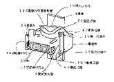
図1は本発明の引外し装置を組み込んだ回路遮断器の内部構造図である。
回路遮断器1は,電源側と負荷側を結ぶ方向を長手方向とした場合に,該長手方向において分割されたカバーa100aとカバーb100bとを対向させるように設けてその外郭,即ち器体が構成される。回路遮断器1を構成する各部品はこれらの分割されたカバーa100aとカバーb100bに挿み込まれるように収納される。
FIG. 1 is an internal structural diagram of a circuit breaker incorporating the trip device of the present invention.
The
101a,101bは,分電盤に設けられる各分岐開閉器に電流を供給する母線や分岐線などから電流を供給される電源側端子である。 Reference numerals 101a and 101b denote power supply side terminals to which current is supplied from a bus or a branch line that supplies current to each branch switch provided in the distribution board.
102a,102bは,負荷側電路に接続され,負荷機器に電流を供給する負荷側端子である。 Reference numerals 102a and 102b denote load-side terminals that are connected to the load-side electric circuit and supply current to the load device.
103は,可動接点を備えた可動接触子1032と,該可動接点と対をなし対向して固定接点を備えた固定接触子1031とからなり電路を開閉する接点装置である。 Reference numeral 103 denotes a contact device that includes a movable contact 1032 having a movable contact and a fixed contact 1031 having a fixed contact that is opposed to the movable contact and opens and closes an electric circuit.
104は,接点装置103を開閉動作する開閉機構部で,遮断器の器体に露望して配置される操作ハンドルにより接点装置を開閉動作させるリンク部材から構成される。 Reference numeral 104 denotes an opening / closing mechanism that opens and closes the contact device 103. The opening / closing mechanism 104 includes a link member that opens and closes the contact device by an operation handle that is disposed on the body of the circuit breaker.
105は,過電流発生時などに開閉機構部104に作用し可動接点を開極させる引き外し機構で,開閉機構部104とのラッチ部1052を形成する引外し部材1051,導体であるバイメタルや,電磁式引き外し装置を含んで構成される。 105 is a tripping mechanism that acts on the opening / closing mechanism 104 to open the movable contact when an overcurrent occurs, and the like. A tripping member 1051 that forms a latch portion 1052 with the opening / closing mechanism 104, a bimetal that is a conductor, It includes an electromagnetic trip device.
回路遮断器1は,電源端子101b側が電源極側で,電源端子101aが中性極側である。電源端子101a,101bはそれぞれ導体を介して接点装置103に接続され,接点装置からは,電源極側においては引き外し機構105を介して,負荷端子102a,102bに導体で接続されている。
In the
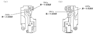
図2は,引外し装置を示した構造図であり,図2(a)は図1の内部構造図に臨む方向とは反対の方向から引外し装置1051を見た図である。図2(b)は図1の内部構造図に臨む方向から引外し装置1051を見た図である。 FIG. 2 is a structural diagram showing the tripping device, and FIG. 2A is a diagram of the tripping device 1051 viewed from the direction opposite to the direction facing the internal structural diagram of FIG. FIG. 2B is a view of the tripping device 1051 viewed from the direction facing the internal structure diagram of FIG.
引外し装置1051は,電磁枠1054と,電磁鉄片1053を弾性的に保持し電磁枠1054に装着される可動鉄片受1056と,ラッチ部を構成し一端を回動自在に保持された引外し部材1051とを含んで構成されている。 The tripping device 1051 includes an electromagnetic frame 1054, a movable iron piece holder 1056 that elastically holds the electromagnetic iron piece 1053 and is attached to the electromagnetic frame 1054, and a tripping member that constitutes a latch portion and is rotatably held at one end. 1051.
電磁枠1054は,電磁鉄片1053と磁気回路を構成するように設けられており,該磁気回路を貫くように導体であるバイメタル1055が配設され,電磁枠1054はバイメタル1055を略包囲するよう形成されている。 The electromagnetic frame 1054 is provided so as to constitute a magnetic circuit with the electromagnetic iron piece 1053, and a bimetal 1055 as a conductor is provided so as to penetrate the magnetic circuit, and the electromagnetic frame 1054 is formed so as to substantially surround the bimetal 1055. Has been.
電磁鉄片1053はかしめ加工により,電磁鉄片受1055に弾性的に保持されており,図2(a)中に示したように,可動鉄片回動軸1054aを中心として回動動作を行い,常に前記磁気回路にギャップを設ける方向,即ち反時計回りの方向に付勢されている。
可動鉄片1053の形状は,該回動中心から直線状に延出したのち,一旦緩く折れ曲がり,再び前記直線状の延出部分と略平行になるように形成され,回動中心から長く延出するように設けられている。
The electromagnetic iron piece 1053 is elastically held by the electromagnetic iron piece holder 1055 by caulking, and as shown in FIG. 2A, the electromagnetic iron piece 1053 rotates around the movable iron piece rotating shaft 1054a, and always The magnetic circuit is biased in a direction in which a gap is provided, that is, in a counterclockwise direction.
The shape of the movable iron piece 1053 is linearly extended from the center of rotation, then once bent gently, again formed so as to be substantially parallel to the linear extension portion, and extended from the center of rotation. It is provided as follows.
引外し部材1051は,可動鉄片1053が電磁枠1054に吸引される際に当接するように,まず,引外し部材回動軸1051aからラッチ部1052を形成した部分が設けられ,略U字型に折れ曲がり,当接部を形成した部分が設けられている。 The tripping member 1051 is provided with a portion where a latch portion 1052 is formed from the tripping member rotation shaft 1051a so that the movable iron piece 1053 contacts when the movable iron piece 1053 is attracted to the electromagnetic frame 1054. A portion that is bent and forms a contact portion is provided.
可動鉄片1053と引外し部材1051には互いに当接しあう当接部が2箇所設けられており,可動鉄片においては,緩く折れ曲がった部分が第一の当接部1053a,回動軸とは反対側の突端部分が第二の当接部1053bであり,引外し部材1051においては,略U字に折れ曲がった部分に設けられた突出部が第一の当接部1051a,回動軸とは反対側の突端部分が第二の当接部1051bである。 The movable iron piece 1053 and the tripping member 1051 are provided with two contact portions that contact each other. In the movable iron piece, the loosely bent portion is the first contact portion 1053a, opposite to the rotating shaft. The projecting end portion is a second abutting portion 1053b, and in the tripping member 1051, the protruding portion provided in the substantially bent portion is a first abutting portion 1051a opposite to the rotating shaft. The protruding end portion is the second contact portion 1051b.
また,過電流発生時にはバイメタルにより引外し部材を駆動できるように,引外し部材1051の略U字に折れ曲がった部分にはバイメタル当接部1051dが設けられている。 Further, a bimetal abutting portion 1051d is provided at a portion of the tripping member 1051 that is bent into a substantially U shape so that the tripping member can be driven by the bimetal when an overcurrent occurs.
次に,短絡電流等による引外し装置105の動作について説明を行う。 Next, the operation of the trip device 105 due to a short-circuit current or the like will be described.
図2において,電磁枠1054と可動鉄片1053に略包囲された導体であるバイメタル1055に電流が流れることにより,電磁枠1054と可動鉄片1053に磁気回路が形成される。バイメタル1055に所定以上の電流が流れた場合,即ち短絡電流等が発生した場合,電磁枠1054と可動鉄片1053には互いに引き合うように吸引力が発生し,該吸引力により可動鉄片1053は可動鉄片回動軸1054aを回動中心として回動し,可動鉄片1053の第一の当接部1053aは引外し部材1051の第一の当接部1051aと当接しあう。図3にその例を示した。図2と同様に図3(a)は図1の内部構造図に臨む方向とは反対の方向から引外し装置1051を見た図であり,図3(b)は図1の内部構造図に臨む方向から引外し装置1051を見た図である。可動鉄片1053は引外し部材回動軸1051cから,より遠い位置で作用するために,軽い作用力で引外し部材1051を駆動(引外し)させることが可能である。 In FIG. 2, when a current flows through a bimetal 1055 that is a conductor substantially surrounded by the electromagnetic frame 1054 and the movable iron piece 1053, a magnetic circuit is formed in the electromagnetic frame 1054 and the movable iron piece 1053. When a current exceeding a predetermined value flows through the bimetal 1055, that is, when a short-circuit current or the like is generated, an attractive force is generated so as to attract the electromagnetic frame 1054 and the movable iron piece 1053, and the movable iron piece 1053 is moved by the attractive force. The first abutting portion 1053a of the movable iron piece 1053 is abutted with the first abutting portion 1051a of the tripping member 1051 by rotating about the rotating shaft 1054a. An example is shown in FIG. 3A is a view of the tripping device 1051 viewed from a direction opposite to the direction facing the internal structure diagram of FIG. 1, and FIG. 3B is a diagram of the internal structure diagram of FIG. It is the figure which looked at the trip apparatus 1051 from the direction which faces. Since the movable iron piece 1053 acts at a position farther from the tripping member rotation shaft 1051c, the tripping member 1051 can be driven (pulled off) with a light acting force.
続いて,図4(図4(a)は図1の内部構造図に臨む方向とは反対の方向から引外し装置1051を見た図である。図4(b)は図1の内部構造図に臨む方向から引外し装置105を見た図である。)に示したように,可動鉄片1053が回動するにつれて,可動鉄片1053と引外し部材1051の当接位置が第一の当接部から第二の当接部に変化する。この段階では,磁気回路におけるギャップが引き始めと比べて小さく,強い吸引力が発生し,さらに,可動鉄片1053において回動中心1054aから第一の当接部1053aまでの長さ(L1)に比べて,第二の当接部1053bまでの長さ(L2)の方が短くなり,可動鉄片1053が引外し部材1051aに作用する力は(L2/L1)倍に増加された状態で引外し部材1051に作用しラッチを引き外す。 4 (FIG. 4A) is a view of the tripping device 1051 viewed from a direction opposite to the direction facing the internal structure diagram of FIG. 1. FIG. 4B is an internal structure diagram of FIG. As shown in FIG. 3, the contact position between the movable iron piece 1053 and the tripping member 1051 is changed to the first contact portion as the movable iron piece 1053 rotates. To the second contact portion. At this stage, the gap in the magnetic circuit is smaller than that at the start of pulling, and a strong attractive force is generated. Further, in the movable iron piece 1053, compared with the length (L1) from the rotation center 1054a to the first contact portion 1053a. Thus, the length (L2) to the second contact portion 1053b is shorter, and the tripping member is in a state where the force acting on the tripping member 1051a by the movable iron piece 1053 is increased (L2 / L1) times. Acts on 1051 to release the latch.
即ち,可動鉄片1053と引外し部材1051との2箇所の当接部において,電磁枠1054による可動鉄片1053の吸引力が弱いとき(引き始めのとき)には,可動鉄片1053は引外し部材1051のモーメントによる力が小さい位置に作用し,電磁枠1054による可動鉄片1053の吸引力が強いとき(引き始めの後)には,可動鉄片1053は引外し部材1051のモーメントによる力が大きい位置に作用するため,発生する吸引力が引外し部材1051に効率的に使用伝達される。 That is, when the attractive force of the movable iron piece 1053 by the electromagnetic frame 1054 is weak (at the start of pulling) at two contact portions between the movable iron piece 1053 and the tripping member 1051, the movable iron piece 1053 is removed from the tripping member 1051. When the force of the movable iron piece 1053 by the electromagnetic frame 1054 is strong (after the start of pulling), the movable iron piece 1053 acts on the position where the force of the tripping member 1051 is large. Therefore, the generated suction force is efficiently transmitted to the tripping member 1051.
したがって,引き始めに必要な吸引力は,回動の軸から見てより遠い位置に作用するため小さくてよくなり,その分,磁気回路を形成する電磁枠1054,及び可動鉄片1053の断面積を小さくすることができ,引外し装置を小型に形成することができる。 Therefore, the attraction force required for starting pulling can be reduced because it acts at a position farther from the axis of rotation, and the cross-sectional areas of the electromagnetic frame 1054 and the movable iron piece 1053 forming the magnetic circuit are correspondingly reduced. The tripping device can be made small, and the tripping device can be made compact.
また,本発明は,熱動−電磁型の引外し装置を有する回路遮断器に適用可能であるため,実施例に示したような,電源側と負荷側を結ぶ方向を長手方向とした場合に,該長手方向において分割されたカバーを対向させるように設けてその外郭,即ち器体が構成された2極の回路遮断器以外に,主開閉器として用いられるような3極の回路遮断器における引外し装置においても適用可能である。 In addition, since the present invention is applicable to a circuit breaker having a thermal-electromagnetic type trip device, when the direction connecting the power source side and the load side as shown in the embodiment is the longitudinal direction, In a three-pole circuit breaker used as a main switch, in addition to a two-pole circuit breaker in which the cover divided in the longitudinal direction is provided to face each other, that is, the container is configured It can also be applied to a tripping device.
2段階で当接することにより,少ない力でラッチ機構に作用し,機構を駆動させることが可能であるため,手動によるテストボタン装置に本発明を応用することにより,操作感を軽くできるテストボタン装置を提供することが可能である。また,小型化を目的とする瞬時引外し機能付の回路遮断器全般に応用可能である。 Test button device that can lighten the operation feeling by applying the present invention to a manual test button device because it can act on the latch mechanism and drive the mechanism with a small force by contacting in two stages. Can be provided. It can also be applied to all circuit breakers with an instantaneous trip function for the purpose of miniaturization.
1 回路遮断器
100a カバーa
100b カバーb
101a 電源側端子
101b 電源側端子
102a 負荷側端子
102b 付加側端子
103 接点装置
1031a 固定接触子
1031b 固定接触子
1032a 可動接触子
1032b 可動接触子
104 開閉機構部
105 引外し装置
1051 引外し部材
1051a 第一の当接部
1051b 第二の当接部
1051c 引外し部材回動軸
1051d バイメタル当接部
1052 ラッチ部
1053 可動鉄片
1053a 第一の当接部
1053b 第二の当接部
1054 電磁枠
1054a 可動鉄片回動軸
1055 バイメタル
1056 可動鉄片受
1 Circuit breaker 100a Cover a
100b Cover b
101a power supply side terminal 101b power supply side terminal 102a load side terminal 102b additional side terminal 103 contact device 1031a fixed contact 1031b fixed contact 1032a movable contact 1032b movable contact 104 open / close mechanism 105 trip device 1051 trip member 1051a first Contact portion 1051b Second contact portion 1051c Tripping member rotating shaft 1051d Bimetal contact portion 1052 Latch portion 1053 Movable iron piece 1053a First abutment portion 1053b Second abutment portion 1054 Electromagnetic frame 1054a Movable iron piece turn Moving shaft 1055 Bimetal 1056
Claims (1)
前記ラッチ部を構成し一端を回動自在に保持された引外し部材と,
導体近傍に配設され,過電流が発生した際には電磁力により,一端を回動自在に保持された可動鉄片を吸引吸着せしめる可動鉄片吸着部を有する電磁枠とを含んで構成され,
引外し部材及び可動鉄片には,可動鉄片が可動鉄片吸着部に吸着されるよう回動する移動軌跡において,先に互いに当接しあう第一の当接部と,続いて互いに当接しあう第二の当接部とを設け,
前記第一の当接部は,第二の当接部と比べて,前記引外し部材においては引外し部材の回転中心から遠い位置に設けられるとともに,前記可動鉄片においては可動鉄片の回転中心から遠い位置に設けられ,
引外し装置の動作時において,
引外し部材及び可動鉄片における互いに当接しあう第一の当接部が当接し引外し部材が一定量回動し,
続いて互いに当接しあう第二の当接部が当接し引外し部材をさらに回動し,
引外し部材のラッチに作用して引外しを行うことを特徴とする回路遮断器の瞬時引外し装置。
An instantaneous tripping device for a circuit breaker that performs a tripping operation by acting on a latch of an opening / closing mechanism to detect an overcurrent and open a contact,
A tripping member that constitutes the latch portion and is rotatably held at one end;
An electromagnetic frame that is disposed near the conductor and has a movable iron piece adsorbing portion that attracts and adsorbs the movable iron piece that is rotatably held at one end by electromagnetic force when an overcurrent occurs.
The tripping member and the movable iron piece include a first abutting portion that abuts against each other and a second abutting against each other in a moving locus that rotates so that the movable iron piece is attracted to the attracting portion of the movable iron piece. and a contact portion provided for,
The first contact portion is provided farther from the center of rotation of the tripping member in the trip member than the second contact portion, and from the center of rotation of the movable iron piece in the movable iron piece. At a distant location,
During operation of the trip device,
The first contact portion of the tripping member and the movable iron piece that come into contact with each other comes into contact with each other, and the tripping member rotates by a certain amount.
Subsequently, the second abutting portions that abut against each other abut and the tripping member further rotates,
An instantaneous tripping device for a circuit breaker, wherein the tripping is performed by acting on a latch of a tripping member .
Priority Applications (1)
| Application Number | Priority Date | Filing Date | Title |
|---|---|---|---|
| JP2004173565A JP4510528B2 (en) | 2004-06-11 | 2004-06-11 | Circuit breaker instantaneous trip device |
Applications Claiming Priority (1)
| Application Number | Priority Date | Filing Date | Title |
|---|---|---|---|
| JP2004173565A JP4510528B2 (en) | 2004-06-11 | 2004-06-11 | Circuit breaker instantaneous trip device |
Publications (2)
| Publication Number | Publication Date |
|---|---|
| JP2005353441A JP2005353441A (en) | 2005-12-22 |
| JP4510528B2 true JP4510528B2 (en) | 2010-07-28 |
Family
ID=35587724
Family Applications (1)
| Application Number | Title | Priority Date | Filing Date |
|---|---|---|---|
| JP2004173565A Active JP4510528B2 (en) | 2004-06-11 | 2004-06-11 | Circuit breaker instantaneous trip device |
Country Status (1)
| Country | Link |
|---|---|
| JP (1) | JP4510528B2 (en) |
Families Citing this family (1)
| Publication number | Priority date | Publication date | Assignee | Title |
|---|---|---|---|---|
| WO2019181532A1 (en) * | 2018-03-23 | 2019-09-26 | 三菱電機株式会社 | Tripping device |
Citations (2)
| Publication number | Priority date | Publication date | Assignee | Title |
|---|---|---|---|---|
| JP2000323005A (en) * | 1999-05-10 | 2000-11-24 | Kawamura Electric Inc | Circuit breaker |
| JP2002352693A (en) * | 2001-05-28 | 2002-12-06 | Fuji Electric Co Ltd | Electromagnetic trip device for circuit breaker |
-
2004
- 2004-06-11 JP JP2004173565A patent/JP4510528B2/en active Active
Patent Citations (2)
| Publication number | Priority date | Publication date | Assignee | Title |
|---|---|---|---|---|
| JP2000323005A (en) * | 1999-05-10 | 2000-11-24 | Kawamura Electric Inc | Circuit breaker |
| JP2002352693A (en) * | 2001-05-28 | 2002-12-06 | Fuji Electric Co Ltd | Electromagnetic trip device for circuit breaker |
Also Published As
| Publication number | Publication date |
|---|---|
| JP2005353441A (en) | 2005-12-22 |
Similar Documents
| Publication | Publication Date | Title |
|---|---|---|
| JPH02100229A (en) | Remotely operated type circuit breaker | |
| AU2004201318B2 (en) | Circuit breaker mechanism including mechanism for breaking tack weld | |
| US6897757B2 (en) | Accessory device for manual motor starter | |
| JP4510528B2 (en) | Circuit breaker instantaneous trip device | |
| JP2008034146A (en) | Electromagnetic tripper for circuit breaker | |
| KR100690148B1 (en) | Electromagnetic tripping device for circuit breaker | |
| JP3154046B2 (en) | Circuit breaker | |
| JP3415760B2 (en) | Circuit breaker | |
| EP1122757A3 (en) | Circuit interrupter with a magnetically-induced automatic trip assembly implementing a spring clamp | |
| JPH0428130A (en) | Remote control relay | |
| JP2006156069A (en) | Electromagnetic trip device for circuit breaker | |
| KR200224241Y1 (en) | device latch in auxiliary contact unit for magnetic contactor | |
| JP2000003658A (en) | Voltage trip device and undervoltage trip device of circuit breaker | |
| JP4155171B2 (en) | Circuit breaker | |
| JP2004234913A (en) | Relay | |
| JP2003346637A (en) | Interrupter for wiring | |
| JP3328996B2 (en) | Circuit breaker | |
| JPH09219137A (en) | Circuit breaker | |
| JP3241426B2 (en) | Remote control circuit breaker | |
| JP3358983B2 (en) | Circuit breaker and its voltage trip device | |
| JP3571502B2 (en) | Circuit breaker | |
| JPH08264098A (en) | Circuit breaker | |
| JP3090405B2 (en) | Circuit breaker | |
| JP2005353442A (en) | Instant tripping device of circuit breaker | |
| JP2009094004A (en) | Remote control circuit breaker |
Legal Events
| Date | Code | Title | Description |
|---|---|---|---|
| A621 | Written request for application examination |
Free format text: JAPANESE INTERMEDIATE CODE: A621 Effective date: 20070523 |
|
| A977 | Report on retrieval |
Free format text: JAPANESE INTERMEDIATE CODE: A971007 Effective date: 20091127 |
|
| A131 | Notification of reasons for refusal |
Free format text: JAPANESE INTERMEDIATE CODE: A131 Effective date: 20100105 |
|
| A521 | Request for written amendment filed |
Free format text: JAPANESE INTERMEDIATE CODE: A523 Effective date: 20100305 |
|
| TRDD | Decision of grant or rejection written | ||
| A01 | Written decision to grant a patent or to grant a registration (utility model) |
Free format text: JAPANESE INTERMEDIATE CODE: A01 Effective date: 20100420 |
|
| A01 | Written decision to grant a patent or to grant a registration (utility model) |
Free format text: JAPANESE INTERMEDIATE CODE: A01 |
|
| A61 | First payment of annual fees (during grant procedure) |
Free format text: JAPANESE INTERMEDIATE CODE: A61 Effective date: 20100430 |
|
| FPAY | Renewal fee payment (event date is renewal date of database) |
Free format text: PAYMENT UNTIL: 20130514 Year of fee payment: 3 |
|
| R150 | Certificate of patent or registration of utility model |
Ref document number: 4510528 Country of ref document: JP Free format text: JAPANESE INTERMEDIATE CODE: R150 Free format text: JAPANESE INTERMEDIATE CODE: R150 |
|
| FPAY | Renewal fee payment (event date is renewal date of database) |
Free format text: PAYMENT UNTIL: 20140514 Year of fee payment: 4 |
|
| R250 | Receipt of annual fees |
Free format text: JAPANESE INTERMEDIATE CODE: R250 |
|
| R250 | Receipt of annual fees |
Free format text: JAPANESE INTERMEDIATE CODE: R250 |
|
| R250 | Receipt of annual fees |
Free format text: JAPANESE INTERMEDIATE CODE: R250 |
|
| R250 | Receipt of annual fees |
Free format text: JAPANESE INTERMEDIATE CODE: R250 |
|
| R250 | Receipt of annual fees |
Free format text: JAPANESE INTERMEDIATE CODE: R250 |
|
| R250 | Receipt of annual fees |
Free format text: JAPANESE INTERMEDIATE CODE: R250 |
|
| R250 | Receipt of annual fees |
Free format text: JAPANESE INTERMEDIATE CODE: R250 |
|
| R250 | Receipt of annual fees |
Free format text: JAPANESE INTERMEDIATE CODE: R250 |
|
| R250 | Receipt of annual fees |
Free format text: JAPANESE INTERMEDIATE CODE: R250 |
|
| R250 | Receipt of annual fees |
Free format text: JAPANESE INTERMEDIATE CODE: R250 |
|
| R250 | Receipt of annual fees |
Free format text: JAPANESE INTERMEDIATE CODE: R250 |