JP4510217B2 - Disc brake - Google Patents
Disc brake Download PDFInfo
- Publication number
- JP4510217B2 JP4510217B2 JP2000082970A JP2000082970A JP4510217B2 JP 4510217 B2 JP4510217 B2 JP 4510217B2 JP 2000082970 A JP2000082970 A JP 2000082970A JP 2000082970 A JP2000082970 A JP 2000082970A JP 4510217 B2 JP4510217 B2 JP 4510217B2
- Authority
- JP
- Japan
- Prior art keywords
- disk
- disc
- caliper
- tie bolt
- center point
- Prior art date
- Legal status (The legal status is an assumption and is not a legal conclusion. Google has not performed a legal analysis and makes no representation as to the accuracy of the status listed.)
- Expired - Fee Related
Links
Images


Description
【0001】
【発明の属する技術分野】
本発明は、車両等の制動用に用いられるディスクブレーキに関する。
【0002】
【従来の技術】
ディスクブレーキには、対向ピストン型キャリパを備えたものがある。この種のディスクブレーキは、図9〜図11に示すように、ディスク1を挟み後述するディスクパス部2Ab1、2Ab2、2Bb1、2Bb2でアウタ側とインナ側に分かれたキャリパ本体2A、2Bを複数のタイボルト3,…によって互いに連結したキャリパ2を備える。キャリパ本体2A、2Bは、一対のシリンダ部2Aa、2Baと、一対のディスクパス部2Ab1、2Ab2、2Bb1、2Bb2とから構成されている。一対のシリンダ部2Aa、2Baは、ディスク1を挟んでディスク1の軸線方向に摺動可能に配置される一対の摩擦パッド5、5を、それぞれディスク1に対して押圧するものであって、ディスク1を挟んで配置される。一対のディスクパス部2Ab1、2Ab2、2Bb1、2Bb2は、一対のシリンダ部2Aa、2Ba同士をディスク1の回転方向に前記一対の摩擦パッド5、5が配置されるパッド収容空間8を空けてディスク1を跨いで連結するものである。前記タイボルト3,…は、ディスクパス部2Ab1、2Ab2、2Bb1、2Bb2の互いの接合面を横切るようにセットされる。
前記一対のシリンダ部2Aa、2Baにはピストン4が嵌挿され、このピストン4によって、摩擦パッド5,5をディスク1の左右両側に押し付け、これにより、車両に制動力を与えるものである。
また、このときの制動トルクは、摩擦パッド5,5をディスク1の回転方向へ移動させる力として作用し、その力は、キャリパ2のトルク受け部6からキャリパ2自体に伝わり、さらに、キャリパ2の車体取付部7,7を介して車体側で受け止められる。
【0003】
ところで、この種のディスクブレーキでは、最近、パッド面積を稼ぐために、キャリパ2の略中央に配置される、摩擦パット5,5を挿入する箇所であるパッド収容空間8を広くとる目的から、パッド収容空間8の略中央部分でアウタ側のキャリパ本体2Aとインナ側のキャリパ本体2Bを1本のタイボルト3で連結するとともに、パッド収容空間8よりも外側に位置するアウタ側のキャリパ本体2A部分とインナ側のキャリパ本体2B部分を、それぞれ2本づつのタイボルト3,…で連結したものがある。
前記タイボルト3は、アウタ側のキャリパ本体2Aのディスクパス部2Ab1、2Ab2及びボス部9に設けられた複数のタイボルト穴2Ac,…から差し込み、その先端をインナ側のキャリパ本体2Bのディスクパス部2Bb1、2Bb2及びボス部9に設けられたタイボルト穴2Bc,…のねじ部に螺合される。
【0004】
また、上述した従来のディスクブレーキでは、インナ側キャリパ本体2Bの前記パッド収容空間8の略中央部分に組み付けられるタイボルト3を受けるボス部9のホイール側形状9aが、ディスク1の面に平行となるようストレート状に形成されていた。
【0005】
【発明が解決しようとする課題】
ところが、上記従来のディスクブレーキにあっては次のような問題点があった。
(a) タイボルト3,…は通常鉄で作られており、このように比較的重いタイボルト3,…を多数(5本)用いているため、キャリパ2の重量が嵩むとともに小型化が図れない。
(b) ブレーキ作動時のキャリパ2の剛性を高めるために、タイボルト3,…を多数用いているので、高価になる。
(c) キャリパ2にタイボルト3,…を挿通させるためのタイボルト穴2Ac、2Bcや、該タイボルト穴にタイボルト3,…をねじ合わせるための雌ねじ部を加工しなければならず、加工費が嵩む。
【0006】
本発明の課題は上記の諸問題を解決することであり、キャリパ本体の剛性を維持しつつ、小型、軽量化を図ることができるとともに、コストを低減することができるディスクブレーキを提供することを目的とする。
【0007】
【課題を解決するための手段】
上記の少なくとも1つの目的を達成するために、請求項1記載の発明は、ディスクを挟んでその両側にディスクの軸線方向に摺動可能に配置される摩擦パッドと、該摩擦パッドをそれぞれディスクに対して押圧するために前記ディスクの回転方向に並んで配設される2つのピストンを有して、ディスクを挟んで対向配置される一対のシリンダ部と、前記ディスクの回転方向に前記摩擦パッドが配置されるパッド収容空間を空けて一対設けられ、前記一対のシリンダ部同士をディスクを跨いで連結するディスクパス部と、からなり、前記一対のシリンダ部及びディスクパス部とから構成されるキャリパ本体を予めディスクパス部で車両のインナ側とアウタ側とで分割するとともに、該インナ側キャリパ本体及びアウタ側キャリパ本体それぞれにディスクの回転方向で前記2つのピストンの間で連結されるボス部を形成し、締結部材を前記一対のディスクパス部及び前記ボス部に配して前記インナ側キャリパ本体とアウタ側キャリパ本体とを一体化してなるディスクブレーキにおいて、前記一対のディスクパス部のうちディスクの入側のディスクパス部に配される締結部材の数をディスクの出側のディスクパス部に配される締結部材の数よりも少なくしてなり、
前記締結部材が差し込まれるタイボルト穴が、前記ボス部に1つ、前記ディスクの入側のディスクパス部に1つ、前記ディスクの出側のディスクパス部に2つそれぞれ設けられ、
前記2つのピストンのうちディスク入側のピストンの中心点から前記ボス部に設けられたタイボルト穴の中心点を結ぶ線と前記ディスク入側のピストンの中心点から前記ディスクの入側のディスクパス部に設けられたタイボルト穴の中心点を結ぶ線とのなす角を、
前記2つのピストンのうちディスク出側のピストンの中心点から前記ボス部に設けられたタイボルト穴の中心点を結ぶ線と前記ディスク出側のピストンの中心点から前記ディスクの出側のディスクパス部に設けられた2つのタイボルト穴のうち前記キャリパ本体の端部側に設けられたタイボルト穴の中心点を結ぶ線とのなす角よりも小さくしてなる構成とした。
【0008】
上述した請求項1記載の発明では、キャリパの一対のディスクパス部のうちディスクの入側のディスクパス部に配される締結部材の数をディスクの出側のディスクパス部に配される締結部材の数よりも少なくしており、したがって、それら締結部材で連結した状態では、ディスクパス部のディスクの入側と、出側では剛性が異なっている。つまり、請求項1記載の発明では、二輪車のブレーキ装置に要求される、前進状態のブレーキ時のキャリパの剛性を高く確保しつつ、ディスク入側のディスクパス部で軽量化並びに小型化を図っている。
また、請求項2記載の発明では、前記ディスク入側のピストンの中心点から前記ボス部に設けられたタイボルト穴の中心点を結ぶ線分よりも前記ディスク入側のピストンの中心点から前記ディスクの入側のディスクパス部に設けられたタイボルト穴の中心点を結ぶ線分を大きく形成することを特徴としている。
これにより、ブレーキ作動時のキャリパ本体の剛性を保ちつつ、小型・軽量化を実現できる。
【0009】
【発明の実施の形態】
発明の実施の形態を添付図面を参照して説明する。
図1ないし図8は本発明に係るディスクブレーキの実施の形態を示す。このディスクブレーキの従来のディスクブレーキと異なる点は、タイボルト3,…の数を減らしたこと、並びに、インナ側キャリパ本体11Bのパッド収容空間8の略中央に配置されるタイボルト3を組み付けるボス部13のホイール側形状13aをテーパー状に傾斜させて形成した点である。
他の構造は従来のディスクブレーキと同じであるので、同一の部材等に同一の符号を付してその説明を省略する。
【0010】
この実施の形態のディスクブレーキには、アウタ側とインナ側のキャリパ本体11A,11Bが従来のディスクブレーキに比べて少ない本数(ここでは5本)のタイボルト3,…で、互いに連結されてなる対向ピストン型キャリパ11が用いられている。
【0011】
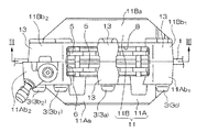
すなわち、アウタ側のキャリパ本体11Aとインナ側のキャリパ本体11Bは、ディスク1を挟み後述するディスクパス部11Ab1、11Ab2、11Bb1、11Bb2でアウタ側とインナ側に分かれたキャリパ本体11A、11Bを複数のタイボルト3,…によって互いに連結したキャリパ11を備える。キャリパ本体11A、11Bは、一対のシリンダ部11Aa、11Baと、一対のディスクパス部11Ab1、11Ab2、11Bb1、11Bb2とから構成されている。一対のシリンダ部11Aa、11Baは、ディスク1を挟んでディスク1の軸線方向に摺動可能に配置される一対の摩擦パッド5、5を、それぞれディスク1に対して押圧するものであって、ディスク1を挟んで配置される。一対のディスクパス部11Ab1、11Ab2、11Bb1、11Bb2は、一対のシリンダ部11Aa、11Ba同士をディスク1の回転方向に前記一対の摩擦パッド5、5が配置されるパッド収容空間8を空けてディスク1を跨いで連結するものである。
【0012】
前記アウタ側及びインナ側のキャリパ本体11A、11Bのボス部13及びディスクパス部11Ab1、11Ab2、11Bb1、11Bb2には、それぞれタイボルト穴11Aca、11Acb1、11Acb2、11Acc、11Bca、11Bcb1、11Bcb2、11Bccが設けられている。
【0013】
ここで、前記一対のディスクパス部のうちディスク1の入側のディスクパス部11Ab1、11Bb1に配される締結部材であるタイボルト3(3c)の数をディスクの出側のディスクパス部11Ab2、11Bb2に配されるタイボルト3(3b1、3b2)の数よりも少なくしてある。具体的には、ディスク1の入側のディスクパス部11Ab1、11Bb1に配されるタイボルト3cの数を1本とし、ディスクの出側のディスクパス部11Ab2、11Bb2に配されるタイボルト3b1、3b2の数を2本としている。したがって、一対のディスクパス部11Ab1、11Ab2、11Bb1、11Bb2に設けるタイボルト穴11Acb1、11Acb2、11Acc、11Bcb1、11Bcb2、11Bccの数もタイボルト3の数に対応させている。
【0014】
つまり、対向ピストン型キャリパ11の略中央に配置されるパッド収容空間8を跨いだ位置であって、該パッド収容空間8の略中央位置が1本のタイボルト3aにより連結され、また、該タイボルト3aによって連結した箇所よりもディスク1の出側(車体取付部7,7が形成されている側)であって、前記パッド収容空間8から外方にずれた位置)が2本のタイボルト3b1,3b2により連結され、さらに、タイボルト3aによって連結した箇所よりもディスク1の入側(車体取付部7,7が形成されている側とは反対側)であって、前記パッド収容空間8から外方にずれた位置)が1本のタイボルト3cにより連結されている。
【0015】
これに対応して、アウタ側のキャリパ本体11Aおよびインナ側のキャリパ本体11Bにそれぞれ形成するタイボルト組付用のボス部13も、タイボルト3(3a,3b,3c)の数並びに位置に合わせて、それらキャリパ本体11A,11Bのディスクパス部11Ab1、11Ab2、11Bb1、11Bb2に設けられている。
一般的に、二輪車は、前進時のみ駆動力が与えられるため、前進状態にある車両を強制的に停止させる場合にはある程度大きな制動力が必要になるが、後進状態にある車両を停止させる場合にはそれほどの制動力は要求されない。このため、二輪車に組み付けるブレーキ装置において、後進状態のブレーキ時に要求される剛性は、前進状態のブレーキ時に要求される剛性よりも小さくてよい。
【0016】
前記ボス部13に設けられるタイボルト穴11Aca、11Acb1、11Acb2、11Acc、11Bca、11Bcb1、11Bcb2、11Bccはディスク1の同心円上に形成されている。図3に示すように、ディスク入側のピストン41の中心点からタイボルト穴11Bcaの中心点を結ぶ線L1と、ディスク入側のピストン41の中心点からタイボルト穴11Bccの中心点を結ぶ線l1とのなす角をθとし、ディスク出側のピストン42の中心点からタイボルト穴11Bcaの中心点を結ぶ線L2と、ディスク出側のピストン42の中心点からタイボルト穴11Bcb1の中心点を結ぶ線l2とのなす角をθ1とし、ディスク出側のピストン42の中心点からタイボルト穴11Bcaの中心点を結ぶ線L2と、ディスク出側のピストン42の中心点からタイボルト穴11Bcb2の中心点を結ぶ線l3とのなす角をθ2とする。
【0017】
このとき、なす角θ、θ1、θ2の関係は、
θ<θ1<θ2
となり、かつ、
L1<l1
となるようにタイボルト穴11Aca、11Acb1、11Acb2、11Acc、11Bca、11Bcb1、11Bcb2、11Bccの位置が規定されている。
上記の如くタイボルト穴11Aca、11Acb1、11Acb2、11Acc、11Bca、11Bcb1、11Bcb2、11Bccの位置を規定することにより、ブレーキ作動時のキャリパ本体の剛性を保ちつつ、小型・軽量化を実現するディスクブレーキとすることができる。
【0018】
また、前述したように、インナ側キャリパ本体2Bのパッド収容空間8の略中央に配置されるタイボルト3aを組み付けるボス部13のホイール側形状13a(図4中斜線で示す部分)は、ディスク1の中心側に向かうに従いホイールに近づくようにテーパー状に傾斜して形成されている(図5〜図8参照)。
【0019】
次に、上記構成のディスクブレーキの作用について説明する。図示せぬブレーキレバーあるいはブレーキペダルが操作されて、シリンダ4,4にブレーキ液圧が導入されると、該シリンダ4,4に嵌挿されている図示せぬピストンの移動に伴い、摩擦バッド5,5がディスク1の左右両側にそれぞれ押し付けられ、これにより、車両に制動力を付与する。
【0020】
ここで、一般に、二輪車は、前進時のみ駆動力が与えられるため、前進状態にある車両を強制的に停止させる場合には、車両の速度や車両の駆動力に比例したある程度大きな制動力が必要になる。一方、後進方向の制動力は、坂道停車時等だけに必要とされるため、前進方向時程の剛性は必要とされない。
上述したディスクブレーキでは、キャリパ11のディスク出側とディスク入側とでは剛性を異ならせている。すなわち、アウタ側とインナ側のキャリパ本体11A,11Bは、ディスク出側で2本のタイボルト3b1,3b2により連結され、ディスク入側では1本のタイボルト3cで連結されている。
【0021】
このように上記ディスクブレーキでは、高い剛性が要求される側、つまりディスク出側のキャリパ部分を、2本のタイボルト3b1,3b2によって強固に連結し、さほど剛性が要求されない側、つまりディスク入側のキャリパ部分を、1本のタイボルト3cによって連結しているので、前述の図9〜図11に示した従来のディスクブレーキに比べ、ディスクブレーキを作動させる上でのキャリパ11に必要な剛性を従来通り確保しつつ、タイボルト3,…の本数を減らすことができる。
【0022】
すなわち、前進時にブレーキを作動させると、摩擦パッド5,5からの制動トルクが、トルク受け部6、および、2本のタイボルト3b1,3b2によって剛性を高められたキャリパ11のディスク出側部分から車体取付部7,7にダイレクトに伝えられ、制動トルクに対するキャリパ11の剛性は従来通り確保される。また、前述したように、従来のものに比べてタイボルト3,…の本数を減らしているので、タイボルト3,…を組み付けるボス部13の数も当然に減少し、これにより、キャリパ11の重量の低減が図れるとともに、前述の従来のディスクブレーキに比べてキャリパ11の小型化が図れ、制動により発生した熱で非常に高温となるディスク1と対向する距離が短くなることから、耐久性の面も優れ、かつ、ベーパーロック現象が生じるおそれが少なくなる。
【0023】
加えて、インナ側のキャリパ本体11Bのパッド収容空間8の略中央に配置されるタイボルト3aを組み付けるボス部13のホイール側形状13aを、ディスク中心側に向かうに従いホイール14に近づくようにテーパー状に傾斜して形成しているので、キャリパ11の脱着作業が容易に行える。
すなわち、図6〜図8に示すように、例えば、キャリパ11を車体から取り外す際には、該キャリパ11の車体取付部7,7に締結してあるボルトを外した後、図7に示すように、摩擦バッド5の下端がディスク1の外周部との係合を解かれる位置まで、キャリパ11を引き上げる。このとき、キャリパ11のテーパー状に傾斜して形成されているボス部13のホイール側形状13aが、ホイール14に当接する。この状態から、キャリパ11をさらに引き上げると、前記ボス部13のホイール側形状13aがホイール14に当接されたまま該ホイール14に案内されることとなり、特に、キャリパ11の上部がホイール14の幅方向外方へ自動的にずらされる(図8参照)。この結果、キャリパ9の取り外し作業が容易に行える。また、キャリパ9を車体側に取り付けるには、前述とは逆の作業を行いつつ、キャリパのボス部13のホイール側形状13aをホイール14に当接させることで、キャリパ11の取付作業が容易に行えるのである。
【0024】
また、前述のようにボス部13のホイール側形状13aをテーパー状に傾斜して形成しているから、該テーパー状の傾斜部分がボス部とシリンダ部とを連結するリブとして機能することとなり、キャリパ11の剛性が向上する利点も得られる。
【0025】
なお、上述した実施の形態はあくまで本発明の例示であり、必要に応じて適宜設計変更可能である。
例えば、前記実施の形態では、アウタ側のキャリパ本体11Aとインナ側のキャリパ本体11Bのパッド収容空間8を跨いだ位置には、該パッド収容空間8の略中央位置に1本のタイボルト3aを配置しているが、ここに配置するタイボルトの数は必ずしも1本に限ることなく、例えば2本であってもよい。
また、前記実施の形態では、パッド収容空間8に跨いだ位置に配置したタイボルト3aにより連結した箇所よりもディスク1の周方向一側に2本のタイボルト3b1,3b2を、また、タイボルト3aによって連結した箇所よりもディスク1の周方向他側に1本のタイボルト3cを配置しているが、これらタイボルトの数は必ずしも1本と2本に限られることはない。要は、キャリパ11の、パッド収容空間8に跨いだ位置に配置したタイボルト3aによって連結した箇所よりもディスクの周方向一側に配置するタイボルト3の本数と、タイボルト3aによって連結した箇所のディスク1の周方向の他側に配置するタイボルト3の本数を異ならせれば足りる。
【0026】
【発明の効果】
以上説明したように、本発明によれば、次の効果が得られる。
(イ) 従来のディスクブレーキに対して、タイボルト等の締結部材の数が減るため、部品点数が減少し、かつ、キャリパの小型・軽量化が図れる。
(ロ) 必要な箇所のみ締結部材の数を保ってキャリパ本体の剛性を維持しつつ、不必要な個所の締結部材の数を減少することによってコストを低減できる。
(ハ) キャリパに設ける、締結部材を嵌合させるための穴やネジ加工部分が減少するので加工費が低減できる。
(ニ) 摩擦パッドからの制動トルクが、締結部材によって剛性を高められたキャリパのディスク出側から車体側にダイレクトに伝えられるため、制動トルクに対するキャリパの剛性は従来通り確保される。
【図面の簡単な説明】
【図1】 本発明の実施の形態を示すディスクブレーキの平面図である。
【図2】 本発明の実施の形態を示すディスクブレーキの正面図である。
【図3】 図1のIII-III線に沿う断面図である。
【図4】 本発明の実施の形態を示すディスクブレーキの背面図である。
【図5】 本発明の実施の形態を示すディスクブレーキの側面図である。
【図6】 本発明の実施の形態を示すディスクブレーキの取付状況を示す側面図である。
【図7】 本発明の実施の形態を示すディスクブレーキの取付状況を示す側面図である。
【図8】 本発明の実施の形態を示すディスクブレーキの取付状況を示す側面図である。
【図9】 従来のディスクブレーキの平面図である。
【図10】 従来のディスクブレーキの正面図である。
【図11】 図9のXI-XI線に沿う断面図である。
【符号の説明】
1 ディスク
3(3a、3b1、3b2、3c) タイボルト(締結部材)
5 摩擦バッド
8 パッド収容空間 11 キャリパ
11A アウタ側キャリパ本体 11B インナ側キャリパ本体
11Aa、11Ba シリンダ部
11Ab1、11Ab2、11Bb1、11Bb2 ディスクパス部
13 ボス部 13a ボス部のホイール側形状[0001]
BACKGROUND OF THE INVENTION
The present invention relates to a disc brake used for braking a vehicle or the like.
[0002]
[Prior art]
Some disc brakes have an opposed piston type caliper. This type of disc brake, as shown in FIGS. 9 to 11, the disk path portion 2Ab 1, 2Ab 2, 2Bb 1 ,
A
Further, the braking torque at this time acts as a force for moving the
[0003]
By the way, in this type of disc brake, in recent years, in order to increase the pad area, the pad accommodating space 8 which is a place where the
The
[0004]
In the conventional disc brake described above, the wheel-
[0005]
[Problems to be solved by the invention]
However, the conventional disc brake has the following problems.
(A) Since the
(B) In order to increase the rigidity of the
(C) The tie bolt holes 2Ac, 2Bc for inserting the
[0006]
An object of the present invention is to solve the above-mentioned problems, and to provide a disc brake that can be reduced in size and weight while maintaining the rigidity of the caliper body, and can reduce costs. Objective.
[0007]
[Means for Solving the Problems]
In order to achieve at least one of the above objects, the invention according to
One tie bolt hole into which the fastening member is inserted is provided in the boss part, one in the disk path part on the entry side of the disk, and two on the disk path part on the exit side of the disk,
Of the two pistons, a line connecting the center point of the piston on the disk entry side to the center point of the tie bolt hole provided in the boss part and the disk path part on the disk entry side from the center point of the piston on the disk entry side The angle formed with the line connecting the center points of the tie bolt holes provided in
Of the two pistons, a line connecting a center point of the piston on the disk exit side to a center point of a tie bolt hole provided in the boss part and a disk path part on the exit side of the disk from the center point of the piston on the disk exit side The angle between the two tie bolt holes provided in the tie bolt hole and the line connecting the center points of the tie bolt holes provided on the end side of the caliper body is smaller .
[0008]
In the first aspect of the present invention described above, the number of fastening members disposed in the disk path portion on the entry side of the disk among the pair of disk path portions of the caliper is determined by the fastening member disposed on the disk path portion on the exit side of the disk. Therefore, the rigidity is different between the disk entrance side and the disk exit side of the disk path portion in a state where they are connected by these fastening members. In other words, the invention according to
Further, in the invention of
As a result, it is possible to reduce the size and weight while maintaining the rigidity of the caliper body when the brake is operated.
[0009]
DETAILED DESCRIPTION OF THE INVENTION
Embodiments of the present invention will be described with reference to the accompanying drawings.
1 to 8 show an embodiment of a disc brake according to the present invention. This disc brake is different from the conventional disc brake in that the number of
Since the other structure is the same as that of the conventional disc brake, the same reference numerals are assigned to the same members and the description thereof is omitted.
[0010]
In the disc brake of this embodiment, the outer side and inner
[0011]
That is, the
[0012]
The outer side and the inner side of the
[0013]
Here, of the pair of disk path portions, the number of tie bolts 3 (3c) which are fastening members arranged on the disk path portions 11Ab 1 and 11Bb 1 on the entry side of the disk 1 is set to the disk path portion 11Ab on the exit side of the disk. 2 and 11Bb 2 are less than the number of tie bolts 3 (3b 1 , 3b 2 ). Specifically, the number of
[0014]
That is, it is a position straddling the pad accommodating space 8 disposed substantially at the center of the
[0015]
Correspondingly, the
Generally, since a motorcycle is given a driving force only during forward movement, a certain amount of braking force is required to forcibly stop a vehicle in a forward movement state, but in a case of stopping a vehicle in a reverse movement state. Does not require that much braking power. For this reason, in the brake device assembled to the two-wheeled vehicle, the rigidity required at the time of braking in the reverse traveling state may be smaller than the rigidity required at the time of braking in the forward traveling state.
[0016]
Tie bolt holes 11 Aca, 11 Acb 1 , 11 Acb 2 , 11 Acc, 11 Bca, 11 Bcb 1 , 11 Bcb 2 , 11 Bcc provided in the
[0017]
At this time, the relationship between the angles θ, θ 1 and θ 2 is
θ <θ 1 <θ 2
And
L 1 <l 1
Become as tie bolt hole 11Aca, 11Acb 1, 11Acb 2, 11Acc, 11Bca,
The above as tie-bolts holes 11Aca, 11Acb 1, 11Acb 2, 11Acc, 11Bca, by defining the position of 11Bcb 1, 11Bcb 2, 11Bcc, while maintaining the rigidity of the caliper body during braking, reduce the size and weight Can be a disc brake.
[0018]
Further, as described above, the wheel-
[0019]
Next, the operation of the disc brake having the above configuration will be described. When a brake hydraulic pressure is introduced into the
[0020]
Here, in general, since a driving force is applied to a two-wheeled vehicle only when moving forward, a certain amount of braking force proportional to the vehicle speed or the driving force of the vehicle is required to forcibly stop a vehicle that is moving forward. become. On the other hand, since the braking force in the reverse direction is required only when the vehicle stops on a slope, the rigidity in the forward direction is not required.
In the disc brake described above, the rigidity of the
[0021]
As described above, in the above-described disc brake, the caliper portion on the side where high rigidity is required, that is, the disc exit side, is firmly connected by the two
[0022]
That is, when the brake is operated at the time of forward movement, the braking torque from the
[0023]
In addition, the
That is, as shown in FIGS. 6 to 8, for example, when the
[0024]
Moreover, since the
[0025]
The above-described embodiment is merely an example of the present invention, and the design can be changed as appropriate.
For example, in the above-described embodiment, one
Further, in the above embodiment, the two
[0026]
【The invention's effect】
As described above, according to the present invention, the following effects can be obtained.
(A) Since the number of fastening members such as tie bolts is reduced compared to the conventional disc brake, the number of parts is reduced, and the caliper can be reduced in size and weight.
(B) The cost can be reduced by reducing the number of unnecessary fastening members while maintaining the rigidity of the caliper main body by maintaining the number of fastening members only at necessary portions.
(C) Since the number of holes and threaded portions for fitting the fastening members provided in the caliper are reduced, the processing cost can be reduced.
(D) Since the braking torque from the friction pad is directly transmitted from the disk exit side of the caliper whose rigidity is enhanced by the fastening member to the vehicle body side, the rigidity of the caliper with respect to the braking torque is ensured as before.
[Brief description of the drawings]
FIG. 1 is a plan view of a disc brake showing an embodiment of the present invention.
FIG. 2 is a front view of a disc brake showing an embodiment of the present invention.
3 is a cross-sectional view taken along line III-III in FIG.
FIG. 4 is a rear view of the disc brake showing the embodiment of the present invention.
FIG. 5 is a side view of a disc brake showing an embodiment of the present invention.
FIG. 6 is a side view showing a mounting state of the disc brake according to the embodiment of the present invention.
FIG. 7 is a side view showing a mounting state of the disc brake according to the embodiment of the present invention.
FIG. 8 is a side view showing a mounting state of the disc brake showing the embodiment of the present invention.
FIG. 9 is a plan view of a conventional disc brake.
FIG. 10 is a front view of a conventional disc brake.
11 is a cross-sectional view taken along line XI-XI in FIG.
[Explanation of symbols]
1
5 Friction Bad 8
Claims (2)
該摩擦パッドをそれぞれディスクに対して押圧するために前記ディスクの回転方向に並んで配設される2つのピストンを有して、ディスクを挟んで対向配置される一対のシリンダ部と、
前記ディスクの回転方向に前記摩擦パッドが配置されるパッド収容空間を空けて一対設けられ、前記一対のシリンダ部同士をディスクを跨いで連結するディスクパス部と、からなり、
前記一対のシリンダ部及びディスクパス部とから構成されるキャリパ本体を予めディスクパス部で車両のインナ側とアウタ側とで分割するとともに、該インナ側キャリパ本体及びアウタ側キャリパ本体それぞれにディスクの回転方向で前記2つのピストンの間で連結されるボス部を形成し、
締結部材を前記一対のディスクパス部及び前記ボス部に配して前記インナ側キャリパ本体とアウタ側キャリパ本体とを一体化してなるディスクブレーキにおいて、
前記一対のディスクパス部のうちディスクの入側のディスクパス部に配される締結部材の数をディスクの出側のディスクパス部に配される締結部材の数よりも少なくしてなり、
前記締結部材が差し込まれるタイボルト穴が、前記ボス部に1つ、前記ディスクの入側のディスクパス部に1つ、前記ディスクの出側のディスクパス部に2つそれぞれ設けられ、
前記2つのピストンのうちディスク入側のピストンの中心点から前記ボス部に設けられたタイボルト穴の中心点を結ぶ線と前記ディスク入側のピストンの中心点から前記ディスクの入側のディスクパス部に設けられたタイボルト穴の中心点を結ぶ線とのなす角を、
前記2つのピストンのうちディスク出側のピストンの中心点から前記ボス部に設けられたタイボルト穴の中心点を結ぶ線と前記ディスク出側のピストンの中心点から前記ディスクの出側のディスクパス部に設けられた2つのタイボルト穴のうち前記キャリパ本体の端部側に設けられたタイボルト穴の中心点を結ぶ線とのなす角よりも小さくしたことを特徴とするディスクブレーキ。Friction pads that are slidable in the axial direction of the disc on both sides of the disc,
A pair of cylinders arranged opposite to each other with the two discs arranged in the rotational direction of the disc to press the friction pads against the disc,
A pair of discs provided between the pair of cylinders across the discs, with a pair of pad accommodating spaces in which the friction pads are arranged in the rotational direction of the discs;
The caliper body composed of the pair of cylinder parts and the disk path part is divided in advance into the inner side and the outer side of the vehicle at the disk path part, and the disk is rotated to each of the inner side caliper body and the outer side caliper body. Forming a boss connected in a direction between the two pistons,
In disc brakes of conclude member by disposing the pair of disc-path portion and the boss portion formed by integrating the said inner caliper body and the outer caliper body,
Of the pair of disk path parts, the number of fastening members arranged in the disk path part on the entry side of the disk is smaller than the number of fastening members arranged on the disk path part on the exit side of the disk ,
One tie bolt hole into which the fastening member is inserted is provided in the boss part, one in the disk path part on the entry side of the disk, and two on the disk path part on the exit side of the disk,
Of the two pistons, a line connecting the center point of the piston on the disk entry side to the center point of the tie bolt hole provided in the boss part and the disk path part on the disk entry side from the center point of the piston on the disk entry side The angle formed with the line connecting the center points of the tie bolt holes provided in
Of the two pistons, a line connecting a center point of the piston on the disk exit side to a center point of a tie bolt hole provided in the boss part and a disk path part on the exit side of the disk from the center point of the piston on the disk exit side A disc brake characterized in that it is smaller than an angle formed by a line connecting the center points of the tie bolt holes provided on the end portion side of the caliper main body of the two tie bolt holes provided in the tie bolt hole .
Priority Applications (1)
| Application Number | Priority Date | Filing Date | Title |
|---|---|---|---|
| JP2000082970A JP4510217B2 (en) | 2000-03-23 | 2000-03-23 | Disc brake |
Applications Claiming Priority (1)
| Application Number | Priority Date | Filing Date | Title |
|---|---|---|---|
| JP2000082970A JP4510217B2 (en) | 2000-03-23 | 2000-03-23 | Disc brake |
Publications (3)
| Publication Number | Publication Date |
|---|---|
| JP2001271856A JP2001271856A (en) | 2001-10-05 |
| JP2001271856A5 JP2001271856A5 (en) | 2006-11-16 |
| JP4510217B2 true JP4510217B2 (en) | 2010-07-21 |
Family
ID=18599701
Family Applications (1)
| Application Number | Title | Priority Date | Filing Date |
|---|---|---|---|
| JP2000082970A Expired - Fee Related JP4510217B2 (en) | 2000-03-23 | 2000-03-23 | Disc brake |
Country Status (1)
| Country | Link |
|---|---|
| JP (1) | JP4510217B2 (en) |
Citations (2)
| Publication number | Priority date | Publication date | Assignee | Title |
|---|---|---|---|---|
| JPH04109695U (en) * | 1991-03-08 | 1992-09-22 | 日信工業株式会社 | disc brake |
| JPH04341622A (en) * | 1991-01-17 | 1992-11-27 | Tokico Ltd | Disc brake |
-
2000
- 2000-03-23 JP JP2000082970A patent/JP4510217B2/en not_active Expired - Fee Related
Patent Citations (2)
| Publication number | Priority date | Publication date | Assignee | Title |
|---|---|---|---|---|
| JPH04341622A (en) * | 1991-01-17 | 1992-11-27 | Tokico Ltd | Disc brake |
| JPH04109695U (en) * | 1991-03-08 | 1992-09-22 | 日信工業株式会社 | disc brake |
Also Published As
| Publication number | Publication date |
|---|---|
| JP2001271856A (en) | 2001-10-05 |
Similar Documents
| Publication | Publication Date | Title |
|---|---|---|
| JP3848525B2 (en) | Motorcycle braking device | |
| KR101294035B1 (en) | Structure of axle assembly for a driving wheel | |
| JPH0520904Y2 (en) | ||
| JP4510217B2 (en) | Disc brake | |
| GB2473001A (en) | Disc Brake Caliper Body having a cooling aperture | |
| JP4461082B2 (en) | Caliper body for disc brakes for vehicles | |
| JP2900254B2 (en) | Disc brake device for vehicles | |
| JP4108853B2 (en) | Disc brake | |
| GB2032546A (en) | An improved braking arrangement | |
| JPH1163041A (en) | Caliper body for vehicle disc brake | |
| JP4139039B2 (en) | Caliper body mounting structure for vehicle disc brakes | |
| JP3949780B2 (en) | brake disc | |
| JPS633587Y2 (en) | ||
| JP2001280377A (en) | Caliper body mounting structure of disc brake for vehicle | |
| CN113165608A (en) | Vehicle brake | |
| JPH0121096Y2 (en) | ||
| JP3035747B2 (en) | Disc brake device for vehicles | |
| JPH0650661Y2 (en) | Opposite multi-pot caliper for vehicle disc brakes | |
| JP4293708B2 (en) | Mounting structure for vehicle disc brake | |
| JP4818307B2 (en) | Disc brake for radial mount type vehicle | |
| KR0112155Y1 (en) | Disk brake | |
| JP3023777U (en) | Disc brake caliper | |
| KR100874801B1 (en) | Automotive facing caliper brakes | |
| JPH10267054A (en) | Disc brake having parking drum brake | |
| KR0174521B1 (en) | Disk heat radiant structure of car brake |
Legal Events
| Date | Code | Title | Description |
|---|---|---|---|
| A711 | Notification of change in applicant |
Free format text: JAPANESE INTERMEDIATE CODE: A712 Effective date: 20041126 |
|
| A521 | Written amendment |
Free format text: JAPANESE INTERMEDIATE CODE: A523 Effective date: 20060928 |
|
| A621 | Written request for application examination |
Free format text: JAPANESE INTERMEDIATE CODE: A621 Effective date: 20060928 |
|
| A977 | Report on retrieval |
Free format text: JAPANESE INTERMEDIATE CODE: A971007 Effective date: 20080926 |
|
| A131 | Notification of reasons for refusal |
Free format text: JAPANESE INTERMEDIATE CODE: A131 Effective date: 20081125 |
|
| A521 | Written amendment |
Free format text: JAPANESE INTERMEDIATE CODE: A523 Effective date: 20090126 |
|
| A131 | Notification of reasons for refusal |
Free format text: JAPANESE INTERMEDIATE CODE: A131 Effective date: 20090714 |
|
| A711 | Notification of change in applicant |
Free format text: JAPANESE INTERMEDIATE CODE: A712 Effective date: 20090901 |
|
| RD03 | Notification of appointment of power of attorney |
Free format text: JAPANESE INTERMEDIATE CODE: A7423 Effective date: 20090901 |
|
| A521 | Written amendment |
Free format text: JAPANESE INTERMEDIATE CODE: A523 Effective date: 20090904 |
|
| A521 | Written amendment |
Free format text: JAPANESE INTERMEDIATE CODE: A523 Effective date: 20090910 |
|
| TRDD | Decision of grant or rejection written | ||
| A01 | Written decision to grant a patent or to grant a registration (utility model) |
Free format text: JAPANESE INTERMEDIATE CODE: A01 Effective date: 20100423 |
|
| A01 | Written decision to grant a patent or to grant a registration (utility model) |
Free format text: JAPANESE INTERMEDIATE CODE: A01 |
|
| A61 | First payment of annual fees (during grant procedure) |
Free format text: JAPANESE INTERMEDIATE CODE: A61 Effective date: 20100430 |
|
| FPAY | Renewal fee payment (event date is renewal date of database) |
Free format text: PAYMENT UNTIL: 20130514 Year of fee payment: 3 |
|
| R150 | Certificate of patent or registration of utility model |
Free format text: JAPANESE INTERMEDIATE CODE: R150 |
|
| FPAY | Renewal fee payment (event date is renewal date of database) |
Free format text: PAYMENT UNTIL: 20130514 Year of fee payment: 3 |
|
| FPAY | Renewal fee payment (event date is renewal date of database) |
Free format text: PAYMENT UNTIL: 20140514 Year of fee payment: 4 |
|
| LAPS | Cancellation because of no payment of annual fees |