JP4508517B2 - Three-dimensional image composition apparatus and method, and information storage medium - Google Patents
Three-dimensional image composition apparatus and method, and information storage medium Download PDFInfo
- Publication number
- JP4508517B2 JP4508517B2 JP2002095813A JP2002095813A JP4508517B2 JP 4508517 B2 JP4508517 B2 JP 4508517B2 JP 2002095813 A JP2002095813 A JP 2002095813A JP 2002095813 A JP2002095813 A JP 2002095813A JP 4508517 B2 JP4508517 B2 JP 4508517B2
- Authority
- JP
- Japan
- Prior art keywords
- light source
- game
- random number
- coordinates
- illuminated
- Prior art date
- Legal status (The legal status is an assumption and is not a legal conclusion. Google has not performed a legal analysis and makes no representation as to the accuracy of the status listed.)
- Expired - Lifetime
Links
Images


Description
【0001】
【発明の属する技術分野】
本発明は3次元画像合成装置並びに方法及び情報記憶媒体に関し、特に3次元オブジェクトに対するシェーディングやシャドウィングを軽い処理負荷で実施する技術に関する。
【0002】
【従来の技術】
3次元画像合成処理では、オブジェクト空間(仮想3次元空間)に光源を設定し、そこから光線を仮想的に放射させることにより、オブジェクトにシェーディングやシャドウィングを施している。こうすれば、2次元画面であってもオブジェクトを立体的に表示することができる。
【0003】
【発明が解決しようとする課題】
しかしながら、シェーディングやシャドウィング等の光源を用いる画像処理は計算量が多く、多数の光源がオブジェクト空間に設定される場合や、反射面が複雑な場合には、リアルタイムに表示画像を生成することが困難となる。例えば、火災現場に立つ人の顔のように多数の光源により照光されたオブジェクトの描画や、波打つ水面からの反射光を受けた人の顔のように多方面からの反射光により照光されたオブジェクトの描画は、計算量が膨大となってしまう。
【0004】
本発明は上記課題に鑑みてなされたものであって、その目的は、比較的軽い処理負荷で多方面からの光を受けたオブジェクトの画像を十分な品質で生成することのできる3次元画像合成装置並びに方法及び情報記憶媒体を提供することにある。
【0005】
【課題を解決するための手段】
上記課題を解決するために、本発明に係る3次元画像合成装置は、照光対象のオブジェクトに係る座標を取得する座標取得手段と、前記座標に所定軌道を表すベクトルを加算し、さらに乱数に基づくベクトルを加算することにより、乱数により歪められた前記所定軌道上に不可視の光源の座標を設定する光源座標設定手段と、前記不可視の光源に基づいて前記照光対象のオブジェクトに関する表示画像を形成する表示画像形成手段と、を含むことを特徴とする。
【0006】
また、本発明に係る3次元画像合成方法は、照光対象のオブジェクトに係る座標を取得するステップと、前記座標に所定軌道を表すベクトルを加算し、さらに乱数に基づくベクトルを加算することにより、乱数により歪められた前記所定軌道上に不可視の光源の座標を設定するステップと、前記不可視の光源に基づいて前記照光対象のオブジェクトに関する表示画像を形成するステップと、を含むことを特徴とする。
【0007】
また、本発明に係る情報記憶媒体は、照光対象のオブジェクトに係る座標を取得するステップと、前記座標に所定軌道を表すベクトルを加算し、さらに乱数に基づくベクトルを加算することにより、乱数により歪められた前記所定軌道上に不可視の光源の座標を設定するステップと、前記不可視の光源に基づいて前記照光対象のオブジェクトに関する表示画像を形成するステップと、をコンピュータに実行させるためのプログラムを格納したものである。
【0008】
また、本発明の一態様では、乱数に基づいて前記不可視の光源の光の色を設定する光源情報設定手段をさらに含む。
【0012】
【発明の実施の形態】
以下、本発明の好適な実施の形態について図面に基づき詳細に説明する。
【0013】
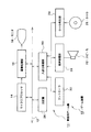
図1は、本発明の一実施形態に係るゲーム装置の構成を示す図である。同図に示すゲーム装置10は、本発明に係る3次元画像合成装置の実施形態の1つであり、モニタ18及びスピーカ22に接続された家庭用ゲーム機11に、情報記憶媒体たるDVD25が装着されることにより構成される。ここでは、ゲームプログラムやゲームデータを家庭用ゲーム機11に供給するためにDVD25を用いるが、CD−ROMやROMカード等、他のあらゆる情報記憶媒体を用いることができる。また、後述するように、通信ネットワークを介して遠隔地からゲームプログラムやゲームデータを家庭用ゲーム機11に供給することもできる。以下では、このゲーム装置10の説明を通して、本発明に係る3次元画像合成装置、3次元画像合成方法及び情報記憶媒体について説明する。
【0014】
家庭用ゲーム機11は、マイクロプロセッサ14、画像処理部16、主記憶26及び入出力処理部30がバス12により相互データ通信可能に接続され、さらに入出力処理部30には、コントローラ32、音声処理部20及びDVD再生部24が接続されている。コントローラ32以外の家庭用ゲーム機11の各構成要素は筐体内に収容されている。モニタ18には例えば家庭用のテレビ受像機が用いられ、スピーカ22には例えばその内蔵スピーカが用いられる。
【0015】
マイクロプロセッサ14は、図示しないROMに格納されるオペレーティングシステムやDVD25から読み出されるゲームプログラムに基づいて、家庭用ゲーム機11の各部を制御する。バス12はアドレス及びデータを家庭用ゲーム機11の各部でやり取りするためのものである。また、主記憶26には、DVD25から読み取られたゲームプログラム及びゲームデータが必要に応じて書き込まれる。画像処理部16はVRAMを含んで構成されており、マイクロプロセッサ14から送られる画像データを受け取ってVRAM上にゲーム画面を描画するとともに、その内容を所定のビデオ信号に変換して所定タイミングでモニタ18に出力する。すなわち画像処理部16は、マイクロプロセッサ14から視点座標系での各ポリゴンの頂点座標(X,Y,Z)、頂点色情報(R,G,B)、テクスチャ座標(VX,VY)及びアルファ値等を受け取る。そして、それら情報を用いて表示画像を構成する各ピクセルの色情報、Z値及びアルファ値等をVRAMに描画する。このとき、例えば頂点色情報をピクセル単位で補間して用いることによりグーローシェーディングが実施される。この表示画像は所定タイミングでモニタ18に出力される。
【0016】
入出力処理部30はコントローラ32、音声処理部20及びDVD再生部24とマイクロプロセッサ14との間のデータ通信を中継するためのインターフェースである。コントローラ32はプレイヤーがゲーム操作をするための入力手段である。入出力処理部30は一定周期(例えば1/60秒毎)にコントローラ32の各種ボタンの操作状態をスキャンし、そのスキャン結果を表す操作信号をバス12を介してマイクロプロセッサ14に渡す。マイクロプロセッサ14は、その操作信号に基づいてプレイヤーのゲーム操作を判定する。音声処理部20はサウンドバッファを含んで構成されており、DVD25から読み出されてサウンドバッファに記憶された音楽やゲーム効果音等のデータを再生してスピーカ22から出力する。DVD再生部24は、マイクロプロセッサ14からの指示に従ってDVD25に記録されたゲームプログラム及びゲームデータを読み取る。
【0017】
以下、かかる構成を有するゲーム装置10を用い、火災現場に立つゲームキャラクターにシェーディング及びシャドウィングを施す技術について説明する。
【0018】
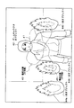
図2は、ゲーム装置10のモニタ18に表示されるゲーム画像の一例を示す図である。同図に示すように、ゲーム空間(オブジェクト空間)には床面が設定され、その上にゲームキャラクタオブジェクト42が設置されている。ゲームキャラクタオブジェクト42は画面中央に手前側を向くよう表示されており、その背後には炎オブジェクト44a〜44cが配置されている。ゲームキャラクタオブジェクト42の周りには光源軌道41が設定されており、その光源軌道41上を動的光源40が移動している。光源軌道41は、例えば楕円軌道を基本とするものであり、それが乱数により歪められている。すなわち、楕円軌道上の座標に乱数により定められる3次元ベクトルが加算されて、そこに動的光源40が配置される。こうして、光源軌道41を不規則なものとすることができる。また、動的光源40は色情報(色、光の強さ)が乱数により設定されている。例えば黄色から赤色の間で揺らめくように乱数により色情報が設定される。
【0019】
さらに、炎オブジェクト44a〜44cのいずれかの内部には静的光源43が設定される。図3は、静的光源43の設定処理を説明する図である。ゲーム装置10ではゲームプログラムに基づいてマイクロプロセッサ14がゲームキャラクタオブジェクト42の座標(例えば顔部分の座標)と炎オブジェクト44a〜44cの座標との距離La〜Lcを算出し、最も距離の短い炎オブジェクト44の内部に静的光源43を設定する。静的光源43も色情報(色、光の強さ)が乱数により設定されている。例えば黄色から赤色の間で揺らめくように乱数により色情報が設定される。
【0020】
図4は、ゲーム装置10で実行されるゲーム処理について説明するフロー図である。同図に示すように、ゲーム装置10ではマイクロプロセッサ14がDVD25から読み出されるゲームプログラム及びゲームデータに基づき、まずゲーム環境処理を行う(S101)。ゲーム環境処理では、仮想3次元空間のすべての静的オブジェクト及び動的オブジェクトの位置及び姿勢が演算される。静的オブジェクトは炎オブジェクト44a〜44c等のようにゲームが進行しても位置を変えないものである。これに対して動的オブジェクトはゲームキャラクタオブジェクト42のようにゲームが進行するにつれて位置や姿勢を変えるものである。動的オブジェクトの位置及び姿勢は、ゲームプログラムやコントローラ32から入力される操作信号に従って変化する。また、ゲーム環境処理では視点や視野範囲も計算される。そして、視野範囲から離れたオブジェクトについては以降のゲーム処理の対象から除外される。
【0021】
次に、マイクロプロセッサ14は光源設定処理を行う(S102)。光源設定処理ではゲームキャラクタオブジェクト42の周囲に動的光源40を設定し、さらに炎オブジェクト44a〜44cのいずれかの内部に静的光源43を設定する。
【0022】
さらに、マイクロプロセッサ14はジオメトリ処理を行う(S103)。ジオメトリ処理ではワールド座標系から視点座標系への座標変換を行う。また、オブジェクトを構成する各ポリゴンの頂点の色情報が光源情報(光源の色及び位置)に基づいて修正される。ここで用いる光源情報は、S102で設定した動的光源40及び静的光源43に関するものの他、ゲームデータにより予め設定されている光源に関するものも含まれる。ジオメトリ処理では、さらにクリッピング処理も行われる。
【0023】
その後、マイクロプロセッサ14は視野範囲に属する各ポリゴンの頂点座標、頂点色情報、テクスチャ座標及びアルファ値を画像処理部16に送出し、画像処理部16ではそれらの情報に基づいてVRAM上に設けられた表示用バッファに表示画像を形成する(S104)。表示用バッファに形成された画像は所定タイミングで読み出されて、モニタ18により表示される。モニタ18に表示される画像は動的光源40や静的光源43を用いてシェーディング及びシャドウィングされたものとなる。
【0024】
ここで、S102(図4)の光源設定処理についてさらに詳しく説明する。図5は、光源設定処理を説明するフロー図である。光源設定処理では、まずマイクロプロセッサ14がゲームキャラクタオブジェクト42の胸部座標を取得する(S201)。この座標はS101(図4)のゲーム環境処理で設定されたものである。次に、マイクロプロセッサ14は公知技術により乱数を生成する(S202)。そして、キャラクタ胸部付近に動的光源40を設定する(S203)。具体的には、ゲームキャラクタオブジェクト42の胸部座標に楕円軌道を表すベクトルを加算し、さらに乱数に基づくベクトルを加算することにより動的光源40の位置を決定する。ここでは楕円軌道を用いるが、ゲームキャラクタオブジェクト42の周囲の乱数に基づく位置に動的光源40を設定するのであれば、どのような手順を採用してもよい。また、このとき動的光源40の色情報を乱数を用いて設定する。乱数を用いなくとも、所定周期で色が変化するようにしてもよい。動的光源40の色情報としては、炎の色として相応しい範囲に設定される。
【0025】
さらにマイクロプロセッサ14はゲームキャラクタオブジェクト42の胸部座標と炎オブジェクト44a〜44cの座標との距離La〜Lcを算出する(S204)。そして、最もゲームキャラクタオブジェクト42の胸部座標に近い位置に配置されている炎オブジェクト44a〜44cのうち1つに静的光源43を設定する(S205)。静的光源43の色情報も乱数を用いて設定する。静的光源43についても、乱数を用いず、所定周期で色が変化するようにしてよい。静的光源43の色情報も、炎の色として相応しい範囲に設定される。
【0026】
以上説明したゲーム装置10によれば、炎オブジェクト44a〜44cの座標が静的光源43の位置の候補とされており、ゲームキャラクタオブジェクト42がオブジェクト空間を移動するにしたがって、もっとも近いものが実際に静的光源43の位置として選択される。このため、ゲームキャラクタオブジェクト42のレンダリングに影響の大きい光源だけを実際に用いて、その他の影響の少ない光源を省略することができる。また、乱数により静的光源43の色情報を変化させているので、炎の光が揺らめく様子を好適に演出することができる。
【0027】
さらに、以上のゲーム装置10では、動的光源40をゲームキャラクタオブジェクト42の胸部周辺で動的光源40がランダムに移動するようにしているので、ゲームキャラクタオブジェクト42に最も近い炎オブジェクト44以外の炎オブジェクト44から発せられるべき光を動的光源40に肩代わりさせることができる。こうして、ゲームキャラクタオブジェクト42の顔に炎の色が写り込む様子を少ない光源数で好適に演出することができる。また、乱数により動的光源40の色情報を変化させているので、炎の光が揺らめく様子を好適に演出することができる。
【0028】
なお、本発明は以上の実施の形態に限定されるものではない。
【0029】
例えば、以上の説明ではゲームキャラクタオブジェクト42が火災現場に立っている状況を画像表示する技術を説明したが、波打つ水面近くのオブジェクト(例えばゲームキャラクタオブジェクト)に反射光があたる様子を演出する場合にも、同様に適用可能である。この場合は光源の色情報として水面での反射光として相応しい範囲のものが設定される。
【0030】
また、以上の説明は本発明を家庭用ゲーム機11を用いて実施する例についてのものであるが、業務用ゲーム装置にも本発明は同様に適用可能である。この場合、DVD25及びDVD再生部24に代えてより高速な記憶装置を用い、モニタ18やスピーカ22も一体的に形成することが望ましい。
【0031】
また、以上の説明ではゲームプログラム及びゲームデータを格納したDVD25を家庭用ゲーム機11で使用するようにしたが、パーソナルコンピュータ等、ゲームプログラム及びゲームデータを記録した情報記憶媒体を読み取って、その読み取った内容に基づく情報処理が可能なコンピュータであれば、どのようなものでも使用することができる。
【0032】
また、本発明はゲームに関わる画像処理に限らず、あらゆる3次元画像処理に適用可能である。例えば、3次元CGアニメーション、フライトシミュレータ、ドライブシミュレータ等にも本発明を適用可能である。
【0033】
さらに、以上の説明ではゲームプログラム及びゲームデータを情報記憶媒体たるDVD25から家庭用ゲーム機11に供給するようにしたが、通信ネットワークを介してゲームプログラム及びゲームデータを家庭等に配信することもできる。図6は、通信ネットワークを用いたゲームプログラム配信システムの全体構成を示す図である。同図に基づいて本発明に係るプログラム配信装置及び方法を説明する。同図に示すように、このゲームプログラム配信システム100は、ゲームデータベース102、サーバ104、通信ネットワーク106、パソコン108、家庭用ゲーム機110、PDA(携帯情報端末)112を含んでいる。このうち、ゲームデータベース102とサーバ104とによりゲームプログラム配信装置114が構成される。通信ネットワーク106は、例えばインターネットやケーブルテレビネットワークである。このシステムでは、ゲームデータベース102に、DVD25の記憶内容と同様のゲームプログラム及びゲームデータが記憶されている。そして、パソコン108、家庭用ゲーム機110又はPDA112等を用いて需要者がゲーム配信要求をすることにより、それが通信ネットワーク106を介してサーバ104に伝えられる。そして、サーバ104はゲーム配信要求に応じてゲームデータベース102からゲームプログラム及びゲームデータを読み出し、それをパソコン108、家庭用ゲーム機110又はPDA112等、ゲーム配信要求元に送信する。ここではゲーム配信要求に応じてゲーム配信するようにしたが、サーバ104から一方的に送信するようにしてもよい。また、必ずしも一度にゲームの実現に必要な全てのゲームプログラム及びゲームデータを配信する必要はなく、ゲームの局面に応じて必要な部分を配信するようにしてもよい。このように通信ネットワーク106を介してゲーム配信するようにすれば、ゲームプログラム及びゲームデータを需要者は容易に入手することができるようになる。
【図面の簡単な説明】
【図1】 本発明の実施の形態に係るゲーム装置の構成を示す図である。
【図2】 ゲーム画面の一例を示す図である。
【図3】 光源設定処理の概念を説明する図である。
【図4】 本発明の実施の形態に係るゲーム装置での3次元画像合成処理を説明するフロー図である。
【図5】 本発明の実施の形態に係るゲーム装置での光源設定処理を説明するフロー図である。
【図6】 本発明の他の実施の形態に係るゲームプログラム配信システムの全体構成を示す図である。
【符号の説明】
10 ゲーム装置、11,110 家庭用ゲーム機、12 バス、14 マイクロプロセッサ、16 画像処理部、18 モニタ、20 音声処理部、22 スピーカ、24 DVD再生部、25 DVD、26 主記憶、30 入出力処理部、32 コントローラ、40 動的光源、41 光源軌道、42 ゲームキャラクタオブジェクト、43 静的光源、44a〜44c 炎オブジェクト、100 ゲームプログラム配信システム、102 ゲームデータベース、104 サーバ、106 通信ネットワーク、108 パソコン、112 PDA、114 ゲームプログラム配信装置。[0001]
BACKGROUND OF THE INVENTION
The present invention relates to relates to a three-dimensional image synthesizing apparatus and method, and an information storage medium body, carrying out the shading and shadowing with a small processing load on particular three-dimensional object technology.
[0002]
[Prior art]
In the three-dimensional image composition process, a light source is set in an object space (virtual three-dimensional space), and light rays are virtually emitted therefrom, whereby the object is subjected to shading and shadowing. In this way, an object can be displayed in a three-dimensional manner even on a two-dimensional screen.
[0003]
[Problems to be solved by the invention]
However, image processing using light sources such as shading and shadowing is computationally intensive and can generate a display image in real time when many light sources are set in the object space or when the reflective surface is complex. It becomes difficult. For example, an object illuminated by a number of light sources, such as the face of a person standing in a fire scene, or an object illuminated by reflected light from many directions, such as the face of a person who has received reflected light from a rippling water surface However, the amount of calculation becomes enormous.
[0004]
The present invention has been made in view of the above problems, and an object of the present invention is to create a three-dimensional image composition capable of generating an image of an object that has received light from various directions with a relatively light processing load with sufficient quality. to provide an apparatus and method and an information storage medium body.
[0005]
[Means for Solving the Problems]
In order to solve the above problem, a three-dimensional image composition device according to the present invention adds coordinate acquisition means for acquiring coordinates relating to an object to be illuminated, a vector representing a predetermined trajectory to the coordinates, and further based on random numbers Light source coordinate setting means for setting coordinates of an invisible light source on the predetermined trajectory distorted by a random number by adding vectors, and a display for forming a display image relating to the object to be illuminated based on the invisible light source And an image forming means.
[0006]
Further, the three-dimensional image composition method according to the present invention includes a step of obtaining coordinates relating to an object to be illuminated, adding a vector representing a predetermined trajectory to the coordinates, and further adding a vector based on a random number to generate a random number. Setting the coordinates of an invisible light source on the predetermined trajectory distorted by the above, and forming a display image relating to the object to be illuminated based on the invisible light source.
[0007]
Further, the information storage medium according to the present invention is distorted by a random number by acquiring a coordinate related to the object to be illuminated, adding a vector representing a predetermined trajectory to the coordinate, and further adding a vector based on the random number. A program for causing a computer to execute a step of setting coordinates of an invisible light source on the predetermined trajectory and a step of forming a display image relating to the object to be illuminated based on the invisible light source is stored. Is.
[0008]
In one aspect of the present invention , light source information setting means for setting the color of light of the invisible light source based on a random number is further included.
[0012]
DETAILED DESCRIPTION OF THE INVENTION
DESCRIPTION OF EXEMPLARY EMBODIMENTS Hereinafter, preferred embodiments of the invention will be described in detail with reference to the drawings.
[0013]
FIG. 1 is a diagram showing a configuration of a game device according to an embodiment of the present invention. A game apparatus 10 shown in the figure is one embodiment of a three-dimensional image composition apparatus according to the present invention, and a
[0014]
In the home game machine 11, a
[0015]
The
[0016]
The input /
[0017]
Hereinafter, a technique for shading and shadowing a game character standing at a fire site using the game apparatus 10 having such a configuration will be described.
[0018]
FIG. 2 is a diagram illustrating an example of a game image displayed on the monitor 18 of the game apparatus 10. As shown in the figure, a floor is set in the game space (object space), and a
[0019]
Further, a static
[0020]
FIG. 4 is a flowchart for explaining game processing executed by the game apparatus 10. As shown in the figure, in the game apparatus 10, the
[0021]
Next, the
[0022]
Further, the
[0023]
Thereafter, the
[0024]
Here, the light source setting process in S102 (FIG. 4) will be described in more detail. FIG. 5 is a flowchart for explaining the light source setting process. In the light source setting process, the
[0025]
Further, the
[0026]
According to the game apparatus 10 described above, the coordinates of the flame objects 44a to 44c are candidates for the position of the static
[0027]
Further, in the above game apparatus 10, the dynamic light source 40 is moved randomly around the chest of the
[0028]
In addition, this invention is not limited to the above embodiment.
[0029]
For example, in the above description, the technique for displaying an image of the situation in which the
[0030]
Further, the above description is about an example in which the present invention is implemented using the home game machine 11, but the present invention can be similarly applied to an arcade game device. In this case, it is desirable to use a higher-speed storage device instead of the
[0031]
In the above description, the
[0032]
The present invention is not limited to image processing related to a game, and can be applied to any three-dimensional image processing. For example, the present invention can be applied to a three-dimensional CG animation, a flight simulator, a drive simulator, and the like.
[0033]
Furthermore, in the above description, the game program and game data are supplied from the
[Brief description of the drawings]
FIG. 1 is a diagram showing a configuration of a game device according to an embodiment of the present invention.
FIG. 2 is a diagram illustrating an example of a game screen.
FIG. 3 is a diagram illustrating the concept of light source setting processing.
FIG. 4 is a flowchart for explaining 3D image composition processing in the game device according to the embodiment of the present invention.
FIG. 5 is a flowchart illustrating light source setting processing in the game device according to the embodiment of the present invention.
FIG. 6 is a diagram showing an overall configuration of a game program distribution system according to another embodiment of the present invention.
[Explanation of symbols]
10 game devices, 11, 110 consumer game machines, 12 buses, 14 microprocessors, 16 image processing units, 18 monitors, 20 sound processing units, 22 speakers, 24 DVD playback units, 25 DVDs, 26 main storages, 30 I / Os Processing unit, 32 controller, 40 dynamic light source, 41 light source trajectory, 42 game character object, 43 static light source, 44a-44c flame object, 100 game program distribution system, 102 game database, 104 server, 106 communication network, 108
Claims (4)
前記座標に所定軌道を表すベクトルを加算し、さらに乱数に基づくベクトルを加算することにより、乱数により歪められた前記所定軌道上に不可視の光源の座標を設定する光源座標設定手段と、
前記不可視の光源に基づいて前記照光対象のオブジェクトに関する表示画像を形成する表示画像形成手段と、
を含むことを特徴とする3次元画像合成装置。Coordinate acquisition means for acquiring coordinates related to the object to be illuminated;
A light source coordinate setting means for setting a coordinate of an invisible light source on the predetermined trajectory distorted by a random number by adding a vector representing a predetermined trajectory to the coordinates, and further adding a vector based on a random number;
Display image forming means for forming a display image relating to the object to be illuminated based on the invisible light source;
A three-dimensional image composition apparatus.
乱数に基づいて前記不可視の光源の光の色を設定する光源情報設定手段、
をさらに含むことを特徴とする3次元画像合成装置。The three-dimensional image composition device according to claim 1,
Light source information setting means for setting the light color of the invisible light source based on a random number;
A three-dimensional image composition apparatus.
光源座標設定手段が、プロセッサを用い、前記座標に所定軌道を表すベクトルを加算し、さらに乱数に基づくベクトルを加算することにより、乱数により歪められた前記所定軌道上に不可視の光源の座標を決定するステップと、
表示画像形成手段が、前記不可視の光源に基づいて前記照光対象のオブジェクトに関する表示画像を表示用バッファに形成するステップと、
を含むことを特徴とする3次元画像合成方法。A step of acquiring coordinates relating to an object to be illuminated , the coordinate acquisition means being calculated by the processor ;
Light source coordinate setting means uses a processor to add a vector representing a predetermined trajectory to the coordinates, and further add a vector based on a random number to determine the coordinates of an invisible light source on the predetermined trajectory distorted by the random number And steps to
A display image forming unit forming a display image related to the object to be illuminated in a display buffer based on the invisible light source;
A three-dimensional image composition method.
前記座標に所定軌道を表すベクトルを加算し、さらに乱数に基づくベクトルを加算することにより、乱数により歪められた前記所定軌道上に不可視の光源の座標を設定するステップと、
前記不可視の光源に基づいて前記照光対象のオブジェクトに関する表示画像を形成するステップと、
をコンピュータに実行させるためのプログラムを格納した情報記憶媒体。Obtaining coordinates relating to the object to be illuminated;
Adding a vector representing a predetermined trajectory to the coordinates, and further setting a coordinate of an invisible light source on the predetermined trajectory distorted by a random number by adding a vector based on a random number;
Forming a display image for the illuminated object based on the invisible light source;
An information storage medium storing a program for causing a computer to execute.
Priority Applications (1)
| Application Number | Priority Date | Filing Date | Title |
|---|---|---|---|
| JP2002095813A JP4508517B2 (en) | 2002-03-29 | 2002-03-29 | Three-dimensional image composition apparatus and method, and information storage medium |
Applications Claiming Priority (1)
| Application Number | Priority Date | Filing Date | Title |
|---|---|---|---|
| JP2002095813A JP4508517B2 (en) | 2002-03-29 | 2002-03-29 | Three-dimensional image composition apparatus and method, and information storage medium |
Related Parent Applications (1)
| Application Number | Title | Priority Date | Filing Date |
|---|---|---|---|
| JP2000091270A Division JP2001283244A (en) | 2000-03-29 | 2000-03-29 | Three-dimensional image compositing device, its method, information storage medium, program distributing device and its method |
Publications (3)
| Publication Number | Publication Date |
|---|---|
| JP2002358538A JP2002358538A (en) | 2002-12-13 |
| JP2002358538A5 JP2002358538A5 (en) | 2007-05-24 |
| JP4508517B2 true JP4508517B2 (en) | 2010-07-21 |
Family
ID=19193594
Family Applications (1)
| Application Number | Title | Priority Date | Filing Date |
|---|---|---|---|
| JP2002095813A Expired - Lifetime JP4508517B2 (en) | 2002-03-29 | 2002-03-29 | Three-dimensional image composition apparatus and method, and information storage medium |
Country Status (1)
| Country | Link |
|---|---|
| JP (1) | JP4508517B2 (en) |
Families Citing this family (1)
| Publication number | Priority date | Publication date | Assignee | Title |
|---|---|---|---|---|
| JP5116161B2 (en) * | 2008-10-17 | 2013-01-09 | サミー株式会社 | Image generating apparatus, game machine, and image generating program |
Citations (4)
| Publication number | Priority date | Publication date | Assignee | Title |
|---|---|---|---|---|
| JPH03201083A (en) * | 1989-12-28 | 1991-09-02 | Hitachi Ltd | Method and device for displaying image |
| JPH08215432A (en) * | 1995-02-17 | 1996-08-27 | Namco Ltd | Three-dimensional game device and image synthesizing method |
| JPH1040419A (en) * | 1996-04-25 | 1998-02-13 | Matsushita Electric Ind Co Ltd | Method for transmitting, receiving and generating computer graphics animation data, and recording medium |
| JPH10165652A (en) * | 1996-10-11 | 1998-06-23 | Konami Co Ltd | Pachinko video game machine and computer readable medium |
-
2002
- 2002-03-29 JP JP2002095813A patent/JP4508517B2/en not_active Expired - Lifetime
Patent Citations (4)
| Publication number | Priority date | Publication date | Assignee | Title |
|---|---|---|---|---|
| JPH03201083A (en) * | 1989-12-28 | 1991-09-02 | Hitachi Ltd | Method and device for displaying image |
| JPH08215432A (en) * | 1995-02-17 | 1996-08-27 | Namco Ltd | Three-dimensional game device and image synthesizing method |
| JPH1040419A (en) * | 1996-04-25 | 1998-02-13 | Matsushita Electric Ind Co Ltd | Method for transmitting, receiving and generating computer graphics animation data, and recording medium |
| JPH10165652A (en) * | 1996-10-11 | 1998-06-23 | Konami Co Ltd | Pachinko video game machine and computer readable medium |
Also Published As
| Publication number | Publication date |
|---|---|
| JP2002358538A (en) | 2002-12-13 |
Similar Documents
| Publication | Publication Date | Title |
|---|---|---|
| JP5745204B2 (en) | Program, information storage medium and game machine | |
| US7905779B2 (en) | Video game including effects for providing different first person experiences of the same video game world and a storage medium storing software for the video game | |
| US6151026A (en) | Image processing apparatus and image processing method | |
| JP2009237680A (en) | Program, information storage medium, and image generation system | |
| JP2013127683A (en) | Program, information storage medium, terminal, server, and network system | |
| JP2008225985A (en) | Image recognition system | |
| JP3442736B2 (en) | Image processing apparatus, image processing method, and information storage medium | |
| JP3926828B1 (en) | GAME DEVICE, GAME DEVICE CONTROL METHOD, AND PROGRAM | |
| US20090267942A1 (en) | Image processing device, control method for image processing device and information recording medium | |
| JP5995304B2 (en) | Program, information storage medium, terminal and server | |
| JP2011053737A (en) | Program, information storage medium and image generation device | |
| JP2005032140A (en) | Image generation system, program, and information storage medium | |
| JP4749198B2 (en) | Program, information storage medium, and image generation system | |
| JP3686978B2 (en) | 3D image composition apparatus and method, and information storage medium | |
| JP2001283244A (en) | Three-dimensional image compositing device, its method, information storage medium, program distributing device and its method | |
| JP4508517B2 (en) | Three-dimensional image composition apparatus and method, and information storage medium | |
| JP2008077405A (en) | Image generation system, program, and information storage medium | |
| JP2006252426A (en) | Program, information storage medium, and image generation system | |
| KR100959051B1 (en) | Image processing device, image processing method and information storage midium | |
| JP3686928B2 (en) | GAME DEVICE, PROGRAM, AND IMAGE DISPLAY METHOD | |
| JP2001283250A (en) | Image compositing device, its method, information storage medium program distributing device and its method | |
| JP3712175B2 (en) | Image composition apparatus and method, and information storage medium | |
| JP3646988B2 (en) | GAME DEVICE, GAME SCREEN DISPLAY METHOD, AND PROGRAM | |
| JP2005050070A (en) | Image processing device, method, and program | |
| JP2004334801A (en) | Image-generating system, program, and information storage medium |
Legal Events
| Date | Code | Title | Description |
|---|---|---|---|
| A711 | Notification of change in applicant |
Free format text: JAPANESE INTERMEDIATE CODE: A712 Effective date: 20050428 |
|
| A711 | Notification of change in applicant |
Free format text: JAPANESE INTERMEDIATE CODE: A712 Effective date: 20060427 |
|
| RD03 | Notification of appointment of power of attorney |
Free format text: JAPANESE INTERMEDIATE CODE: A7423 Effective date: 20060523 |
|
| A521 | Written amendment |
Free format text: JAPANESE INTERMEDIATE CODE: A523 Effective date: 20070328 |
|
| A621 | Written request for application examination |
Free format text: JAPANESE INTERMEDIATE CODE: A621 Effective date: 20070328 |
|
| A977 | Report on retrieval |
Free format text: JAPANESE INTERMEDIATE CODE: A971007 Effective date: 20100122 |
|
| A131 | Notification of reasons for refusal |
Free format text: JAPANESE INTERMEDIATE CODE: A131 Effective date: 20100202 |
|
| A521 | Written amendment |
Free format text: JAPANESE INTERMEDIATE CODE: A523 Effective date: 20100402 |
|
| TRDD | Decision of grant or rejection written | ||
| A01 | Written decision to grant a patent or to grant a registration (utility model) |
Free format text: JAPANESE INTERMEDIATE CODE: A01 Effective date: 20100420 |
|
| A01 | Written decision to grant a patent or to grant a registration (utility model) |
Free format text: JAPANESE INTERMEDIATE CODE: A01 |
|
| A61 | First payment of annual fees (during grant procedure) |
Free format text: JAPANESE INTERMEDIATE CODE: A61 Effective date: 20100427 |
|
| FPAY | Renewal fee payment (event date is renewal date of database) |
Free format text: PAYMENT UNTIL: 20130514 Year of fee payment: 3 |
|
| R150 | Certificate of patent or registration of utility model |
Free format text: JAPANESE INTERMEDIATE CODE: R150 Ref document number: 4508517 Country of ref document: JP Free format text: JAPANESE INTERMEDIATE CODE: R150 |
|
| FPAY | Renewal fee payment (event date is renewal date of database) |
Free format text: PAYMENT UNTIL: 20130514 Year of fee payment: 3 |
|
| FPAY | Renewal fee payment (event date is renewal date of database) |
Free format text: PAYMENT UNTIL: 20140514 Year of fee payment: 4 |
|
| R250 | Receipt of annual fees |
Free format text: JAPANESE INTERMEDIATE CODE: R250 |
|
| R250 | Receipt of annual fees |
Free format text: JAPANESE INTERMEDIATE CODE: R250 |
|
| R250 | Receipt of annual fees |
Free format text: JAPANESE INTERMEDIATE CODE: R250 |
|
| R250 | Receipt of annual fees |
Free format text: JAPANESE INTERMEDIATE CODE: R250 |
|
| R250 | Receipt of annual fees |
Free format text: JAPANESE INTERMEDIATE CODE: R250 |
|
| R250 | Receipt of annual fees |
Free format text: JAPANESE INTERMEDIATE CODE: R250 |
|
| R250 | Receipt of annual fees |
Free format text: JAPANESE INTERMEDIATE CODE: R250 |
|
| EXPY | Cancellation because of completion of term |