JP4508375B2 - Operation method of heat pump type hot water supply apparatus and heat pump type hot water supply apparatus - Google Patents
Operation method of heat pump type hot water supply apparatus and heat pump type hot water supply apparatus Download PDFInfo
- Publication number
- JP4508375B2 JP4508375B2 JP2000239803A JP2000239803A JP4508375B2 JP 4508375 B2 JP4508375 B2 JP 4508375B2 JP 2000239803 A JP2000239803 A JP 2000239803A JP 2000239803 A JP2000239803 A JP 2000239803A JP 4508375 B2 JP4508375 B2 JP 4508375B2
- Authority
- JP
- Japan
- Prior art keywords
- hot water
- bathtub
- heat exchanger
- water supply
- refrigerant circuit
- Prior art date
- Legal status (The legal status is an assumption and is not a legal conclusion. Google has not performed a legal analysis and makes no representation as to the accuracy of the status listed.)
- Expired - Fee Related
Links
Images


Landscapes
- Heat-Pump Type And Storage Water Heaters (AREA)
Description
【0001】
【発明の属する技術分野】
本発明は、冷媒の熱により水を加熱して湯を供給可能とし、冷媒の熱により浴槽内の湯を加熱(追い焚き)して保温可能とするヒートポンプ式給湯装置に関する。
【0002】
【従来の技術】
従来の給湯装置には、冷媒の熱により給湯用熱交換器を介して水を加熱して給湯タンクへ湯を貯溜し、この湯を蛇口及び浴槽へ供給可能とすると共に、浴槽内の湯を冷媒の熱により浴槽用熱交換器を介して加熱(追い焚き)して適温に保温する機能を備えたヒートポンプ式給湯装置が提案されている。
【0003】
【発明が解決しようとする課題】
上述のように、浴槽の湯(温水)の追い焚き運転は、浴槽用熱交換器を用いて実施される。しかしながら、この追い焚き運転開始時には、浴槽用熱交換器が充分に加熱器として機能していず、その保有水が暖まっていないため、この浴槽用熱交換器を流れた温水は加熱(追い焚き)されず、冷えた状態のままで浴槽内へ還流されてしまう。この加熱されないで浴槽内へ還流する温水の量は、浴槽用熱交換器の配管長が長いことから、その量も多くなってしまう。
【0004】
本発明の目的は、上述の事情を考慮してなされたものであり、追い焚き運転開始時に、浴槽用熱交換器により加熱されない湯が浴槽内に還流することを防止できるヒートポンプ式給湯装置の運転方法及びヒートポンプ式給湯装置を提供することにある。
【0005】
【課題を解決するための手段】
請求項1に記載の発明は、圧縮機及びヒートポンプ熱交換器を備えてなる冷媒回路の一部と、給湯タンク、給湯用熱交換器及び浴槽用熱交換器と、を備え、上記給湯用熱交換器が、上記冷媒回路の一部と連結可能に設けられて冷媒回路を構成し、冷媒熱により水を加熱して上記給湯タンクへ湯を貯溜可能とし、また、上記給湯タンクから蛇口及び浴槽へ湯を供給可能とし、更に、上記浴槽用熱交換器が、上記冷媒回路の一部と連結可能に設けられて冷媒回路を構成し、冷媒熱により上記浴槽内の湯を加熱して保温可能とするヒートポンプ式給湯装置の運転方法において、追い焚き運転開始時に、上記圧縮機を運転させてから所定時間経過後に、上記浴槽と上記浴槽用熱交換器との間で温水を循環可能とする浴槽用循環ポンプを稼働させることを特徴とするものである。
【0006】
請求項2に記載の発明は、圧縮機及びヒートポンプ熱交換器を備えてなる冷媒回路の一部と、給湯タンク、給湯用熱交換器及び浴槽用熱交換器と、を備え、上記給湯用熱交換器が、上記冷媒回路の一部と連結可能に設けられて冷媒回路を構成し、冷媒熱により水を加熱して上記給湯タンクへ湯を貯溜可能とし、また、上記給湯タンクから蛇口及び浴槽へ湯を供給可能とし、更に、上記浴槽用熱交換器が、上記冷媒回路の一部と連結可能に設けられて冷媒回路を構成し、冷媒熱により上記浴槽内の湯を加熱して保温可能とするヒートポンプ式給湯装置の運転方法において、追い焚きスイッチの操作により実行させる追い焚き運転開始時に、使用者に追い焚き運転開始を認識させるために、上記浴槽用熱交換器をバイパスするバイパス配管に浴槽内の湯を導いて上記浴槽内へ還流させ、所定時間経過後に、上記浴槽内の湯を追い焚きするために、上記浴槽内の湯を上記浴槽用熱交換器に導いて加熱し上記浴槽内へ還流させることを特徴とするものである。
【0007】
請求項3に記載の発明は、圧縮機及びヒートポンプ熱交換器を備えてなる冷媒回路の一部と、給湯タンク、給湯用熱交換器及び浴槽用熱交換器と、を備え、上記給湯用熱交換器が、上記冷媒回路の一部と連結可能に設けられて冷媒回路を構成し、冷媒熱により水を加熱して上記給湯タンクへ湯を貯溜可能とし、また、上記給湯タンクから蛇口及び浴槽へ湯を供給可能とし、更に、上記浴槽用熱交換器が、上記冷媒回路の一部と連結可能に設けられて冷媒回路を構成し、冷媒熱により上記浴槽内の湯を加熱して保温可能とするヒートポンプ式給湯装置の運転方法において、追い焚き運転開始時に、上記圧縮機を運転させてから、上記浴槽用熱交換器内の保有水の温度が所定温度以上となった後に、上記浴槽と上記浴槽用熱交換器との間で温水を循環可能とする浴槽用循環ポンプを稼働させることを特徴とするものである。
【0008】
請求項4に記載の発明は、圧縮機及びヒートポンプ熱交換器を備えてなる冷媒回路の一部と、給湯タンク、給湯用熱交換器及び浴槽用熱交換器と、を備え、上記給湯用熱交換器が、上記冷媒回路の一部と連結可能に設けられて冷媒回路を構成し、冷媒熱により水を加熱して上記給湯タンクへ湯を貯溜可能とし、また、上記給湯タンクから蛇口及び浴槽へ湯を供給可能とし、更に、上記浴槽用熱交換器が、上記冷媒回路の一部と連結可能に設けられて冷媒回路を構成し、冷媒熱により上記浴槽内の湯を加熱して保温可能とするヒートポンプ式給湯装置の運転方法において、追い焚きスイッチの操作により実行させる追い焚き運転開始時に、使用者に追い焚き運転開始を認識させるために、上記浴槽用熱交換器をバイパスするバイパス配管に浴槽内の湯を導いて上記浴槽内へ還流させ、上記浴槽用熱交換器内の保有水の温度が所定温度以上となった後に、上記浴槽内の湯を追い焚きするために、上記浴槽内の湯を上記浴槽用熱交換器に導いて加熱し上記浴槽内へ還流させることを特徴とするものである。
【0009】
請求項5に記載の発明は、圧縮機及びヒートポンプ熱交換器を備えてなる冷媒回路の一部と、給湯タンク、給湯用熱交換器及び浴槽用熱交換器と、を備え、上記給湯用熱交換器が、上記冷媒回路の一部と連結可能に設けられて冷媒回路を構成し、冷媒熱により水を加熱して上記給湯タンクへ湯を貯溜可能とし、また、上記給湯タンクから蛇口及び浴槽へ湯を供給可能とし、更に、上記浴槽用熱交換器が、上記冷媒回路の一部と連結可能に設けられて冷媒回路を構成し、冷媒熱により上記浴槽内の湯を加熱して保温可能とするヒートポンプ式給湯装置において、追い焚き運転開始時に、上記圧縮機を運転させてから所定時間経過後に、上記浴槽と上記浴槽用熱交換器との間で温水を循環可能とする浴槽用循環ポンプを稼働させるよう構成されたことを特徴とするものである。
【0010】
請求項6に記載の発明は、圧縮機及びヒートポンプ熱交換器を備えてなる冷媒回路の一部と、給湯タンク、給湯用熱交換器及び浴槽用熱交換器と、を備え、上記給湯用熱交換器が、上記冷媒回路の一部と連結可能に設けられて冷媒回路を構成し、冷媒熱により水を加熱して上記給湯タンクへ湯を貯溜可能とし、また、上記給湯タンクから蛇口及び浴槽へ湯を供給可能とし、更に、上記浴槽用熱交換器が、上記冷媒回路の一部と連結可能に設けられて冷媒回路を構成し、冷媒熱により上記浴槽内の湯を加熱して保温可能とするヒートポンプ式給湯装置において、追い焚きスイッチの操作により実行させる追い焚き運転開始時に、使用者に追い焚き運転開始を認識させるために、上記浴槽用熱交換器をバイパスするバイパス配管に浴槽内の湯を導いて上記浴槽内へ還流させ、所定時間経過後に、上記浴槽内の湯を追い焚きするために、上記浴槽内の湯を上記浴槽用熱交換器に導いて加熱し上記浴槽内へ還流させるよう構成されたことを特徴とするものである。
【0011】
請求項7に記載の発明は、圧縮機及びヒートポンプ熱交換器を備えてなる冷媒回路の一部と、給湯タンク、給湯用熱交換器及び浴槽用熱交換器と、を備え、上記給湯用熱交換器が、上記冷媒回路の一部と連結可能に設けられて冷媒回路を構成し、冷媒熱により水を加熱して上記給湯タンクへ湯を貯溜可能とし、また、上記給湯タンクから蛇口及び浴槽へ湯を供給可能とし、更に、上記浴槽用熱交換器が、上記冷媒回路の一部と連結可能に設けられて冷媒回路を構成し、冷媒熱により上記浴槽内の湯を加熱して保温可能とするヒートポンプ式給湯装置において、追い焚き運転開始時に、上記圧縮機を運転させてから、上記浴槽用熱交換器内の保有水の温度が所定温度以上となった後に、上記浴槽と上記浴槽用熱交換器との間で温水を循環可能とする浴槽用循環ポンプを稼働させるよう構成されたことを特徴とするものである。
【0012】
請求項8に記載の発明は、圧縮機及びヒートポンプ熱交換器を備えてなる冷媒回路の一部と、給湯タンク、給湯用熱交換器及び浴槽用熱交換器と、を備え、上記給湯用熱交換器が、上記冷媒回路の一部と連結可能に設けられて冷媒回路を構成し、冷媒熱により水を加熱して上記給湯タンクへ湯を貯溜可能とし、また、上記給湯タンクから蛇口及び浴槽へ湯を供給可能とし、更に、上記浴槽用熱交換器が、上記冷媒回路の一部と連結可能に設けられて冷媒回路を構成し、冷媒熱により上記浴槽内の湯を加熱して保温可能とするヒートポンプ式給湯装置において、追い焚きスイッチの操作により実行させる追い焚き運転開始時に、使用者に追い焚き運転開始を認識させるために、上記浴槽用熱交換器をバイパスするバイパス配管に浴槽内の湯を導いて上記浴槽内へ還流させ、上記浴槽用熱交換器内の保有水の温度が所定温度以上となった後に、上記浴槽内の湯を追い焚きするために、上記浴槽内の湯を上記浴槽用熱交換器に導いて加熱し上記浴槽内へ還流させるよう構成されたことを特徴とするものである。
【0013】
請求項1、3、5または7に記載の発明には、次の作用がある。
【0014】
追い焚き運転開始時に、ヒートポンプユニットの圧縮機を運転させてから所定時間経過後に、または、浴槽用熱交換器内の保有水の温度が所定温度以上となった後に、浴槽と浴槽用熱交換器との間で温水を循環可能とする浴槽用循環ポンプを稼働させるよう構成されたことから、浴槽用熱交換器が加熱器として充分機能した段階で、浴槽用循環ポンプにより浴槽内の湯を浴槽用熱交換器へ導くので、追い焚き運転開始時に、浴槽用熱交換器により加熱されない湯が浴槽内に還流することを確実に防止でき、追い焚き運転を良好に実施できる。
【0015】
請求項2、4、6または8に記載の発明には、次の作用がある。
【0016】
追い焚き運転開始時には、浴槽内の湯(温水)が浴槽用熱交換器をバイパスするバイパス配管内に流れ、配管長の長い浴槽用熱交換器内に流れないことから、追い焚き運転開始時に、浴槽用熱交換器により加熱されない湯が大量に浴槽内に還流することを防止できるとともに、浴槽用熱交換器の温度を急激に上昇させることができる。これらの結果、追い焚き運転の立ち上がりの安定性を向上させることができる。
【0017】
また、使用者が追い焚きスイッチを操作すると、直ちに浴槽内の湯(温水)がバイパス配管内を流れて浴槽内へ還流するので、追い焚きスイッチが操作されてから浴槽用熱交換器の温度上昇を待って追い焚き運転を実行する場合に発生する、追い焚きスイッチの操作から追い焚き運転実行までの空白時間が無く、追い焚きスイッチが必要以上操作されたり、故障と判断される事態を未然に防止できる。
【0018】
【発明の実施の形態】
以下、本発明の実施の形態を、図面に基づき説明する。
【0019】
〔A〕第1の実施の形態(図1〜図4)
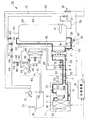
図1は、本発明に係るヒートポンプ式給湯装置における第1の実施の形態を示し、給湯タンク内の水を加熱し湯を貯溜するときの回路図である。
【0020】
この図1に示すように、ヒートポンプ式給湯装置10は、ヒートポンプユニット11、給湯ユニット12、蛇口13、浴槽14及び制御装置15を有して構成され、この制御装置15が、ヒートポンプユニット11及び給湯ユニット12を制御する。
【0021】
ヒートポンプユニット11は、圧縮機16、アキュムレータ17及びヒートポンプ熱交換器18が冷媒配管19に順次配設されて、冷媒回路の一部を構成する。冷媒配管19における圧縮機16の吐出側端部は、ユニット間配管20のガス管21に接続される。また、冷媒配管19におけるヒートポンプ熱交換器18側端部は、ユニット間配管20の液管22に接続される。
【0022】
冷媒配管19は、圧縮機16の吐出側とヒートポンプ熱交換器18側とが、電磁弁23を備えたバイパス配管24にて接続されて、吐出冷媒の過剰な高圧が逃がされる。また、ヒートポンプ熱交換器18の近傍には送風ファン25が設置されて、ヒートポンプ熱交換器18へ送風がなされる。
【0023】
前記給湯ユニット12は、給湯タンク26、給湯用熱交換器27及び浴槽用熱交換器28を備える。
【0024】
給湯用熱交換器27は、第1切換弁31を備えた冷媒配管29に配設される。この冷媒配管29における第1切換弁31側端部が、ガス側ジョイント30を介してユニット間配管20のガス管21に接続される。また、冷媒配管29における他端部が、液側ジョイント33を介してユニット間配管20の液管22に接続される。これにより、給湯用熱交換器27は、ヒートポンプユニット11の冷媒回路の一部と連結されて、図1の太線Lに示すように、冷媒が循環する冷媒回路が構成される。
【0025】
この給湯用熱交換器27と上記給湯タンク26とは、給湯用循環ポンプ34及び流量調整弁35を備えた給湯用配管36によりループ状に連結されて、図1の太線Mに示す給湯用循環回路52が構成される。
【0026】
給湯タンク26の底部には減圧逆止弁37を配設した第1水道水配管38が接続されて、給湯タンク26内へ常に水道水が供給可能とされる。つまり、給湯タンク26内に常時水道水圧が作用する。また、給湯タンク26の天部には、出湯用電磁弁39を備えた出湯配管40が接続されている。
【0027】
給湯用循環ポンプ34の稼働により給湯タンク26の底部の水が給湯用熱交換器27に送給されると、この給湯用熱交換器27は、送給された水を、ヒートポンプユニット11の圧縮機16から吐出された冷媒ガスの熱によって加熱する。この加熱された水(湯)は、流量調整弁35を経て給湯タンク26の天部へ導かれ、給湯タンク26内に例えば約60℃の湯が貯溜可能とされる。
【0028】
給湯タンク26内には電気ヒータ41が配設される。この電気ヒータ41は、給湯タンク26内の湯温を、例えば約80℃に昇温させるものである。また、給湯用配管36には、給湯用循環ポンプ34の上流側にドレンコック42が配設されて、給湯用配管36及び給湯タンク26内の湯又は水をドレンパン43を介して排水可能とする。更に、給湯用配管36には、給湯タンク26の上流側にリリーフ手段44が配設されて、給湯用熱交換器27による水の過剰加熱時における圧力が解放可能に設けられる。
【0029】
前記浴槽用熱交換器28は、図4に示すように、第2切換弁32を備えた冷媒配管45に配設される。この冷媒配管45における第2切換弁32側端部が、冷媒配管29におけるガス側ジョイント30近傍のA点に接続される。また、冷媒配管45における他端部が、冷媒配管29における液側ジョイント33近傍のB点に接続される。そして、第2切換弁32と前記第1切換弁31とは、一方が開操作されたときに、他方が閉操作されるよう構成される。
【0030】
従って、第2切換弁32の開操作時に、浴槽用熱交換器28は、ヒートポンプユニット11の冷媒回路の一部と連結されて、図4の太線Nに示すように、冷媒が循環する冷媒回路が構成される。
【0031】
この浴槽用熱交換器28と前記浴槽14とが、浴槽用循環ポンプ46、フィルタ47、水位センサ48、サーミスタ49及びフロースイッチ50を備えた第1浴槽用配管51によりループ状に連結されて、図4の太線Oに示す浴槽用循環回路53が構成される。第1浴槽用配管51には、浴槽用循環ポンプ46の下流側に、浴槽用熱交換器28をバイパスし、且つバイパス電磁弁54を備えたバイパス配管55が接続されている。
【0032】
浴槽用熱交換器28は、後述の如く浴槽14に給湯がなされて浴槽14内に湯が張られた場合、浴槽用循環ポンプ46の稼働により浴槽14内の湯(または温水)を、ヒートポンプユニット11の圧縮機16から吐出された冷媒ガスの熱によって加熱し、追い焚きを実施して、浴槽14内の湯を保温する。
【0033】
ここで、水位センサ48は、第1浴槽用配管51を介して浴槽14に連通していることから、この浴槽14内の湯(水)の水位を検出する。また、サーミスタ49は、浴槽用循環回路53内を湯が循環しているとき、その湯温を検知して、浴槽14内の湯温を間接的に検出する。また、フロースイッチ50は、浴槽用循環回路53内を湯が循環していることを検出する。更に、フィルタ47は、浴槽14内に配設されたフィルタ56と共に、湯を濾過する。
【0034】
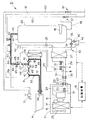
前記蛇口13は、図2に示すように、混合制御弁57及びフローセンサ58を備えた給湯配管59と出湯配管40とによって、図2の太線Pに示すように給湯タンク26に接続される。更に、この蛇口13は、減圧逆止弁61を備えた第2水道水配管60にも接続される。上記フローセンサ58は、給湯配管59内を流れる湯量を検出する。
【0035】
給湯タンク26には、第1水道水配管38を介して水道水圧が常時作用しているとこから、蛇口13の給湯栓を開くことにより、出湯配管40及び給湯配管59を経て、給湯タンク26内の湯が蛇口13に給湯される。この蛇口13からの湯は、蛇口13の水道水栓を開くことにより、第2水道水配管60からの水道水と混合されて、蛇口13から供給可能とされる。
【0036】
また、混合制御弁57は、水道水電磁弁62を備えた第3水道水配管63を介して、図2の太破線Qに示すように、第1水道水配管38の減圧逆止弁37下流側に接続される。従って、出湯用電磁弁39及び水道水電磁弁62の開弁操作時には、混合制御弁57の開度制御により、給湯タンク26及び出湯配管40からの湯と第3水道水配管63からの水道水とが混合されて、蛇口13の給湯栓から給湯される湯温が、例えば42℃に調整される。
【0037】
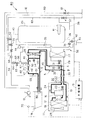
図3に示すように、給湯配管59におけるフローセンサ58の下流側と、第1浴槽用配管51における浴槽用循環ポンプ46、フロースイッチ50間とが第2浴槽用配管68により接続される。この第2浴槽用配管68には、給湯配管59の側からフローセンサ64、注湯用電磁弁65、リリーフ手段66、逆止弁67が順次配設されている。
【0038】
ここで、フローセンサ64は、第2浴槽用配管68内を流れる湯量を検出する。また、リリーフ手段66及び逆止弁67は、過剰に加熱された湯が第2浴槽用配管68内を流れた時に、その圧力を逃がすものである。
【0039】
浴槽用循環ポンプ46を停止させた状態で、注湯用電磁弁65及びバイパス電磁弁54を開操作すると、図3の太線Rに示すように、給湯タンク26内の湯が出湯配管40、給湯配管59の一部及び第2浴槽用配管68を流れて第1浴槽用配管51内に至り、この第1浴槽用配管51内で二股に分岐されて、一方がフロースイッチ50、サーミスタ49、水位センサ48及びフィルタ47を経て浴槽14へ、また、他方がバイパス配管55を経て浴槽14へそれぞれ注湯される。第1浴槽用配管51内で二方向から浴槽14内へ注湯することにより、浴槽14に湯を短時間で張ることが可能となる。
【0040】
浴槽14内に給湯タンク26から適量の湯が注湯されたことが水位センサ48により検出された段階で、注湯用電磁弁65及びバイパス電磁弁54が閉操作される。その後、浴槽14内の湯温が適温以下に低下したことがサーミスタ49により検知されたときに、浴槽用循環ポンプ46が稼働し、第2切換弁32が開操作され、ヒートポンプユニット11の圧縮機16が起動して、浴槽用循環ポンプ46の稼働により浴槽用循環回路53内を循環する湯が、浴槽用熱交換器28の冷媒熱により加熱(追い焚き)されて、浴槽14内の湯が保温される。
【0041】
このように、給湯タンク26から浴槽14へ適温の湯を適量給湯し、その後所定時間、浴槽14内の湯を浴槽用熱交換器28により適温に加熱(追い焚き)して保温する運転を、浴槽自動運転と称する。
【0042】
前記制御装置15は、ヒートポンプユニット11における圧縮機16の運転(容量制御を含む)及び停止、電磁弁23の開閉、給湯ユニット12における第1切換弁31と第2切換弁32の切換、給湯用循環ポンプ34及び浴槽用循環ポンプ46の稼働又は停止、出湯用電磁弁39、バイパス電磁弁54、水道水電磁弁62及び注湯用電磁弁65の開閉、流量調整弁35及び混合制御弁57の開度、電気ヒータ41への通電等をそれぞれ制御して、ヒートポンプユニット11及び給湯ユニット12を制御する。
【0043】
特に、制御装置15は、図1及び図4に示すように、浴槽14近傍に設置された追い焚きスイッチ70が操作された時、この追い焚きスイッチ70からの信号を入力して、ヒートポンプユニット11の圧縮機16を起動させ、給湯ユニット12の第2切換弁32を開操作させ、浴槽用循環ポンプ46を稼働させて、浴槽14内の湯(温水)を浴槽用熱交換器28へ導き、冷媒の熱により加熱(追い焚き)して、浴槽14内の湯を適温に保温する追い焚き運転を実行する。
【0044】
但し、追い焚き運転開始時には、浴槽用熱交換器28が加熱器として未だ充分に機能していず、つまり浴槽用熱交換器28内の保有水が充分に暖まっていない。
【0045】
このため、制御装置15は、追い焚きスイッチ70の操作により実行させる追い焚き運転の開始時には、ヒートポンプユニット11の圧縮機16の起動と、給湯ユニット12の第2切換弁32の開操作と、内蔵のタイマ71のカウント動作とを同時に実行させ、タイマ71のカウント値により、圧縮機16の起動から所定時間経過後に浴槽用循環ポンプ46を稼働させるよう制御する。上記所定時間は、浴槽用循環ポンプ46の稼働時には浴槽用熱交換器28が既に充分に加熱器として機能し、浴槽用熱交換器28内の保有水が充分に加熱されている時間として設定される。
【0046】
これにより、浴槽用循環ポンプ46によって浴槽用熱交換器28に導かれる浴槽14内の湯(温水)は、この浴槽用熱交換器28により直ちに充分に加熱(追い焚き)されることになる。
【0047】
従って、上記実施の形態によれば、次の効果▲1▼を奏する。
【0048】
▲1▼制御装置15が、追い焚き運転開始時に、ヒートポンプユニット11の圧縮機16を運転させてから所定時間経過後に、浴槽14と浴槽用熱交換器28との間で温水を循環可能とする浴槽用循環ポンプ46を稼働させるよう構成されたことから、浴槽用熱交換器28が加熱器として充分機能した段階で、浴槽用循環ポンプ46により浴槽14内の湯を浴槽用熱交換器28へ導くので、追い焚き運転開始時に、浴槽用熱交換器28により加熱されない湯が浴槽14内に還流することを確実に防止でき、追い焚き運転を良好に実施できる。
【0049】
〔B〕第2の実施の形態(図5)
図5は、本発明に係るヒートポンプ式給湯装置の第2の実施の形態を示す系統図である。この第2の実施の形態において、前記第1の実施の形態と同様な部分は、同一の符号を付すことにより説明を省略する。
【0050】
この第2の実施の形態のヒートポンプ式給湯装置80では、追い焚き運転開始時における制御装置15の制御が、前記第1の実施の形態と異なる。
【0051】
つまり、制御装置15は、追い焚きスイッチ70の操作により実行させる追い焚き運転の開始時には、ヒートポンプユニット11の圧縮機16を起動させ、給湯ユニット12の第2切換弁32を開操作させ、浴槽用循環ポンプ46を稼働させると同時に、浴槽用熱交換器28をバイパスするバイパス配管55のバイパス電磁弁54を開弁させて、浴槽14内の湯(温水)をバイパス配管55を経て浴槽14へ還流させる。そして、制御装置15は、追い焚きスイッチ70の操作から所定時間経過後に、バイパス電磁弁54を閉弁して、浴槽14内の湯(温水)を浴槽用熱交換器28へ導き加熱(追い焚き)して浴槽14内へ還流させる。
【0052】
上記所定時間は、バイパス電磁弁54の閉弁時には浴槽用熱交換器28が既に充分に加熱器として機能し、浴槽用熱交換器28内の保有水が充分に加熱されている時間として設定される。
【0053】
バイパス配管55の配管長が浴槽用熱交換器28の配管長よりも格段に短いことから、浴槽用循環ポンプ46の稼働によって浴槽14内へ還流される、浴槽用熱交換器28により加熱されない湯(温水)の量を低減できると共に、浴槽14内の湯(温水)がバイパス配管55を流れて浴槽用熱交換器28に流入しない間に、浴槽用熱交換器28が冷媒の熱により急速に暖まり、浴槽用熱交換器28が短時間に加熱器として機能することになる。
【0054】
従って、上記実施の形態によれば、次の効果▲2▼及び▲3▼を奏する。
【0055】
▲2▼制御装置15が、追い焚き運転開始時には、浴槽14内の湯(温水)が浴槽用熱交換器28をバイパスするバイパス配管55内に流れ、配管長の長い浴槽用熱交換器28内に流れないことから、追い焚き運転開始時に、浴槽用熱交換器28により加熱されない湯(温水)が大量に浴槽14に還流することを防止できると共に、浴槽用熱交換器28の温度を急激に上昇させることができる。これらの結果、追い焚き運転の立ち上がりの安定性を向上させることができる。
【0056】
▲3▼使用者が追い焚きスイッチ70を操作すると、制御装置15の制御により浴槽14内の湯(温水)が直ちにバイパス配管55内を流れて浴槽14内へ還流するので、追い焚きスイッチ70が操作されてから浴槽用熱交換器28の温度上昇を待って追い焚き運転を実行する場合に発生する、追い焚きスイッチ70の操作から追い焚き運転実行までの空白時間が無く、追い焚きスイッチ70が必要以上操作されたり、ヒートポンプ式給湯装置80が故障であると判断される事態を未然に防止できる。
【0057】
以上、本発明を上記実施の形態に基づいて説明したが、本発明はこれに限定されるものではない。
【0058】
例えば、追い焚き運転開始時に、ヒートポンプユニットの圧縮機を運転させてから、浴槽用熱交換器内の保有水の温度が所定温度以上となったことが温度検出器によって確認された後に、浴槽用循環ポンプを稼働させてもよい。
【0059】
また、追い焚き運転開始時に、浴槽用熱交換器をバイパスするバイパス配管に浴槽内の湯を導いて浴槽内へ還流させ、上記浴槽用熱交換器内の保有水の温度が所定温度以上となったことが温度検出器によって確認された後に、浴槽内の湯を浴槽用熱交換器に導いて加熱し浴槽内へ還流させるよう構成してもよい。
【0060】
【発明の効果】
以上のように、請求項1に記載の発明によれば、圧縮機及びヒートポンプ熱交換器を備えてなる冷媒回路の一部と、給湯タンク、給湯用熱交換器及び浴槽用熱交換器と、を備え、上記給湯用熱交換器が、上記冷媒回路の一部と連結可能に設けられて冷媒回路を構成し、冷媒熱により水を加熱して上記給湯タンクへ湯を貯溜可能とし、また、上記給湯タンクから蛇口及び浴槽へ湯を供給可能とし、更に、上記浴槽用熱交換器が、上記冷媒回路の一部と連結可能に設けられて冷媒回路を構成し、冷媒熱により上記浴槽内の湯を加熱して保温可能とするヒートポンプ式給湯装置の運転方法において、追い焚き運転開始時に、上記圧縮機を運転させてから所定時間経過後に、上記浴槽と上記浴槽用熱交換器との間で温水を循環可能とする浴槽用循環ポンプを稼働させることから、追い焚き運転開始時に、浴槽用熱交換器により加熱されない湯が浴槽内に還流することを確実に防止できる。
【0061】
請求項2に記載の発明によれば、圧縮機及びヒートポンプ熱交換器を備えてなる冷媒回路の一部と、給湯タンク、給湯用熱交換器及び浴槽用熱交換器と、を備え、上記給湯用熱交換器が、上記冷媒回路の一部と連結可能に設けられて冷媒回路を構成し、冷媒熱により水を加熱して上記給湯タンクへ湯を貯溜可能とし、また、上記給湯タンクから蛇口及び浴槽へ湯を供給可能とし、更に、上記浴槽用熱交換器が、上記冷媒回路の一部と連結可能に設けられて冷媒回路を構成し、冷媒熱により上記浴槽内の湯を加熱して保温可能とするヒートポンプ式給湯装置の運転方法において、追い焚きスイッチの操作により実行させる追い焚き運転開始時に、使用者に追い焚き運転開始を認識させるために、上記浴槽用熱交換器をバイパスするバイパス配管に浴槽内の湯を導いて上記浴槽内へ還流させ、所定時間経過後に、上記浴槽内の湯を追い焚きするために、上記浴槽内の湯を上記浴槽用熱交換器に導いて加熱し上記浴槽内へ還流させることから、追い焚き運転開始時に、浴槽用熱交換器により加熱されない湯が浴槽内に大量に還流することを防止できる。
【0062】
請求項3に記載の発明によれば、圧縮機及びヒートポンプ熱交換器を備えてなる冷媒回路の一部と、給湯タンク、給湯用熱交換器及び浴槽用熱交換器と、を備え、上記給湯用熱交換器が、上記冷媒回路の一部と連結可能に設けられて冷媒回路を構成し、冷媒熱により水を加熱して上記給湯タンクへ湯を貯溜可能とし、また、上記給湯タンクから蛇口及び浴槽へ湯を供給可能とし、更に、上記浴槽用熱交換器が、上記冷媒回路の一部と連結可能に設けられて冷媒回路を構成し、冷媒熱により上記浴槽内の湯を加熱して保温可能とするヒートポンプ式給湯装置の運転方法において、追い焚き運転開始時に、上記圧縮機を運転させてから、上記浴槽用熱交換器内の保有水の温度が所定温度以上となった後に、上記浴槽と上記浴槽用熱交換器との間で温水を循環可能とする浴槽用循環ポンプを稼働させることから、追い焚き運転開始時に、浴槽熱交換器により加熱されない湯が浴槽内に還流することを確実に防止できる。
【0063】
請求項4に記載の発明によれば、圧縮機及びヒートポンプ熱交換器を備えてなる冷媒回路の一部と、給湯タンク、給湯用熱交換器及び浴槽用熱交換器と、を備え、上記給湯用熱交換器が、上記冷媒回路の一部と連結可能に設けられて冷媒回路を構成し、冷媒熱により水を加熱して上記給湯タンクへ湯を貯溜可能とし、また、上記給湯タンクから蛇口及び浴槽へ湯を供給可能とし、更に、上記浴槽用熱交換器が、上記冷媒回路の一部と連結可能に設けられて冷媒回路を構成し、冷媒熱により上記浴槽内の湯を加熱して保温可能とするヒートポンプ式給湯装置の運転方法において、追い焚きスイッチの操作により実行させる追い焚き運転開始時に、使用者に追い焚き運転開始を認識させるために、上記浴槽用熱交換器をバイパスするバイパス配管に浴槽内の湯を導いて上記浴槽内へ還流させ、上記浴槽用熱交換器内の保有水の温度が所定温度以上となった後に、上記浴槽内の湯を追い焚きするために、上記浴槽内の湯を上記浴槽用熱交換器に導いて加熱し上記浴槽内へ還流させることから、追い焚き運転開始時に、浴槽用熱交換器により加熱されない湯が浴槽内に大量に還流することを防止できる。
【0064】
請求項5に記載の発明によれば、圧縮機及びヒートポンプ熱交換器を備えてなる冷媒回路の一部と、給湯タンク、給湯用熱交換器及び浴槽用熱交換器と、を備え、上記給湯用熱交換器が、上記冷媒回路の一部と連結可能に設けられて冷媒回路を構成し、冷媒熱により水を加熱して上記給湯タンクへ湯を貯溜可能とし、また、上記給湯タンクから蛇口及び浴槽へ湯を供給可能とし、更に、上記浴槽用熱交換器が、上記冷媒回路の一部と連結可能に設けられて冷媒回路を構成し、冷媒熱により上記浴槽内の湯を加熱して保温可能とするヒートポンプ式給湯装置において、追い焚き運転開始時に、上記圧縮機を運転させてから所定時間経過後に、上記浴槽と上記浴槽用熱交換器との間で温水を循環可能とする浴槽用循環ポンプを稼働させるよう構成されたことから、追い焚き運転開始時に、浴槽用熱交換器により加熱されない湯が浴槽内に還流することを確実に防止できる。
【0065】
請求項6に記載の発明によれば、圧縮機及びヒートポンプ熱交換器を備えてなる冷媒回路の一部と、給湯タンク、給湯用熱交換器及び浴槽用熱交換器と、を備え、上記給湯用熱交換器が、上記冷媒回路の一部と連結可能に設けられて冷媒回路を構成し、冷媒熱により水を加熱して上記給湯タンクへ湯を貯溜可能とし、また、上記給湯タンクから蛇口及び浴槽へ湯を供給可能とし、更に、上記浴槽用熱交換器が、上記冷媒回路の一部と連結可能に設けられて冷媒回路を構成し、冷媒熱により上記浴槽内の湯を加熱して保温可能とするヒートポンプ式給湯装置において、追い焚きスイッチの操作により実行させる追い焚き運転開始時に、使用者に追い焚き運転開始を認識させるために、上記浴槽用熱交換器をバイパスするバイパス配管に浴槽内の湯を導いて上記浴槽内へ還流させ、所定時間経過後に、上記浴槽内の湯を追い焚きするために、上記浴槽内の湯を上記浴槽用熱交換器に導いて加熱し上記浴槽内へ還流させるよう構成されたことから、追い焚き運転開始時に、浴槽用熱交換器により加熱されない湯が浴槽内に大量に還流することを防止できる。
【0066】
請求項7に記載の発明によれば、圧縮機及びヒートポンプ熱交換器を備えてなる冷媒回路の一部と、給湯タンク、給湯用熱交換器及び浴槽用熱交換器と、を備え、上記給湯用熱交換器が、上記冷媒回路の一部と連結可能に設けられて冷媒回路を構成し、冷媒熱により水を加熱して上記給湯タンクへ湯を貯溜可能とし、また、上記給湯タンクから蛇口及び浴槽へ湯を供給可能とし、更に、上記浴槽用熱交換器が、上記冷媒回路の一部と連結可能に設けられて冷媒回路を構成し、冷媒熱により上記浴槽内の湯を加熱して保温可能とするヒートポンプ式給湯装置において、追い焚き運転開始時に、上記圧縮機を運転させてから、上記浴槽用熱交換器内の保有水の温度が所定温度以上となった後に、上記浴槽と上記浴槽用熱交換器との間で温水を循環可能とする浴槽用循環ポンプを稼働させるよう構成されたことから、追い焚き運転開始時に、浴槽用熱交換器により加熱されない湯が浴槽内に還流することを確実に防止できる。
【0067】
請求項8に記載の発明によれば、圧縮機及びヒートポンプ熱交換器を備えてなる冷媒回路の一部と、給湯タンク、給湯用熱交換器及び浴槽用熱交換器と、を備え、上記給湯用熱交換器が、上記冷媒回路の一部と連結可能に設けられて冷媒回路を構成し、冷媒熱により水を加熱して上記給湯タンクへ湯を貯溜可能とし、また、上記給湯タンクから蛇口及び浴槽へ湯を供給可能とし、更に、上記浴槽用熱交換器が、上記冷媒回路の一部と連結可能に設けられて冷媒回路を構成し、冷媒熱により上記浴槽内の湯を加熱して保温可能とするヒートポンプ式給湯装置において、追い焚きスイッチの操作により実行させる追い焚き運転開始時に、使用者に追い焚き運転開始を認識させるために、上記浴槽用熱交換器をバイパスするバイパス配管に浴槽内の湯を導いて上記浴槽内へ還流させ、上記浴槽用熱交換器内の保有水の温度が所定温度以上となった後に、上記浴槽内の湯を追い焚きするために、上記浴槽内の湯を上記浴槽用熱交換器に導いて加熱し上記浴槽内へ還流させるよう構成されたことから、追い焚き運転開始時に、浴槽用熱交換器により加熱されない湯が浴槽内に還流することを確実に防止できる。
【図面の簡単な説明】
【図1】本発明に係るヒートポンプ式給湯装置における第1の実施の形態を示し、給湯タンク内の水を加熱し、湯を貯溜するときの回路図である。
【図2】図1のヒートポンプ式給湯装置において、蛇口から給湯するときの回路図である。
【図3】図1のヒートポンプ式給湯装置において、浴槽へ給湯するときの回路図である。
【図4】図1のヒートポンプ式給湯装置において、浴槽内の湯を加熱(追い焚き)して保温するときの回路図である。
【図5】本発明に係るヒートポンプ式給湯装置の第2の実施の形態を示す系統図である。
【符号の説明】
10 ヒートポンプ式給湯装置
11 ヒートポンプユニット
12 給湯ユニット
13 蛇口
14 浴槽
15 制御装置
16 圧縮機
18 ヒートポンプ熱交換器
26 給湯タンク
27 給湯用熱交換器
28 浴槽用熱交換器
46 浴槽用循環ポンプ
55 バイパス配管
70 追い焚きスイッチ
71 タイマ
80 ヒートポンプ式給湯装置[0001]
BACKGROUND OF THE INVENTION
The present invention relates to a heat pump type hot water supply apparatus that can supply hot water by heating water with the heat of a refrigerant, and can keep hot water by heating (chasing) hot water in a bathtub with the heat of the refrigerant.
[0002]
[Prior art]
In a conventional hot water supply device, water is heated by a heat exchanger for hot water supply through a heat exchanger for hot water to store hot water in a hot water supply tank, and this hot water can be supplied to a faucet and a bathtub. There has been proposed a heat pump type hot water supply apparatus having a function of heating (chasing) through a heat exchanger for bathtubs with heat of a refrigerant and keeping it at an appropriate temperature.
[0003]
[Problems to be solved by the invention]
As described above, the reheating operation of the hot water in the bathtub (hot water) is performed using the bathtub heat exchanger. However, at the start of the reheating operation, the heat exchanger for the bathtub does not sufficiently function as a heater, and the retained water is not warmed. Therefore, the hot water flowing through the heat exchanger for the bathtub is heated (reheating). It is not recirculated and is returned to the bathtub in a cold state. The amount of warm water that is not heated and recirculates into the bathtub increases because the length of the heat exchanger for the bathtub is long.
[0004]
The object of the present invention has been made in consideration of the above-described circumstances, and is an operation of a heat pump type hot water supply apparatus that can prevent hot water not heated by the bathtub heat exchanger from flowing back into the bathtub at the start of the reheating operation. It is in providing a method and a heat pump type hot water supply apparatus.
[0005]
[Means for Solving the Problems]
The invention described in claim 1 includes a part of a refrigerant circuit including a compressor and a heat pump heat exchanger, a hot water tank, a hot water heat exchanger, and a bathtub heat exchanger, and the heat for hot water supply. An exchanger is provided so as to be connectable to a part of the refrigerant circuit, constitutes a refrigerant circuit, heats water with refrigerant heat, and can store hot water in the hot water tank, and the faucet and bathtub from the hot water tank. It is possible to supply hot water, and the heat exchanger for the bathtub is connected to a part of the refrigerant circuit to form a refrigerant circuit, and the hot water in the bathtub can be heated by the refrigerant heat to be kept warm. In the operation method of the heat pump type hot water supply apparatus, the hot water can be circulated between the bathtub and the bathtub heat exchanger after a predetermined time has elapsed since the compressor was operated at the start of the reheating operation. Operating circulation pump It is an feature.
[0006]
The invention described in claim 2 includes a part of a refrigerant circuit including a compressor and a heat pump heat exchanger, a hot water supply tank, a hot water heat exchanger, and a bathtub heat exchanger, and the heat for hot water supply. An exchanger is provided so as to be connectable to a part of the refrigerant circuit, constitutes a refrigerant circuit, heats water with refrigerant heat, and can store hot water in the hot water tank, and the faucet and bathtub from the hot water tank. It is possible to supply hot water, and the heat exchanger for the bathtub is connected to a part of the refrigerant circuit to form a refrigerant circuit, and the hot water in the bathtub can be heated by the refrigerant heat to be kept warm. In the operation method of the heat pump type hot water supply apparatus, It is executed by operating the tracking switch At the start of chasing operation, In order to make the user recognize the start of driving The hot water in the bathtub is led to a bypass pipe that bypasses the heat exchanger for the bathtub and is refluxed into the bathtub. In order to chase the hot water in the above bathtub, The hot water in the bath is guided to the heat exchanger for the bath and heated to be refluxed into the bath.
[0007]
The invention according to claim 3 comprises a part of a refrigerant circuit comprising a compressor and a heat pump heat exchanger, a hot water tank, a hot water heat exchanger, and a bathtub heat exchanger, An exchanger is provided so as to be connectable to a part of the refrigerant circuit, constitutes a refrigerant circuit, heats water with refrigerant heat, and can store hot water in the hot water tank, and the faucet and bathtub from the hot water tank. It is possible to supply hot water, and the heat exchanger for the bathtub is connected to a part of the refrigerant circuit to form a refrigerant circuit, and the hot water in the bathtub can be heated by the refrigerant heat to be kept warm. In the operation method of the heat pump type hot water supply apparatus, after starting the reheating operation, after operating the compressor, the temperature of the retained water in the heat exchanger for the bathtub becomes a predetermined temperature or higher, Hot water between the heat exchanger for bathtubs It is characterized in that operating the bath circulation pump to the ring possible.
[0008]
The invention described in claim 4 comprises a part of a refrigerant circuit comprising a compressor and a heat pump heat exchanger, a hot water supply tank, a hot water supply heat exchanger, and a bathtub heat exchanger, and the hot water supply heat described above. An exchanger is provided so as to be connectable to a part of the refrigerant circuit, constitutes a refrigerant circuit, heats water with refrigerant heat, and can store hot water in the hot water tank, and the faucet and bathtub from the hot water tank. It is possible to supply hot water, and the heat exchanger for the bathtub is connected to a part of the refrigerant circuit to form a refrigerant circuit, and the hot water in the bathtub can be heated by the refrigerant heat to be kept warm. In the operation method of the heat pump type hot water supply apparatus, It is executed by operating the tracking switch At the start of chasing operation, In order to make the user recognize the start of driving After the hot water in the bathtub is led to the bypass pipe that bypasses the heat exchanger for the bathtub and refluxed into the bathtub, the temperature of the retained water in the bathtub heat exchanger becomes a predetermined temperature or higher, In order to chase the hot water in the above bathtub, The hot water in the bathtub is led to the heat exchanger for the bathtub and heated to be refluxed into the bathtub. Ah The
[0009]
The invention according to claim 5 comprises a part of a refrigerant circuit comprising a compressor and a heat pump heat exchanger, a hot water supply tank, a hot water heat exchanger, and a bathtub heat exchanger, An exchanger is provided so as to be connectable to a part of the refrigerant circuit, constitutes a refrigerant circuit, heats water with refrigerant heat, and can store hot water in the hot water tank, and the faucet and bathtub from the hot water tank. It is possible to supply hot water, and the heat exchanger for the bathtub is connected to a part of the refrigerant circuit to form a refrigerant circuit, and the hot water in the bathtub can be heated by the refrigerant heat to be kept warm. In the heat pump type hot water supply apparatus, a hot water circulation device for a bathtub that allows hot water to circulate between the bathtub and the heat exchanger for the bathtub after a predetermined time has elapsed since the compressor was operated at the start of the reheating operation Configured to run And it is characterized in and.
[0010]
The invention described in claim 6 comprises a part of a refrigerant circuit comprising a compressor and a heat pump heat exchanger, a hot water supply tank, a hot water supply heat exchanger, and a bathtub heat exchanger, An exchanger is provided so as to be connectable to a part of the refrigerant circuit, constitutes a refrigerant circuit, heats water with refrigerant heat, and can store hot water in the hot water tank, and the faucet and bathtub from the hot water tank. It is possible to supply hot water, and the heat exchanger for the bathtub is connected to a part of the refrigerant circuit to form a refrigerant circuit, and the hot water in the bathtub can be heated by the refrigerant heat to be kept warm. In the heat pump hot water supply device It is executed by operating the tracking switch At the start of chasing operation, In order to make the user recognize the start of driving The hot water in the bathtub is led to a bypass pipe that bypasses the heat exchanger for the bathtub and is refluxed into the bathtub. In order to chase the hot water in the above bathtub, The hot water in the bathtub is guided to the heat exchanger for the bathtub and heated to be recirculated into the bathtub.
[0011]
The invention described in claim 7 includes a part of a refrigerant circuit including a compressor and a heat pump heat exchanger, a hot water supply tank, a hot water supply heat exchanger, and a bathtub heat exchanger, and the hot water supply heat described above. An exchanger is provided so as to be connectable to a part of the refrigerant circuit, constitutes a refrigerant circuit, heats water with refrigerant heat, and can store hot water in the hot water tank, and the faucet and bathtub from the hot water tank. It is possible to supply hot water, and the heat exchanger for the bathtub is connected to a part of the refrigerant circuit to form a refrigerant circuit, and the hot water in the bathtub can be heated by the refrigerant heat to be kept warm. In the heat pump hot water supply apparatus, when the reheating operation is started, the compressor is operated, and after the temperature of the retained water in the heat exchanger for the bath becomes a predetermined temperature or higher, the bath and the bath Hot water can be circulated with the heat exchanger It is characterized in that it has been configured to run a bath circulation pump that.
[0012]
The invention described in claim 8 includes a part of a refrigerant circuit including a compressor and a heat pump heat exchanger, a hot water supply tank, a hot water heat exchanger, and a bathtub heat exchanger, and the heat for hot water supply. An exchanger is provided so as to be connectable to a part of the refrigerant circuit, constitutes a refrigerant circuit, heats water with refrigerant heat, and can store hot water in the hot water tank, and the faucet and bathtub from the hot water tank. It is possible to supply hot water, and the heat exchanger for the bathtub is connected to a part of the refrigerant circuit to form a refrigerant circuit, and the hot water in the bathtub can be heated by the refrigerant heat to be kept warm. In the heat pump hot water supply device It is executed by operating the tracking switch At the start of chasing operation, In order to make the user recognize the start of driving After the hot water in the bathtub is led to the bypass pipe that bypasses the heat exchanger for the bathtub and refluxed into the bathtub, the temperature of the retained water in the bathtub heat exchanger becomes a predetermined temperature or higher, In order to chase the hot water in the above bathtub, The hot water in the bathtub is guided to the heat exchanger for the bathtub and heated to be recirculated into the bathtub.
[0013]
The invention according to claim 1, 3, 5 or 7 has the following effects.
[0014]
At the start of reheating operation, after a predetermined time has elapsed since the compressor of the heat pump unit was operated, or after the temperature of the retained water in the heat exchanger for the bathtub has exceeded the predetermined temperature, the heat exchanger for the bathtub and the bathtub The hot water in the bathtub is removed by the bathtub circulation pump when the bathtub heat exchanger functions sufficiently as a heater. Since it guides to the heat exchanger for heat | fever, it can prevent reliably that the hot water which is not heated by the heat exchanger for bathtubs recirculate | refluxs in a bathtub at the time of a reheating operation, and can perform a reheating operation favorably.
[0015]
The invention according to claim 2, 4, 6 or 8 has the following action.
[0016]
At the start of reheating operation, hot water in the bathtub flows into the bypass pipe that bypasses the heat exchanger for bathtubs and does not flow into the heat exchanger for long bathtubs. While preventing a large amount of hot water not heated by the bathtub heat exchanger from flowing back into the bathtub, the temperature of the bathtub heat exchanger can be rapidly increased. As a result, it is possible to improve the stability at the start of the chasing operation.
[0017]
Also, when the user operates the reheating switch, the hot water in the bathtub immediately flows through the bypass pipe and returns to the bathtub, so that the temperature of the heat exchanger for the bathtub rises after the reheating switch is operated. When there is no blank time from the operation of the refueling switch to the execution of the retirement operation, which occurs when the recurring operation is executed after waiting for Can be prevented.
[0018]
DETAILED DESCRIPTION OF THE INVENTION
Hereinafter, embodiments of the present invention will be described with reference to the drawings.
[0019]
[A] First embodiment (FIGS. 1 to 4)
FIG. 1 shows a first embodiment of a heat pump hot water supply apparatus according to the present invention, and is a circuit diagram when water in a hot water supply tank is heated and hot water is stored.
[0020]
As shown in FIG. 1, the heat pump hot
[0021]
In the
[0022]
In the
[0023]
The hot
[0024]
The hot water
[0025]
The hot water
[0026]
A first
[0027]
When the water at the bottom of the hot
[0028]
An
[0029]
As shown in FIG. 4, the
[0030]
Therefore, at the time of opening the
[0031]
The
[0032]
The
[0033]
Here, since the
[0034]
As shown in FIG. 2, the
[0035]
Since the tap water pressure is always applied to the hot
[0036]
In addition, the mixing
[0037]
As shown in FIG. 3, the
[0038]
Here, the
[0039]
When the hot
[0040]
When the
[0041]
In this manner, an operation of supplying an appropriate amount of hot water from the hot
[0042]
The
[0043]
In particular, as shown in FIGS. 1 and 4, the
[0044]
However, at the start of the reheating operation, the
[0045]
Therefore, the
[0046]
As a result, the hot water (hot water) in the
[0047]
Therefore, according to the above embodiment, the following effect (1) is achieved.
[0048]
(1) When the
[0049]
[B] Second embodiment (FIG. 5)
FIG. 5 is a system diagram showing a second embodiment of the heat pump hot water supply apparatus according to the present invention. In the second embodiment, the same parts as those in the first embodiment are denoted by the same reference numerals, and the description thereof is omitted.
[0050]
In the heat pump hot
[0051]
In other words, the
[0052]
The predetermined time is set as a time during which the
[0053]
Since the pipe length of the
[0054]
Therefore, according to the above embodiment, the following effects (2) and (3) are achieved.
[0055]
(2) When the
[0056]
(3) When the user operates the reheating
[0057]
As mentioned above, although this invention was demonstrated based on the said embodiment, this invention is not limited to this.
[0058]
For example, at the start of the reheating operation, after the compressor of the heat pump unit is operated, the temperature detector confirms that the temperature of the retained water in the heat exchanger for the bathtub is equal to or higher than the predetermined temperature. A circulation pump may be operated.
[0059]
Also, at the start of the reheating operation, hot water in the bathtub is led to the bypass pipe that bypasses the heat exchanger for the bathtub and returned to the bathtub, so that the temperature of the retained water in the bathtub heat exchanger becomes a predetermined temperature or higher. After the fact is confirmed by the temperature detector, the hot water in the bathtub may be guided to the heat exchanger for the bathtub and heated to be refluxed into the bathtub.
[0060]
【The invention's effect】
As described above, according to the invention described in claim 1, a part of the refrigerant circuit including the compressor and the heat pump heat exchanger, the hot water tank, the hot water heat exchanger, and the bathtub heat exchanger, The hot water supply heat exchanger is provided so as to be connectable to a part of the refrigerant circuit, constitutes a refrigerant circuit, heats water with the refrigerant heat, and can store hot water in the hot water tank, Hot water can be supplied from the hot water supply tank to the faucet and the bathtub, and further, the bathtub heat exchanger is provided so as to be connectable to a part of the refrigerant circuit to constitute a refrigerant circuit. In the operation method of the heat pump type hot water supply apparatus that enables hot water to be kept warm, at the start of the reheating operation, after a predetermined time has elapsed since the compressor was operated, between the bathtub and the heat exchanger for the bathtub Bathtub circulation port that allows hot water to circulate From the fact that to run the flop, chase 焚 It is possible to reliably prevent hot water not heated by the bathtub heat exchanger from flowing back into the bathtub at the start of the operation.
[0061]
According to invention of Claim 2, it comprises a part of refrigerant circuit provided with a compressor and a heat pump heat exchanger, and a hot water supply tank, the hot water heat exchanger, and the heat exchanger for bathtubs, The said hot water supply A heat exchanger for connecting to a part of the refrigerant circuit to form a refrigerant circuit, heating water with the refrigerant heat to store hot water in the hot water tank, and faucet from the hot water tank Hot water can be supplied to the bathtub, and the bathtub heat exchanger is connected to a part of the refrigerant circuit to form a refrigerant circuit, and the hot water in the bathtub is heated by the refrigerant heat. In the operation method of the heat pump type hot water supply device that enables heat insulation, It is executed by operating the tracking switch At the start of chasing operation, In order to make the user recognize the start of driving The hot water in the bathtub is led to a bypass pipe that bypasses the heat exchanger for the bathtub and is refluxed into the bathtub. In order to chase the hot water in the above bathtub, The hot water in the bathtub is led to the heat exchanger for the bathtub and heated to be refluxed into the bathtub. 焚 It is possible to prevent a large amount of hot water not heated by the bathtub heat exchanger from flowing back into the bathtub at the start of the operation.
[0062]
According to a third aspect of the present invention, the apparatus includes a part of a refrigerant circuit including a compressor and a heat pump heat exchanger, and a hot water supply tank, a hot water supply heat exchanger, and a bathtub heat exchanger. A heat exchanger for connecting to a part of the refrigerant circuit to form a refrigerant circuit, heating water with the refrigerant heat to store hot water in the hot water tank, and faucet from the hot water tank Hot water can be supplied to the bathtub, and the bathtub heat exchanger is connected to a part of the refrigerant circuit to form a refrigerant circuit, and the hot water in the bathtub is heated by the refrigerant heat. In the operation method of the heat pump type hot water supply apparatus that enables heat retention, at the start of the reheating operation, after the compressor is operated, the temperature of the retained water in the heat exchanger for the bathtub becomes equal to or higher than the predetermined temperature, Between the bathtub and the above-mentioned heat exchanger for bathtub The bath circulation pump to allow the circulation of water from be operated, Bath 焚 It is possible to reliably prevent hot water that is not heated by the bathtub heat exchanger from flowing back into the bathtub at the start of the operation.
[0063]
According to invention of Claim 4, it comprises a part of refrigerant circuit provided with a compressor and a heat pump heat exchanger, and a hot water supply tank, the hot water heat exchanger, and the heat exchanger for bathtubs, The said hot water supply A heat exchanger for connecting to a part of the refrigerant circuit to form a refrigerant circuit, heating water with the refrigerant heat to store hot water in the hot water tank, and faucet from the hot water tank Hot water can be supplied to the bathtub, and the bathtub heat exchanger is connected to a part of the refrigerant circuit to form a refrigerant circuit, and the hot water in the bathtub is heated by the refrigerant heat. In the operation method of the heat pump type hot water supply device that enables heat insulation, It is executed by operating the tracking switch At the start of chasing operation, In order to make the user recognize the start of driving After the hot water in the bathtub is led to the bypass pipe that bypasses the heat exchanger for the bathtub and refluxed into the bathtub, the temperature of the retained water in the bathtub heat exchanger becomes a predetermined temperature or higher, In order to chase the hot water in the above bathtub, The hot water in the bathtub is led to the heat exchanger for the bathtub and heated to be refluxed into the bathtub. 焚 It is possible to prevent a large amount of hot water not heated by the bathtub heat exchanger from flowing back into the bathtub at the start of the operation.
[0064]
According to the invention described in claim 5, a part of a refrigerant circuit comprising a compressor and a heat pump heat exchanger, a hot water tank, a hot water heat exchanger, and a bathtub heat exchanger, A heat exchanger for connecting to a part of the refrigerant circuit to form a refrigerant circuit, heating water with the refrigerant heat to store hot water in the hot water tank, and faucet from the hot water tank Hot water can be supplied to the bathtub, and the bathtub heat exchanger is connected to a part of the refrigerant circuit to form a refrigerant circuit, and the hot water in the bathtub is heated by the refrigerant heat. In a heat pump type hot water supply apparatus capable of keeping warm, at the start of reheating operation, after a predetermined time has elapsed since the compressor was operated, hot water can be circulated between the bathtub and the bathtub heat exchanger. Configured to operate the circulation pump From what has been, chase 焚 It is possible to reliably prevent hot water not heated by the bathtub heat exchanger from flowing back into the bathtub at the start of the operation.
[0065]
According to invention of Claim 6, it comprises a part of refrigerant circuit provided with a compressor and a heat pump heat exchanger, and a hot water supply tank, the hot water heat exchanger, and the heat exchanger for bathtubs, The said hot water supply A heat exchanger for connecting to a part of the refrigerant circuit to form a refrigerant circuit, heating water with the refrigerant heat to store hot water in the hot water tank, and faucet from the hot water tank Hot water can be supplied to the bathtub, and the bathtub heat exchanger is connected to a part of the refrigerant circuit to form a refrigerant circuit, and the hot water in the bathtub is heated by the refrigerant heat. In a heat pump type hot water supply device that can keep warm, It is executed by operating the tracking switch At the start of chasing operation, In order to make the user recognize the start of driving The hot water in the bathtub is led to a bypass pipe that bypasses the heat exchanger for the bathtub and is refluxed into the bathtub. In order to chase the hot water in the above bathtub, The hot water in the bathtub is guided to the heat exchanger for the bathtub and heated to be refluxed into the bathtub. 焚 It is possible to prevent a large amount of hot water not heated by the bathtub heat exchanger from flowing back into the bathtub at the start of the operation.
[0066]
According to invention of Claim 7, it comprises a part of refrigerant circuit provided with a compressor and a heat pump heat exchanger, and a hot water supply tank, the hot water heat exchanger, and the heat exchanger for bathtubs, The said hot water supply A heat exchanger for connecting to a part of the refrigerant circuit to form a refrigerant circuit, heating water with the refrigerant heat to store hot water in the hot water tank, and faucet from the hot water tank Hot water can be supplied to the bathtub, and the bathtub heat exchanger is connected to a part of the refrigerant circuit to form a refrigerant circuit, and the hot water in the bathtub is heated by the refrigerant heat. In the heat pump type hot water supply apparatus that enables heat retention, at the start of the reheating operation, after the compressor is operated, the temperature of the retained water in the heat exchanger for the bathtub becomes equal to or higher than the predetermined temperature, and then the bathtub and the above Circulates hot water with the heat exchanger for bathtubs Since configured to run the bath circulation pump to capacity, follow 焚 It is possible to reliably prevent hot water not heated by the bathtub heat exchanger from flowing back into the bathtub at the start of the operation.
[0067]
According to invention of Claim 8, it comprises a part of refrigerant circuit provided with a compressor and a heat pump heat exchanger, and a hot water supply tank, the hot water heat exchanger, and the heat exchanger for bathtubs, The said hot water supply A heat exchanger for connecting to a part of the refrigerant circuit to form a refrigerant circuit, heating water with the refrigerant heat to store hot water in the hot water tank, and faucet from the hot water tank Hot water can be supplied to the bathtub, and the bathtub heat exchanger is connected to a part of the refrigerant circuit to form a refrigerant circuit, and the hot water in the bathtub is heated by the refrigerant heat. In a heat pump type hot water supply device that can keep warm, It is executed by operating the tracking switch At the start of chasing operation, In order to make the user recognize the start of driving After the hot water in the bathtub is led to the bypass pipe that bypasses the heat exchanger for the bathtub and refluxed into the bathtub, the temperature of the retained water in the bathtub heat exchanger becomes a predetermined temperature or higher, In order to chase the hot water in the above bathtub, The hot water in the bathtub is guided to the heat exchanger for the bathtub and heated to be refluxed into the bathtub. 焚 It is possible to reliably prevent hot water not heated by the bathtub heat exchanger from flowing back into the bathtub at the start of the operation.
[Brief description of the drawings]
FIG. 1 shows a first embodiment of a heat pump hot water supply apparatus according to the present invention, and is a circuit diagram when water in a hot water supply tank is heated to store hot water.
2 is a circuit diagram when hot water is supplied from a faucet in the heat pump type hot water supply apparatus of FIG. 1;
3 is a circuit diagram when hot water is supplied to a bathtub in the heat pump type hot water supply apparatus of FIG. 1. FIG.
4 is a circuit diagram when the hot water in the bathtub is heated (chaired) to keep warm in the heat pump type hot water supply apparatus of FIG. 1. FIG.
FIG. 5 is a system diagram showing a second embodiment of the heat pump hot water supply apparatus according to the present invention.
[Explanation of symbols]
10 Heat pump water heater
11 Heat pump unit
12 Hot water supply unit
13 Faucet
14 Bathtub
15 Control device
16 Compressor
18 Heat pump heat exchanger
26 Hot water tank
27 Heat exchanger for hot water supply
28 Heat exchanger for bathtub
46 Circulation pump for bathtub
55 Bypass piping
70 Reap switch
71 timer
80 Heat pump water heater
Claims (8)
給湯タンク、給湯用熱交換器及び浴槽用熱交換器と、を備え、
上記給湯用熱交換器が、上記冷媒回路の一部と連結可能に設けられて冷媒回路を構成し、冷媒熱により水を加熱して上記給湯タンクへ湯を貯溜可能とし、また、上記給湯タンクから蛇口及び浴槽へ湯を供給可能とし、更に、上記浴槽用熱交換器が、上記冷媒回路の一部と連結可能に設けられて冷媒回路を構成し、冷媒熱により上記浴槽内の湯を加熱して保温可能とするヒートポンプ式給湯装置の運転方法において、
追い焚き運転開始時に、上記圧縮機を運転させてから所定時間経過後に、上記浴槽と上記浴槽用熱交換器との間で温水を循環可能とする浴槽用循環ポンプを稼働させることを特徴とするヒートポンプ式給湯装置の運転方法。A part of a refrigerant circuit comprising a compressor and a heat pump heat exchanger;
A hot water tank, a heat exchanger for hot water supply, and a heat exchanger for bathtubs,
The hot water supply heat exchanger is provided so as to be connectable to a part of the refrigerant circuit, constitutes a refrigerant circuit, heats water by the refrigerant heat, enables hot water to be stored in the hot water supply tank, and the hot water supply tank Hot water can be supplied to the faucet and the bathtub, and the heat exchanger for the bathtub is provided so as to be connectable to a part of the refrigerant circuit to constitute a refrigerant circuit, and the hot water in the bathtub is heated by the refrigerant heat. In the operation method of the heat pump type hot water supply device that can be kept warm,
At the start of reheating operation, after a predetermined time has elapsed since the compressor was operated, a circulation pump for a bathtub that enables circulation of hot water between the bathtub and the heat exchanger for bathtub is operated. Operation method of heat pump type hot water supply device.
給湯タンク、給湯用熱交換器及び浴槽用熱交換器と、を備え、
上記給湯用熱交換器が、上記冷媒回路の一部と連結可能に設けられて冷媒回路を構成し、冷媒熱により水を加熱して上記給湯タンクへ湯を貯溜可能とし、また、上記給湯タンクから蛇口及び浴槽へ湯を供給可能とし、更に、上記浴槽用熱交換器が、上記冷媒回路の一部と連結可能に設けられて冷媒回路を構成し、冷媒熱により上記浴槽内の湯を加熱して保温可能とするヒートポンプ式給湯装置の運転方法において、
追い焚きスイッチの操作により実行させる追い焚き運転開始時に、使用者に追い焚き運転開始を認識させるために、上記浴槽用熱交換器をバイパスするバイパス配管に浴槽内の湯を導いて上記浴槽内へ還流させ、所定時間経過後に、上記浴槽内の湯を追い焚きするために、上記浴槽内の湯を上記浴槽用熱交換器に導いて加熱し上記浴槽内へ還流させることを特徴とするヒートポンプ式給湯装置の運転方法。A part of a refrigerant circuit comprising a compressor and a heat pump heat exchanger;
A hot water tank, a heat exchanger for hot water supply, and a heat exchanger for bathtubs,
The hot water supply heat exchanger is provided so as to be connectable to a part of the refrigerant circuit, constitutes a refrigerant circuit, heats water by the refrigerant heat, enables hot water to be stored in the hot water supply tank, and the hot water supply tank Hot water can be supplied to the faucet and the bathtub, and the heat exchanger for the bathtub is provided so as to be connectable to a part of the refrigerant circuit to constitute a refrigerant circuit, and the hot water in the bathtub is heated by the refrigerant heat. In the operation method of the heat pump type hot water supply device that can be kept warm,
In order to make the user recognize the start of reheating operation when starting reheating operation to be executed by operating the reheating switch, hot water in the bathtub is led to the bypass pipe that bypasses the heat exchanger for bathtub and into the bathtub. In order to replenish the hot water in the bath after a predetermined time has passed , the hot water in the bath is led to the bath heat exchanger and heated to reflux into the bath. How to operate the water heater.
給湯タンク、給湯用熱交換器及び浴槽用熱交換器と、を備え、
上記給湯用熱交換器が、上記冷媒回路の一部と連結可能に設けられて冷媒回路を構成し、冷媒熱により水を加熱して上記給湯タンクへ湯を貯溜可能とし、また、上記給湯タンクから蛇口及び浴槽へ湯を供給可能とし、更に、上記浴槽用熱交換器が、上記冷媒回路の一部と連結可能に設けられて冷媒回路を構成し、冷媒熱により上記浴槽内の湯を加熱して保温可能とするヒートポンプ式給湯装置の運転方法において、
追い焚き運転開始時に、上記圧縮機を運転させてから、上記浴槽用熱交換器内の保有水の温度が所定温度以上となった後に、上記浴槽と上記浴槽用熱交換器との間で温水を循環可能とする浴槽用循環ポンプを稼働させることを特徴とするヒートポンプ式給湯装置の運転方法。A part of a refrigerant circuit comprising a compressor and a heat pump heat exchanger;
A hot water tank, a heat exchanger for hot water supply, and a heat exchanger for bathtubs,
The hot water supply heat exchanger is provided so as to be connectable to a part of the refrigerant circuit, constitutes a refrigerant circuit, heats water by the refrigerant heat, enables hot water to be stored in the hot water supply tank, and the hot water supply tank Hot water can be supplied to the faucet and the bathtub, and the heat exchanger for the bathtub is provided so as to be connectable to a part of the refrigerant circuit to constitute a refrigerant circuit, and the hot water in the bathtub is heated by the refrigerant heat. In the operation method of the heat pump type hot water supply device that can be kept warm,
At the start of reheating operation, after the compressor is operated, the temperature of the retained water in the bathtub heat exchanger becomes equal to or higher than a predetermined temperature, and then hot water is added between the bathtub and the bathtub heat exchanger. The operation method of the heat pump type hot water supply apparatus characterized by operating the circulation pump for bathtubs which can circulate.
給湯タンク、給湯用熱交換器及び浴槽用熱交換器と、を備え、
上記給湯用熱交換器が、上記冷媒回路の一部と連結可能に設けられて冷媒回路を構成し、冷媒熱により水を加熱して上記給湯タンクへ湯を貯溜可能とし、また、上記給湯タンクから蛇口及び浴槽へ湯を供給可能とし、更に、上記浴槽用熱交換器が、上記冷媒回路の一部と連結可能に設けられて冷媒回路を構成し、冷媒熱により上記浴槽内の湯を加熱して保温可能とするヒートポンプ式給湯装置の運転方法において、
追い焚きスイッチの操作により実行させる追い焚き運転開始時に、使用者に追い焚き運転開始を認識させるために、上記浴槽用熱交換器をバイパスするバイパス配管に浴槽内の湯を導いて上記浴槽内へ還流させ、上記浴槽用熱交換器内の保有水の温度が所定温度以上となった後に、上記浴槽内の湯を追い焚きするために、上記浴槽内の湯を上記浴槽用熱交換器に導いて加熱し上記浴槽内へ還流させることを特徴とするヒートポンプ式給湯装置の運転方法。A part of a refrigerant circuit comprising a compressor and a heat pump heat exchanger;
A hot water tank, a heat exchanger for hot water supply, and a heat exchanger for bathtubs,
The hot water supply heat exchanger is provided so as to be connectable to a part of the refrigerant circuit, constitutes a refrigerant circuit, heats water by the refrigerant heat, enables hot water to be stored in the hot water supply tank, and the hot water supply tank Hot water can be supplied to the faucet and the bathtub, and the heat exchanger for the bathtub is provided so as to be connectable to a part of the refrigerant circuit to constitute a refrigerant circuit, and the hot water in the bathtub is heated by the refrigerant heat. In the operation method of the heat pump type hot water supply device that can be kept warm,
In order to make the user recognize the start of reheating operation when starting reheating operation to be executed by operating the reheating switch, hot water in the bathtub is led to the bypass pipe that bypasses the heat exchanger for bathtub and into the bathtub. In order to recirculate the hot water in the bathtub after the temperature of the retained water in the bathtub heat exchanger becomes equal to or higher than a predetermined temperature, the hot water in the bathtub is guided to the bathtub heat exchanger. The method of operating a heat pump type hot water supply apparatus, wherein the heat pump is heated and refluxed into the bathtub.
給湯タンク、給湯用熱交換器及び浴槽用熱交換器と、を備え、
上記給湯用熱交換器が、上記冷媒回路の一部と連結可能に設けられて冷媒回路を構成し、冷媒熱により水を加熱して上記給湯タンクへ湯を貯溜可能とし、また、上記給湯タンクから蛇口及び浴槽へ湯を供給可能とし、更に、上記浴槽用熱交換器が、上記冷媒回路の一部と連結可能に設けられて冷媒回路を構成し、冷媒熱により上記浴槽内の湯を加熱して保温可能とするヒートポンプ式給湯装置において、
追い焚き運転開始時に、上記圧縮機を運転させてから所定時間経過後に、上記浴槽と上記浴槽用熱交換器との間で温水を循環可能とする浴槽用循環ポンプを稼働させるよう構成されたことを特徴とするヒートポンプ式給湯装置。A part of a refrigerant circuit comprising a compressor and a heat pump heat exchanger;
A hot water tank, a heat exchanger for hot water supply, and a heat exchanger for bathtubs,
The hot water supply heat exchanger is provided so as to be connectable to a part of the refrigerant circuit, constitutes a refrigerant circuit, heats water by the refrigerant heat, enables hot water to be stored in the hot water supply tank, and the hot water supply tank Hot water can be supplied to the faucet and the bathtub, and the heat exchanger for the bathtub is provided so as to be connectable to a part of the refrigerant circuit to constitute a refrigerant circuit, and the hot water in the bathtub is heated by the refrigerant heat. In the heat pump type hot water supply device that can be kept warm,
It was configured to operate a circulation pump for bathtubs that enables circulating hot water between the bathtub and the heat exchanger for bathtubs after a predetermined time has passed since the compressor was operated at the start of reheating operation. A heat pump type hot water supply device characterized by
給湯タンク、給湯用熱交換器及び浴槽用熱交換器と、を備え、
上記給湯用熱交換器が、上記冷媒回路の一部と連結可能に設けられて冷媒回路を構成し、冷媒熱により水を加熱して上記給湯タンクへ湯を貯溜可能とし、また、上記給湯タンクから蛇口及び浴槽へ湯を供給可能とし、更に、上記浴槽用熱交換器が、上記冷媒回路の一部と連結可能に設けられて冷媒回路を構成し、冷媒熱により上記浴槽内の湯を加熱して保温可能とするヒートポンプ式給湯装置において、
追い焚きスイッチの操作により実行させる追い焚き運転開始時に、使用者に追い焚き運転開始を認識させるために、上記浴槽用熱交換器をバイパスするバイパス配管に浴槽内の湯を導いて上記浴槽内へ還流させ、所定時間経過後に、上記浴槽内の湯を追い焚きするために、上記浴槽内の湯を上記浴槽用熱交換器に導いて加熱し上記浴槽内へ還流させるよう構成されたことを特徴とするヒートポンプ式給湯装置。A part of a refrigerant circuit comprising a compressor and a heat pump heat exchanger;
A hot water tank, a heat exchanger for hot water supply, and a heat exchanger for bathtubs,
The hot water supply heat exchanger is provided so as to be connectable to a part of the refrigerant circuit, constitutes a refrigerant circuit, heats water by the refrigerant heat, enables hot water to be stored in the hot water supply tank, and the hot water supply tank Hot water can be supplied to the faucet and the bathtub, and the heat exchanger for the bathtub is provided so as to be connectable to a part of the refrigerant circuit to constitute a refrigerant circuit, and the hot water in the bathtub is heated by the refrigerant heat. In the heat pump type hot water supply device that can be kept warm,
In order to make the user recognize the start of reheating operation when starting reheating operation to be executed by operating the reheating switch, hot water in the bathtub is led to the bypass pipe that bypasses the heat exchanger for bathtub and into the bathtub. In order to recirculate the hot water in the bathtub after a predetermined time has passed, the hot water in the bathtub is led to the heat exchanger for the bathtub and heated to be refluxed into the bathtub. Heat pump type hot water supply equipment.
給湯タンク、給湯用熱交換器及び浴槽用熱交換器と、を備え、
上記給湯用熱交換器が、上記冷媒回路の一部と連結可能に設けられて冷媒回路を構成し、冷媒熱により水を加熱して上記給湯タンクへ湯を貯溜可能とし、また、上記給湯タンクから蛇口及び浴槽へ湯を供給可能とし、更に、上記浴槽用熱交換器が、上記冷媒回路の一部と連結可能に設けられて冷媒回路を構成し、冷媒熱により上記浴槽内の湯を加熱して保温可能とするヒートポンプ式給湯装置において、
追い焚き運転開始時に、上記圧縮機を運転させてから、上記浴槽用熱交換器内の保有水の温度が所定温度以上となった後に、上記浴槽と上記浴槽用熱交換器との間で温水を循環可能とする浴槽用循環ポンプを稼働させるよう構成されたことを特徴とするヒートポンプ式給湯装置。A part of a refrigerant circuit comprising a compressor and a heat pump heat exchanger;
A hot water tank, a heat exchanger for hot water supply, and a heat exchanger for bathtubs,
The hot water supply heat exchanger is provided so as to be connectable to a part of the refrigerant circuit, constitutes a refrigerant circuit, heats water by the refrigerant heat, enables hot water to be stored in the hot water supply tank, and the hot water supply tank Hot water can be supplied to the faucet and the bathtub, and the heat exchanger for the bathtub is provided so as to be connectable to a part of the refrigerant circuit to constitute a refrigerant circuit, and the hot water in the bathtub is heated by the refrigerant heat. In the heat pump type hot water supply device that can be kept warm,
At the start of reheating operation, after the compressor is operated, the temperature of the retained water in the bathtub heat exchanger becomes equal to or higher than a predetermined temperature, and then hot water is added between the bathtub and the bathtub heat exchanger. A heat pump type hot water supply apparatus configured to operate a circulation pump for bathtubs that can circulate water.
給湯タンク、給湯用熱交換器及び浴槽用熱交換器と、を備え、
上記給湯用熱交換器が、上記冷媒回路の一部と連結可能に設けられて冷媒回路を構成し、冷媒熱により水を加熱して上記給湯タンクへ湯を貯溜可能とし、また、上記給湯タンクから蛇口及び浴槽へ湯を供給可能とし、更に、上記浴槽用熱交換器が、上記冷媒回路の一部と連結可能に設けられて冷媒回路を構成し、冷媒熱により上記浴槽内の湯を加熱して保温可能とするヒートポンプ式給湯装置において、
追い焚きスイッチの操作により実行させる追い焚き運転開始時に、使用者に追い焚き運転開始を認識させるために、上記浴槽用熱交換器をバイパスするバイパス配管に浴槽内の湯を導いて上記浴槽内へ還流させ、上記浴槽用熱交換器内の保有水の温度が所定温度以上となった後に、上記浴槽内の湯を追い焚きするために、上記浴槽内の湯を上記浴槽用熱交換器に導いて加熱し上記浴槽内へ還流させるよう構成されたことを特徴とするヒートポンプ式給湯装置。A part of a refrigerant circuit comprising a compressor and a heat pump heat exchanger;
A hot water tank, a heat exchanger for hot water supply, and a heat exchanger for bathtubs,
The hot water supply heat exchanger is provided so as to be connectable to a part of the refrigerant circuit, constitutes a refrigerant circuit, heats water by the refrigerant heat, enables hot water to be stored in the hot water supply tank, and the hot water supply tank Hot water can be supplied to the faucet and the bathtub, and the heat exchanger for the bathtub is provided so as to be connectable to a part of the refrigerant circuit to constitute a refrigerant circuit, and the hot water in the bathtub is heated by the refrigerant heat. In the heat pump type hot water supply device that can be kept warm,
In order to make the user recognize the start of reheating operation when starting reheating operation to be executed by operating the reheating switch, hot water in the bathtub is led to the bypass pipe that bypasses the heat exchanger for bathtub and into the bathtub. In order to recirculate the hot water in the bathtub after the temperature of the retained water in the bathtub heat exchanger becomes equal to or higher than a predetermined temperature, the hot water in the bathtub is guided to the bathtub heat exchanger. A heat pump type hot water supply apparatus configured to be heated and refluxed into the bathtub.
Priority Applications (1)
| Application Number | Priority Date | Filing Date | Title |
|---|---|---|---|
| JP2000239803A JP4508375B2 (en) | 2000-08-08 | 2000-08-08 | Operation method of heat pump type hot water supply apparatus and heat pump type hot water supply apparatus |
Applications Claiming Priority (1)
| Application Number | Priority Date | Filing Date | Title |
|---|---|---|---|
| JP2000239803A JP4508375B2 (en) | 2000-08-08 | 2000-08-08 | Operation method of heat pump type hot water supply apparatus and heat pump type hot water supply apparatus |
Publications (3)
| Publication Number | Publication Date |
|---|---|
| JP2002054847A JP2002054847A (en) | 2002-02-20 |
| JP2002054847A5 JP2002054847A5 (en) | 2007-08-23 |
| JP4508375B2 true JP4508375B2 (en) | 2010-07-21 |
Family
ID=18731280
Family Applications (1)
| Application Number | Title | Priority Date | Filing Date |
|---|---|---|---|
| JP2000239803A Expired - Fee Related JP4508375B2 (en) | 2000-08-08 | 2000-08-08 | Operation method of heat pump type hot water supply apparatus and heat pump type hot water supply apparatus |
Country Status (1)
| Country | Link |
|---|---|
| JP (1) | JP4508375B2 (en) |
Cited By (1)
| Publication number | Priority date | Publication date | Assignee | Title |
|---|---|---|---|---|
| CN103234302A (en) * | 2013-05-07 | 2013-08-07 | 南京瑞柯徕姆环保科技有限公司 | Liquid-circulation type heat pump device |
Families Citing this family (1)
| Publication number | Priority date | Publication date | Assignee | Title |
|---|---|---|---|---|
| JP5678812B2 (en) * | 2011-06-20 | 2015-03-04 | 三菱電機株式会社 | Hot water storage water heater |
Citations (3)
| Publication number | Priority date | Publication date | Assignee | Title |
|---|---|---|---|---|
| JPH051950U (en) * | 1991-06-18 | 1993-01-14 | パロマ工業株式会社 | Forced circulation bath equipment |
| JPH058338U (en) * | 1991-07-03 | 1993-02-05 | パロマ工業株式会社 | Flow path switching device |
| JPH0771839A (en) * | 1993-06-30 | 1995-03-17 | Mitsubishi Electric Corp | Heat pump system |
-
2000
- 2000-08-08 JP JP2000239803A patent/JP4508375B2/en not_active Expired - Fee Related
Patent Citations (3)
| Publication number | Priority date | Publication date | Assignee | Title |
|---|---|---|---|---|
| JPH051950U (en) * | 1991-06-18 | 1993-01-14 | パロマ工業株式会社 | Forced circulation bath equipment |
| JPH058338U (en) * | 1991-07-03 | 1993-02-05 | パロマ工業株式会社 | Flow path switching device |
| JPH0771839A (en) * | 1993-06-30 | 1995-03-17 | Mitsubishi Electric Corp | Heat pump system |
Cited By (2)
| Publication number | Priority date | Publication date | Assignee | Title |
|---|---|---|---|---|
| CN103234302A (en) * | 2013-05-07 | 2013-08-07 | 南京瑞柯徕姆环保科技有限公司 | Liquid-circulation type heat pump device |
| CN103234302B (en) * | 2013-05-07 | 2015-04-08 | 南京瑞柯徕姆环保科技有限公司 | Liquid-circulation type heat pump device |
Also Published As
| Publication number | Publication date |
|---|---|
| JP2002054847A (en) | 2002-02-20 |
Similar Documents
| Publication | Publication Date | Title |
|---|---|---|
| JP4508375B2 (en) | Operation method of heat pump type hot water supply apparatus and heat pump type hot water supply apparatus | |
| JP5069955B2 (en) | Heat pump type water heater | |
| JP5904723B2 (en) | Heat exchange system | |
| JP4301708B2 (en) | Operation method of heat pump type hot water supply apparatus and heat pump type hot water supply apparatus | |
| JP2002174457A (en) | Heat pump type hot-water supply apparatus | |
| JP3389828B2 (en) | Water heater with solar hot water function | |
| JP4382972B2 (en) | Operation method of heat pump type hot water supply apparatus and heat pump type hot water supply apparatus | |
| JP4282212B2 (en) | Heat pump type water heater | |
| JP3939131B2 (en) | Hot water storage hot water bath equipment | |
| JP4151615B2 (en) | Hot water storage water heater | |
| JP2003148800A (en) | Hot water storage type hot-water feeding bath | |
| JP4141294B2 (en) | Water heater | |
| JP4672159B2 (en) | Remaining hot water supply system | |
| JP3544299B2 (en) | Water heater with reheating function | |
| JP3619917B2 (en) | Automatic hot water bath equipment | |
| JP4141293B2 (en) | Water heater | |
| JPH06103117B2 (en) | Bath device | |
| JP4106832B2 (en) | Bath pot device with hot water supply function | |
| JP4257605B2 (en) | Combined heat source machine | |
| JP3019639B2 (en) | Bath kettle with automatic bath water supply function | |
| JP3884559B2 (en) | Bath water purification device that can heat wash all water | |
| JP2570482B2 (en) | Fully automatic bath kettle with heating function | |
| JPH0517552Y2 (en) | ||
| JP2917582B2 (en) | Automatic hot water bath equipment | |
| JP2003156250A (en) | Water heater |
Legal Events
| Date | Code | Title | Description |
|---|---|---|---|
| A711 | Notification of change in applicant |
Free format text: JAPANESE INTERMEDIATE CODE: A712 Effective date: 20040528 |
|
| A521 | Written amendment |
Free format text: JAPANESE INTERMEDIATE CODE: A821 Effective date: 20040528 |
|
| A521 | Written amendment |
Free format text: JAPANESE INTERMEDIATE CODE: A523 Effective date: 20070705 |
|
| A621 | Written request for application examination |
Free format text: JAPANESE INTERMEDIATE CODE: A621 Effective date: 20070719 |
|
| A977 | Report on retrieval |
Free format text: JAPANESE INTERMEDIATE CODE: A971007 Effective date: 20090126 |
|
| A131 | Notification of reasons for refusal |
Free format text: JAPANESE INTERMEDIATE CODE: A131 Effective date: 20090901 |
|
| A521 | Written amendment |
Free format text: JAPANESE INTERMEDIATE CODE: A523 Effective date: 20091021 |
|
| RD02 | Notification of acceptance of power of attorney |
Free format text: JAPANESE INTERMEDIATE CODE: A7422 Effective date: 20091021 |
|
| TRDD | Decision of grant or rejection written | ||
| A01 | Written decision to grant a patent or to grant a registration (utility model) |
Free format text: JAPANESE INTERMEDIATE CODE: A01 Effective date: 20100330 |
|
| A01 | Written decision to grant a patent or to grant a registration (utility model) |
Free format text: JAPANESE INTERMEDIATE CODE: A01 |
|
| A61 | First payment of annual fees (during grant procedure) |
Free format text: JAPANESE INTERMEDIATE CODE: A61 Effective date: 20100427 |
|
| FPAY | Renewal fee payment (event date is renewal date of database) |
Free format text: PAYMENT UNTIL: 20130514 Year of fee payment: 3 |
|
| FPAY | Renewal fee payment (event date is renewal date of database) |
Free format text: PAYMENT UNTIL: 20130514 Year of fee payment: 3 |
|
| FPAY | Renewal fee payment (event date is renewal date of database) |
Free format text: PAYMENT UNTIL: 20130514 Year of fee payment: 3 |
|
| S111 | Request for change of ownership or part of ownership |
Free format text: JAPANESE INTERMEDIATE CODE: R313115 |
|
| FPAY | Renewal fee payment (event date is renewal date of database) |
Free format text: PAYMENT UNTIL: 20130514 Year of fee payment: 3 |
|
| R350 | Written notification of registration of transfer |
Free format text: JAPANESE INTERMEDIATE CODE: R350 |
|
| FPAY | Renewal fee payment (event date is renewal date of database) |
Free format text: PAYMENT UNTIL: 20130514 Year of fee payment: 3 |
|
| FPAY | Renewal fee payment (event date is renewal date of database) |
Free format text: PAYMENT UNTIL: 20140514 Year of fee payment: 4 |
|
| LAPS | Cancellation because of no payment of annual fees |