JP4508176B2 - Guide mechanism for sliding bodies in machine tools - Google Patents
Guide mechanism for sliding bodies in machine tools Download PDFInfo
- Publication number
- JP4508176B2 JP4508176B2 JP2006279393A JP2006279393A JP4508176B2 JP 4508176 B2 JP4508176 B2 JP 4508176B2 JP 2006279393 A JP2006279393 A JP 2006279393A JP 2006279393 A JP2006279393 A JP 2006279393A JP 4508176 B2 JP4508176 B2 JP 4508176B2
- Authority
- JP
- Japan
- Prior art keywords
- grindstone
- guide
- grinding wheel
- base
- static pressure
- Prior art date
- Legal status (The legal status is an assumption and is not a legal conclusion. Google has not performed a legal analysis and makes no representation as to the accuracy of the status listed.)
- Expired - Lifetime
Links
Images


Landscapes
- Constituent Portions Of Griding Lathes, Driving, Sensing And Control (AREA)
- Machine Tool Units (AREA)
Description
本発明は、リニアモータにより駆動される工作機械の摺動体の案内機構に関し、特に、研削盤においてリニアモータにて進退送りされる砥石台の送り機構への適用が好適な摺動体の案内機構に関する。 The present invention relates to a guide mechanism for a sliding body of a machine tool driven by a linear motor, and more particularly to a guide mechanism for a sliding body suitable for application to a grindstone feed mechanism that is advanced and retracted by a linear motor in a grinding machine. .
従来におけるこの種の案内機構としては、特許文献1に記載された研削盤用砥石台の案内機構(以下、第1従来装置と云う)が知られている。この従来の案内機構においては、砥石台の下部に1つのリニアモータを配置し、リニアモータの電磁コイルユニットと永久磁石板ユニットとの間で生じる磁気吸引力が左右一対の固定案内面に対し下方向(地面の方向)に加わり、その磁気吸引力と砥石台自体の質量による重力の両方が固定案内面に加わる構造になっている。この左右一対の固定案内面に対面する砥石台下面の左右一対の案内面(以下、砥石台案内面と云う)には、静圧ポケットが開口され、このポケット内に発生される流体の静圧力により砥石台をその重力と前記磁気吸引力に抗して浮上させるようにしている。つまり、砥石台を上下方向に案内する固定案内面は、上向き案内面のみで、この上向き案内面に作用する圧力油が砥石台を浮上させる浮力を砥石台の自重と磁気吸引力の合力にバランスさせることにより砥石台を上下方向の所定高さ位置に保持する構造を採用している。
As a conventional guide mechanism of this type, a guide mechanism (hereinafter referred to as a first conventional apparatus) for a grinding wheel grinder described in
特許文献2は、図4において、同じく上下方向に磁気吸引力を作用するようにリニアモータを砥石台とこれを案内するベースとの間に配置してなる別の従来の案内機構(以下、第2従来装置と云う)を開示している。この従来装置においては、砥石台の進退方向を横切る左右一対の固定の案内部が設けられ、各案内部の上下面に案内面が形成されている。砥石台には各案内部の上下案内面を挟むように対面する下向及び上向案内面が形成され、この下向及び上向案内面にはそれぞれ静圧ポケットが開口され、このポケット内に発生される圧力油の静圧力により砥石台を上下方向の所定高さ位置に保持する構造を採用している。
第1従来装置においては、案内面間に発生される圧力油の浮力を砥石台の自重と磁気吸引力との合力に釣り合わせて砥石台の高さ位置を制御する構造であるため、砥石台に上向き方向或いは下向き方向に作用する研削抵抗の変動に対しては砥石台の高さ位置が不安定となる。特に、砥石台の前端部に回転支持した砥石車が非真円工作物を研削する場合では、上下方向に交番する大きな研削抵抗が砥石車を通して砥石台に作用することが考慮されなければならない。 In the first conventional apparatus, the height position of the grinding wheel base is controlled by balancing the buoyancy of the pressure oil generated between the guide surfaces with the resultant force of the weight of the grinding wheel base and the magnetic attraction force. In addition, the height position of the wheel head becomes unstable with respect to fluctuations in the grinding resistance acting in the upward or downward direction. In particular, when a grinding wheel that is rotationally supported at the front end of the grinding wheel grinds a non-circular workpiece, it must be considered that a large grinding resistance alternating in the vertical direction acts on the grinding wheel table through the grinding wheel.
詳述すれば、砥石台の高さ位置を一定に保持する剛性を高めようとすれば、砥石台の自重と磁気吸引力の合力を案内面に発生する油圧の静圧力に対しかなり大きく設定しなければならず、この場合では、案内面間に機械的摩擦を生ずる恐れがあり、滑らかに砥石台を案内することが困難となる。 In detail, if you want to increase the rigidity to keep the height position of the grinding wheel base constant, the resultant force of the grinding wheel base's own weight and magnetic attraction force is set to be considerably larger than the static pressure of the hydraulic pressure generated on the guide surface. In this case, mechanical friction may occur between the guide surfaces, making it difficult to smoothly guide the grindstone platform.
さらに、第1の従来装置においては、リニアモータが砥石台を駆動する推進力の作用点がこの砥石台を案内する案内面よりも上方に偏奇しているので、砥石台にピッチングを誘発するモーメントが作用し易い構造となっている。 Furthermore, in the first conventional apparatus, the point of action of the propulsive force that drives the grindstone head by the linear motor is deviated upward from the guide surface that guides the grindstone head. Therefore, the moment that induces pitching in the grindstone head The structure is easy to act.
第2従来装置は、左右一対の水平ガイド部材の上下案内面を挟み込んだ状態で砥石台が進退送りされ、砥石台の高さ位置の不安定さの問題を解消した構造となっているが、リニアモータは前記ガイド部材から下方向にかなり離れた位置に配置されているため、このリニアモータが生起する砥石台の進退方向の推進力が砥石台の進退動作におけるピッチング動作を誘発し易い。 The second conventional device has a structure in which the whetstone base is advanced and retracted in a state where the upper and lower guide surfaces of the pair of left and right horizontal guide members are sandwiched, and the problem of instability of the height position of the whetstone base is solved. Since the linear motor is disposed at a position considerably away from the guide member in the downward direction, the propulsive force in the advancing / retreating direction of the grinding wheel table generated by the linear motor tends to induce a pitching operation in the advancing / retreating operation of the grinding wheel table.
また、第1従来装置においては、砥石車を回転支持する軸受部は砥石台の下面に形成された静圧案内面領域からオーバーハングした砥石台の前部に配置されている。つまり、軸受部の下方の砥石台下面には案内面が形成されておらず、軸受部は砥石台の下面案内部の前端縁から大きく前方に張り出した状態で進退送りされる。このため、砥石軸受部がいわゆる「地に足が付いてない」状態で砥石台が進退送りされることとなり、砥石車を通して砥石台に作用する研削抵抗の変動による悪影響を受け易い構造となっている。 In the first conventional apparatus, the bearing portion for rotating and supporting the grinding wheel is disposed at the front portion of the grinding wheel base overhanging from the static pressure guide surface region formed on the lower surface of the grinding wheel base. That is, a guide surface is not formed on the lower surface of the grindstone table below the bearing portion, and the bearing portion is advanced and retracted in a state of protruding largely forward from the front end edge of the lower surface guide portion of the grindstone table. For this reason, the wheel head is advanced and retracted in a state in which the grinding wheel bearing portion is so-called “the foot is not attached to the ground”, and the structure is easily affected by fluctuations in the grinding resistance acting on the wheel head through the grinding wheel. Yes.
さらに、質量の大きな砥石軸受部を前部に配置する研削盤の砥石台のための案内機構としては、下記のような技術的要求がある。
(1)砥石軸受部直下の静圧案内面に質量が集中することを避け、砥石軸受部の直下を含む全長に亘って砥石台が均一な力で固定案内面に案内されること。
(2)砥石台の下面にその進退方向に配置する全ての静圧ポケットの諸元を均一にでき、これにより静圧ポケットへの給油機構を簡単な構成にできること。
(3)砥石台下部に長手方向に配置して取り付けられるリニアモータコイルを保守点検のために容易に砥石台から取り外しできること。
Furthermore, there are the following technical requirements as a guide mechanism for a grinding wheel head of a grinding machine in which a grinding wheel bearing portion having a large mass is arranged at the front.
(1) Avoid concentrating mass on the hydrostatic guide surface directly under the grinding wheel bearing portion, and guide the grinding wheel base to the fixed guide surface with a uniform force over the entire length including directly under the grinding wheel bearing portion.
(2) The specifications of all the static pressure pockets arranged in the advancing and retreating direction on the lower surface of the grindstone table can be made uniform, whereby the oil supply mechanism for the static pressure pockets can be configured simply.
(3) The linear motor coil that is installed in the longitudinal direction at the lower part of the grinding wheel base can be easily removed from the grinding wheel base for maintenance and inspection.
従って、本発明の主たる目的は、リニアモータの磁気吸引力が案内面に加わっても砥石台のような摺動体の姿勢変化がなく、案内面の剛性を上げて砥石台のピッチング方向の固有振動数を向上でき、リニアモータに対するサーボゲインを高くできるようにすることにある。 Therefore, the main object of the present invention is to prevent the change in the posture of the sliding body such as a grindstone table even when the magnetic attraction force of the linear motor is applied to the guide surface, and increase the rigidity of the guide surface to increase the natural vibration in the pitching direction of the grindstone table. The purpose is to increase the number and increase the servo gain for the linear motor.
本発明の他の目的は、リニアモータ駆動式の摺動体の案内機構において、加工抵抗の変動に対しても摺動体の姿勢を安定して維持できるようにすることにある。
本発明の別の目的は、上述したような技術的要求の(1)を満足する研削盤の砥石台のための案内機構を提供することにある。
Another object of the present invention is to enable a linear motor drive type sliding body guide mechanism to stably maintain the posture of the sliding body against variations in machining resistance.
Another object of the present invention is to provide a guide mechanism for a grinding wheel head which satisfies the above technical requirement (1) .
請求項1の発明では、一対の水平ガイド部材上を摺動する摺動体の案内面をこの摺動体の全長に亘って設けるが、工具支持ユニットが取り付けられる摺動体の前部の領域では磁気吸引力が発生しないように摺動体の下面とベースの上面との間に配置されるリニアモータの長手方向の長さを設定した。
工具支持ユニットが取り付けられる摺動体の前部領域では磁気吸引力が発生しないので、摺動体の案内面に作用する負荷はこの前部領域内の任意の位置とこの前部領域以外の領域内の任意の位置とでほぼ均等になり、この前部領域内の案内面がこの領域外の案内面と比較して偏摩耗することが防止される。
According to the first aspect of the present invention, the guide surface of the sliding body that slides on the pair of horizontal guide members is provided over the entire length of the sliding body, but in the region of the front portion of the sliding body to which the tool support unit is attached, magnetic attraction is provided. The length in the longitudinal direction of the linear motor arranged between the lower surface of the sliding body and the upper surface of the base was set so that no force was generated.
Since no magnetic attractive force is generated in the front area of the sliding body to which the tool support unit is attached, the load acting on the guide surface of the sliding body can be set at any position in this front area and in any area other than this front area. The guide surface in the front region is prevented from being unevenly worn as compared with the guide surface outside the region.
請求項1の発明は、工具支持ユニットが取り付けられる摺動体の前部の領域では磁気吸引力が発生しないように摺動体の下面とベースの上面との間に配置されるリニアモータの長手方向の長さを設定したので、摺動体の案内面に作用する負荷はこの前部領域内の各位置とこの前部領域以外の領域内の各位置とでほぼ均等になり、この前部領域内の案内面がこの領域外の案内面と比較して偏摩耗することが防止される。 According to the first aspect of the present invention, the longitudinal direction of the linear motor arranged between the lower surface of the sliding body and the upper surface of the base so as not to generate a magnetic attractive force in the region of the front portion of the sliding body to which the tool support unit is attached. Since the length is set, the load acting on the guide surface of the sliding body is almost equal at each position in the front region and at each position in the region other than the front region. The guide surface is prevented from being unevenly worn compared to the guide surface outside this region.
以下、本発明の実施の形態を図面に基づいて説明する。
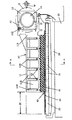
図1〜図4は、本発明を研削盤の砥石台案内機構として適用した第1の実施の形態を示す。図1において、摺動体としての砥石台10は、本体部11と、この本体部11の前部に形成されたL字形取付面11D上に着座してボルト12により固着された砥石軸受ユニット13からなる。ユニット13は、砥石台10の進退方向と直交する水平な軸線上で砥石軸14を回転自在に支持している。砥石軸14は、図1における奥側の一端において図略の砥石駆動モータの出力軸に結合され、手前側の他端において砥石車Gを固着している。
砥石台10が前進した図1の状態では、図略の主軸台及び心押台からなる工作物支持装置により砥石軸14と平行な水平軸上で回転されるようにセンタ支持された工作物であるカムシャフト上のカムWを砥石車Gが研削加工している。
Hereinafter, embodiments of the present invention will be described with reference to the drawings.
1 to 4 show a first embodiment in which the present invention is applied as a grinder support mechanism for a grinding machine. In FIG. 1, a
In the state of FIG. 1 in which the
図2から明らかなように、砥石台本体11は、進退方向と直交な水平方向に離間して平行に延びる断面が矩形の一対の水平ガイド板20、20上で摺動自在に案内されている。つまり、砥石台本体11の両側部下面には脚部11K、11Kが垂下され、これら脚部の下端に固着した一対の挟み板21、21によって外方に開くコの字形空間が砥石台本体11の全長に亘って形成され、このコの字形空間内にガイド板20、20をそれぞれ所定の隙間を有して嵌合することにより、砥石台本体11が水平方向に案内される。挟み板21、21の内側面は、直線ガイド板22の両側面と所定の隙間を有して対向している。一対の水平ガイド板20、20及び直線ガイド板22は、砥石台本体11の長手方向の略全長と進退ストロークSTを加えた長さに設定され、研削盤のベッド25に定着された固定ベース26にボルトにより固着されている。
As apparent from FIG. 2, the
図3に示すように、砥石台本体11の水平ガイド板20、20の上面と対向する下向き案内面には、長方形の複数の静圧ポケット27、27が長手方向に配置され、これらポケットに油圧を供給する絞り穴28がそれぞれ設けられている。同様に、挟み板21、21の水平ガイド板20、20の下面と対向する上向き案内面には、長方形の複数の静圧ポケット29、29が長手方向に配置され、これらポケットに圧油を供給する絞り穴(図示省略)がそれぞれ設けられている。静圧ポケット29、29内に発生する圧油の静圧力が砥石台10を下方に押し下げる押下力は、静圧ポケット27、27内に発生する圧油の静圧力が砥石台10を浮上させる浮力を後述するリニアモータの磁気吸引力及び砥石台10の自重と共に相殺するように設定してある。
As shown in FIG. 3, a plurality of rectangular
押下力をこのように設定するため、この実施の態様においては、静圧ポケット29の設計諸元は、静圧ポケット27に対して砥石台10の長手方向を横切る幅方向の幅を狭くしてある。静圧ポケット27に対して静圧ポケット29の設計諸元を変える別の方法としては、各静圧ポケット29の長さを短くしたり、或いは長さと幅の両方を小さくしたり、ポケット数を減らしたり、さらには絞り穴を小さくする方法が採用できる。
In order to set the pressing force in this way, in this embodiment, the design specifications of the
挟み板21、21の内側面には、挟み板21、21の全長に亘って複数の静圧ポケット31、31が配設されている。左側のポケット列と右側のポケット列は対称構成となっており、図3に示す左右の静圧ポケット27の列と同一構成となっている。左右のポケット列の各静圧ポケット31、31には図略の絞り穴を介して圧油が供給され、これらポケット内に発生される圧油の静圧力により、左右の挟み板21、21は直線ガイド板22の左右両端面から所定の隙間を有して位置決めされ、これにより砥石台本体11が直線ガイド板22に沿って進退できるようになっている。
なお、静圧ポケット27、29及び31へ圧油を供給するため、固定部に設置した図略の油圧源と砥石台本体11との間に図略のフレキシブル管が接続され、砥石台本体11及び挟み板21、21内にはフレキシブル管から各ポケットに開口する絞り穴まで圧油を導く通路が形成されている。
A plurality of static pressure pockets 31, 31 are disposed on the inner side surfaces of the
In order to supply pressure oil to the static pressure pockets 27, 29 and 31, a not-illustrated flexible pipe is connected between a not-illustrated hydraulic power source installed in the fixed portion and the
リニアモータ40は、砥石台本体11の下面に配置され、電磁コイルユニット41と永久磁石板ユニット42とからなる。電磁コイルユニット41は、砥石台本体11の幅方向の下面中央において長手方向に形成された断面矩形のコイル空間に収納され、砥石台本体11の上面側から挿入される複数のボルト43によりその空間の天井面に固着されている。図1及び図3を参照して明らかなように、コイルユニット41は、砥石台本体11の長手方向全長に亘って設けられておらず、後側は砥石台本体11の後端部まで延びているが、前側は砥石軸受ユニット13の下方には至らないようにしてある。図3には、静圧ポケット27は砥石軸受ユニット13の直下まで配置されているが、コイルユニット41は砥石軸受ユニット13の直下の手前で終端となっていることが示されている。
The
本発明が特徴の1つとする斯かる構成の採用によって、軸受ユニット13の自重が作用する砥石台本体11の前部では磁気吸引力が作用しないようにし、砥石台本体11の長手方向全長に沿う各位置で案内面が受持つ、つまり各静圧ポケット27が受持つ下向き方向の荷重をほぼ均等にしている。
永久磁石板ユニット42は、砥石台10が図1で実線で示す前進位置及び鎖線で示す後退位置の何れに位置する場合でもコイルユニット41とこのユニットの長手方向の全長に亘って対面するように固定ベース26のほぼ全長に亘って直線ガイド板22の上面に敷設されている。コイルユニット41の下面と永久磁石板ユニット32の上面との間には所定の間隔が保たれている。
By adopting such a configuration as one of the features of the present invention, the magnetic attraction force is prevented from acting at the front portion of the
The permanent
本発明の他の特徴として、コイルユニット41と永久磁石板ユニット42との対接面位置が水平ガイド板20、20の上下面間に設定され、これにより水平方向の案内中心とリニアモータ40の推力発生部が実質的に同一高さとなり、砥石台10のピッチングをもたらすモーメントが発生しないようにしている。
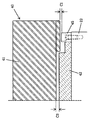
本発明の別の特徴として、図4において一部拡大して示すように、永久磁石板ユニット42の左右両側には、受部材45、45が設けられている。この受部材45、45は、ボルト43を緩めてコイルユニット41が砥石台本体11の下面との固着状態から解かれたとき、コイルユニット41の下面が磁石板ユニット42の上面に密着されないようにコイルユニット41の両端を仮受する役目をする。このため、受部材45、45とコイルユニット41との間の隙間C1がコイルユニット41と磁石板ユニット42の対接面間の隙間C2よりも狭くなるように受部材45、45の高さ位置が決めれている。
As another feature of the present invention, the position of the contact surface between the
As another feature of the present invention, as shown in a partially enlarged view in FIG. 4, receiving
好ましくは、受部材45は、合成樹脂などの低摩擦係数の非磁性材料にて形成され、磁石板ユニット42と同一長さを持っている。これにより、コイルユニット41は、ボルト43を緩めて砥石台本体11から外されたとき、受台45、45に仮受けされ、この受台上で後方へ容易に引き抜かれる。
Preferably, the receiving
砥石台本体11は、例えばカム研削盤の場合では、カムWの回転に同期して前進動作と後退動作を高い加速度で繰り返し実行する。このため、砥石台本体11は軽量でかつ剛性が大きいな構造であることが要求される。図1に示すように、砥石台本体11は、長手方向の所定間隔位置で幅方向に延びる複数の隔壁11Mが配置され、隣接する隔壁11M同士間及び前後壁11F、11Bと隣接する隔壁11Mとの間に概略箱形空間11Sを形成して軽量化と高剛性化が図られている。コイルユニット41を砥石台本体11下面に固着するボルト43は、六角穴付ボルトが用いられ、前後壁11F、11B及び隔壁11Mの上面側から明けられたボルト穴に挿入されている。
In the case of a cam grinder, for example, the
各箱形空間11S内には砥石台本体11の長手方向に延びて前後壁11F、11Bと隔壁11Mに一体結合する一対のリブ11R、11Rが設けられている。図2に示す砥石台本体11の幅方向の断面で観察するとき、この一対のリブ11R、11Rは、砥石台本体11の下面部から始まり互いに外方に開いて天井面に一体結合されている。本発明のさらに別の特徴として、リブ11R、11Rをこのように傾斜配置することにより、砥石台本体11の幅方向断面の中央には概ね逆台形空間11Vが形成され、この空間11Vの両隣りには三角形空間11Tが形成される。この逆台形空間11Vは、より正確には、この空間の天井面では幅方向の中央部が一番高く、この一番高い部分から両側に向けて下向きに傾斜したダイヤモンド六角形となっている。
In each box-shaped
本発明の付加的な特徴として、挟み板21、21を固着する砥石台本体11の一対の脚部11K、11Kは、それぞれ三角形空間11T、11Tを形成する部分から下方に垂下され、中央の逆台形空間11Vを形成する部分が両側の三角形空間11T、11Tを形成する部分を相互に結合し、これら三角形空間形成部分が互いに接近する内方へ変形偏奇することを阻止している。換言すれば、各箱形空間の横断面は、2つの三角トラス構造を中央の逆台形(正確には、ダイヤモンド六角形)トラス構造により結合した構造にしてある。
As an additional feature of the present invention, the pair of
図5は、一対の脚部11K、11Kを開き方向に偏奇させるときにこれら脚部を支える砥石台本体11の主体部内に作用する応力の方向と大きさをコンピュータにより解析したコンピュータ解析図である。この解析においては、砥石台本体11の主体部は内部に空間を持たない中実の矩形断面形状として設定してある。この解析図は、応力が殆ど作用していない黒色部分BP、若干作用している濃い灰色部分GP1と、応力が集中している薄い灰色部分GP2、最大の応力集中を受ける白色部分WPとを明確に区別して示している。図2に示す砥石台本体11の断面形状は、内部応力が殆ど作用しない黒色部分BPと濃い灰色部分GP1を削ぎ落とし、内部応力が集中する白色部分WPと薄い灰色部分GP2を残したトラス構造として、砥石台本体11の剛性アップと軽量化を両立させている。
FIG. 5 is a computer analysis diagram in which the direction and magnitude of the stress acting in the main portion of the
さらに、砥石台10の砥石車15を配置する一側において、リニアスケール51がブラケット52を介して水平ガイド板20と平行にして固定ベース26に支持され、リニアスケール51の上方にはこのスケールと僅かな隙間を有して対向する読取りヘッド53が砥石台本体11に取付られている。読取りヘッド53はリニアスケール51に記憶された目盛り情報を検出して砥石台10の進退方向における位置を検出し、この検出位置情報をフィードバック情報として図略のCNC装置へ入力するように構成されている。
Further, on one side of the
次に、上記のように構成された第1の実施形態の動作を説明する。図略のCNC装置からの指令によりリニアモータ40のコイルユニット41に駆動電流が与えられるとき、コイルユニット41は磁石板ユニット42と協働し、この磁石板ユニット42に沿う方向の駆動推力を発生する。このため、砥石台10は進退送りされ、この進退位置がリニアスケール51上の目盛り情報を読取る読取りヘッド53により検出され、CNC装置が指令する目標位置と読取りヘッド53の読取る砥石台10の現在位置が一致するように砥石台10は送り制御される。
Next, the operation of the first embodiment configured as described above will be described. When a drive current is applied to the
この進退動作において、砥石台10は一対の水平ガイド板20、20により水平方向に案内される。各ガイド板20の上面に対向する複数の静圧ポケット27内及び下面に対向する複数の静圧ポケット29内に生起される圧油の静圧力により砥石台10は水平ガイド板20、20に対し僅か浮上して円滑に移動される。この場合、直線ガイド板22の両側面に対向する静圧ポケット31、31内にも圧油の静圧力が生起され、砥石台10は直線ガイド板22の両側面に対し僅かな隙間を保持してこの直線ガイド板22に沿って直進される。
In this advance / retreat operation, the
リニアモータ40の駆動推進力は、高さ方向において、水平ガイド板20、20の上下案内面間、つまり水平ガイド板20、20の案内中心と同じ高さ位置において生起されるので、砥石台10にピッチングをもたらすようなモーメントが発生されない。
The driving driving force of the
コイルユニット41が発生する磁気吸引力により、砥石台10は、固定ベース26に押しつけられる。砥石台10の下方への押しつけ力は、この磁気吸引力に加えて、砥石台10の自重及び水平ガイド板20、20の下面に向かって開口する複数の静圧ポケット29がこの下面対し油圧の静圧力により作用する押下力が加わる。水平ガイド板20、20の上部案内面上で浮力を発生する複数の静圧ポケット27は、砥石台10を下方に押し下げようとするこれら磁気吸引力、砥石台10の自重及び前記押下力を相殺する浮力を発生する。
The
砥石台10の前部に取り付けた軸受ユニット13の直下には、コイルユニット41を配置しないようにして、軸受ユニット13の重量がさらに水平ガイド板20、29に負荷されることを防止している。このため、砥石台10の前部に対し下向き荷重が偏重されることがなく、砥石台10が一層円滑に進退される。また、砥石台10の長手方向全長に亘る各位置において水平ガイド板20、20には略均等の下向き力が作用する。これにより、水平ガイド板20、20に作用する静圧ポケット27の列及び静圧ポケット29の列を各列内で砥石台11の長手方向全長に亘って同一の構造とすることができる。
The
砥石台10の自重と磁気吸引力の合力は、砥石台本体11の下面に配置した一対の脚部11K、11Kを開き方向に作用する。この開き方向の力に対向するため、砥石台本体11にリブ11R、11Rを配置し、各脚部11Kを三角形空間11T、11Tを形成する部分、つまり三角形トラス構造により支えるようにしてある。特に、左右2つの三角形空間形成部分を概ね逆台形空間11Vを形成する部分である逆台形トラス構造により一体結合してあるので、左右の三角形空間形成部分の頂部が互いに内方へ変位することを阻止でき、一対の脚部11K、11Kの開き方向変位は確実に阻止される。これにより、水平ガイド板20、20に沿う砥石台10の案内精度を当所の設計値に保証できる。
The resultant force of the weight of the
電磁コイルユニット41を保守のために点検し或いは交換する場合、コイルユニット41を砥石台10から取り外す必要がある。この場合、砥石台本体11の上面に開口するボルト穴に六角レンチを挿入してボルト43を緩める。ユニット41は、ボルト43とのネジ係合から外れると、磁石板ユニット42が生起している磁力によりこの磁石板ユニットに吸着されようとする。このとき、コイルユニット41の幅方向の両端は、受部材45に仮受けされ、この状態においてコイルユニット41を受部材45上を滑らせて砥石台10の後方へ引き出し、研削盤の機外へ取り出す。点検後にそのコイルユニット41が、或いは予備コイルユニットが上述した逆の手順で砥石台本体11の下面に固着される。
When the
図6は、本発明の第2の実施の形態を示す。上述した第1の実施の態様を示す図2との対比から明らかなように、この実施の態様においては、第1の実施の態様における直線ガイド板22を除去し、この直線ガイド板22の直線案内作用を一対の水平ガイド板20、20に代行させるようにしている。より詳細には、一対の水平ガイド板20、20の内側面を砥石台本体11の脚部11K、11Kの外側面と所定の隙間を有して対向させ、この外側面の各々に複数の静圧ポケット131、131を形成する。この静圧ポケットの構成及び配置は、図2に示す挟み板21、21の内側面に形成した静圧ポケット31と同一の構成とされる。この実施の態様におけるその他の構成は、図2を参照して上述した第1の実施の態様と同様である。
FIG. 6 shows a second embodiment of the present invention. As is clear from the comparison with FIG. 2 showing the first embodiment described above, in this embodiment, the
このように構成することにより、水平ガイド板20、20の上下面向かって開口する静圧ポケット27、29により構成される水平案内中心と、直線案内の中心と、リニアモータ40の推進力作用点とは、全て同一の高さ位置となる。この結果、砥石台10は、ピッチングやヨーイングの挙動をせずに円滑に進退送りされる。なお、永久磁石板ユニット42は、固定ベース26に直接固定される。
With this configuration, the horizontal guide center formed by the static pressure pockets 27 and 29 opening toward the upper and lower surfaces of the
上述した各実施の形態においては、本発明による案内機構を研削盤の砥石台に適用した例について説明したが、この案内機構に案内される摺動体は切削工具を支持する旋盤やマシニングセンタ等の切削工作機械の工具台や、工作物を支持するテーブルとして構成しても良い。
また、上述した各実施の態様における水平案内機構は、一対の水平ガイド板20、20の内側からこれらガイド板の上下面を挟む構造としているが、ガイド板を外側から抱きかかえるような構造としてもよく、或いはガイド板の上下面を挟む構造とはせずに挟み板21、21を取り除いても良い。
また、隔壁11Mは必ずしも必要でなく、この隔壁11Mを除去した場合は一対のリブ11R、11Rが前後壁11F、11Bの間で砥石台本体11を貫くようにしてもよい。
In each of the above-described embodiments, the example in which the guide mechanism according to the present invention is applied to the grinding wheel head is described. However, the sliding body guided by the guide mechanism is a cutting machine such as a lathe or a machining center that supports a cutting tool. You may comprise as a tool stand of a machine tool, or a table which supports a workpiece.
In addition, the horizontal guide mechanism in each of the above-described embodiments has a structure in which the upper and lower surfaces of the guide plates are sandwiched from the inside of the pair of
Further, the
26・・・固定ベース、 20、20・・・水平ガイド板、 10・・・砥石台、 11・・・砥石台本体、 40・・・リニアモータ、 41・・・電磁コイルユニット、 42・・・永久磁石板ユニット、 43・・・ボルト(固着手段)、 45、45・・・受部材、 13・・・砥石軸受ユニット(工具支持ユニット)、 11V・・・逆台形空間、 11T、11T・・・三角形空間、 11R、11R・・・リブ、 11K、11K・・・脚部、 21、21・・・挟み板、 22・・・直線ガイド板。 26: Fixed base, 20, 20: Horizontal guide plate, 10: Grinding wheel base, 11: Grinding wheel base body, 40 ... Linear motor, 41 ... Electromagnetic coil unit, 42 ... -Permanent magnet plate unit, 43 ... Bolt (fixing means), 45, 45 ... Receiving member, 13 ... Grinding wheel bearing unit (tool support unit), 11V ... Inverted trapezoidal space, 11T, 11T -Triangular space, 11R, 11R ... ribs, 11K, 11K ... legs, 21, 21 ... sandwiching plates, 22 ... linear guide plates.
Claims (1)
Priority Applications (1)
| Application Number | Priority Date | Filing Date | Title |
|---|---|---|---|
| JP2006279393A JP4508176B2 (en) | 2006-10-13 | 2006-10-13 | Guide mechanism for sliding bodies in machine tools |
Applications Claiming Priority (1)
| Application Number | Priority Date | Filing Date | Title |
|---|---|---|---|
| JP2006279393A JP4508176B2 (en) | 2006-10-13 | 2006-10-13 | Guide mechanism for sliding bodies in machine tools |
Related Parent Applications (1)
| Application Number | Title | Priority Date | Filing Date |
|---|---|---|---|
| JP2000007871A Division JP4016561B2 (en) | 2000-01-17 | 2000-01-17 | Guide mechanism for sliding bodies in machine tools |
Publications (3)
| Publication Number | Publication Date |
|---|---|
| JP2007050511A JP2007050511A (en) | 2007-03-01 |
| JP2007050511A5 JP2007050511A5 (en) | 2007-04-12 |
| JP4508176B2 true JP4508176B2 (en) | 2010-07-21 |
Family
ID=37915295
Family Applications (1)
| Application Number | Title | Priority Date | Filing Date |
|---|---|---|---|
| JP2006279393A Expired - Lifetime JP4508176B2 (en) | 2006-10-13 | 2006-10-13 | Guide mechanism for sliding bodies in machine tools |
Country Status (1)
| Country | Link |
|---|---|
| JP (1) | JP4508176B2 (en) |
Citations (6)
| Publication number | Priority date | Publication date | Assignee | Title |
|---|---|---|---|---|
| JPH0919844A (en) * | 1995-07-05 | 1997-01-21 | Toyoda Mach Works Ltd | Feeding device with liner motor |
| JPH09150334A (en) * | 1995-11-24 | 1997-06-10 | Toyoda Mach Works Ltd | Linear motor-driven feed device for machine tool |
| JPH10328954A (en) * | 1997-05-23 | 1998-12-15 | Canon Inc | Positioining table device and estimation of initial position |
| JPH11216633A (en) * | 1998-02-04 | 1999-08-10 | Toyoda Mach Works Ltd | Linear motor driven type machine tool |
| JP2000512216A (en) * | 1996-05-21 | 2000-09-19 | ユノーヴァ インダストリアル オートメイション システムズ インコーポレイテッド | Drive / support device for machine tools |
| JP2000354931A (en) * | 1999-06-09 | 2000-12-26 | Toyoda Mach Works Ltd | Linear motor driving and feeding device for machine tool |
-
2006
- 2006-10-13 JP JP2006279393A patent/JP4508176B2/en not_active Expired - Lifetime
Patent Citations (6)
| Publication number | Priority date | Publication date | Assignee | Title |
|---|---|---|---|---|
| JPH0919844A (en) * | 1995-07-05 | 1997-01-21 | Toyoda Mach Works Ltd | Feeding device with liner motor |
| JPH09150334A (en) * | 1995-11-24 | 1997-06-10 | Toyoda Mach Works Ltd | Linear motor-driven feed device for machine tool |
| JP2000512216A (en) * | 1996-05-21 | 2000-09-19 | ユノーヴァ インダストリアル オートメイション システムズ インコーポレイテッド | Drive / support device for machine tools |
| JPH10328954A (en) * | 1997-05-23 | 1998-12-15 | Canon Inc | Positioining table device and estimation of initial position |
| JPH11216633A (en) * | 1998-02-04 | 1999-08-10 | Toyoda Mach Works Ltd | Linear motor driven type machine tool |
| JP2000354931A (en) * | 1999-06-09 | 2000-12-26 | Toyoda Mach Works Ltd | Linear motor driving and feeding device for machine tool |
Also Published As
| Publication number | Publication date |
|---|---|
| JP2007050511A (en) | 2007-03-01 |
Similar Documents
| Publication | Publication Date | Title |
|---|---|---|
| US6161995A (en) | Machine tool | |
| JP4016561B2 (en) | Guide mechanism for sliding bodies in machine tools | |
| JP4427689B2 (en) | Machine Tools | |
| JP2007237375A (en) | Compound machine tool | |
| JP4382099B2 (en) | Machine Tools | |
| JP4508177B2 (en) | Guide mechanism for sliding bodies in machine tools | |
| JP4508176B2 (en) | Guide mechanism for sliding bodies in machine tools | |
| KR20170039790A (en) | Shear beam device and bur removal device having the same | |
| US7220090B2 (en) | Linear motor operated machine tool | |
| JP2006192481A (en) | Die cushion device | |
| JP4521009B2 (en) | Work table moving device | |
| JP2017507035A (en) | Tool slide | |
| JP2017507036A (en) | Tool slide | |
| KR20110002163U (en) | Machine tools | |
| JP2014018956A (en) | Lathe | |
| JP2017508626A (en) | Tool slide | |
| US6336744B1 (en) | Linear drive and process for assembly and dismantling of said linear drive | |
| JP4443370B2 (en) | Machine Tools | |
| JP2008114352A (en) | Grinding device | |
| JPH11216633A (en) | Linear motor driven type machine tool | |
| JP2009012169A (en) | Machining tool and linear drive device including functional unit having this linear drive device | |
| JP4735162B2 (en) | Structure of sliding body in machine tool | |
| JP4874673B2 (en) | Machine Tools | |
| JP2006159374A (en) | Machine tool with linear guide device, and linear guide changing method | |
| JP4255669B2 (en) | Automatic lathe |
Legal Events
| Date | Code | Title | Description |
|---|---|---|---|
| A521 | Written amendment |
Free format text: JAPANESE INTERMEDIATE CODE: A523 Effective date: 20070117 |
|
| A621 | Written request for application examination |
Free format text: JAPANESE INTERMEDIATE CODE: A621 Effective date: 20070117 |
|
| TRDD | Decision of grant or rejection written | ||
| A01 | Written decision to grant a patent or to grant a registration (utility model) |
Free format text: JAPANESE INTERMEDIATE CODE: A01 Effective date: 20100413 |
|
| A01 | Written decision to grant a patent or to grant a registration (utility model) |
Free format text: JAPANESE INTERMEDIATE CODE: A01 |
|
| A61 | First payment of annual fees (during grant procedure) |
Free format text: JAPANESE INTERMEDIATE CODE: A61 Effective date: 20100426 |
|
| FPAY | Renewal fee payment (event date is renewal date of database) |
Free format text: PAYMENT UNTIL: 20130514 Year of fee payment: 3 |
|
| R150 | Certificate of patent or registration of utility model |
Ref document number: 4508176 Country of ref document: JP Free format text: JAPANESE INTERMEDIATE CODE: R150 Free format text: JAPANESE INTERMEDIATE CODE: R150 |
|
| FPAY | Renewal fee payment (event date is renewal date of database) |
Free format text: PAYMENT UNTIL: 20140514 Year of fee payment: 4 |
|
| EXPY | Cancellation because of completion of term |