JP4504522B2 - Image quality correction device - Google Patents
Image quality correction device Download PDFInfo
- Publication number
- JP4504522B2 JP4504522B2 JP2000205479A JP2000205479A JP4504522B2 JP 4504522 B2 JP4504522 B2 JP 4504522B2 JP 2000205479 A JP2000205479 A JP 2000205479A JP 2000205479 A JP2000205479 A JP 2000205479A JP 4504522 B2 JP4504522 B2 JP 4504522B2
- Authority
- JP
- Japan
- Prior art keywords
- jitter
- signal
- video signal
- amount
- image quality
- Prior art date
- Legal status (The legal status is an assumption and is not a legal conclusion. Google has not performed a legal analysis and makes no representation as to the accuracy of the status listed.)
- Expired - Fee Related
Links
Images


Description
【0001】
【発明の属する技術分野】
本発明は、映像信号に種々の処理を施して、映像信号より再生される画像の品質を補正する画質補正装置に関し、さらに詳述すれば、画像品質に多大な影響を与える映像信号のジッター量に応じた適正な補正量で画質補正する画質補正装置に関する。
【0002】
【従来の技術】
図22に、LCDやCRTに代表されるテレビジョンセットで用いられている画像表示器において表示される画像の源であるアナログの映像信号Svに対して用いられる従来の画像補正装置を示す。同図に示すように、テレビジョンセットにおいて、信号処理システムSPcは映像信号Svに種々の処理を施して、画像表示器9(本例においては、CRT)において画像を表示させるために必要な、画像表示器9の特性に応じた情報を表すスキャン速度変調信号VSCc、画像信号Si、および水平同期信号Hsyncと垂直同期信号Vsyncを生成する。
【0003】
スキャン速度変調信号VSCcに基づいて、スキャン速度変調駆動器6は画像表示器9における表示画質を補正するために、所定の速度でスキャンさせて画質補正スキャン駆動信号Sscdを生成する。画像信号Siに基づいて、CRT駆動器7は画像表示器9に画像を表示させるCRT駆動信号Scrtdを生成する。同期信号Ssyncに基づいて、偏向器8は画像表示器9を所定の偏向量で動作させラスタスキャンさせる偏向駆動信号Sdfdを生成する。画像表示器9は、これらの駆動信号Sscd、Scrtd、およびSdfdによって駆動されて、映像信号Svが運んでいる画像を表示する。
【0004】
信号処理システムSPcは、同期分離器4、画質補正装置IQCc、および信号処理器5を含む。同期分離器4は、映像信号Svから水平同期信号Hsyncおよび垂直同期信号Vsyncを抽出する。
画質補正装置IQCcは、水平同期信号Hsyncおよび垂直同期信号Vsyncに基づいて、映像信号Svに画質補正処理を施して被画質補正映像信号SIQcを生成すると共に、スキャン速度変調信号VSCcを生成する。信号処理器5は、被画質補正映像信号SIQcに基づいて、画像信号Siを生成する。なお、信号処理システムSPcの動作は制御器100cによって制御される。
【0005】
画質補正装置IQCcは、画像表示器9によるスキャン速度VSCを規定するスキャン速度変調信号生成器11、画像信号Siの水平輪郭強調量OEを規定する水平輪郭強調器12、画像信号Siに含まれるノイズ成分を低減するノイズ低減器(NR)13、マルチプレクサ14、バスインターフェース15、およびROM16を含む。
【0006】
スキャン速度変調信号生成器11は、水平同期信号Hsyncおよび垂直同期信号Vsyncと映像信号Svに基づいて、画像信号Siに対応したラスタスキャン速度VSC(図示せず)を決定する。同様に、水平輪郭強調器12は、水平同期信号Hsyncおよび垂直同期信号Vsyncと映像信号Svに基づいて、映像信号Svの水平輪郭強調量OE(図示せず)を決定する。
【0007】
仮に映像信号Svの品質が一定であったとしても、映像信号Svの運ぶ映像が画像表示器9で表示される場合には、画像表示器9およびスキャン速度変調駆動器6、CRT駆動器7、および偏向器8を含む駆動回路系や、信号処理系を含めたテレビジョンセットの物理特性等の影響を受けるので、上述のスキャン速度VSCおよび水平輪郭強調量OEを水平同期信号Hsync、垂直同期信号Vsync、および映像信号Svに基づいて一義的に決定することはできない。そのために、画質補正装置IQCcが用いられるテレビジョンセットの物理的特性に応じて、スキャン速度変調信号生成器11、水平輪郭強調器12、およびNR13の作用をそれぞれ補正する所定の補正量を予め求めておく。
【0008】
そして、それぞれ所定補正量SCAcをROM16中に格納しておいて、画質補正装置IQCcにおける映像信号Svの画質補正時に、バスインターフェース15を経由して、所定補正量SCAcをROM16から読み出して、スキャン速度変調信号生成器11、水平輪郭強調器12、およびNR13に供給して、それぞれの作用を補正する。
【0009】
具体的には、所定補正量SCAcには、スキャン速度変調信号生成器11によって決定されるスキャン速度VSCに対する所定の補正量であるスキャン速度補正量SVMc、水平輪郭強調器12によって決定される水平輪郭強調量OEに対する所定の補正量である水平輪郭強調補正量SOEc、およびNR13におけるノイズ低減量に対する所定の補正値であるノイズ低減補正量SNRcが含まれる。
【0010】
このように、水平輪郭強調器12は、バスインターフェース15を経由してROM16から供給される水平輪郭強調補正SOEcに基づいて、映像信号Svの水平輪郭強調量OEを決定して被補正水平輪郭強調信号OEcを生成する。マルチプレクサ14は映像信号Svと被補正水平輪郭強調信号OEcとを多重化して、映像信号Svの水平輪郭が水平輪郭強調量OEで強調された水平輪郭被強調映像信号VOEcを生成してNR13に出力する。
【0011】
NR13は、水平輪郭強調器12と同様に、バスインターフェース15を経由してROM16から供給されるノイズ低減補正量SNRcによって補正されたノイズ低減特性に基づいて、水平輪郭被強調映像信号VOEcのノイズを低減して被画質補正映像信号SIQcを生成する。
信号処理器5は、被画質補正映像信号SIQcに基づいて、画像信号Siを生成する。
【0012】
【発明が解決しようとする課題】
上述のように、従来の画質補正装置IQCcにおいては、テレビジョンセットの物理特性等の影響を考慮し所定量だけ、映像信号Svに対して、スキャン速度変調、水平輪郭強調量、およびノイズ低減の補正を行っている。つまり、映像信号Svの品質の変化に関わらず、画質補正装置IQCcによる補正量は常に一定である。
【0013】
しかしながら、映像信号Svの品質は時間の経過と共に変化している。映像信号Svがジッタしている場合には、画質補正装置IQCcから出力される被画質補正映像信号SIQcおよびスキャン速度変調信号VSCcもジッタを起こす。よって、これらジッタを起こしている被画質補正映像信号SIQcおよびスキャン速度変調信号VSCcに基づいて、画像表示器9において再生される映像のジッタ量も増大するので、再生映像そのものの品質が劣化してしまう。
【0014】
例えば、ジッタを有する映像信号Svに、強くエッジ強調する水平輪郭強調処理を施すと、水平輪郭強調信号自体もジッタしているので、エッジ部分のぎらつきを強調し、画質補正処理が再生画像のジッタを強調してしまう。これを防ぐには、映像信号Svのジッタ量に応じて、エッジ強調型の画質補正量は減じ、ノイズ除去型の画質補正量を増加させれば良い。
【0015】
つまり、映像信号Svの品質(ジッタ)に起因する映像画像の品質劣化を防止あるいは改善するためには、映像信号Svのジッタ量に応じて、スキャン速度変調信号生成器11、水平輪郭強調器12、およびNR13による補正を調整すれば良い。つまり、映像信号Svがジッタしている場合には、そのジッタ量に応じてスキャン速度変調信号生成器11および水平輪郭強調器12による補正を抑える一方、NR13による補正を促進するのである。
【0016】
そのためには、映像信号Svのジッタの有無およびジッタ量を正確に検出できることが必須である。しかしながら、従来テレビジョンセットのような画像表示装置に組み込んで、入力される映像信号Svのジッタの有無およびその量を正確に検出する手段は提供されていない。
それゆえに、本発明は上記の課題を解決するために成されたもので、映像信号のジッタの有無およびそのジッタ量を正確に検出できる映像信号のジッタ検出装置を提供することを第1の目的とし、さらに該ジッタ検出装置にて検出映像信号のジッタ量に応じて映像信号を再生する際の画質補正量を適応的に変化させて再生画像の画質補正を行う画質補正装置を提供することを第2の目的としている。
【0017】
【課題を解決するための手段および発明の効果】
上記課題を解決するために、第1の発明は、映像信号のジッタを検出するジッタ検出装置であって、
映像信号の1フィールドの垂直時間を測定して垂直時間信号を生成する垂直時間測定器と、
垂直時間信号に基づいて、映像信号がジッタしているか否かを判定してジッタ判定信号を生成するジッタ判定器と、
ジッタ判定信号に基づいて、映像信号がジッタしていると連続して判定される回数をカウントしてジッタ判定カウンタ信号を生成するジッタ判定カウント器と、
ジッタ判定カウンタ信号に基づいて、映像信号が第1の所定回数連続してジッタしていると判定される場合には映像信号をジッタ信号と認定するジッタ認定器と、
ジッタ判定信号に基づいて、映像信号がジッタしていないと連続して判定される回数をカウントして非ジッタ判定カウンタ信号を生成する非ジッタ判定カウント器と、
非ジッタ判定カウンタ信号に基づいて、映像信号が第2の所定回数だけ連続してジッタしていないと判定される場合に映像信号を非ジッタ信号と認定する非ジッタ認定器と、
垂直時間の分散値を逐次算出するジッタ量算出器とを備える。
【0018】
上記のように、第1の発明においては、映像信号やテレビジョン装置側のノイズ成分等の擾乱因子の影響を排除して、映像信号のジッタ状態およびジッタ量を正確に検出できる。
【0019】
第2の発明は、第1の発明において、ジッタ判定器は、
現フィールドの垂直時間と前フィールドの垂直時間Stfの差の絶対値が1より大きい時には、映像信号はジッタしていると判定し、
絶対値が1より小さい時には、映像信号はジッタしていないと判定することを特徴とする。
【0021】
第3の発明は、映像信号のジッタ量に応じて、映像信号の画質を補正する画質補正装置であって、
所定のノイズ低減補正量に基づいて、映像信号ノイズを低減するノイズ低減器と、
所定の水平輪郭強調補正量に基づいて、映像信号の水平輪郭を強調する水平輪郭強調器と、
所定のスキャン速度変調量に基づいて、映像信号の特定の部分を強調するスキャン速度変調器との少なくとも一つを備え、
ジッタ量に応じて、ノイズ低減補正量は所定の調整値だけ増加させ、水平輪郭強調補正量は調整値だけ減少させ、スキャン速度変調量は調整値だけ減少させる画質補正調整器と、
映像信号の1フィールドの垂直時間を測定して垂直時間信号を生成する垂直時間測定器と、
垂直時間信号に基づいて、映像信号がジッタしているか否かを判定してジッタ判定信号を生成するジッタ判定器と、
ジッタ判定信号に基づいて、映像信号がジッタしていると連続して判定される回数をカウントしてジッタ判定カウンタ信号を生成するジッタ判定カウント器と、
ジッタ判定カウンタ信号に基づいて、映像信号が第1の所定回数連続してジッタしていると判定される場合には映像信号をジッタ信号と認定するジッタ認定器と、
ジッタ判定信号に基づいて、映像信号がジッタしていないと連続して判定される回数をカウントして非ジッタ判定カウンタ信号を生成する非ジッタ判定カウント器と、
非ジッタ判定カウンタ信号に基づいて、映像信号が第2の所定回数だけ連続してジッタしていないと判定される場合に映像信号を非ジッタ信号と認定する非ジッタ認定器とを備えるジッタ検出装置とを備え、
画質補正調整器は、垂直時間の分散値を逐次計算しながら動的にノイズ低減補正量、水平輪郭強調補正量、およびスキャン速度変調量の少なくとも1つを調整することを特徴とする。
【0022】
上記のように、第3の発明においては、映像信号のジッタ状態に応じて、適正に調整された画質補正ができる。
【0025】
第4の発明は、第3の発明において、画質補正調整器は、ジッタ量に対する出現頻度からなるヒストグラムを生成するヒストグラム器を更に備え、
画質補正調整器は、出現頻度で所定の閾値以上且つジッタ量に対応して予め定められた所定の調整量でノイズ低減補正量、水平輪郭強調補正量、およびスキャン速度変調量の少なくとも1つを調整することを特徴とする。
【0026】
第5の発明は、第3の発明において、映像信号が非ジッタ信号からジッタ信号に変化した直後には、現フィールドのジッタ量を調整値として用いることを特徴とする。
【0027】
第6の発明は、第3の発明において、映像信号がジッタ信号から非ジッタ信号に変われば、ノイズ低減補正量、水平輪郭強調補正量、スキャン速度変調量の少なくとも1つの調整を取りやめる調整抑制器を備える。
【0028】
【発明の実施の形態】
先ず、図1〜図14を参照して、本発明の実施形態にかかる画質補正装置について説明する。その後、図15〜図21を参照して、本発明の実施形態の変形例にかかる画質補正装置について詳しく述べる。
【0029】
実施形態について具体的に述べる前に、先ず本発明にかかる画質補正装置の基本的な概念について説明する。上述の如く、テレビジョンセットに代表される画像表示装置において、画像表示器において表示される画像の品質は大別して、映像信号の品質およびテレビジョンセットの物理的特性の影響を受ける。映像信号の品質はジッタやノイズであり、テレビジョンセットの物理的特性とは信号処理系の対ジッタ応答性および周波数特性と画像表示器のフォーカス性能およびガンマ特性である。
【0030】
一般に、画像表示器において表示される画像の品質を改善するには、映像信号に対する水平輪郭強調、画像表示器に対するラスタスキャン速度の輝度信号の変化に対する変調(以降、「スキャン速度変調」と称す)、および映像信号のノイズ成分の影響を低減するノイズ低減化処理がある。ジッタしている映像信号に対しては、水平輪郭強調およびスキャン速度変調は、再生画像品質を一層劣化させるので、抑える必要がある。一方、ノイズ低減化は再生画像の改善するので抑える必要はない。
【0031】
つまり、映像信号のジッタ量が多くなれば水平輪郭強調およびスキャン速度変調の高速化を抑える一方ノイズ低減化を促進すればよい。一方、映像信号のジッタ量が小さくなれば水平輪郭強調およびスキャン速度変調を促進し、ノイズ低減化を低減化すれば良い。このように、本発明においては、映像信号のジッタ量に応じて、水平輪郭強調、スキャン速度変調、およびノイズ低減化量を適正に調整することによって、画像表示器による再生画像品質の確保を図るものである。
【0032】
(実施形態)
図1に、本発明の実施形態にかかる画像補正装置をLCDやCRTに代表されるテレビジョンセットに用いられている様子を示す。同図に示すように、テレビジョンセットにおいて、信号処理システムSPpは映像信号Svに種々の処理を施して、画像表示器9(本例においては、CRT)において画像を表示させるために必要な、画像表示器9の特性に応じた情報を表すラスタスキャン速度変調信号VSCv、画像信号Si、および水平同期信号Hsyncと垂直同期信号Vsyncを生成する。
【0033】
スキャン速度変調信号VSCvに基づいて、スキャン速度変調駆動器6は映像信号Svの輝度変化の二次微分信号でラスタスキャン速度を変えることで、画像表示器9における表示画質を補正するスキャン駆動信号Sscdを生成する。画像信号Siに基づいて、CRT駆動器7は画像表示器9に画像を表示させるCRT駆動信号Scrtdを生成する。偏向器8は画像表示器9を所定の偏向角で動作させる偏向駆動信号Sdfdを生成する。画像表示器9は、これらの駆動信号Sscd、Scrtd、およびSdfdによって駆動されて、映像信号Svが運んでいる画像を表示する。
【0034】
信号処理システムSPpは、同期分離器4、画質補正装置IQCp、および信号処理器5を含む。同期分離器4は、映像信号Svから水平同期信号Hsyncおよび垂直同期信号Vsyncを抽出する。
【0035】
画質補正装置IQCpは、水平同期信号Hsyncおよび垂直同期信号Vsyncに基づいて、映像信号Svに画質補正処理を施して被画質補正映像信号SIQvを生成すると共に、スキャン速度変調信号VSCvを生成する。信号処理器5は、被画質補正映像信号SIQvに基づいて、画像信号Siを生成する。なお、信号処理システムSPpの動作は制御器100pによって制御される。なお、信号処理システムSPcの各構成要素は、それぞれ自身の状態を示す信号を生成して、制御器100pに状態信号Srとして出力する。制御器100p、入力された状態信号Srに基づいて、各構成要素の状態を認識して、各構成要素の動作を制御する制御信号Scを出力する。
【0036】
画質補正装置IQCpは、画像表示器9のスキャン速度VSCを規定するスキャン速度変調信号生成器11、画像信号Siの水平輪郭強調量OEを規定する水平輪郭強調器12、画像信号Siに含まれるノイズ成分を低減するノイズ低減器(NR)13、マルチプレクサ14、バスインターフェース15、ROM16および補正調整器CAを含む。
【0037】
ROM16には、画質補正装置IQCpが用いられるテレビジョンセットの物理的特性に応じて予め定められた、スキャン速度変調信号生成器11、水平輪郭強調器12、およびNR13の作用をそれぞれ補正する所定補正量SCAcが格納されている。これは、映像信号Svの品質が一定であったとしても、映像信号Svの運ぶ映像が画像表示器9で表示される場合には、画像表示器9およびスキャン速度変調駆動器6、CRT駆動器7、および偏向器8を含む駆動回路系や、信号処理系を含めたテレビジョンセットの物理特性等の影響を受ける。それ故に予め求められたスキャン速度VSC、水平輪郭強調量OE、およびノイズ低減量NRの所定補正量SCAcに基づいて、テレビジョンセットの物理的特性等の影響を補償するべく準備されているものである。
【0038】
補正調整器CAは、同期分離器4で抽出された垂直同期信号Vsyncに基づいて映像信号Svのジッタ量を測定し、測定されたジッタ量に応じたスキャン速度変調信号生成器11、水平輪郭強調器12、およびNR13のそれぞれの適正補正量を求める。そして、適正補正量に基づいて、ROM16から読み出した所定補正量SCAcを調整して、適正化補正量SCAvを生成する。
【0039】
具体的には、適正化補正量SCAvには、スキャン速度変調信号生成器11によって決定されるスキャン速度VSCに対する所定の補正量SVMを調整する補正量である適正化スキャン速度補正量SVMv、水平輪郭強調器12によって決定される水平輪郭強調量OEを調整する補正量である適正化水平輪郭強調補正量SOEv、およびNR13におけるノイズ低減量を調整する所定の補正値SNRを調整する補正量である適正化ノイズ低減補正量SNRvが含まれる。適正化補正量SCAvのそれぞれは、バスインターフェース15を経由して速度変調信号生成器11、水平輪郭強調器12、およびNR13に供給されて、それぞれの作用を補正する。
【0040】
スキャン速度変調信号生成器11は、水平同期信号Hsyncと垂直同期信号Vsync、映像信号Sv、および適正化スキャン速度補正量SVMvに基づいて、画像表示器9のラスタスキャン速度VSCを決定して適正化スキャン速度変調信号VSCvを生成する。
同様に、水平輪郭強調器12は、水平同期信号Hsyncと垂直同期信号Vsync、映像信号Sv、および適正化水平輪郭強調補正量SOEvに基づいて、映像信号Svの適正水平輪郭強調量OEvを決定して適正化被補正水平輪郭強調信号OEvを生成する。
【0041】
マルチプレクサ14は映像信号Svと適正化被補正水平輪郭強調信号OEvとを多重化して、映像信号Svの水平輪郭成分が適正化被補正水平輪郭強調信号OEvだけ強調された適正水平輪郭被強調映像信号VOEvを生成してNR13に出力する。
【0042】
NR13は、水平輪郭強調器12と同様に、バスインターフェース15を経由して補正調整器CAから供給される適正化ノイズ低減補正量SNRvに補正されたノイズ低減特性に基づいて、適正水平輪郭被強調映像信号VOEvのノイズ成分を低減して被画質補正映像信号SIQvを生成する。
【0043】
信号処理器5は、被画質補正映像信号SIQvに基づいて、画像信号Siを生成する。このようにして、垂直同期信号Vsyncに基づいて、補正調整器CAによって検出された映像信号Svのジッタ量に応じて最適化された補正量で、水平輪郭が強調され、ノイズ成分が低減され、且つ画像表示器9がラスタスキャン速度が変調されることによって、画像表示器9において高品位な画像が再現される。
【0044】
以下に、図2を参照して、補正調整器CAの構成およびその動作について説明する。図2に示すように、補正調整器CAは垂直時間計測器21、ジッタ検出器22、ジッタ量計測器23、および画質補正量算出器24を含む。
垂直時間計測器21は、同期分離器4から入力される垂直同期信号Vsyncに基づいて映像信号Svの現フィールドvの垂直時間を計測して垂直時間信号Stf(v)を生成する。
【0045】
ジッタ検出器22は、垂直時間計測器21から入力される垂直時間信号Stf(v)に基づいて、映像信号Svがジッタ信号Svjと非ジッタ信号Svjnの何れであるかを判断してジッタ検出信号Sjdを生成すると共に、映像信号Svがジッタ信号Svjからジッタ信号Svjに変わったことを示すジッタ遷移信号Sffを生成する。
【0046】
ジッタ量計測器23は、垂直時間計測器21から入力される垂直時間信号Stf(v)に基づいて、映像信号Svのジッタ量を検出してジッタ量信号Sdspを生成する。
画質補正量算出器24は、ジッタ検出器22から入力されるジッタ検出信号Sjdおよびジッタ量計測器23から入力されるジッタ量信号Sdspに基づいて、信号生成器11、水平輪郭強調器12、およびNR13の映像信号Svのジッタ量に応じたそれぞれの適正補正量を求める。そして、画質補正量算出器24は、求めた適正補正量に基づいて、ROM16から読み出した所定補正量SCAcを調整して、適正化補正量SCAv(SVMv、SOEv、およびSNR)を生成する。なお、補正調整器CAはCPUによって構成しても良いことは言うまでもない。
【0047】
次に、図9および図10を参照して、映像信号Svのジッタ/非ジッタを判別する特徴量について説明する。図9に、ジッタしていない映像信号Sv、つまり非ジッタ信号Svjnの特徴量を示す。同図において、左欄にはフィールドVが示され、中央欄には各フィールドにおける垂直時間Stf(V)が示され、右欄にはフィールド間垂直時間差△Stf(V)が示されている。垂直時間Stf(V)は、前フィールドの垂直時間Stf(V−1)と今フィールドの垂直時間Stf(V)の差である。
【0048】
同図に示すように、非ジッタ信号Svjnは、フィールドV=0〜n−1(任意の正の整数)において、フィールド間垂直時間差△Stf(V)は−1、0、1の範囲内に収まる。このような非ジッタ信号Svjnは、カラーバースト信号の周波数と、水平周波数および垂直周波数とは同期しており、標準信号と呼ばれる。
【0049】
カラーバースト信号の4逓倍(4Fsc)のクロックで、水平および垂直それぞれの周期を計測すると、水平周期は910CLKに、垂直周期は910CLK×262.5=238875となる。それぞれの値を16進法で標記すると、水平周期は38e水平カウンタ値で表され、垂直周期は3a51b垂直カウンタ値で表される。本実施形態において垂直期間を計測するクロックは、バーストにロックした4Fscクロックであり、水平同期にロックしているのではないので、±1CLK以下の計測誤差が生じ得る。それゆえ、前フィールドとの垂直時間Stf(V)の差、つまりフィールド間垂直時間差△Stf(V)は、±2CLK以下になる。
【0050】
しかしながら、水平同期信号Hsyncおよび垂直同期信号Vsyncは安定したバースト信号からカウントダウンして作成されているので、フィールド間垂直時間差△Stf(V)が実際に±2CLKになる確率はほぼゼロである。この事実に基づき、フィールド間垂直時間差△Stf(V)が±1以下を、映像信号Svを非ジッタ信号Svjnと判定する。また、標準信号ではないが、その水平周期および垂直周期が一定の信号は、標準信号(非ジッタ信号Svjn)と見なして差し支えない。
【0051】
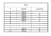
図10に、ジッタしている映像信号Sv、つまりジッタ信号Svjの特徴量を示す。図9に示した非ジッタ信号Svjnの場合と違って、ジッタ信号Svjは、フィールドv=0〜n−1において、フィールド間垂直時間差△Stf(V)は−15〜16の範囲でばらついている。ジッタ信号Svjは、例えばアナログビデオテープレコーダから出力される映像信号である。この場合、アナログビデオテープレコーダの構成よりその出力映像信号からジッタを完全になくすことは非常に困難である。
【0052】
図10に示す如く、ジッタ信号Svjにおいては、フィールドV間の周期変動は継続的にばらついている。このばらつき量dspを計測、例えば、その分散を計算すれば、ジッタ量を正確に検出できる。画質補正量の調整とは、水平系の画質を補正することでもあるので、本来は水平レートでジッタ量を計測するのが直接的であるが、以下に代表的に列挙される困難がある。
【0053】
先ず、かなりの高クロックで時間計測する必要がある。次に、計算量が膨大である。さらに、水平周期は短いので、測定精度を確保するのが非常に難しい。
このような困難さを鑑みて、本発明においては、ジッタ信号Svjのジッタ成分が積分された結果である垂直のジッタ量に基づいてジッタ測定を行う。なお、垂直のジッタ量に基づいてジッタ測定を行う場合には、現フィールドと前フィールドが同一周期になる場合や、1垂直期間で積分すればジッタが相殺されることが懸念される。
【0054】
しかしながら、現実上、アナログビデオテープレコーダにおいては、映像信号Svの現フィールドと前フィールドが同一周期になる確率は現実的にほぼ0に等しく、ジッタ量が多い場合は前フィールドとのジッタ量の差が大きくなるという事実がある。これらの事実に基づいて、本発明においては、垂直のジッタ量に基づいて正確なジッタ測定を可能にしている。以下に、図3〜図7を参照して、ジッタ測定方法を具体的に説明する。
【0055】
図3に示すメインフローチャートを参照して、本発明の実施形態にかかる補正調整器CAの主な動作について説明する。画質補正装置IQCpが組み込まれたテレビジョンセットの動作が開始すると、
ステップ#100において、先ず補正調整器CAの初期化が行われる。つまり、ジッタ検出器22において生成されるジッタ検出信号Sjdに対応するジッタ認定フラグex_jitterが0にセットされると共に、ジッタ遷移信号Sffに対応するfirst_flagが1にセットされ、さらに現フィールドVに相当する変数であるフィールドvが0にセットされ、ジッタ量信号Dspに対応する変数であるジッタ量dspが0にセットされる。
【0056】
なお、ジッタ認定フラグex_jitterが0であれば映像信号Svは非ジッタ信号Svjnであることを示し、1であれば映像信号Svはジッタ信号Svjであることを示す。first_flagが0であれば同一の映像信号Svに対して補正調整が継続して行われていることを示し、1であれば同一の映像信号Svに対して補正調整が未だ開始されていないことを示す。
【0057】
このように、画質補正装置IQCp(補正調整器CA)の動作開始時においては、映像信号Svはジッタしていないものと扱われる。それゆえ、当然、画質補正調整も開始されていない(first_flag=1)。そして、処理は次のステップ#200に進む。
【0058】
ステップ#200において、映像信号Svの垂直時間を求める垂直平均時間算出サブルーチンが実行される。なお、垂直平均時間算出サブルーチンは、垂直時間計測器21によって実行される処理であって、その詳細については、後ほど図4を参照して説明する。そして、処理は次のステップ#700に進む。
【0059】
ステップ#700において、映像信号Svのジッタ量が算出される。なお、本ステップにおけるジッタ量算出サブルーチンは、ジッタ量計測器23によって実行される処理であって、その詳細については、図7を参照して後ほど説明する。そして、処理は次のステップ#300に進む。
【0060】
ステップ#300において、ジッタ認定フラグex_jitterが1、つまり映像信号Svがジッタ信号Svjであると認定されているか否かが判断される。そしてNo、つまり映像信号Svがジッタしていないと判断される場合は、処理は次の#400に進む。
【0061】
ステップ#400において、映像信号Svがジッタしていない状態(ステップ#300でNO)からジッタしている状態になったことを確認するジッタ認定サブルーチンが実行される。つまり、本ステップにおけるジッタ認定サブルーチンは、映像信号Svが本当にジッタ信号Svjであることを認定する役割を担っている。なお、ジッタ認定サブルーチンはジッタ検出器22によって実行される処理であって、その詳細については、後ほど図5を参照して説明する。そして、処理は、上述のステップ#200に戻り垂直平均時間算出サブルーチンが実行される。
【0062】
一方、ステップ#300においてYes、映像信号Svがジッタ信号Svjであると認定されている場合は、処理はステップ#500に進む。
ステップ#500において、映像信号Svがジッタしている状態(ステップ#300でYes)からジッタしていない態になったことを確認する非ジッタ認定サブルーチンが実行される。
【0063】
つまり、本ステップにおける非ジッタ認定サブルーチンは、#400のジッタ認定サブルーチンによって一旦ジッタ信号Svjであると認定された映像信号Svが非ジッタ信号Svjnに変化していないかを監視し、認定する役割を担っている。なお、非ジッタ認定サブルーチンはジッタ検出器22によって実行される処理であって、その詳細については図6を参照して後ほど説明する。そして、処理は、次のステップ#800に進む。
【0064】
ステップ#800においては、ROM16から読み出された所定補正量SCAcを、ジッタ量計測器23から入力されるジッタ量信号Sdspおよびジッタ検出器22から出力されるジッタ遷移信号Sffに基づいて、入力されている映像信号Svのジッタ状態に応じて適正な画質補正調整量を算出する。なお、本ステップにおける画質補正調整量算出サブルーチンは、画質補正量算出器24によって実行される処理であって、その詳細については図8を参照して後ほど説明する。そして、処理は次のステップ#900に進む。
【0065】
ステップ#900においては、映像信号Svに対して適用すべき画質補正量が算出される。なお、本ステップにおける画質補正量算出サブルーチンは、画質補正量算出器24によって実行される処理であって、その詳細については図3を参照して後ほど説明する。そして処理は次のステップ#1000に進む。
【0066】
ステップ#1000において、ROM16から読み出された所定補正量SCAcをステップ#900で求めた画質補正量になるように調整して、適正化補正量SCAvを生成する。なお、適正化補正量SCAvは、適正化ノイズ低減補正量SNRv、適正化水平輪郭強調補正量SOEv、および適正化スキャン速度補正量SVMvからなる。そして、処理は上述のステップ#200に戻る。
【0067】
<#200>
以下に、図4を参照して上述のステップ#200における垂直平均時間算出サブルーチンについて説明する。
【0068】
ステップ#100における初期化処理において、フィールドvが0に、ジッタ量dspが0に、ジッタ認定フラグex_jitterが0に、first_flagが1にセットされたのちに、
ステップS201において、フィールドvが0であるか否かが判断される。Yesの場合、処理はステップS202に進む。
【0069】
ステップS202において、垂直時間Stf(v)をフィールド毎の累積値を示す変数である累積垂直時間Stf_sumが0にセットされる。これは、つまり映像信号Svに対する最初の垂直平均時間算出処理(ステップS201でYes)であるからである。そして、処理はステップS204に進む。
【0070】
一方、ステップS201においてNo、つまり映像信号Svの2番目以降のフィールドに対して垂直平均時間算出処理を行う場合には、上述のステップS202をスキップして、処理はステップS204に進む。
【0071】
ステップS204において、フィールドvが所定の値を有するloopより小さいか否かが判断される。Yes、つまり小さいと判断される場合には、処理はステップS206に進む。
【0072】
ステップS206において現フィールドの垂直時間Stf(v)が取得される。そして、処理は次のステップS208に進む。
【0073】
ステップS208において、変数Stf_sumがステップS206で取得さられた垂直期間Stf(v)だけインクリメントされる。そして、本サブルーチンを終了する。
【0074】
一方、ステップS204においてNo、つまりフィールドvがloopと同一であると判断される場合には、処理はステップS212に進む。
【0075】
ステップS212において、loopに相当するフィールドv分の垂直時間Stf(v)である累積垂直時間Stf_sumをloopで除算して平均垂直時間Stf_aveが算出される。そして、本サブルーチンを終了して、処理はステップ#700のジッタ量算出サブルーチンに進む。
【0076】
<#700>
次に、図7を参照して上述のステップ#700におけるジッタ量算出サブルーチンについて説明する。上述のステップ#200の垂直平均時間算出サブルーチンにおいて平均垂直時間Stf_aveが算出された後に、本ステップにおけるサブルーチンの実行が開始される。
【0077】
ステップS704において、フィールドvが0であるか否かが判断される。No、つまりフィールドvが映像信号Svの画質補正調整処理を受ける最初のフィールドでないと判断される場合、処理はステップS708に進む。
ステップS708において、垂直時間Stf(v)算出用の変数であるStf_buffを0にセットする。そして処理は、ステップS710に進む。
【0078】
一方、ステップS704においてYes、つまりフィールドvが映像信号Svの画質補正調整処理を受ける最初のフィールドであると判断される場合には、処理はステップS710に進む。
【0079】
ステップS710において、現フィールドの垂直時間Stf(v)が取得される。そして処理は、ステップS712に進む。
【0080】
ステップS712において、フィールドvがloopより小さいか否かが判断される。Yes、つまりフィールドvがloopより小さいと判断される場合、処理はステップS714に進む。
【0081】
ステップS714において、変数Stf_buffが(Stf(j)−Stf_ave)2 だけインクリメントされる。そして、処理は次のステップS716に進む。
ステップS716において、フィールドvが1だけインクリメントされる。そして、本サブルーチンを終了して、処理はステップ#300に進む。
【0082】
一方、ステップS712においてNo、つまりフィールドvがloopと同一であると判断される場合に、処理はステップS718に進む。
【0083】
ステップS718において、Stf_buff1/2 がジッタ量dspにセットされる。そして、処理は次のステップS720に進む。
【0084】
ステップS720において、フィールドvが0にセットされる。そして、本サブルーチンを終了して、処理はステップ#300に進む。
【0085】
<#400>
次に、図5を参照して、ステップ#400におけるジッタ認定サブルーチンについて説明する。上述のステップ#300においてNo、つまり映像信号Svは非ジッタ信号であると判断された後に、本サブルーチンの処理が開始される。
先ず、ステップS402において、現フィールドの垂直時間Stf(v)が取得される。そして、処理は次のステップS404に進む。
【0086】
ステップS404において、現フィールドの垂直時間Stf(v)から前フィールドの垂直時間Stf(v−1)を減算して、連続する2フィールド間の垂直時間差を示す変数であるフィールド間時間差tmpを算出する。そして、処理は次のステップS406に進む。
【0087】
ステップS406において、フィールド間時間差tmpの絶対値abs(tmp)が1より大きいか否かが判断される。なお、ジッタ信号のフィールド間時間差tmpの絶対値abs(tmp)が1より大きくなる傾向が大である事実に基づいて、映像信号Svがジッタしているか否かの判定を行う。判断結果がYes、つまり映像信号Svがジッタ信号であると判定される場合には、処理はステップS408に進む。
【0088】
ステップS408において、ジッタ判定カウンタCejを1だけインクリメントする。そして、処理は次のステップS410に進む。なお、映像信号Svがジッタ信号でなくても、伝送路や装置における種々の要素によって一時的にフィールド間時間差tmpの絶対値絶対値abs(tmp)が大きく検出されて、ステップS406においてジッタしていると誤判定されてしまう場合が生じる。ジッタ判定カウンタCejは、このような誤判定を防止するために、ステップS406によるジッタ信号判定の回数を検出するために設けられているものである。
【0089】
ステップS410において、ジッタ判定カウンタCejがジッタ認定基準回数Tejと同一であるか否かが判断される。ジッタ認定基準回数Tejは、ステップS406における誤判定を避けるために、所定の回数だけ連続してジッタしていると判定された場合に初めて、映像信号Svがジッタ信号Svjであると認定するための閾値である。
【0090】
つまり、ステップS406において判定基準回数Tejだけ、映像信号Svはジッタしていると判定された場合に初めて、ジッタ信号Svjと認定される。判定基準回数Tejは、3以上の任意の値を設定できる。判定基準回数Tejの値が大きい程認定精度は向上するが、通常5程度で十分実用レベルの認定精度を確保できる。本ステップにおいてNo、つまり映像信号Svがジッタ信号Svjであると認定されない場合は本サブルーチンを終了して、処理は上述のステップ#200に戻る。
【0091】
一方、本ステップS410においてYes、つまり映像信号Svはジッタ信号であると判定された場合、処理は次のステップS412に進む。
ステップS412において、ジッタ認定フラグex_jitterが1にセットされる。そして本サブルーチンを終了して、処理は上述のステップ#200に戻る。
【0092】
また、上述のステップS406においてNo、つまり映像信号Svがジッタしていないと判定される場合は、処理はステップS414に進む。
ステップS414において、判定カウンタCejはゼロにセットされる。そして、本サブルーチンを終了して、処理は上述のステップ#200に戻る。
【0093】
上記の如く各ステップ毎の動作について説明した本サブルーチンの動作について、以下に映像信号Svの状態に基づいて具体的に説明する。
補正調整器CAの起動時においては、映像信号Svは非ジッタ信号であると想定されている(#100)ので、処理はステップ#200および#300を経てステップ#400に進む。そして、ステップS402およびS404を経て、ステップS406で映像信号Svがジッタしているか判定される。
【0094】
ジッタ信号と判定されれば、ステップS408、S410を経て、またステップ#200、#300、およびステップS402〜S408を経て、ステップS410でジッタ信号Svjと認定された後にステップS412においてジッタ認定フラグex_jitterが1にセットした後に、処理はステップ#200に戻る。そして、ステップ#200を経て、ステップ#300においてYes、つまりジッタ認定フラグex_jitter=1であると判定されて処理はステップ#500に進む。
【0095】
<#500>
次に、図6を参照して上述のステップ#500における非ジッタ認定サブルーチンについて説明する。上述のステップ#300においてYes、つまりステップ#400のジッタ認定サブルーチンによってジッタ信号Svjが認定された後に本ステップにおけるサブルーチンの実行が開始される。
【0096】
ステップS502において、画質補正装置IQCpに入力されている映像信号Svが途切れているか否かを判断する。映像信号Svの途切れは、水平同期信号Hsync或いは垂直同期信号Vsyncの入力が無くなった状態、若しくは画質補正装置IQCpに連動して設けられた映像信号切替ボタン等によって、映像信号Svから別の映像信号に切り替えられた様態をもって判断される。No、つまり映像信号Svが継続して入力されていると判断される場合、処理ステップS504に進む。
【0097】
ステップS504において、現フィールドの垂直時間Stf(v)が取得される。そして、処理は次のステップS506に進む。
【0098】
ステップS506において、フィールド間時間差tmpを算出する。そして、処理は次のステップS508に進む。
【0099】
ステップS508において、フィールド間時間差tmpの絶対値abs(tmp)が1以下か否かが判断される。Yes、つまり映像信号Svが非ジッタ信号であると判定される場合には、処理はステップS510に進む。
【0100】
ステップS510において、非ジッタ判定カウンタCnjを1だけインクリメントする。そして、処理は次のステップS512に進む。なお、映像信号Svがジッタ信号であっても、伝送路や装置における種々の要素によって一時的にフィールド間時間差tmpの絶対値が小さく検出されて、ステップS508においてジッタ信号でないと誤判定されてしまう場合が生じる。非ジッタ判定カウンタCnjは、このような誤判定を防止するために、ステップS508による非ジッタ信号判定の回数を検出するために設けられている。
【0101】
ステップS512において、非ジッタ判定カウンタCnjが非ジッタ認定基準回数Tnjと同一であるか否かが判断される。非ジッタ認定基準回数Tnjは、ステップS510における誤判定を避けるために、所定の回数だけ連続して非ジッタ信号と判定された場合に初めて、映像信号Svが非ジッタ信号であると認定するための閾値である。非ジッタ認定基準回数Tnjは、3以上の任意の値を設定できる。非ジッタ認定基準回数Tnjの値が大きい程認定精度を向上するが、通常5程度で十分実用レベルの認定精度を確保できる。
【0102】
本ステップにおいてNo、つまり映像信号Svが非ジッタ信号Svjnであると認定されない場合は本サブルーチンを終了する。一方、本ステップにおいてYes、つまり映像信号Svが非ジッタ信号Svjnであると認定された場合、処理はステップS514に進む。
【0103】
ステップS514において、ジッタ認定フラグex_jitterが0にセットされると共に、first_flagが1にセットされた後、本サブルーチンを終了する。そして、処理は#800の画質補正調整量算出サブルーチンに進む。
【0104】
また、上述のステップS502においてYes、つまり映像信号Svが途切れたと判断される場合には、処理は前述のステップS504〜S510をスキップして、ステップS514に進む。これは、映像信号Svが途切れていれば、本発明の目的である画質補正自体不要であるからである。
【0105】
さらに、ステップS508においてNo、つまり映像信号Svはジッタ信号であると判定された場合、処理は次のステップS516に進む。
ステップS516において、非ジッタ判定カウンタCnjがゼロにセットされた後、本サブルーチンが終了される。そして、処理は上述のステップ#800の画質補正調整量算出サブルーチンに進む。
【0106】
上記の如く各ステップ毎の動作について説明した本サブルーチンの動作について、以下に映像信号Svの状態に基づいて具体的に説明する。上述のステップ#100〜#400における処理の後、ジッタ信号Svjであると認定された映像信号Svに関して、ステップS502、S504、およびS506を経て、ステップS508で映像信号Svのジッタが解消していないか、つまり非ジッタ信号であるか否かが判定される。
【0107】
非ジッタ信号と判定されれば、ステップS510を経てステップS512で非ジッタ判定回数Cnjが非ジッタ認定基準回数Tnjに到達していなければ、ジッタ認定フラグex_jitter=1の状態でステップ#800の非ジッタ認定サブルーチンに進む。そして、処理はステップ#500、#800、#900、#1000、#200、#700、および#300を経て、ステップ#500に戻る。そして、ジッタ信号Svjから非ジッタ信号Svjnに変わったと判断(ステップS512においてYes)された後、ステップS514でジッタ認定フラグex_jitter=0およびfirst_flag=1(ステップS514)の状態で、処理はステップ#800に進む。
【0108】
<#800>
次に、図8を参照して上述のステップ#800における画質補正調整量算出サブルーチンについて説明する。#500の非ジッタ認定サブルーチンを経て、映像信号Svのジッタ状態が検出された後に以下の処理が実行される。
ステップS802において、ジッタ認定フラグex_jitterが0であるか否かが判断される。Yes、つまり#500において非ジッタ信号Svjnであると識別されている場合には、処理はステップS804に進む。
【0109】
ステップS804において、ステップ#700(S718)において求められたジッタ量dspが取得される。そして処理はステップS806に進む。
ステップS806において、first_flagが0であるか否かが判断される。Yes、現映像信号Svはジッタ信号Svjから非ジッタ信号Svjnに変わったばかりでなく、継続的に画質補正調整処理を受けている場合には、処理はステップS807に進む。
【0110】
ステップS807において、前フィールドのジッタであるdsp_buffから現フィールドのジッタ量dspを減じてフィールド間ジッタ量差△dspが求められる。そして、処理はステップS808に進む。
ステップS808において、フィールド間ジッタ量差△dspが0より大きいか否かが判断される。Yes、つまりジッタ量が大きくなっていると見なされる場合は、処理はステップS810に進む。
【0111】
ステップS810において、画質補正量を調整するための調整変数xが1だけインクリメントされる。そして、処理は次のステップS811に進む。これは、現在の調整を映像信号Svのジッタ変動に対応させるための処理である。つまり、映像信号Svのジッタが前フィールドに比べて増大しているので、現在の画質補正調整量yでは不適切(調整不足)であると判断して、調整変数xをインクリメントして調整を強化するものである。そして、処理はステップS811に進む。
【0112】
ステップS811において、dsp_buffが現フィールドのジッタ量dspとしてセットされる。そして、処理はステップS811に進む。
ステップS812において、調整変数x+1の関数として規定される値f(x+1)を画質補正調整量yとする。つまり、ROM16から読み出された所定補正量SCAcの値を、f(x+1)値で調整したものを適正化補正量SCAvとして出力する。そして、本サブルーチンを終了して、処理はステップ#900に進む。
【0113】
なお、上述のステップS808においてNo、つまり現フィールドにおけるジッタ量が前フィールドに比べて大きくなっていないと見なされる場合は、処理はステップS814に進む。
【0114】
ステップS814において、フィールド間ジッタ量差△dspが0であるか否かが判断される。Yes、つまりフィールド間でジッタ量に変化がないと見なされる場合、処理は上述のステップS812に進む。
【0115】
ステップS812において、現在の補正変数xで規定される値f(x)をそのまま画質補正調整量yとして求める。つまり、ROM16から読み出された所定補正量SCAcの値を、f(x)値で調整したものを適正化補正量SCAvとして出力する。
【0116】
なお、ステップS814においてNo、つまり映像信号Svのジッタが減少傾向にある場合、処理はステップS816に進む。
ステップS816において、調整変数xが1だけデクリメントされる。そして、処理はステップS814に進む。これは、映像信号Svのジッタが前フィールド時に比べて減少しているので、現在の画質補正調整量yでは不適切(調整過剰)であると判断して、調整変数xをデクリメントして補正調整を弱めるものである。
【0117】
ステップS812において、補正変数x−1の関数として規定される値f(x−1)を画質補正調整量yとする。つまり、ROM16から読み出された所定補正量SCAcの値を、f(x−1)値で調整したものを適正化補正量SCAvとして出力する。
【0118】
一方、上述のステップS806においてNo、つまり映像信号Svは非ジッタ信号Svjnからジッタ信号Svjに変わったと認定されて、補正調整が初めて開始される場合、処理はステップS818に進む。
【0119】
ステップS818において、調整変数xとしてジッタ量dspが設定されると共に、first_flagが0に設定される。これは、first_flagが0でない(S806)ので、映像信号Svに対して初めて補正調整を開始するに当たって、基準となる調整変数xにその時点のジッタ量dspを設置することによって、最初に設定する画質補正調整量yを適正なものにするものである。そして、first_flagを0に設定し直して、以降の調整はジッタ量dspで規定される調整変数xを基準として画質補正調整量yを調整する(S810、S816、およびS812)ものである。
【0120】
さらに、上述のステップS802においてNo、つまり映像信号Svは非ジッタであると認定されている場合は、処理はステップS820に進む。
ステップS820において、画質補正調整量yを1に設定する。つまりROM16から読み出された所定補正量SCAcの値をそのまま適正化補正量SCAvとして出力する。
【0121】
次に、図11および図12を参照して、画質補正調整方法を具体的に説明する。画質補正は2つのカテゴリーに大別できる。第1は、輝度変化のある部分(エッジを強調することで再生画像の先鋭度を上げる作用を有するもの。輪郭補正、速度変調などが含まれる。第2は、輝度変化のごく小さいところやランダムな高周波成分を取り除くことで再生画像を落ち着かせる作用を有するもの。NR(ノイズリダクション)、コアリングなどが含まれる。
【0122】
画質補正は再生画像をより良くするが、映像信号がジッタしている場合には、これらの補正をジッタしていない信号と同様に一律に適応すれば、画質改善されないばかりかかえって悪化させてしまう。そこで、本発明においては、映像信号Svがジッタしているか否か、つまりジッタ信号Svjか非ジッタ信号Svjnであるかを認定して、認定結果に応じて自動的に画質補正量を調整(制御)するものである。
【0123】
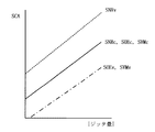
しかしながら、画質の善し悪しの判断は、視聴者にゆだねられる部分も大きい。そこで、視聴者による画質調整(制御)幅を確保するために、図11および図12に示す次の二つの方法が用意される。両図において、縦軸は画質補正量SCAを示し、横軸は視聴者による調整(制御)が基づくジッタ量の絶対値を示し、実線は画質補正量SCA(SNR、SOE、およびSVM)を示し、点線は適正化ノイズ低減補正量SNRvを示し、一点鎖線は適正化水平輪郭強調補正量SOEvおよび映像信号Svmを示す。
【0124】
図11においては、画質補正の基本量である所定補正量SCAc(SNRc、SOEc、およびSVMc)の傾きをジッタ量に応じて調整する方法が例示されている。そして、適正化ノイズ低減補正量SNRv(点線)は、ノイズ低減補正量SNRcをノイズ量に応じて正側に調整して得られる。一方、適正化水平輪郭強調補正量SOEvおよび適正化スキャン速度補正量SVMvは、水平輪郭強調補正量SOEcおよびスキャン速度補正量SVMcをそれぞれノイズ量に応じて負側に調整して得られる。この場合、視聴者は自分の好みに応じて、調整された傾きをさらに調整できる。
【0125】
図12においては、画質補正の基本量である所定補正量SCAc(SNRc、SOEc、およびSVMc)を一律増減させて調整する方法が例示されている。図11に例示した方法と同様に、適正化ノイズ低減補正量SNRv(点線)は、ノイズ量に応じて正側に調整される。一方、適正化水平輪郭強調補正量SOEvおよび適正化スキャン速度補正量SVMvは、ノイズ量に応じて負側に調整される。この場合、視聴者は自分の好みに応じて、一律に調整されたをさらに増減して調整できる。
【0126】
<#900>
図13を参照して、ステップ#900の画質補正量算出サブルーチンの考え方を説明する。同図において、縦軸は画質補正量y=f(x)、横軸はジッタ量dsp、そして実線はジッタ量dspと画質補正量f(x)の関係を示すが、直線である必要はなく所定の曲率で規定される曲線であっても良い。同図は、図13に示した基本補正量に対して傾きを調整する方法の例である。
【0127】
<#1000>
図14を参照して、ステップ#1000の画質補正パラメータ生成サブルーチンにおける考え方を説明する。同図において、縦軸は補正量SCA(SNR、SOE、およびSVM)、横軸はジッタ量dsp、点線は適正化ノイズ低減補正量SNRv、そして一点鎖線は適正化水平輪郭強調補正量SOEvおよび適正化スキャン速度補正量SVMvを示す。
【0128】
上述のように適正化ノイズ低減補正量SNRvは、ジッタに応じて正側に調整されるともに、その値はノイズ低減補正量SNRcに画質補正調整量y=f(x)を乗じて求める。適正化水平輪郭強調補正量SOEvおよび適正化スキャン速度補正量SVMvは共に、ジッタに応じて負側に調整されると共に、それらの値はそれぞれ水平輪郭強調補正量SOEcおよび適正化スキャン速度補正量SVMvに画質補正調整量y=f(x)を乗じて求める。
【0129】
(変形例)
以下に、図15〜図21を参照して、本発明の実施形態にかかる補正調整器CAの変形例について説明する。本変形例にかかる補正調整器CAの構成は図2に示したのと同じ構成を有しているが、その動作が異なる。
先ず、図15に示すメインフローチャートを参照して、本変形例にかかる補正調整器CAの主な動作について説明する。本変形例においては、主に実施形態におけるステップ#200の垂直平均時間サブルーチン、ステップ#700のジッタ量算出サブルーチン、およびステップ#800の画質補正調整量算出サブルーチンを簡易化された手法で実現するものである。そのため、図3に示すステップ#100、#200、#400、#500、#900が、図15に示すように本変形例においては、それぞれ#100R、S206R、#400R、#500R、および#900Rに置き換えられている。また、本変形例においては、実施形態における#700は削除されている。
【0130】
さらに、実施形態におけるステップ#800の画質調整量算出サブルーチンとステップ#900の画質補正量算出サブルーチンは、本変形例においては、ステップ#1100の画質調整量算出/画質補正量算出サブルーチンに置き換えられている。
【0131】
以下、図15を参照して、本実施形態にかかる補正調整器CAの主な動作を簡単に説明した後、図11、図12、および図13を参照して個々のステップにおける動作について説明する。
画質補正装置IQCpが組み込まれたテレビジョンセットの動作が開始すると、
ステップ#100Rにおいて、先ず補正調整器CAの初期化が行われる。つまり、ジッタ認定フラグex_jitterが0にセットされると共に、first_flagが1にセットされ、フィールドvが0にセットされ、画質補正調整量yが1にセットされる。
【0132】
このように、画質補正装置IQCp(補正調整器CA)の動作開始時においては、実施形態におけるのと同様に、映像信号Svはジッタしていなく、画質補正調整も開始されていないものとして扱われる。ただし、ROM16から読み出された所定補正量SCAcをそのまま適正化補正量SCAvとして設定(画質補正調整量y=1)される。そして、処理は次のステップS206に進む。
【0133】
ステップS206において、前述のS206と同様に垂直時間Stf(v)が取得される。そして、処理はステップ#300において、映像信号Svがジッタ信号Svjであると認定されていないと判断される場合、処理は次の#400Rに進む。ジッタ信号Svjであると認定されている場合、処理はステップ#500Rに進む。
【0134】
図16にステップ#400Rの詳細フローチャートを示す。本実施形態にかかるサブルーチンは、垂直時間Stf(v)を取得するステップS402が削除されている点を除いては、図5を参照して既に説明した実施形態におけるジッタ認識サブルーチンと同様であるので説明を省く。
【0135】
図17にステップ#500Rの詳細フローチャートを示す。本実施形態にかかるサブルーチンは、垂直時間Stf(v)を取得するステップS504が削除されている点を除いては、図6を参照して既に説明したジッタ認識サブルーチンと同様であるので、説明を省く。
【0136】
<#1100>
以下に、図20および図21を参照して、ステップ#1100におけるジッタ量算出/画質補正調整量算出サブルーチンにおける処理の概念を説明する。
同処理は、上述の本発明の実施形態にかかるジッタ量dspおよび補正量の計算はコンピュータに対する負荷が大きいので、その代替策として提案されるものである。両図において、縦軸は度数を示し、そして横軸はスタックを示している。スタック(stk)とは、前フィールド(v−1)と現フィールド(v)との垂直時間差(CLK数差)△Tfであるが、フィールド間垂直時間差△Stf(v)であっても差し支えない。
【0137】
本例においては、フィールド間時間差△Tfが0−1、2−4、5−7、8−10、11−13、14−16、17ー19、そして20以上である8つのスタックStkが用意されているが、スタックStkの数およびフィールド間時間差△Tfは補正調整効果を考慮して適宜決定する。それぞれのスタックStkはフィールド間時間差△Tfの値に応じて、1、2、3、4、5、6、7、および8のスタック番号(Stk No.)が与えられている。以降、各スタックはstk(k)として識別する。なお、kはスタック番号を表す変数である。
【0138】
本変形例においては、ジッタ量算出/画質補正調整量算出は以下の段階を経て求められる。先ず、所定補正量SCAcを変化させたい段階と同数のスタックStk(k)を準備する。次に、フィールド間時間差△Tfgの値に対応するスタックStk(k)に、その出現度数を積んで、ジッタ量のヒストグラムを求める。nフィールド中で出現度数が閾値th_Aを超えたスタックの内、フィールド間時間差△Tfgが最大のものを選択し、ROMテーブルから補正値を与える。なお、補正結果が滑らかになるように、スタックStkおよび調整値を適切に設定する。
【0139】
これを図21を参照して説明すると、閾値th_Aを超えているのはStk(4)、Stk(5)、およびStk(7)である。これら3つのスタックStkのうちフィールド間時間差△Tfが最大であるのでStk(7)に対する補正値がROMテーブルから読み出される。
【0140】
図18および図19を参照して、#1100のジッタ量算出/画質補正調整量算出サブルーチンについて説明する。
先ず、ステップS2において、フィールドvが0であるか否かが判断される。Yes、つまり映像信号Svの最初のフィールドであると判断された場合には、処理はステップS4に進む。
【0141】
ステップS4において、スタック番号を表す変数であるkが0にセットされる。そして、処理は次のステップS6に進む。
ステップS6において、kが1だけインクリメントされる。そして、処理は次のステップS8に進む。
ステップS8において、stk(k)が0にセットされる。そして、処理は次のステップS10に進む。
【0142】
ステップS10において、kがnより小さいか否かが判断される。Yesと判断される場合は、処理はステップS6に戻る。そして、ステップS8を経て、k=nと判断されるまで、ステップS6、S8、およびS10のループ処理を繰り返す。一方、本ステップにおいてNoと判断される場合は、処理は、上述のループを抜け出して次のステップS12に進む。
【0143】
一方、ステップS2においてNo、つまり映像信号Svに対して継続的に処理されていると判断される場合は、上述のステップS4〜S10をスキップして、処理はステップS12に進む。
【0144】
ステップS12おいては、フィールドvがloopより小さいか否かが判断される。Yesの場合、処理はステップS14に進む。
ステップS14において、現フィールドの垂直時間Stf(v)から前フィールドの垂直時間Stf(v−1)を減じたものをdifにセットする。difは、図20および図21に示したフィールド間時間差△Tfに相当する。そして、処理はステップS16に進む。
【0145】
ステップS16においては、difが0以上且つth(0)より小さいか否かが判断される。Yesの場合は、処理はステップS18に進む。
ステップS18においては、stk(0)が1だけインクリメントされる。このステップを繰り返すことで、スタックStk(0)における度数が求めれる。そして処理はステップS30に進む。
【0146】
一方、ステップS16においてNoの場合には、処理は次のスタックStk(1)の度数を調べるステップS20に進む。
ステップS20においては、difがth(0)以上且つth(1)より小さいか否かが判断される。Yesの場合は、処理はステップS22に進む。
ステップS22においては、stk(1)が1だけインクリメントされる。このステップを繰り返すことで、スタックStk(1)における度数が求めれる。そして処理はステップS30に進む。
【0147】
一方、ステップS20においてNoの場合には、処理はスタックStk(n−1)の度数を調べるステップS24に進む。
ステップS24においては、difがth(n−1)であるか否かが判断される。Yesの場合、処理はステップS26に進む。
ステップS26においては、stk(n−1)が1だけインクリメントされる。そして処理はステップS30に進む。
【0148】
一方、ステップS24においてNoの場合には、処理は次のスタックStk(n)の度数を調べるステップS28に進む。
ステップS28においては、stk(n)が1だけインクリメントされる。そして処理はステップS30に進む。なお、図18においては紙面の都合上、nが4の場合を示しているが、より滑らかな補正調整効果を得るために適切に決められる任意の数であることは上述の通りである。なお、ステップS18、S22、S26、およびS28を経て、ジッタ量のヒストグラムが求められる。
【0149】
さらに、上述のステップS12においてNo、つまりvがloopに等しいと判断された場合、処理はステップS32に進む。
ステップS32において、ジッタ認定フラグex_jitterが0であるのか否かが判断される。No、つまり映像信号Svはジッタ信号Svjであると認定されている場合、処理はステップS34に進む。
【0150】
ステップS34においてadj_tmpが0にセットされる。そして、処理は次のステップS36に進む。
ステップS36において、kが0にセットされる。そして、処理は次のステップS38に進む。
【0151】
ステップS38において、kがnより小さいか否かが判断される。Yesの場合、処理はステップS40に進む。
ステップS40において、stk(k)≧th_Aであるか否かが判断される。Noの場合、処理はステップS42に進む。
ステップS42において、adj_tmpがkにセットされる。そして、処理はステップS44に進む。
【0152】
ステップS44において、kが1だけインクリメントされる。そして、処理はステップS38に戻る。
一方、ステップS40においてYesの場合は、処理はステップS42をスキップしてステップS44に進む。
また、ステップS38においてNo、つまりk=nの場合、処理はステップS46に進む。
【0153】
ステップS46において、first_flagが1であるのか否かが判断される。Noの場合、処理はステップS48に進む。
ステップS48において、adj_tmpから調整変数xを減じた値が0より大きいか否かが判断される。Yesの場合、処理はステップS50に進む。
ステップS50において、調整変数xが1だけインクリメントされる。そして、処理はステップS58に進む。
【0154】
ステップS58において、Sadj(x)がyとして設定される。そして、処理はステップS62に進む。
ステップS62において、フィールドvが0にセットされる。そして、本サブルーチンを終了する。
【0155】
一方ステップS48においてNoの場合は、処理はステップS52に進む。ステップS52において、adj_tmpが調整変数xと等しいか否かが判断される。Yesの場合、処理はステップS54に進む。
【0156】
ステップS54においては、調整変数xが1だけデクリメントされる。そして、処理はステップS58に進む。
なお、ステップS46においてNoと判断される場合、処理はステップS56に進む。
【0157】
ステップS56においては、調整変数xの値としてadj_tmpが設定されると共に、first_flagは0にセットされる。そして処理はステップS58に進む。
一方、ステップS32においてYes、つまり映像信号Svは非ジッタ信号Svjnと認定されている場合、処理はステップS60に進む。
ステップS60において、画質補正調整量yは1にセットされる。
【0158】
そして、本サブルーチンにおいて求められた画質補正調整量yに基づいて、ステップ#900Rおよび#1000において上述の如く画質補正調整が行われる。なお、ステップ#900Rは上述のステップ#900における処理と基本的に同一である。
以上のように本発明によれば、ジッタ成分を持った映像信号を自動的に検出し、そのジッタ量を計測し、その量に応じて水平輪郭補正量、速度変調量、ノイズ低減量を適応的に加減させることで、入力信号の状態に応じ最適な画質補正を行う放送受信装置を構成する事が可能になる。
【図面の簡単な説明】
【図1】テレビジョンセットに用いられている、本発明にかかる画像補正装置の構成を示すブロック図である。
【図2】図1に示す補正調整器の構成を示すブロック図である。
【図3】図2に示す補正調整器の主な動作を示すフローチャートである。
【図4】図3に示す垂直平均時間算出サブルーチンの詳細な動作を示すフローチャートである。
【図5】図3に示すジッタ認定サブルーチンの詳細な動作を示すフローチャートである。
【図6】図3に示す非ジッタ認定サブルーチンの詳細な動作を示すフローチャートである。
【図7】図3に示すジッタ量算出サブルーチンの詳細な動作を示すフローチャートである。
【図8】図3に示す画質補正調整量算出サブルーチンの詳細な動作を示すフローチャートである。
【図9】非ジッタ信号の特徴量を示す説明図である。
【図10】ジッタ信号の特徴量を示す説明図である。
【図11】所定補正量の傾きをジッタ量に応じて調整する方法の説明図である。
【図12】所定補正量を一律増減させて調整する方法の説明図である。
【図13】図3に示す画質補正量算出サブルーチンの説明図である。
【図14】図3に示す画質補正パラメータ生成サブルーチンの説明図である。
【図15】本発明の実施形態の変形例にかかる補正調整器の主な動作を示すフローチャートである。
【図16】図15に示すジッタ認定サブルーチンの詳細な動作を示すフローチャートである。
【図17】図15に示す非ジッタ認定サブルーチンの詳細な動作を示すフローチャートである。
【図18】図15に示したジッタ量算出/画質補正調整量算出サブルーチンの詳細な動作を示すフローチャートの前半部である。
【図19】図15に示したジッタ量算出/画質補正調整量算出サブルーチンの詳細な動作を示すフローチャートの後半部である。
【図20】図15に示したジッタ量算出/画質補正調整量算出サブルーチンの説明図である。
【図21】図15に示したジッタ量算出/画質補正調整量算出サブルーチンの説明図である。
【図22】テレビジョンセットに用いられている、従来の画像補正装置の構成を示すブロック図である。
【符号の説明】
SPp 信号処理システム
IQCp、IQCc 画質補正装置
4 同期分離器
5 信号処理器
6 スキャン速度変調駆動器
7 CRT駆動器
8 偏向器
9 画像表示器
11 スキャン速度変調信号生成器
12 水平輪郭強調器
13 ノイズ低減器
14 マルチプレクサ
15 バスインターフェース
16 ROM
CA 補正調整器
21 垂直時間計測器
22 ジッタ検出器
23 ジッタ量計測器
24 画質補正量算出器
100p 制御器[0001]
BACKGROUND OF THE INVENTION
The present invention relates to an image quality correction apparatus that performs various processing on a video signal and corrects the quality of an image reproduced from the video signal. More specifically, the present invention relates to an image signal jitter amount that greatly affects the image quality. The present invention relates to an image quality correction apparatus that corrects image quality with an appropriate correction amount according to the above.
[0002]
[Prior art]
FIG. 22 shows a conventional image correction apparatus used for an analog video signal Sv which is a source of an image displayed on an image display device used in a television set represented by an LCD or CRT. As shown in the figure, in the television set, the signal processing system SPc performs various processes on the video signal Sv and is necessary for displaying an image on the image display 9 (CRT in this example). A scan speed modulation signal VSCc, an image signal Si, and a horizontal synchronization signal Hsync and a vertical synchronization signal Vsync representing information corresponding to the characteristics of the
[0003]
Based on the scan speed modulation signal VSCc, the scan
[0004]
The signal processing system SPc includes a
The image quality correction apparatus IQCc performs image quality correction processing on the video signal Sv based on the horizontal synchronization signal Hsync and the vertical synchronization signal Vsync to generate the image quality corrected video signal SIQc and also generates the scan speed modulation signal VSCc. The
[0005]
The image quality correction apparatus IQCc includes a scan speed
[0006]
The scan speed
[0007]
Even if the quality of the video signal Sv is constant, if the video carried by the video signal Sv is displayed on the
[0008]
Each predetermined correction amount SCAc is stored in the
[0009]
Specifically, the predetermined correction amount SCAc includes a scan speed correction amount SVMc that is a predetermined correction amount with respect to the scan speed VSC determined by the scan speed
[0010]
As described above, the
[0011]
Similar to the
The
[0012]
[Problems to be solved by the invention]
As described above, in the conventional image quality correction apparatus IQCc, scanning speed modulation, horizontal contour enhancement amount, and noise reduction are performed on the video signal Sv by a predetermined amount in consideration of the influence of the physical characteristics of the television set. Correction is being performed. That is, the correction amount by the image quality correction device IQCc is always constant regardless of the change in the quality of the video signal Sv.
[0013]
However, the quality of the video signal Sv changes with time. When the video signal Sv is jittered, the image-quality corrected video signal SIQc and the scan speed modulation signal VSCc output from the image quality correction device IQCc also cause jitter. Therefore, since the amount of jitter of the video reproduced on the
[0014]
For example, if a horizontal edge enhancement process that strongly edge-enhances the video signal Sv having jitter, the horizontal edge enhancement signal itself is also jittered. Therefore, the glare of the edge portion is emphasized, and the image quality correction process is performed on the reproduced image. Jitter is emphasized. To prevent this, the edge-enhanced image quality correction amount may be reduced and the noise removal type image quality correction amount increased in accordance with the jitter amount of the video signal Sv.
[0015]
That is, in order to prevent or improve the quality degradation of the video image due to the quality (jitter) of the video signal Sv, the scan speed
[0016]
For this purpose, it is essential to be able to accurately detect the presence / absence of jitter and the amount of jitter in the video signal Sv. However, there has not been provided means for accurately detecting the presence or absence and the amount of jitter of an input video signal Sv that is incorporated in an image display device such as a conventional television set.
SUMMARY OF THE INVENTION Therefore, the present invention has been made to solve the above-mentioned problems, and it is a first object of the present invention to provide a video signal jitter detection apparatus capable of accurately detecting the presence or absence and the amount of jitter of a video signal. And further providing an image quality correction device for correcting the image quality of the reproduced image by adaptively changing the image quality correction amount when the video signal is reproduced according to the jitter amount of the detected video signal in the jitter detection device. The second purpose.
[0017]
[Means for Solving the Problems and Effects of the Invention]
In order to solve the above problems, a first invention is a jitter detection device for detecting jitter of a video signal,
A vertical time measuring device for measuring a vertical time of one field of a video signal to generate a vertical time signal;
A jitter determiner that determines whether the video signal is jittered based on the vertical time signal and generates a jitter determination signal;
A jitter determination counter for generating a jitter determination counter signal by counting the number of times that the video signal is continuously determined to be jitter based on the jitter determination signal;
A jitter qualifier that certifies the video signal as a jitter signal when it is determined that the video signal is continuously jittered for the first predetermined number of times based on the jitter determination counter signal;
A non-jitter determination counter for generating a non-jitter determination counter signal by counting the number of times that the video signal is continuously determined to be non-jitter based on the jitter determination signal;
A non-jitter qualifier that certifies the video signal as a non-jitter signal when it is determined that the video signal is not continuously jittered a second predetermined number of times based on the non-jitter determination counter signal;,
Jitter amount calculator that calculates vertical time dispersion value sequentiallyWith.
[0018]
As described above, in the first invention, it is possible to accurately detect the jitter state and the jitter amount of the video signal by eliminating the influence of the disturbance factors such as the video signal and the noise component on the television apparatus side.
[0019]
In a second aspect based on the first aspect, the jitter determiner is
When the absolute value of the difference between the vertical time Stf of the current field and the vertical time Stf of the previous field is greater than 1, it is determined that the video signal is jittered;
When the absolute value is smaller than 1, it is determined that the video signal is not jittered.
[0021]
First3The present invention is an image quality correction device for correcting the image quality of a video signal in accordance with the jitter amount of the video signal,
A noise reducer that reduces video signal noise based on a predetermined noise reduction correction amount;
A horizontal contour enhancer that enhances the horizontal contour of the video signal based on a predetermined horizontal contour enhancement correction amount;
Comprising at least one of a scan speed modulator for enhancing a specific portion of the video signal based on a predetermined scan speed modulation amount;
An image quality correction adjuster that increases the noise reduction correction amount by a predetermined adjustment value, reduces the horizontal outline enhancement correction amount by the adjustment value, and decreases the scan speed modulation amount by the adjustment value according to the jitter amount.When,
A vertical time measuring device for measuring a vertical time of one field of a video signal to generate a vertical time signal;
A jitter determiner that determines whether the video signal is jittered based on the vertical time signal and generates a jitter determination signal;
A jitter determination counter for generating a jitter determination counter signal by counting the number of times that the video signal is continuously determined to be jitter based on the jitter determination signal;
A jitter qualifier that certifies the video signal as a jitter signal when it is determined that the video signal is continuously jittered for the first predetermined number of times based on the jitter determination counter signal;
A non-jitter determination counter for generating a non-jitter determination counter signal by counting the number of times that the video signal is continuously determined to be non-jitter based on the jitter determination signal;
A jitter detection apparatus comprising: a non-jitter qualifier that certifies a video signal as a non-jitter signal when it is determined that the video signal is not continuously jittered a second predetermined number of times based on the non-jitter determination counter signal And
The image quality correction adjuster is characterized by dynamically adjusting at least one of a noise reduction correction amount, a horizontal contour emphasis correction amount, and a scan speed modulation amount while sequentially calculating a vertical time dispersion value.
[0022]
As above,3In this invention, it is possible to perform image quality correction adjusted appropriately according to the jitter state of the video signal.
[0025]
First4The invention of the3In the invention, the image quality correction adjuster generates a histogram having an appearance frequency with respect to a jitter amount.Further equipped,
The image quality correction adjusterA feature is that at least one of a noise reduction correction amount, a horizontal contour emphasis correction amount, and a scan speed modulation amount is adjusted by a predetermined adjustment amount that is equal to or greater than a predetermined threshold in appearance frequency and corresponding to the jitter amount. To do.
[0026]
First5The invention of the3In the present invention, immediately after the video signal changes from the non-jitter signal to the jitter signal, the jitter amount of the current field is used as the adjustment value.
[0027]
First6The invention of the3In the invention, an adjustment suppressor is provided that cancels at least one adjustment of a noise reduction correction amount, a horizontal contour emphasis correction amount, and a scan speed modulation amount when the video signal changes from a jitter signal to a non-jitter signal.
[0028]
DETAILED DESCRIPTION OF THE INVENTION
First, an image quality correction apparatus according to an embodiment of the present invention will be described with reference to FIGS. Thereafter, an image quality correction apparatus according to a modification of the embodiment of the present invention will be described in detail with reference to FIGS.
[0029]
Before specifically describing the embodiment, the basic concept of the image quality correction apparatus according to the present invention will be described first. As described above, in an image display apparatus typified by a television set, the quality of an image displayed on the image display is roughly divided by the quality of the video signal and the physical characteristics of the television set. The quality of the video signal is jitter and noise, and the physical characteristics of the television set are the jitter response and frequency characteristics of the signal processing system, and the focus performance and gamma characteristics of the image display.
[0030]
In general, in order to improve the quality of an image displayed on an image display, horizontal contour emphasis on a video signal, modulation on a change in luminance signal of a raster scan speed on an image display (hereinafter referred to as “scan speed modulation”). And noise reduction processing for reducing the influence of noise components of the video signal. For a jittered video signal, horizontal edge enhancement and scan speed modulation further degrade reproduced image quality and must be suppressed. On the other hand, noise reduction does not need to be suppressed because it improves the reproduced image.
[0031]
That is, if the amount of jitter of the video signal is increased, it is only necessary to promote the reduction of noise while suppressing the enhancement of horizontal contour enhancement and scan speed modulation. On the other hand, if the amount of jitter of the video signal is reduced, horizontal contour enhancement and scan speed modulation may be promoted to reduce noise reduction. As described above, according to the present invention, by appropriately adjusting the horizontal contour emphasis, the scan speed modulation, and the noise reduction amount according to the jitter amount of the video signal, it is possible to secure the reproduced image quality by the image display device. Is.
[0032]
(Embodiment)
FIG. 1 shows a state in which an image correction apparatus according to an embodiment of the present invention is used in a television set represented by an LCD or CRT. As shown in the figure, in the television set, the signal processing system SPp performs various processes on the video signal Sv and is necessary for displaying an image on the image display 9 (CRT in this example). A raster scan speed modulation signal VSCv, an image signal Si, and a horizontal synchronization signal Hsync and a vertical synchronization signal Vsync representing information corresponding to the characteristics of the
[0033]
Based on the scan speed modulation signal VSCv, the scan
[0034]
The signal processing system SPp includes a
[0035]
The image quality correction device IQCp performs image quality correction processing on the video signal Sv based on the horizontal synchronization signal Hsync and the vertical synchronization signal Vsync to generate an image quality corrected video signal SIQv, and also generates a scan speed modulation signal VSCv. The
[0036]
The image quality correction device IQCp includes a scan speed
[0037]
The
[0038]
The correction adjuster CA measures the jitter amount of the video signal Sv based on the vertical synchronization signal Vsync extracted by the
[0039]
Specifically, the optimization correction amount SCAv includes an optimization scan speed correction amount SVMv that is a correction amount for adjusting a predetermined correction amount SVM with respect to the scan speed VSC determined by the scan speed
[0040]
The scan speed
Similarly, the
[0041]
The
[0042]
Similar to the
[0043]
The
[0044]
The configuration and operation of the correction adjuster CA will be described below with reference to FIG. As shown in FIG. 2, the correction adjuster CA includes a vertical
The vertical
[0045]
The
[0046]
The jitter
The image quality
[0047]
Next, with reference to FIG. 9 and FIG. 10, the feature amount for determining the jitter / non-jitter of the video signal Sv will be described. FIG. 9 shows the feature amount of the video signal Sv that is not jittered, that is, the non-jitter signal Svjn. In the figure, the field V is shown in the left column, the vertical time Stf (V) in each field is shown in the center column, and the inter-field vertical time difference ΔStf (V) is shown in the right column. The vertical time Stf (V) is the difference between the vertical time Stf (V-1) of the previous field and the vertical time Stf (V) of the current field.
[0048]
As shown in the figure, the non-jitter signal Svjn has a field vertical time difference ΔStf (V) in the range of −1, 0, 1 in the field V = 0 to n−1 (any positive integer). It will fit. Such a non-jitter signal Svjn is called a standard signal because the frequency of the color burst signal is synchronized with the horizontal frequency and the vertical frequency.
[0049]
When the horizontal and vertical periods are measured with a clock of 4 times the color burst signal (4Fsc), the horizontal period is 910 CLK and the vertical period is 910 CLK × 262.5 = 238875. When each value is expressed in hexadecimal notation, the horizontal period is represented by 38e horizontal counter value, and the vertical period is represented by 3a51b vertical counter value. In this embodiment, the clock for measuring the vertical period is a 4Fsc clock locked to a burst, and is not locked to horizontal synchronization, so that a measurement error of ± 1 CLK or less may occur. Therefore, the difference in vertical time Stf (V) from the previous field, that is, the inter-field vertical time difference ΔStf (V) is ± 2 CLK or less.
[0050]
However, since the horizontal synchronization signal Hsync and the vertical synchronization signal Vsync are generated by counting down from a stable burst signal, the probability that the inter-field vertical time difference ΔStf (V) actually becomes ± 2 CLK is almost zero. Based on this fact, when the inter-field vertical time difference ΔStf (V) is ± 1 or less, the video signal Sv is determined as the non-jitter signal Svjn. Also, although it is not a standard signal, its horizontal periodAndA signal having a constant vertical period may be regarded as a standard signal (non-jitter signal Svjn).
[0051]
FIG. 10 shows the characteristic amount of the jittered video signal Sv, that is, the jitter signal Svj. Unlike the case of the non-jitter signal Svjn shown in FIG. 9, the jitter signal Svj varies in the field v = 0 to n−1 and the inter-field vertical time difference ΔStf (V) ranges from −15 to 16. . The jitter signal Svj is a video signal output from, for example, an analog video tape recorder. In this case, it is very difficult to completely eliminate jitter from the output video signal due to the configuration of the analog video tape recorder.
[0052]
As shown in FIG. 10, in the jitter signal Svj, the period variation between the fields V continuously varies. If the variation dsp is measured, for example, the variance is calculated, the amount of jitter can be detected accurately. The adjustment of the image quality correction amount also means correcting the image quality of the horizontal system. Therefore, it is originally direct to measure the jitter amount at the horizontal rate, but there are difficulties listed below.
[0053]
First, it is necessary to measure time with a fairly high clock. Next, the amount of calculation is enormous. Further, since the horizontal period is short, it is very difficult to ensure measurement accuracy.
In view of such difficulties, in the present invention, jitter measurement is performed based on the vertical jitter amount that is the result of integrating the jitter components of the jitter signal Svj. When performing jitter measurement based on the vertical jitter amount, there is a concern that the current field and the previous field have the same period, or that the jitter is canceled if integration is performed in one vertical period.
[0054]
However, in reality, in an analog video tape recorder, the probability that the current field and the previous field of the video signal Sv have the same period is practically substantially equal to 0, and when the jitter amount is large, the difference in the jitter amount from the previous field. There is a fact that becomes larger. Based on these facts, the present invention enables accurate jitter measurement based on the vertical jitter amount. The jitter measurement method will be specifically described below with reference to FIGS.
[0055]
With reference to the main flowchart shown in FIG. 3, the main operation of the correction adjuster CA according to the embodiment of the present invention will be described. When the operation of the television set incorporating the image quality correction device IQCp starts,
In
[0056]
If the jitter certification flag ex_jitter is 0, the video signal Sv is a non-jitter signal Svjn, and if it is 1, the video signal Sv is a jitter signal Svj. If first_flag is 0, it indicates that the correction adjustment is continuously performed on the same video signal Sv. If it is 1, it indicates that the correction adjustment has not yet been started on the same video signal Sv. Show.
[0057]
Thus, at the start of the operation of the image quality correction device IQCp (correction adjuster CA), the video signal Sv is treated as not jittered. Therefore, as a matter of course, the image quality correction adjustment is not started (first_flag = 1). Then, the process proceeds to the
[0058]
In
[0059]
In
[0060]
In
[0061]
In
[0062]
On the other hand, if Yes in
In
[0063]
That is, the non-jitter qualifying subroutine in this step has a role of monitoring and certifying whether the video signal Sv once recognized as the jitter signal Svj by the # 400 jitter qualifying subroutine has changed to the non-jitter signal Svjn. I'm in charge. The non-jitter qualifying subroutine is a process executed by the
[0064]
In
[0065]
In
[0066]
In
[0067]
<# 200>
The vertical average time calculation subroutine in
[0068]
In the initialization process in
In step S201, it is determined whether or not the field v is 0. If yes, the process proceeds to step S202.
[0069]
In step S202, the accumulated vertical time Stf_sum which is a variable indicating the accumulated value of each vertical field Stf (v) is set to zero. This is because this is the first vertical average time calculation process for the video signal Sv (Yes in step S201). Then, the process proceeds to step S204.
[0070]
On the other hand, when No is determined in step S201, that is, when the vertical average time calculation process is performed on the second and subsequent fields of the video signal Sv, the process proceeds to step S204, skipping step S202 described above.
[0071]
In step S204, it is determined whether or not the field v is smaller than a loop having a predetermined value. If Yes, that is, if it is determined to be small, the process proceeds to step S206.
[0072]
In step S206, the vertical time Stf (v) of the current field isTakeIs obtained. Then, the process proceeds to the next step S208.
[0073]
In step S208, the variable Stf_sum is incremented by the vertical period Stf (v) acquired in step S206. Then, this subroutine ends.
[0074]
On the other hand, if No in step S204, that is, if field v is determined to be the same as loop, the process proceeds to step S212.
[0075]
In step S212, the average vertical time Stf_ave is calculated by dividing the accumulated vertical time Stf_sum, which is the vertical time Stf (v) for the field v corresponding to loop, by loop. Then, after completing this subroutine, the process proceeds to a jitter amount calculation subroutine of
[0076]
<# 700>
Next, the jitter amount calculation subroutine in
[0077]
In step S704, it is determined whether or not the field v is 0. If No, that is, if the field v is determined not to be the first field subjected to the image quality correction adjustment process of the video signal Sv, the process proceeds to step S708.
In step S708, Stf_buff, which is a variable for calculating the vertical time Stf (v), is set to zero. Then, the process proceeds to step S710.
[0078]
On the other hand, if YES in step S704, that is, if field v is determined to be the first field to be subjected to the image quality correction adjustment process of video signal Sv, the process proceeds to step S710.
[0079]
In step S710, the vertical time Stf (v) of the current field is acquired. Then, the process proceeds to step S712.
[0080]
In step S712, it is determined whether the field v is smaller than loop. If Yes, that is, if it is determined that the field v is smaller than loop, the process proceeds to step S714.
[0081]
In step S714, the variable Stf_buff is (Stf (j) −Stf_ave).2 Is incremented only by Then, the process proceeds to the next step S716.
In step S716, the field v is incremented by 1. Then, after completing this subroutine, the process proceeds to step # 300.
[0082]
On the other hand, if NO in step S712, that is, if it is determined that the field v is the same as the loop, the process proceeds to step S718.
[0083]
In step S718, Stf_buff1/2 Is set to the jitter amount dsp. Then, the process proceeds to the next step S720.
[0084]
In step S720, field v is set to zero. Then, after completing this subroutine, the process proceeds to step # 300.
[0085]
<# 400>
Next, with reference to FIG. 5, the jitter recognition subroutine in
First, in step S402, the vertical time Stf (v) of the current field is acquired. Then, the process proceeds to the next step S404.
[0086]
In step S404, the vertical time Stf (v-1) of the previous field is subtracted from the vertical time Stf (v) of the current field to calculate the inter-field time difference tmp which is a variable indicating the vertical time difference between two consecutive fields. . Then, the process proceeds to the next step S406.
[0087]
In step S406, it is determined whether or not the absolute value abs (tmp) of the inter-field time difference tmp is greater than one. Whether or not the video signal Sv is jittery is determined based on the fact that the absolute value abs (tmp) of the time difference tmp between fields of the jitter signal tends to be larger than 1. If the determination result is Yes, that is, it is determined that the video signal Sv is a jitter signal, the process proceeds to step S408.
[0088]
In step S408, the jitter determination counter Cej is incremented by one. Then, the process proceeds to the next step S410. Even if the video signal Sv is not a jitter signal, the absolute value absolute value abs (tmp) of the inter-field time difference tmp is temporarily detected greatly by various elements in the transmission path and apparatus, and jitter occurs in step S406. If it is, it may be erroneously determined. The jitter determination counter Cej is provided to detect the number of jitter signal determinations in step S406 in order to prevent such erroneous determination.
[0089]
In step S410, it is determined whether or not the jitter determination counter Cej is equal to the jitter qualification reference number Tej. The jitter qualification reference number Tej is used to certify that the video signal Sv is the jitter signal Svj only when it is determined that the jitter is continuously jittered a predetermined number of times in order to avoid erroneous determination in step S406. It is a threshold value.
[0090]
That is, the video signal Sv is recognized as the jitter signal Svj only when it is determined in step S406 that the video signal Sv is jittered by the determination reference number Tej. The determination reference number Tej can be set to an arbitrary value of 3 or more. The larger the value of the determination reference number Tej, the better the accreditation accuracy. However, the accuracies of accuracies at a practical level can usually be secured at about 5. If No in this step, that is, if the video signal Sv is not recognized as the jitter signal Svj, this subroutine is terminated, and the process returns to the above-described
[0091]
On the other hand, if Yes in step S410, that is, if it is determined that the video signal Sv is a jitter signal, the process proceeds to the next step S412.
In step S412, the jitter qualification flag ex_jitter is set to 1. Then, this subroutine is terminated, and the process returns to the above-described
[0092]
On the other hand, if it is determined No in step S406 described above, that is, if it is determined that the video signal Sv is not jittered, the process proceeds to step S414.
In step S414, the determination counter Cej is set to zero. Then, this subroutine is finished, and the process returns to the above-described
[0093]
The operation of this subroutine, which explained the operation for each step as described above, will be specifically described below based on the state of the video signal Sv.
Since the video signal Sv is assumed to be a non-jitter signal when the correction adjuster CA is activated (# 100), the process proceeds to step # 400 through steps # 200 and # 300. Then, after steps S402 and S404, it is determined in step S406 whether the video signal Sv is jittered.
[0094]
If it is determined that the signal is a jitter signal, the jitter recognition flag ex_jitter is set in step S412 after being recognized as the jitter signal Svj in step S410 through steps S408 and S410, and in steps # 200, # 300, and steps S402 to S408. After setting to 1, the process returns to step # 200. Then, after
[0095]
<# 500>
Next, the non-jitter recognition subroutine in
[0096]
In step S502, it is determined whether or not the video signal Sv input to the image quality correction apparatus IQCp is interrupted. The interruption of the video signal Sv is caused by a state in which the input of the horizontal synchronization signal Hsync or the vertical synchronization signal Vsync is lost or a video signal switching button provided in conjunction with the image quality correction device IQCp or the like, Judgment is made with the state switched to. If No, that is, if it is determined that the video signal Sv is continuously input, the process proceeds to processing step S504.
[0097]
In step S504, the vertical time Stf (v) of the current field is acquired. Then, the process proceeds to the next step S506.
[0098]
In step S506, an inter-field time difference tmp is calculated. Then, the process proceeds to the next step S508.
[0099]
In step S508, it is determined whether or not the absolute value abs (tmp) of the inter-field time difference tmp is 1 or less. If Yes, that is, if it is determined that the video signal Sv is a non-jitter signal, the process proceeds to step S510.
[0100]
In step S510, the non-jitter determination counter Cnj is incremented by 1. Then, the process proceeds to the next step S512. Even if the video signal Sv is a jitter signal, the absolute value of the inter-field time difference tmp is temporarily detected to be small by various factors in the transmission path and apparatus, and it is erroneously determined that it is not a jitter signal in step S508. Cases arise. The non-jitter determination counter Cnj is provided for detecting the number of non-jitter signal determinations in step S508 in order to prevent such erroneous determination.
[0101]
In step S512, it is determined whether or not the non-jitter determination counter Cnj is the same as the non-jitter qualification reference count Tnj. The non-jitter qualification reference count Tnj is used to certify that the video signal Sv is a non-jitter signal only when it is determined to be a non-jitter signal continuously a predetermined number of times in order to avoid erroneous determination in step S510. It is a threshold value. The non-jitter certified reference count Tnj can be set to an arbitrary value of 3 or more. The larger the value of the non-jitter certified reference number Tnj, the better the certified accuracy. However, a certified accuracy of a practical level can normally be secured at about 5.
[0102]
In this step, if the answer is No, that is, if the video signal Sv is not recognized as the non-jitter signal Svjn, this subroutine is terminated. On the other hand, if Yes in this step, that is, if the video signal Sv is recognized as the non-jitter signal Svjn, the process proceeds to step S514.
[0103]
In step S514, after the jitter qualification flag ex_jitter is set to 0 and first_flag is set to 1, this subroutine is terminated. Then, the process proceeds to an image quality correction adjustment amount calculation subroutine of # 800.
[0104]
If it is determined in step S502 above that the video signal Sv is interrupted, the process skips steps S504 to S510 described above and proceeds to step S514. This is because if the video signal Sv is interrupted, the image quality correction itself, which is the object of the present invention, is unnecessary.
[0105]
Further, if it is determined No in step S508, that is, if the video signal Sv is determined to be a jitter signal, the process proceeds to the next step S516.
In step S516, after the non-jitter determination counter Cnj is set to zero, this subroutine is terminated. Then, the process proceeds to the above-described image quality correction adjustment amount calculation subroutine in
[0106]
The operation of this subroutine, which explained the operation for each step as described above, will be specifically described below based on the state of the video signal Sv. After the processing in steps # 100 to # 400 described above, the jitter of the video signal Sv is not eliminated in step S508 with respect to the video signal Sv that is recognized as the jitter signal Svj through steps S502, S504, and S506. That is, it is determined whether or not the signal is a non-jitter signal.
[0107]
If it is determined as a non-jitter signal, the non-jitter determination number Cnj has not reached the non-jitter qualification reference number Tnj in step S512 through step S510. If the jitter qualification flag ex_jitter = 1, the non-jitter in
[0108]
<# 800>
Next, the image quality correction adjustment amount calculation subroutine in
In step S802, it is determined whether or not the jitter qualification flag ex_jitter is 0. If yes, that is, if it is identified as the non-jitter signal Svjn in # 500, the process proceeds to step S804.
[0109]
In step S804, the jitter amount dsp obtained in step # 700 (S718) is acquired. Then, the process proceeds to step S806.
In step S806, it is determined whether first_flag is 0 or not. Yes, the current video signal Sv is not only changed from the jitter signal Svj to the non-jitter signal Svjn, but if the image quality correction adjustment process is being continuously performed, the process proceeds to step S807.
[0110]
In step S807, a jitter amount difference Δdsp between fields is obtained by subtracting the jitter amount dsp of the current field from dsp_buff which is the jitter of the previous field. Then, the process proceeds to step S808.
In step S808, it is determined whether the inter-field jitter amount difference Δdsp is greater than zero. If Yes, that is, if the amount of jitter is considered to be large, the process proceeds to step S810.
[0111]
In step S810, the adjustment variable x for adjusting the image quality correction amount is incremented by one. Then, the process proceeds to the next step S811. This is a process for making the current adjustment correspond to the jitter fluctuation of the video signal Sv. That is, since the jitter of the video signal Sv is increased compared to the previous field, it is determined that the current image quality correction adjustment amount y is inappropriate (adjustment is insufficient), and the adjustment variable x is incremented to enhance the adjustment. To do. Then, the process proceeds to step S811.
[0112]
In step S811, dsp_buff is set as the jitter amount dsp of the current field. Then, the process proceeds to step S811.
In step S812, a value f (x + 1) defined as a function of the adjustment variable x + 1 is set as the image quality correction adjustment amount y. That is, the value obtained by adjusting the value of the predetermined correction amount SCAc read from the
[0113]
Note that if the result of step S808 is No, that is, if it is considered that the jitter amount in the current field is not greater than that in the previous field, the process proceeds to step S814.
[0114]
In step S814, it is determined whether or not the inter-field jitter amount difference Δdsp is zero. If Yes, that is, if it is considered that there is no change in the jitter amount between fields, the process proceeds to step S812 described above.
[0115]
In step S812, the value f (x) defined by the current correction variable x is directly obtained as the image quality correction adjustment amount y. That is, the value of the predetermined correction amount SCAc read from the
[0116]
In step S814, if the answer is No, that is, if the jitter of the video signal Sv tends to decrease, the process proceeds to step S816.
In step S816, the adjustment variable x is decremented by one. Then, the process proceeds to step S814. This is because the jitter of the video signal Sv is smaller than that in the previous field, so it is determined that the current image quality correction adjustment amount y is inappropriate (excessive adjustment), and the adjustment variable x is set toDeDecrease the correction adjustment by incrementing.
[0117]
In step S812, a value f (x-1) defined as a function of the correction variable x-1 is set as the image quality correction adjustment amount y. That is, the value obtained by adjusting the value of the predetermined correction amount SCAc read from the
[0118]
On the other hand, if it is determined that the video signal Sv has changed from the non-jitter signal Svjn to the jitter signal Svj in step S806 described above and correction adjustment is started for the first time, the process proceeds to step S818.
[0119]
In step S818, the jitter amount dsp is set as the adjustment variable x, and first_flag is set to 0. This is because first_flag is not 0 (S806), and when the correction adjustment is started for the video signal Sv for the first time, the image quality to be set first is set by setting the jitter amount dsp at that time as the reference adjustment variable x. The correction adjustment amount y is made appropriate. Then, first_flag is reset to 0, and the subsequent adjustment is to adjust the image quality correction adjustment amount y based on the adjustment variable x defined by the jitter amount dsp (S810, S816, and S812).
[0120]
Furthermore, if the determination in step S802 is No, that is, if the video signal Sv is recognized as non-jitter, the process proceeds to step S820.
In step S820, the image quality correction adjustment amount y is set to 1. That is, the value of the predetermined correction amount SCAc read from the
[0121]
Next, the image quality correction adjustment method will be specifically described with reference to FIGS. 11 and 12. Image quality correction can be roughly divided into two categories. The first is a portion with a luminance change (the effect of increasing the sharpness of the reproduced image by enhancing the edge. Contour correction, speed modulation, etc. are included. The second is a portion where the luminance change is extremely small or random. It has the effect of calming the reproduced image by removing high frequency components, and includes NR (Noise Reduction), coring, etc.
[0122]
Image quality correction improves the reproduced image, but if the video signal is jittered, if these corrections are applied uniformly in the same way as the non-jittered signal, the image quality will not be improved but will be worsened. . Therefore, in the present invention, it is certified whether the video signal Sv is jittered, that is, whether it is a jitter signal Svj or a non-jitter signal Svjn, and the image quality correction amount is automatically adjusted (controlled) according to the certification result. )
[0123]
However, the judgment of whether the image quality is good or bad is largely left to the viewer. Therefore, the following two methods shown in FIGS. 11 and 12 are prepared in order to ensure the image quality adjustment (control) range by the viewer. In both figures, the vertical axis indicates the image quality correction amount SCA, the horizontal axis indicates the absolute value of the jitter amount based on the adjustment (control) by the viewer, and the solid line indicates the image quality correction amount SCA (SNR, SOE, and SVM). The dotted line indicates the optimized noise reduction correction amount SNRv, and the alternate long and short dash line indicates the optimized horizontal contour emphasis correction amount SOEv and the video signal Svm.
[0124]
FIG. 11 illustrates a method of adjusting the slope of a predetermined correction amount SCAc (SNRc, SOEc, and SVMc), which is a basic amount for image quality correction, according to the jitter amount. The optimized noise reduction correction amount SNRv (dotted line) is obtained by adjusting the noise reduction correction amount SNRc to the positive side according to the noise amount. On the other hand, the optimized horizontal contour emphasis correction amount SOEv and the optimized scan speed correction amount SVMv are obtained by adjusting the horizontal contour emphasis correction amount SOEc and the scan speed correction amount SVMc to the negative side according to the noise amount. In this case, the viewer can further adjust the adjusted tilt according to his / her preference.
[0125]
FIG. 12 illustrates a method of adjusting the predetermined correction amount SCAc (SNRc, SOEc, and SVMc), which is a basic amount of image quality correction, by uniformly increasing or decreasing. Similar to the method illustrated in FIG. 11, the optimization noise reduction correction amount SNRv (dotted line) is adjusted to the positive side according to the noise amount. On the other hand, the optimized horizontal contour emphasis correction amount SOEv and the optimized scan speed correction amount SVMv are adjusted to the negative side according to the noise amount. In this case, the viewer can further increase or decrease the uniformly adjusted according to his / her preference.
[0126]
<# 900>
The concept of the image quality correction amount calculation subroutine in
[0127]
<# 1000>
The concept of the image quality correction parameter generation subroutine in
[0128]
As described above, the optimization noise reduction correction amount SNRv is adjusted to the positive side according to the jitter, and the value is obtained by multiplying the noise reduction correction amount SNRc by the image quality correction adjustment amount y = f (x). Both the optimized horizontal contour emphasis correction amount SOEv and the optimizing scan speed correction amount SVMv are adjusted to the negative side according to jitter, and these values are respectively adjusted to the horizontal contour emphasis correction amount SOEc and the optimized scan speed correction amount SVMv. Is multiplied by the image quality correction adjustment amount y = f (x).
[0129]
(Modification)
Below, with reference to FIGS. 15-21, the modification of the correction | amendment adjuster CA concerning embodiment of this invention is demonstrated. The correction adjuster CA according to this modification has the same configuration as that shown in FIG. 2, but the operation is different.
First, the main operation of the correction adjuster CA according to this modification will be described with reference to the main flowchart shown in FIG. In this modification, the vertical average time subroutine of
[0130]
Furthermore, the image quality adjustment amount calculation subroutine of
[0131]
Hereinafter, after briefly explaining the main operation of the correction adjuster CA according to the present embodiment with reference to FIG. 15, the operation in each step will be described with reference to FIGS. 11, 12, and 13. .
When the operation of the television set incorporating the image quality correction device IQCp starts,
In
[0132]
As described above, at the start of the operation of the image quality correction apparatus IQCp (correction adjuster CA), as in the embodiment, the video signal Sv is not jittered and is treated as an image quality correction adjustment is not started. . However, the predetermined correction amount SCAc read from the
[0133]
In step S206, the vertical time Stf (v) is acquired as in S206 described above. If it is determined in
[0134]
FIG. 16 shows a detailed flowchart of
[0135]
FIG. 17 shows a detailed flowchart of
[0136]
<# 1100>
The concept of processing in the jitter amount calculation / image quality correction adjustment amount calculation subroutine in
In this processing, the calculation of the jitter amount dsp and the correction amount according to the embodiment of the present invention described above places a load on the computer.BigTherefore, it is proposed as an alternative. In both figures, the vertical axis indicates the frequency and the horizontal axis indicates the stack. The stack (stk) is the vertical time difference (CLK number difference) ΔTf between the previous field (v−1) and the current field (v), but may be the inter-field vertical time difference ΔStf (v). .
[0137]
In this example, eight stacks Stk having a time difference ΔTf between fields of 0-1, 2-4, 5-7, 8-10, 11-13, 14-16, 17-19, and 20 or more are prepared. However, the number of stacks Stk and the inter-field time difference ΔTf are appropriately determined in consideration of the correction adjustment effect. Each stack Stk is given a stack number (Stk No.) of 1, 2, 3, 4, 5, 6, 7, and 8 according to the value of the inter-field time difference ΔTf. Hereinafter, each stack is identified as stk (k). Note that k is a variable representing a stack number.
[0138]
In this modification, the jitter amount calculation / image quality correction adjustment amount calculation is obtained through the following steps. First, the same number of stacks Stk (k) as the stage where the predetermined correction amount SCAc is to be changed are prepared. Next, by multiplying the stack Stk (k) corresponding to the value of the time difference ΔTfg between fields by the frequency of appearance, a histogram of jitter amount is obtained.MeThe Among the stacks in which the frequency of occurrence exceeds the threshold th_A in the n field, the stack having the largest inter-field time difference ΔTfg is selected, and a correction value is given from the ROM table. Note that the stack Stk and the adjustment value are appropriately set so that the correction result becomes smooth.
[0139]
This will be described with reference to FIG. 21. Stk (4), Stk (5), and Stk (7) exceed the threshold th_A. Since the inter-field time difference ΔTf is the maximum among these three stacks Stk, the correction value for Stk (7) is read from the ROM table.
[0140]
With reference to FIG. 18 and FIG. 19, the jitter amount calculation / image quality correction adjustment amount calculation subroutine of # 1100 will be described.
First, in step S2, it is determined whether or not the field v is 0. If it is determined Yes, that is, if it is the first field of the video signal Sv, the process proceeds to step S4.
[0141]
In step S4, k, which is a variable representing the stack number, is set to 0. Then, the process proceeds to the next step S6.
In step S6, k is incremented by one. Then, the process proceeds to the next step S8.
In step S8, stk (k) is set to zero. Then, the process proceeds to the next step S10.
[0142]
In step S10, it is determined whether k is smaller than n. If it is determined Yes, the process returns to step S6. Then, the loop process of steps S6, S8, and S10 is repeated until it is determined through step S8 that k = n. On the other hand, when it is determined No in this step, the process exits the above loop and proceeds to the next step S12.
[0143]
On the other hand, if it is determined No in step S2, that is, if it is determined that the video signal Sv is being processed continuously, the above-described steps S4 to S10 are skipped, and the process proceeds to step S12.
[0144]
In step S12, it is determined whether or not the field v is smaller than loop. If yes, the process proceeds to step S14.
In step S14, a value obtained by subtracting the vertical time Stf (v-1) of the previous field from the vertical time Stf (v) of the current field is set to dif. dif corresponds to the inter-field time difference ΔTf shown in FIGS. Then, the process proceeds to step S16.
[0145]
In step S16, it is determined whether dif is greater than or equal to 0 and less than th (0). If yes, the process proceeds to step S18.
In step S18, stk (0) is incremented by 1. By repeating this step, the frequency in the stack Stk (0) is obtained. Then, the process proceeds to step S30.
[0146]
On the other hand, in the case of No in step S16, the process proceeds to step S20 for checking the frequency of the next stack Stk (1).
In step S20, it is determined whether dif is greater than or equal to th (0) and smaller than th (1). If yes, the process proceeds to step S22.
In step S22, stk (1) is incremented by 1. By repeating this step, the frequency in the stack Stk (1) is obtained. Then, the process proceeds to step S30.
[0147]
On the other hand, in the case of No in step S20, the process proceeds to step S24 for checking the frequency of the stack Stk (n-1).
In step S24, it is determined whether dif is th (n-1). If yes, the process proceeds to step S26.
In step S26, stk (n-1) is incremented by one. Then, the process proceeds to step S30.
[0148]
On the other hand, in the case of No in step S24, the process proceeds to step S28 for checking the frequency of the next stack Stk (n).
In step S28, stk (n) is incremented by one. Then, the process proceeds to step S30. Although FIG. 18 shows a case where n is 4 for the sake of space, it is as described above that the number is appropriately determined in order to obtain a smoother correction adjustment effect. Note that a jitter amount histogram is obtained through steps S18, S22, S26, and S28.
[0149]
Furthermore, if it is determined No in step S12 described above, that is, v is equal to loop, the process proceeds to step S32.
In step S32, it is determined whether or not the jitter qualification flag ex_jitter is 0. If No, that is, if the video signal Sv is recognized as the jitter signal Svj, the process proceeds to step S34.
[0150]
In step S34, adj_tmp is set to 0. Then, the process proceeds to the next step S36.
In step S36, k is set to 0. Then, the process proceeds to the next step S38.
[0151]
In step S38, it is determined whether k is smaller than n. If yes, the process proceeds to step S40.
In step S40, it is determined whether or not stk (k) ≧ th_A. In No, a process progresses to step S42.
In step S42, adj_tmp is set to k. Then, the process proceeds to step S44.
[0152]
In step S44, k is incremented by one. Then, the process returns to step S38.
On the other hand, if Yes in step S40, the process skips step S42 and proceeds to step S44.
If NO in step S38, that is, if k = n, the process proceeds to step S46.
[0153]
In step S46, it is determined whether first_flag is 1. If no, the process proceeds to step S48.
In step S48, it is determined whether or not the value obtained by subtracting the adjustment variable x from adj_tmp is greater than zero. If yes, the process proceeds to step S50.
In step S50, the adjustment variable x is incremented by one. Then, the process proceeds to step S58.
[0154]
In step S58, Sadj (x) is set as y. Then, the process proceeds to step S62.
In step S62, the field v is set to 0. Then, this subroutine ends.
[0155]
On the other hand, if No in step S48, the process proceeds to step S52. In step S52, it is determined whether adj_tmp is equal to the adjustment variable x. If yes, the process proceeds to step S54.
[0156]
In step S54, the adjustment variable x is decremented by one. Then, the process proceeds to step S58.
If it is determined No in step S46, the process proceeds to step S56.
[0157]
In step S56, adj_tmp is set as the value of the adjustment variable x, and first_flag is set to 0. Then, the process proceeds to step S58.
On the other hand, if Yes in step S32, that is, if the video signal Sv is recognized as the non-jitter signal Svjn, the process proceeds to step S60.
In step S60, the image quality correction adjustment amount y is set to 1.
[0158]
Based on the image quality correction adjustment amount y obtained in this subroutine, the image quality correction adjustment is performed as described above in steps # 900R and # 1000.
As described above, according to the present invention, a video signal having a jitter component is automatically detected, the jitter amount is measured, and the horizontal contour correction amount, the speed modulation amount, and the noise reduction amount are adapted according to the amount. Thus, it is possible to configure a broadcast receiving apparatus that performs optimum image quality correction according to the state of the input signal.
[Brief description of the drawings]
FIG. 1 is a block diagram showing a configuration of an image correction apparatus according to the present invention used in a television set.
FIG. 2 is a block diagram showing a configuration of a correction adjuster shown in FIG.
FIG. 3 is a flowchart showing main operations of the correction adjuster shown in FIG. 2;
4 is a flowchart showing detailed operations of a vertical average time calculation subroutine shown in FIG. 3; FIG.
FIG. 5 is a flowchart showing a detailed operation of the jitter recognition subroutine shown in FIG. 3;
6 is a flowchart showing a detailed operation of the non-jitter qualifying subroutine shown in FIG. 3. FIG.
7 is a flowchart showing detailed operations of a jitter amount calculation subroutine shown in FIG. 3; FIG.
FIG. 8 is a flowchart showing a detailed operation of an image quality correction adjustment amount calculation subroutine shown in FIG. 3;
FIG. 9 is an explanatory diagram showing a feature amount of a non-jitter signal.
FIG. 10 is an explanatory diagram showing a feature amount of a jitter signal.
FIG. 11 is an explanatory diagram of a method for adjusting a slope of a predetermined correction amount according to a jitter amount.
FIG. 12 is an explanatory diagram of a method of adjusting a predetermined correction amount by uniformly increasing / decreasing it.
13 is an explanatory diagram of an image quality correction amount calculation subroutine shown in FIG. 3;
FIG. 14 is an explanatory diagram of an image quality correction parameter generation subroutine shown in FIG. 3;
FIG. 15 is a flowchart showing main operations of a correction adjuster according to a modification of the embodiment of the present invention.
16 is a flowchart showing a detailed operation of the jitter recognition subroutine shown in FIG. 15;
FIG. 17 is a flowchart showing detailed operations of the non-jitter qualifying subroutine shown in FIG. 15;
FIG. 18 is a first half of a flowchart showing detailed operations of the jitter amount calculation / image quality correction adjustment amount calculation subroutine shown in FIG. 15;
19 is the latter half of the flowchart showing the detailed operation of the jitter amount calculation / image quality correction adjustment amount calculation subroutine shown in FIG. 15;
20 is an explanatory diagram of a jitter amount calculation / image quality correction adjustment amount calculation subroutine shown in FIG. 15;
FIG. 21 is an explanatory diagram of a jitter amount calculation / image quality correction adjustment amount calculation subroutine shown in FIG. 15;
FIG. 22 is a block diagram showing a configuration of a conventional image correction apparatus used in a television set.
[Explanation of symbols]
SPp signal processing system
IQCp, IQCc Image quality correction device
4 Sync separator
5 signal processor
6 Scan rate modulation driver
7 CRT drive
8 Deflector
9 Image display
11 Scan rate modulation signal generator
12 Horizontal contour enhancer
13 Noise reducer
14 Multiplexer
15 Bus interface
16 ROM
CA correction adjuster
21 Vertical time measuring instrument
22 Jitter detector
23 Jitter measuring instrument
24 Image quality correction amount calculator
100p controller
Claims (6)
前記映像信号の1フィールドの垂直時間を測定して垂直時間信号を生成する垂直時間測定手段と、
前記垂直時間信号に基づいて、前記映像信号がジッタしているか否かを判定してジッタ判定信号を生成するジッタ判定手段と、
前記ジッタ判定信号に基づいて、前記映像信号がジッタしていると連続して判定される回数をカウントしてジッタ判定カウンタ信号を生成するジッタ判定カウント手段と、
前記ジッタ判定カウンタ信号に基づいて、前記映像信号が第1の所定回数連続してジッタしていると判定される場合には当該映像信号をジッタ信号と認定するジッタ認定手段と、
前記ジッタ判定信号に基づいて、前記映像信号がジッタしていないと連続して判定される回数をカウントして非ジッタ判定カウンタ信号を生成する非ジッタ判定カウント手段と、
前記非ジッタ判定カウンタ信号に基づいて、前記映像信号が第2の所定回数だけ連続してジッタしていないと判定される場合に当該映像信号を非ジッタ信号と認定する非ジッタ認定手段と、
前記垂直時間の分散値を逐次算出するジッタ量算出手段とを備えるジッタ検出装置。A jitter detection device for detecting jitter in a video signal,
Vertical time measuring means for measuring a vertical time of one field of the video signal to generate a vertical time signal;
Jitter determination means for determining whether the video signal is jittered based on the vertical time signal and generating a jitter determination signal;
Jitter determination counting means for generating a jitter determination counter signal by counting the number of times that the video signal is continuously determined to be jitter based on the jitter determination signal;
Jitter determination means for determining that the video signal is jittered for a first predetermined number of times based on the jitter determination counter signal;
Non-jitter determination counting means for generating a non-jitter determination counter signal by counting the number of times that the video signal is continuously determined to be non-jittered based on the jitter determination signal;
Non-jitter certifying means for certifying the video signal as a non-jitter signal when it is determined based on the non-jitter judgment counter signal that the video signal is not continuously jittered a second predetermined number of times ;
A jitter detection apparatus comprising: a jitter amount calculation means for sequentially calculating the dispersion value of the vertical time .
現フィールドの垂直時間と前フィールドの垂直時間の差の絶対値が1より大きい時には、映像信号はジッタしていると判定し、
当該絶対値が1より小さい時には、映像信号はジッタしていないと判定することを特徴とする請求項1に記載のジッタ検出装置。The jitter determination means includes
When the absolute value of the difference between the vertical time of the current field and the vertical time of the previous field is greater than 1, it is determined that the video signal is jittered;
2. The jitter detection apparatus according to claim 1, wherein when the absolute value is smaller than 1, it is determined that the video signal is not jittered.
所定のノイズ低減補正量に基づいて、映像信号ノイズを低減するノイズ低減手段と、
所定の水平輪郭強調補正量に基づいて、映像信号の水平輪郭を強調する水平輪郭強調手段と、
所定のスキャン速度変調量に基づいて、映像信号の特定の部分を強調するスキャン速度変調手段との少なくとも一つを備え、
前記ジッタ量に応じて、前記ノイズ低減補正量は所定の調整値だけ増加させ、前記水平輪郭強調補正量は当該調整値だけ減少させ、前記スキャン速度変調量は当該調整値だけ減少させる画質補正調整手段と、
前記映像信号の1フィールドの垂直時間を測定して垂直時間信号を生成する垂直時間測定手段と、
前記垂直時間信号に基づいて、前記映像信号がジッタしているか否かを判定してジッタ判定信号を生成するジッタ判定手段と、
前記ジッタ判定信号に基づいて、前記映像信号がジッタしていると連続して判定される回数をカウントしてジッタ判定カウンタ信号を生成するジッタ判定カウント手段と、
前記ジッタ判定カウンタ信号に基づいて、前記映像信号が第1の所定回数連続してジッタしていると判定される場合には当該映像信号をジッタ信号と認定するジッタ認定手段と、
前記ジッタ判定信号に基づいて、前記映像信号がジッタしていないと連続して判定される回数をカウントして非ジッタ判定カウンタ信号を生成する非ジッタ判定カウント手段と、
前記非ジッタ判定カウンタ信号に基づいて、前記映像信号が第2の所定回数だけ連続してジッタしていないと判定される場合に当該映像信号を非ジッタ信号と認定する非ジッタ認定手段とを備えるジッタ検出装置とを備え、
前記画質補正調整手段は、前記垂直時間の分散値を逐次計算しながら動的に前記ノイズ低減補正量、前記水平輪郭強調補正量、および前記スキャン速度変調量の少なくとも1つを調整することを特徴とする画質補正装置。An image quality correction device that corrects the image quality of a video signal according to the amount of jitter of the video signal,
Noise reduction means for reducing video signal noise based on a predetermined noise reduction correction amount;
A horizontal contour emphasizing means for emphasizing the horizontal contour of the video signal based on a predetermined horizontal contour emphasis correction amount;
Comprising at least one of scan speed modulation means for emphasizing a specific portion of the video signal based on a predetermined scan speed modulation amount;
In accordance with the jitter amount, the noise reduction correction amount is increased by a predetermined adjustment value, the horizontal contour enhancement correction amount is decreased by the adjustment value, and the scan speed modulation amount is decreased by the adjustment value. Means,
Vertical time measuring means for measuring a vertical time of one field of the video signal to generate a vertical time signal;
Jitter determination means for determining whether the video signal is jittered based on the vertical time signal and generating a jitter determination signal;
Jitter determination counting means for generating a jitter determination counter signal by counting the number of times that the video signal is continuously determined to be jitter based on the jitter determination signal;
Jitter determination means for determining that the video signal is jittered for a first predetermined number of times based on the jitter determination counter signal;
Non-jitter determination counting means for generating a non-jitter determination counter signal by counting the number of times that the video signal is continuously determined to be non-jittered based on the jitter determination signal;
Non-jitter certifying means for certifying the video signal as a non-jitter signal when it is determined that the video signal is not continuously jittered a second predetermined number of times based on the non-jitter determination counter signal A jitter detection device,
The image quality correction adjustment unit dynamically adjusts at least one of the noise reduction correction amount, the horizontal contour enhancement correction amount, and the scan speed modulation amount while sequentially calculating the variance value of the vertical time. An image quality correction device.
前記画質補正調整手段は、前記出現頻度で所定の閾値以上且つ前記ジッタ量に対応して予め定められた所定の調整量で前記ノイズ低減補正量、前記水平輪郭強調補正量、および前記スキャン速度変調量の少なくとも1つを調整することを特徴とする請求項3に記載の画質補正装置。The image quality correction adjustment means further includes a histogram means for generating a histogram having an appearance frequency with respect to the jitter amount ,
The image quality correction adjustment means has the noise reduction correction amount, the horizontal contour emphasis correction amount, and the scan speed modulation with a predetermined adjustment amount that is equal to or greater than a predetermined threshold at the appearance frequency and corresponding to the jitter amount. The image quality correction apparatus according to claim 3 , wherein at least one of the quantities is adjusted.
Priority Applications (1)
| Application Number | Priority Date | Filing Date | Title |
|---|---|---|---|
| JP2000205479A JP4504522B2 (en) | 1999-07-09 | 2000-07-06 | Image quality correction device |
Applications Claiming Priority (3)
| Application Number | Priority Date | Filing Date | Title |
|---|---|---|---|
| JP19560199 | 1999-07-09 | ||
| JP11-195601 | 1999-07-09 | ||
| JP2000205479A JP4504522B2 (en) | 1999-07-09 | 2000-07-06 | Image quality correction device |
Publications (3)
| Publication Number | Publication Date |
|---|---|
| JP2001086370A JP2001086370A (en) | 2001-03-30 |
| JP2001086370A5 JP2001086370A5 (en) | 2007-08-09 |
| JP4504522B2 true JP4504522B2 (en) | 2010-07-14 |
Family
ID=26509244
Family Applications (1)
| Application Number | Title | Priority Date | Filing Date |
|---|---|---|---|
| JP2000205479A Expired - Fee Related JP4504522B2 (en) | 1999-07-09 | 2000-07-06 | Image quality correction device |
Country Status (1)
| Country | Link |
|---|---|
| JP (1) | JP4504522B2 (en) |
Citations (2)
| Publication number | Priority date | Publication date | Assignee | Title |
|---|---|---|---|---|
| JP2000174620A (en) * | 1998-12-09 | 2000-06-23 | Nec Eng Ltd | Jitter suppression circuit |
| JP2000174744A (en) * | 1998-12-04 | 2000-06-23 | Nec Corp | Frame synchronization circuit |
-
2000
- 2000-07-06 JP JP2000205479A patent/JP4504522B2/en not_active Expired - Fee Related
Patent Citations (2)
| Publication number | Priority date | Publication date | Assignee | Title |
|---|---|---|---|---|
| JP2000174744A (en) * | 1998-12-04 | 2000-06-23 | Nec Corp | Frame synchronization circuit |
| JP2000174620A (en) * | 1998-12-09 | 2000-06-23 | Nec Eng Ltd | Jitter suppression circuit |
Also Published As
| Publication number | Publication date |
|---|---|
| JP2001086370A (en) | 2001-03-30 |
Similar Documents
| Publication | Publication Date | Title |
|---|---|---|
| US7199840B2 (en) | Dynamic gray scale range adjustment apparatus and method | |
| US7113227B1 (en) | Gradation correcting apparatus gradation correcting method and video display apparatus | |
| WO2012111232A1 (en) | Image processor, image processing method, image processing program, and imaging device | |
| JP2000513907A (en) | Image signal quality correction circuit | |
| EP0505073A1 (en) | Video signal gradation corrector | |
| KR20040008067A (en) | Image enhancing circuit using corelation between frames and method therefor | |
| EP1589748A2 (en) | Apparatus, method, and program for processing image | |
| US8174624B2 (en) | Image processing apparatus and image processing method | |
| EP0467602A2 (en) | Contrast corrector for video signal | |
| US6873373B2 (en) | Image emphasizing apparatus and image emphasizing program | |
| US6721016B1 (en) | Jitter detection device and image quality correction device for adaptively changing correction when reproducing video signal | |
| JP4504522B2 (en) | Image quality correction device | |
| US8421920B2 (en) | Automatic quantization clock phase adjustable display apparatus | |
| JP4506548B2 (en) | Video processing apparatus and video display apparatus | |
| US20060152630A1 (en) | Video signal processor, video signal processing method, and TV broadcasting receiving set | |
| JP2003219208A (en) | Circuit for reducing video noise | |
| JP4501766B2 (en) | Video processing apparatus and video display apparatus | |
| JP4633437B2 (en) | Time recursive color signal noise reduction method and apparatus | |
| US20100157161A1 (en) | Gamma Correction Apparatus and Method | |
| KR100961534B1 (en) | Video signal processing device and method | |
| JP3332514B2 (en) | Image shake correction device | |
| JP3835692B2 (en) | Video signal processing apparatus and method | |
| JP2830542B2 (en) | Video signal processing device | |
| JP2747378B2 (en) | Motion vector interpolation device | |
| JPH06269014A (en) | Picture correction device |
Legal Events
| Date | Code | Title | Description |
|---|---|---|---|
| A521 | Written amendment |
Free format text: JAPANESE INTERMEDIATE CODE: A523 Effective date: 20070621 |
|
| A621 | Written request for application examination |
Free format text: JAPANESE INTERMEDIATE CODE: A621 Effective date: 20070621 |
|
| A977 | Report on retrieval |
Free format text: JAPANESE INTERMEDIATE CODE: A971007 Effective date: 20100114 |
|
| A131 | Notification of reasons for refusal |
Free format text: JAPANESE INTERMEDIATE CODE: A131 Effective date: 20100201 |
|
| A521 | Written amendment |
Free format text: JAPANESE INTERMEDIATE CODE: A523 Effective date: 20100301 |
|
| TRDD | Decision of grant or rejection written | ||
| A01 | Written decision to grant a patent or to grant a registration (utility model) |
Free format text: JAPANESE INTERMEDIATE CODE: A01 Effective date: 20100401 |
|
| A01 | Written decision to grant a patent or to grant a registration (utility model) |
Free format text: JAPANESE INTERMEDIATE CODE: A01 |
|
| A61 | First payment of annual fees (during grant procedure) |
Free format text: JAPANESE INTERMEDIATE CODE: A61 Effective date: 20100423 |
|
| R150 | Certificate of patent or registration of utility model |
Free format text: JAPANESE INTERMEDIATE CODE: R150 |
|
| FPAY | Renewal fee payment (event date is renewal date of database) |
Free format text: PAYMENT UNTIL: 20130430 Year of fee payment: 3 |
|
| LAPS | Cancellation because of no payment of annual fees |