JP4503344B2 - Beam irradiation apparatus and method for manufacturing semiconductor device - Google Patents
Beam irradiation apparatus and method for manufacturing semiconductor device Download PDFInfo
- Publication number
- JP4503344B2 JP4503344B2 JP2004123452A JP2004123452A JP4503344B2 JP 4503344 B2 JP4503344 B2 JP 4503344B2 JP 2004123452 A JP2004123452 A JP 2004123452A JP 2004123452 A JP2004123452 A JP 2004123452A JP 4503344 B2 JP4503344 B2 JP 4503344B2
- Authority
- JP
- Japan
- Prior art keywords
- laser
- scanning
- light shielding
- semiconductor film
- light
- Prior art date
- Legal status (The legal status is an assumption and is not a legal conclusion. Google has not performed a legal analysis and makes no representation as to the accuracy of the status listed.)
- Expired - Fee Related
Links
Images


Description
本発明は、ビーム照射装置、及びビーム照射方法に関する。さらに本発明は、当該装置及び方法を用いた薄膜トランジスタの作製方法に関する。 The present invention relates to a beam irradiation apparatus and a beam irradiation method. Furthermore, the present invention relates to a method for manufacturing a thin film transistor using the apparatus and the method.
表示装置や集積回路等が有する半導体素子として、チャネル形成領域に多結晶半導体膜を有する薄膜トランジスタ(以下、多結晶TFTと表記する)の研究が行われている。表示装置や集積回路の発達に伴い、多結晶TFTのさらなる特性向上が求められている。 As a semiconductor element included in a display device or an integrated circuit, a thin film transistor (hereinafter referred to as a polycrystalline TFT) having a polycrystalline semiconductor film in a channel formation region has been studied. With the development of display devices and integrated circuits, further improvements in the characteristics of polycrystalline TFTs are required.
そこで多結晶TFTの特性向上のため、連続発振型のレーザ光による半導体膜の結晶化が検討されている。例えば、ガラス基板上にa−Si膜を線状又は島状にパターニングし、連続発振型のレーザ光から時間に対して連続的に出力するエネルギービームを照射走査してa−Si膜を結晶化する方法がある(特許文献1参照)。特許文献1によると、半導体薄膜を予め線状又は島状にパターニングしておくことにより、ガラス基板の温度は上がらず、クラックの発生等を防止することが記載されている。また特許文献1の図29、図31には、開孔が設けられた遮蔽板を用い、ガラス基板へのダメージや膜剥がれを起こさずに、a―Si膜の必要部分のみを選択的に結晶化することが記載されている。 Therefore, in order to improve the characteristics of the polycrystalline TFT, the crystallization of the semiconductor film using a continuous wave laser beam is being studied. For example, an a-Si film is patterned on a glass substrate in a linear or island shape, and an a-Si film is crystallized by irradiating and scanning with an energy beam that is continuously output with respect to time from a continuous wave laser beam. There is a method to do (see Patent Document 1). According to Patent Document 1, it is described that the temperature of the glass substrate does not rise and the generation of cracks and the like is prevented by patterning a semiconductor thin film in a linear or island shape in advance. Further, in FIGS. 29 and 31 of Patent Document 1, only a necessary portion of the a-Si film is selectively crystallized by using a shielding plate provided with an opening without causing damage to the glass substrate or peeling of the film. It is described that.
またレーザ光(レーザビームとも表記する)を走査(偏向ともいう)させる手段としてガルバノミラー(特許文献2参照)やポリゴンミラー(特許文献3参照)が用いられている。ガルバノミラーやポリゴンミラーは走査速度を高速化することが容易である。そのため、照射装置の負担を低減させることができる。
上述のような連続発振型のレーザ光をガルバノミラーやポリゴンミラーを使って基板に照射する場合、走査幅に限度があった。そのため、複数回レーザ光の走査を繰り返す必要があり、レーザ光の走査が停止する領域があった。この停止する領域のため、均一なレーザ処理は困難であった。 When the substrate is irradiated with the continuous wave laser beam as described above using a galvano mirror or a polygon mirror, the scanning width is limited. Therefore, it is necessary to repeat scanning of the laser light a plurality of times, and there is a region where the scanning of the laser light stops. Due to this stop region, uniform laser processing was difficult.
更にガルバノミラーやポリゴンミラー等の走査手段により走査されるレーザ光の速度は、走査幅の中心部と端部とで速度が一様とならなかった。例えば、ガルバノミラーにより第1の方向に往復運動させられたレーザ光は、往復運動の速度の向きが変わる領域(ガルバノミラーの止まり際)に向かって減速し、ついには速度がゼロとなり、その後は加速する。このような速度が減速、加速し、さらにゼロになる領域では照射時間が長くなり、被照射物に必要以上のエネルギーが照射されてしまう。その結果、非晶質半導体膜に膜剥がれ等が生じる恐れがあることを本発明者は見出した。膜剥がれが生じてしまうと、飛び散る半導体膜によって、正常な膜まで荒れてしまうことが懸念される。このように、レーザ光の走査速度が不均一になることは、半導体分野において問題となる。 Further, the speed of the laser beam scanned by scanning means such as a galvanometer mirror or a polygon mirror is not uniform at the center and end of the scanning width. For example, the laser beam reciprocated in the first direction by the galvanometer mirror decelerates toward the region where the reciprocating velocity changes direction (when the galvanometer mirror stops), and finally the velocity becomes zero. To accelerate. In such a region where the speed is decelerated and accelerated, and further becomes zero, the irradiation time becomes longer, and the irradiated object is irradiated with more energy than necessary. As a result, the present inventor has found that there is a risk of film peeling or the like in the amorphous semiconductor film. When film peeling occurs, there is a concern that a normal film may be roughened by the scattered semiconductor film. Thus, the nonuniformity of the scanning speed of the laser beam becomes a problem in the semiconductor field.
一方ポリゴンミラーでは、速度はゼロとならないものの、やはり走査幅の中心部と端部とでは速度が一様とならなかった。その結果、ガルバノミラーと同様に、非晶質半導体膜に膜剥がれ等が生じる恐れがあった。 On the other hand, in the polygon mirror, although the speed is not zero, the speed is not uniform at the center and the end of the scanning width. As a result, like the galvanometer mirror, there is a possibility that film peeling or the like occurs in the amorphous semiconductor film.
以上のように、均一な連続発振型のレーザ光の照射を行うには改良の余地があった。特に大型基板や量産を考えると、改良すべき点は多かった。 As described above, there is room for improvement in performing uniform continuous wave laser beam irradiation. There were many points to be improved, especially when considering large substrates and mass production.
そこで本発明は、ガルバノミラーやポリゴンミラーを使ってレーザ光照射を行う場合、レーザ光照射の端部における不具合を解決することを課題とする。特に、本発明は、大型基板や量産を考え、被照射物に均一なレーザ光を照射するレーザ照射装置、及びレーザ照射方法を提供することを課題とする。またさらに、上記のようなレーザ照射装置、及びレーザ照射方法を用いて薄膜トランジスタ(以下、TFTと表記する)に対する均一なレーザ処理、つまりレーザアニール(結晶化や活性化を含む)を提供することを課題とする。 Therefore, an object of the present invention is to solve the problem at the end of laser light irradiation when laser light irradiation is performed using a galvanometer mirror or a polygon mirror. In particular, it is an object of the present invention to provide a laser irradiation apparatus and a laser irradiation method for irradiating an object to be irradiated with uniform laser light in consideration of large substrates and mass production. Furthermore, it is possible to provide uniform laser treatment, that is, laser annealing (including crystallization and activation) for a thin film transistor (hereinafter referred to as TFT) using the laser irradiation apparatus and the laser irradiation method as described above. Let it be an issue.
上記課題を鑑み本発明は、連続的に出力されるエネルギービーム(CWビーム、特に、光源にレーザを使用する場合CWレーザと表記する。)の被照射物上でのスポット(照射領域)を、走査手段(偏向手段)等により往復運動させて走査する場合、スポットの走査速度(移動速度)が所定値以外となる場合、つまり一定とならない場合、被照射物に照射されるCWビームを遮断(遮光)する。言い換えると、走査速度が所定値以外となる範囲、つまり一定とならない範囲においてはCWビームを遮断する。スポットの走査速度(移動速度)が所定値以外とは、速度が一定でない、例えば増加、又は減少するとき、加えてゼロとなるときである。また速度が一定でなく、増加、減少又はゼロとなる領域とは、走査開始位置(一端)及び走査終了位置(他端)である。すなわち本発明は、スポットの走査速度が一定とならない範囲に、遮光手段を配置することを特徴とする。 In view of the above problems, the present invention provides a spot (irradiation region) on an irradiated object of an energy beam (CW beam, particularly, CW laser when using a laser as a light source) that is continuously output. When scanning by reciprocating with a scanning means (deflection means) or the like, when the scanning speed (moving speed) of the spot is other than a predetermined value, that is, when it is not constant, the CW beam irradiated to the irradiated object is blocked ( Light-shield). In other words, the CW beam is blocked in a range where the scanning speed is other than a predetermined value, that is, a range where the scanning speed is not constant. The spot scanning speed (moving speed) other than a predetermined value is when the speed is not constant, for example, when it increases or decreases, and when it becomes zero. The areas where the speed is not constant but increase, decrease, or become zero are the scanning start position (one end) and the scanning end position (the other end). That is, the present invention is characterized in that the light shielding means is arranged in a range where the spot scanning speed is not constant.
遮光手段は、遮光板を用いればよく、レーザビームを反射する反射体、又はレーザビームを吸収する吸収体を有する構成をとることができる。また遮光板の形状は適宜設定することができ、スポットの走査速度が一定とならない範囲が被照射物に当たらなければよい。また遮光手段は固定する必要はないため、走査手段と同期させて遮光することができればよく、遮光手段にチョッパーを用いてもよい。 As the light shielding means, a light shielding plate may be used, and a configuration including a reflector that reflects the laser beam or an absorber that absorbs the laser beam can be employed. The shape of the light shielding plate can be set as appropriate, and it is sufficient that the range where the spot scanning speed is not constant does not hit the irradiated object. Further, since it is not necessary to fix the light shielding means, it is sufficient if the light shielding means can be shielded in synchronization with the scanning means, and a chopper may be used as the light shielding means.
走査手段は、被照射物に対するレーザビームの入射位置を変化させる鏡面体(ミラーともいう)、例えば、単数又は複数の鏡面体を有する手段、複数の連続して配置された鏡面体を有する手段、又はその他の鏡面体を有する手段を用いることができる。具体的な走査手段には、ガルバノミラーやポリゴンミラーが挙げられる。その他の走査手段としては、軸に平面又は曲面を有する鏡面体を固定し、当該軸を中心として回動(回転や振動を含む)する鏡面体を用いてもよい。このとき、軸の一端部又は両端部には、鏡面体の回動を制御する手段が設置される。回動を制御するとは、回転の場合は回転速度等、振動の場合は振動幅等を制御することを指す。また鏡面体を複数設けると、鏡面体間の反射状態が異なることがあることを考慮すると、鏡面体は単数である方が好ましい。 The scanning means is a mirror body (also called a mirror) that changes the incident position of the laser beam on the irradiation object, for example, means having one or a plurality of mirror bodies, means having a plurality of mirror bodies arranged in succession, Alternatively, other means having a mirror body can be used. Specific scanning means includes a galvanometer mirror and a polygon mirror. As another scanning unit, a mirror body having a flat surface or a curved surface on an axis may be fixed, and a mirror body rotating (including rotation or vibration) about the axis may be used. At this time, means for controlling the rotation of the mirror body is provided at one end or both ends of the shaft. Controlling the rotation means controlling the rotational speed in the case of rotation and the vibration width in the case of vibration. In consideration of the fact that when a plurality of mirror bodies are provided, the reflection state between the mirror bodies may be different, it is preferable that a single mirror body is provided.
なおガルバノミラーやポリゴンミラーを用いると、走査速度が10〜数1000mm/sとかなりの高速にもかかわらず、加減速に要する時間が短いため、処理時間を短縮することができる。これはガルバノミラーやポリゴンミラーが軽量であるため、高速走査を行うことができるためである。 When a galvano mirror or a polygon mirror is used, the processing time can be shortened because the time required for acceleration / deceleration is short although the scanning speed is as high as 10 to several thousand mm / s. This is because galvanometer mirrors and polygon mirrors are lightweight and can perform high-speed scanning.
連続的に出力されるエネルギービームを照射するための装置(CWレーザ照射装置)は、固体レーザを用いればよく、例えばYVO4レーザや、YAGレーザ、YLFレーザ、YAlO3レーザ、Arレーザ等を有すればよく、当該レーザから射出されるビームを用いて連続的に出力されるエネルギービームを照射することができる。またこれらのレーザの高調波を使用することができる。 The apparatus for irradiating the continuously output energy beam (CW laser irradiation apparatus) may be a solid-state laser, such as a YVO 4 laser, a YAG laser, a YLF laser, a YAlO 3 laser, or an Ar laser. What is necessary is just to irradiate the energy beam continuously output using the beam inject | emitted from the said laser. The harmonics of these lasers can also be used.
なおレーザビームは、任意の形状で構わず、好ましくは光学系を通過することにより線状となるように加工する。なおここでいう「線状」は、厳密な意味で「線」を意味しているのではなく、アスペクト比の大きい長方形(または長楕円形)を意味する。例えば、アスペクト比が10以上(好ましくは100〜10000)のもの指す。例えば、線状のレーザビームのスポット径は、長軸150〜1000μm、短軸5〜20μmとする。線状に加工されたレーザビームを用いると、スループットの高い処理を行うことができる。 The laser beam may have an arbitrary shape, and is preferably processed so as to be linear by passing through the optical system. Note that “linear” here does not mean “line” in a strict sense, but means a rectangle (or oblong shape) with a large aspect ratio. For example, the aspect ratio is 10 or more (preferably 100 to 10,000). For example, the spot diameter of the linear laser beam is set to a major axis of 150 to 1000 μm and a minor axis of 5 to 20 μm. When a laser beam processed into a linear shape is used, processing with high throughput can be performed.
なお被照射物とレーザビームとが相対的に移動して一列を処理し、その後、次列を処理できるように被照射物とレーザビームとが移動して処理を開始する。このような相対的な移動を繰り返して大型面積の処理が行われる。そのため、レーザビームの走査速度や被照射物の走査速度は、互いに同期させるように設定する。すなわち、レーザビームの進行方向(走査方向)を変化させる第1の走査手段と、第1の走査手段に対して相対的に被照射物を走査する第2の走査手段とを同期するように制御するとよい。 The irradiated object and the laser beam move relative to each other to process one row, and then the irradiated object and the laser beam move to start processing so that the next row can be processed. Such relative movement is repeated to process a large area. Therefore, the scanning speed of the laser beam and the scanning speed of the irradiated object are set so as to be synchronized with each other. That is, control is performed so that the first scanning unit that changes the traveling direction (scanning direction) of the laser beam and the second scanning unit that scans the irradiation object relative to the first scanning unit are synchronized. Good.
また好ましくは、レーザビームのスポット形状を一定とするため、被照射物と走査手段との間にfθレンズを配置するとよい。さらに入射角を一定とすることができるテレセントリックfθレンズを用いると好ましい。このようなfθレンズはサイズを大きくすることに限度があるが、被照射物を移動させて走査することにより、広範囲の領域に対して処理することができる。 Preferably, an fθ lens is disposed between the irradiation object and the scanning unit in order to make the spot shape of the laser beam constant. Further, it is preferable to use a telecentric fθ lens that can make the incident angle constant. Such an fθ lens has a limit in increasing its size, but can be processed over a wide area by moving the irradiation object and scanning.
以上のような本発明により、レーザビームの均一な領域、すなわち等速度に走査する領域のみを被照射物に照射することができ、均一なレーザビームの照射方法を提供することができる。 According to the present invention as described above, it is possible to irradiate the irradiated object only with a uniform region of the laser beam, that is, a region scanned at a constant speed, and a uniform laser beam irradiation method can be provided.
さらに被照射物として半導体膜を用いる場合、結晶性や電気特性が揃った多結晶TFTを提供することができる。そのような多結晶TFTを備えた液晶表示装置、自発光型素子を有する発光装置等の表示装置やCPUやメモリを有する集積回路回路において、表示の均一化、又は性能の向上等の効果が期待できる。 Further, when a semiconductor film is used as an irradiation object, a polycrystalline TFT having uniform crystallinity and electrical characteristics can be provided. In the display device such as a liquid crystal display device having such a polycrystalline TFT, a light emitting device having a self-luminous element, and an integrated circuit circuit having a CPU and a memory, an effect such as uniform display or improved performance is expected. it can.
被照射物上を走査するレーザビームにおいて、走査速度が一定とならない範囲に遮光板を配置する本発明の走査手段を用いることにより、均一な処理を行うことができる。その結果、被照射物、特に半導体膜の膜剥がれを防止することができる。また本発明のレーザ照射方法等は、大型基板に形成された半導体膜をレーザアニールする場合に好適である。 By using the scanning means of the present invention in which the light shielding plate is arranged in a range where the scanning speed is not constant in the laser beam for scanning the irradiation object, uniform processing can be performed. As a result, peeling of the irradiated object, particularly the semiconductor film, can be prevented. The laser irradiation method of the present invention is suitable for laser annealing a semiconductor film formed on a large substrate.
以下に、本発明の実施の形態を図面に基づいて説明する。但し、本発明は多くの異なる態様で実施することが可能であり、本発明の趣旨及びその範囲から逸脱することなくその形態及び詳細を様々に変更し得ることは当業者であれば容易に理解される。従って、本実施の形態の記載内容に限定して解釈されるものではない。なお、実施の形態を説明するための全図において、同一部分又は同様な機能を有する部分には同一の符号を付し、その繰り返しの説明は省略する。 Embodiments of the present invention will be described below with reference to the drawings. However, the present invention can be implemented in many different modes, and those skilled in the art can easily understand that the modes and details can be variously changed without departing from the spirit and scope of the present invention. Is done. Therefore, the present invention is not construed as being limited to the description of this embodiment mode. Note that in all the drawings for describing the embodiments, the same portions or portions having similar functions are denoted by the same reference numerals, and repetitive description thereof is omitted.
(実施の形態1)
本実施の形態では、具体的なビーム照射方法、及びビームを照射するための照射装置(ビーム照射装置)を、図3を用いて説明する。
(Embodiment 1)
In this embodiment mode, a specific beam irradiation method and an irradiation apparatus (beam irradiation apparatus) for irradiating a beam will be described with reference to FIGS.
まず図3(A)に示すように、ビームのスポット31を走査手段により被照射物32上に走査する。まずビームのスポット31を第1の長軸方向(A1)へ走査し、次いで短軸方向(B1)に走査させ、さらに第2の長軸方向(A2)へ走査し、再び短軸方向(B1)に走査する。このような動作を繰り返すことで、被照射物の広範囲にビームのスポット31を走査させることができる。このとき例えば、長軸方向の走査は第1の走査手段により行われ、短軸方向の走査は第2の走査手段により行われる。第2の走査手段とはステージ等による被照射物の移動に相当する。 First, as shown in FIG. 3 (A), a beam spot 31 is scanned onto an irradiation object 32 by a scanning means. First, the beam spot 31 is scanned in the first major axis direction (A1), then in the minor axis direction (B1), then in the second major axis direction (A2), and again in the minor axis direction (B1). ). By repeating such an operation, the beam spot 31 can be scanned over a wide range of the irradiated object. At this time, for example, scanning in the major axis direction is performed by the first scanning unit, and scanning in the minor axis direction is performed by the second scanning unit. The second scanning means corresponds to the movement of the irradiated object by a stage or the like.
また図3(B)にはビームのスポットの速度のグラフを例示する。図3(A)とあわせてみると、ビームのスポットの速度が低減、増加する領域及び短軸方向領域、つまり(C1)では、被照射物に光源との間に配置されるスリットやシャッター等により、CWビームが照射されない遮断領域とする。本実施の形態では遮光領域に、遮光板33を配置する。このとき被照射物32と、遮光板33との距離は、ビームの回折の影響を抑えるため近くに配置するとよい。好ましくは被照射物32と、遮光板33との距離は1cm以下とするとよい。そして順次走査(ジグザグ走査)を行い、被照射物全体にビームを照射する。 FIG. 3B illustrates a graph of the beam spot velocity. When combined with FIG. 3A, in the area where the speed of the beam spot decreases and increases, and in the short axis direction area, that is, in (C1), a slit, a shutter, etc. disposed between the object and the light source Thus, a cut-off region that is not irradiated with the CW beam is set. In the present embodiment, the light shielding plate 33 is disposed in the light shielding region. At this time, the distance between the irradiated object 32 and the light shielding plate 33 is preferably arranged close to suppress the influence of beam diffraction. Preferably, the distance between the irradiated object 32 and the light shielding plate 33 is 1 cm or less. Then, sequential scanning (zigzag scanning) is performed to irradiate the entire irradiated object with the beam.
例えば、ビームのスポットサイズを10×500μmとし、ビームのスポットの走査速度を500mm/秒とし、一筋で照射できる照射領域の長軸方向の長さを100mmとすると、ビームのスポットは0.2秒間で100mm走査する。その後、被照射物は照射領域の幅分だけ(本実施の形態では短軸方向に200μm)移動する。このとき遮光する領域(非照射領域)を、非照射物の両端から5mmとし、遮光板を90mm間隔で設ける。そのためビームのスポットが遮光されているときに、ステージ等によって被照射物が短軸方向に200μm移動する。以上のような走査により、大面積を有する被照射物の全面を均一に処理することができる。 For example, if the beam spot size is 10 × 500 μm, the beam spot scanning speed is 500 mm / second, and the length of the irradiation area that can be irradiated with a single line is 100 mm, the beam spot is 0.2 seconds. Scan 100 mm. Thereafter, the object to be irradiated moves by the width of the irradiation region (in this embodiment, 200 μm in the minor axis direction). At this time, the light shielding region (non-irradiated region) is 5 mm from both ends of the non-irradiated object, and light shielding plates are provided at intervals of 90 mm. Therefore, when the beam spot is shielded, the irradiated object moves 200 μm in the minor axis direction by a stage or the like. By scanning as described above, the entire surface of the irradiation object having a large area can be processed uniformly.
遮光板は、ビームを反射する反射体や、ビームを吸収する吸収体等を有する構成であればよい。そして反射体から反射されるビームは、ダンパー等に吸収させてもよい。さらにダンパーには発熱を防ぐための冷却水を循環させると好ましい。また遮光板となる反射体の材料としては、アルミニウムやステンレス等の金属材料、又はそれらの合金から形成することができる。また吸収体は黒色を有すればよく、これらに黒色を塗布すればよい。 The light shielding plate may have a configuration including a reflector that reflects the beam, an absorber that absorbs the beam, and the like. The beam reflected from the reflector may be absorbed by a damper or the like. Furthermore, it is preferable to circulate cooling water for preventing heat generation in the damper. Moreover, as a material of the reflector used as a light shielding plate, it can form from metal materials, such as aluminum and stainless steel, or those alloys. Moreover, the absorber should just have black, and what is necessary is just to apply | coat black to these.
また遮光板は、被照射物と、第1の走査手段との間であって、被照射物上のビームの走査速度が変化する範囲に配置する。この遮光板は、走査手段の付近に備えてもよい。また、被照射物の付近に設けてもよい。遮光板を走査手段付近に設ける場合、遮光板のサイズを小さくすることができ、結果として照射装置を小型化することができる。また遮光板を被照射物付近に設ける場合、正確に照射領域を制御でき、さらに遮光板によるビームの回折の影響を抑えることができるので好ましい。 The light shielding plate is disposed between the irradiated object and the first scanning unit in a range where the scanning speed of the beam on the irradiated object changes. This light shielding plate may be provided in the vicinity of the scanning means. Moreover, you may provide in the vicinity of a to-be-irradiated object. When the light shielding plate is provided in the vicinity of the scanning unit, the size of the light shielding plate can be reduced, and as a result, the irradiation apparatus can be reduced in size. Further, it is preferable to provide a light shielding plate in the vicinity of the object to be irradiated because the irradiation area can be accurately controlled and the influence of beam diffraction by the light shielding plate can be suppressed.
また遮光板の配置は、所定の照射領域が形成できればよく、その間隔は、走査するビーム形状や照射領域を考慮して決定すればよい。第1の走査手段としてガルバノミラーを使用する場合、走査するビームの照射領域は5〜30cm程度であり、遮光する領域を例えば両端0.5〜2cm程度とすると、遮光板の間隔は1〜29cmとなる。 Further, the arrangement of the light shielding plate is sufficient if a predetermined irradiation region can be formed, and the interval may be determined in consideration of the beam shape to be scanned and the irradiation region. When a galvanometer mirror is used as the first scanning means, the irradiation area of the beam to be scanned is about 5 to 30 cm. If the area to be shielded is, for example, about 0.5 to 2 cm at both ends, the distance between the light shielding plates is 1 to 29 cm. It becomes.
なお本発明において、ビームと被照射物とは相対的に移動すればよく、ビームが移動しても、被照射物が移動しても、両方が移動しても構わない。被照射物の移動手段としては、XY軸に移動するステージを用いればよい。例えば、被照射物の移動手段はX軸方向に移動するレールと、Y軸方向に移動するレールとを交差して配置し、被照射物が吸着等により固定されたステージをXY方向に移動する。または被照射物を空気等により浮上させ、XY方向に移動させることもできる。また照射領域の短軸方向に移動させる場合、ビームの走査と同期するようにステージの移動を制御する。 In the present invention, the beam and the object to be irradiated may be moved relatively, and the beam may be moved, the object to be irradiated may be moved, or both may be moved. As a moving means for the irradiated object, a stage that moves along the XY axes may be used. For example, the moving means of the irradiated object is arranged such that a rail that moves in the X-axis direction and a rail that moves in the Y-axis direction cross each other, and the stage to which the irradiated object is fixed by suction or the like moves in the XY direction. . Alternatively, the irradiated object can be lifted by air or the like and moved in the XY directions. Further, when the irradiation area is moved in the minor axis direction, the movement of the stage is controlled so as to be synchronized with the beam scanning.
特に、走査手段としてポリゴンミラーを用いる場合、ステージの移動距離は、ミラーごとに微調整すると好ましい。これは、ポリゴンミラーは複数のミラーを有するため、隣り合うミラーによるビームの反射方向が異なることが考えられるためである。例えば実施者は、複数のミラーに番号を付し、一度走査させる。このとき、各ミラーの移動の特性を把握し、これを踏まえてステージの移動を制御する制御装置の設定を行うとよい。 In particular, when a polygon mirror is used as the scanning means, it is preferable to finely adjust the moving distance of the stage for each mirror. This is because the polygon mirror has a plurality of mirrors, and it is considered that the beam reflection directions by the adjacent mirrors are different. For example, the practitioner assigns numbers to a plurality of mirrors and scans them once. At this time, it is preferable to grasp the characteristics of the movement of each mirror and set the control device for controlling the movement of the stage based on this.
さらに光源を複数用いたり、複数に分光したりして、効率よく被照射物(特に大型面積のもの)にビームを照射するとよい。その結果、量産性が飛躍的に向上する。 Further, it is preferable to irradiate the irradiated object (especially of a large area) with a beam efficiently by using a plurality of light sources or by splitting into a plurality of light sources. As a result, mass productivity is dramatically improved.
また特に大型基板から多面取りパネルを製造する場合、両端に配置される遮光板の間に必ず任意のパネルが入るようにビームの照射を行うとよい。そのように照射することで、一つのパネル全面に渡って均一に結晶化された半導体膜を形成することができる。そのため、薄膜トランジスタを設ける領域に制限がなく、設計の自由度を高めることができる。 In particular, when a multi-panel is manufactured from a large substrate, it is preferable to irradiate a beam so that an arbitrary panel is always inserted between light shielding plates arranged at both ends. By such irradiation, a semiconductor film that is uniformly crystallized over the entire surface of one panel can be formed. Therefore, there is no limitation on the region where the thin film transistor is provided, and the degree of freedom in design can be increased.
また被照射物がビームに対して透明な基板に成膜された半導体膜である場合、ビームを斜めに入射させてもよい。斜め入射により半導体膜表面からの反射光と基板の裏面からの反射光とが起こす干渉を防止することができる。さらに該反射光を処理するためダンパー等を設けてもよい。ダンパーは、反射光を吸収する性質を有しており、さらに反射光の吸収により隔壁の温度が上昇するのを防ぐため、ダンパー内に冷却水を循環させる構造を有する。 Further, when the irradiated object is a semiconductor film formed on a substrate transparent to the beam, the beam may be incident obliquely. Interference caused by reflected light from the surface of the semiconductor film and reflected light from the back surface of the substrate due to oblique incidence can be prevented. Further, a damper or the like may be provided for processing the reflected light. The damper has a property of absorbing reflected light, and further has a structure in which cooling water is circulated in the damper in order to prevent the temperature of the partition wall from rising due to absorption of the reflected light.
このような本発明により、CWビームによる均一性の高い処理方法、及び照射装置を提供することができる。さらに本発明の照射装置及び処理方法を半導体膜の結晶化に用い、均一性の高い結晶性半導体膜、すなわち多結晶TFTを提供することができる。 According to the present invention, it is possible to provide a processing method with high uniformity using a CW beam and an irradiation apparatus. Further, by using the irradiation apparatus and the processing method of the present invention for crystallization of a semiconductor film, a highly uniform crystalline semiconductor film, that is, a polycrystalline TFT can be provided.
(実施の形態2)
本実施の形態では図1を用いて、ビームの一形態としてCWレーザを用いたレーザ照射装置、及びレーザ照射方法を説明する。また被照射物のとして半導体膜を用い、第1の走査手段としてガルバノミラーを用いる場合を説明する。
(Embodiment 2)
In this embodiment mode, a laser irradiation apparatus and a laser irradiation method using a CW laser as one form of a beam will be described with reference to FIG. A case where a semiconductor film is used as the irradiation object and a galvano mirror is used as the first scanning means will be described.
まず、レーザ発振器101から射出されるCWレーザが光学系102により長く引き伸ばされ、線状に加工される。具体的には、レーザが、光学系102が有するシリンドリカルレンズや凸レンズを通過すると、線状に加工することができる。
First, the CW laser emitted from the
その後、線状に加工されたレーザ(以下、線状レーザと表記する)は、ガルバノミラー103と、fθレンズ104とを介して半導体膜106へ入射する。このとき線状レーザは、半導体膜上に所定の大きさのレーザビームのスポット105を形成するように調整されている。またfθレンズ104により、ガルバノミラーの角度によらず、被照射物表面において、レーザビームのスポット105の形状が一定となる。
Thereafter, a laser processed into a linear shape (hereinafter referred to as a linear laser) is incident on the
なお図1においては、1500mm(図中Y方向の長さ)×1800mm(図中X方向の長さ)の大面積基板に成膜された半導体膜をレーザアニールする。fθレンズ104の直径は、100〜300mm程度が現実的であり、すなわち幅100〜300mmに渡って走査可能である。
In FIG. 1, laser annealing is performed on a semiconductor film formed on a large-area substrate of 1500 mm (length in the Y direction in the drawing) × 1800 mm (length in the X direction in the drawing). The diameter of the
このときガルバノミラーの振動を制御する装置(制御装置)110によりガルバノミラーの振動が制御される。すなわちミラーの角度が変化するように振動し、レーザビームのスポット105は、一方向(例えば、図中のX軸方向)に移動する。例えばガルバノミラーが半周期振動すると、レーザビームが半導体膜上のX軸方向に一定幅移動する(往路)。
At this time, the vibration of the galvanometer mirror is controlled by a device (control device) 110 that controls the vibration of the galvanometer mirror. That is, it vibrates so that the angle of the mirror changes, and the
そして、半導体膜はXYステージ109によりY軸方向へ移動する。そして同様に、ガルバノミラーにより、レーザビームのスポットが半導体膜上のX軸方向に移動する(復路)。このようなレーザビームの往復運動を用いて107に示すような経路をレーザビームのスポットが移動し、全体へレーザアニールが行われる。
Then, the semiconductor film moves in the Y axis direction by the
なお往復運動の方向は、レーザビームのスポットの長軸方向と垂直方向(図中、X軸方向)にするとスループットが高いので好ましい。また、レーザビームのスポットの長軸を往復方向とある角度を有する、いわゆる斜め入射となるように設定してもよい。すなわち垂直方向に限らず、その他の方向に設定してもよい。 The reciprocating direction is preferably perpendicular to the major axis direction of the laser beam spot (in the X-axis direction in the figure) because of high throughput. Alternatively, the major axis of the laser beam spot may be set to have a so-called oblique incidence having a certain angle with the reciprocating direction. That is, not only the vertical direction but also other directions may be set.
この往復運動の際、ガルバノミラー103の止まり際(Y軸方向の移動領域を含む)で、レーザビームのスポットの速度が一定でなく、増加、減少等してしまう。これによりレーザアニールの均一性が失われることが懸念されるが、本発明はレーザビームのスポットの速度が一定でない領域に遮光板108を設け、当該領域へのレーザビームの照射を遮断するため、均一なレーザアニールを行うことができる。
During this reciprocating motion, when the
このとき遮光板の形状は実施者が適宜設定することができる。また遮光手段は、遮光板に限定されるものではなく、走査手段と同期させて遮光してもよい。 At this time, the practitioner can appropriately set the shape of the light shielding plate. The light shielding means is not limited to the light shielding plate, and may be shielded in synchronization with the scanning means.
遮光板と半導体膜との距離は、レーザの回折の影響を抑えることを考慮すると、近くに配置した方がよい。その場合好ましくは、遮光板と半導体膜との距離は1cm以下とするとよい。 The distance between the light-shielding plate and the semiconductor film is preferably arranged close in consideration of suppressing the influence of laser diffraction. In that case, the distance between the light shielding plate and the semiconductor film is preferably 1 cm or less.
遮光板同士の間隔は、レーザビームのスポットの形状やfθレンズ104により決定されるレーザの照射領域に合わせて設定すればよく、例えば3〜30cmの間隔となるように設定する。また遮光板の幅は、レーザの走査速度が一定になるまでの距離に合わせればよく、ガルバノミラーでは1〜10mm程度で十分である。また板状の遮光板に3〜30cmの開口部を単数、又は複数設けてもよい。その結果、一回の振動で走査するレーザビームのスポット同士の重なりによる不均一なレーザアニールを防ぐことができる。
The interval between the light shielding plates may be set in accordance with the shape of the laser beam spot and the laser irradiation region determined by the
ガルバノミラー103は一定の振動数で振り子運動を行い、その結果レーザビームのスポット105は一定の往復運動を行う。そしてXYステージ109は、所定の長さずつ移動し、さらに、一列分のレーザアニールを終えると、次の列へ移るように矩形状にも移動する。
The
例えば、ガルバノミラー103を振動させながら、半導体膜において100mm×200μm(一筋のX軸方向へのレーザ照射領域の領域)の範囲を結晶化する。次いで、XYステージ109により半導体膜106を200μmだけY軸方向に移動させ、ガルバノミラー103の振動によりレーザビームを照射する。この繰り返し往復運動により、100mm×1500mmの一列の範囲を均一にレーザアニールを行うことができる。このとき遮光板の間隔は100mmとする。同様にその他の領域に対してレーザビームの照射を行って、半導体膜全体のレーザアニールを行う。本実施の形態の場合、上述した工程を18回繰り返すことで、1500×1800mmの半導体膜全体をレーザアニールすることができる。
For example, while the
また一般にCWレーザは、干渉性が高い。そのためレーザビームの入射角を0°以上とし(斜め入射)、被照射物の裏面からのレーザビームの反射光が、被照射物の表面からのレーザビームの反射光と被照射面上で干渉しないようにするのが好ましい。 In general, the CW laser has high coherence. Therefore, the incident angle of the laser beam is set to 0 ° or more (oblique incidence), and the reflected light of the laser beam from the back surface of the irradiated object does not interfere with the reflected light of the laser beam from the surface of the irradiated object on the irradiated surface. It is preferable to do so.
このように本発明は、CWレーザと、ガルバノミラーやポリゴンミラー等の第1の走査手段と、XYステージのような第2の走査手段と、fθレンズと、遮光板とを用いることにより、被照射物として大面積領域を照射する場合であっても、均一にむらなくレーザアニールすることができる。その結果、量産性が高まり、半導体装置製造の低コスト化につながる。 As described above, the present invention uses a CW laser, a first scanning unit such as a galvano mirror or a polygon mirror, a second scanning unit such as an XY stage, an fθ lens, and a light shielding plate. Even in the case of irradiating a large area as an irradiation object, laser annealing can be uniformly performed. As a result, mass productivity increases, leading to cost reduction of semiconductor device manufacturing.
以上、本実施の形態では第1の走査手段としてガルバノミラーを用いたが、ポリゴンミラーや回転機能をする鏡面(好ましくは単数の鏡面)を有するミラーを使用することができる。 As described above, although the galvanometer mirror is used as the first scanning means in the present embodiment, a polygon mirror or a mirror having a mirror surface (preferably a single mirror surface) having a rotation function can be used.
また本発明において、半導体膜を所望の形状、例えば島状、線状、パネル形状にパターニングした後に、レーザアニール、つまりレーザ処理を行ってもよい。 In the present invention, laser annealing, that is, laser treatment, may be performed after the semiconductor film is patterned into a desired shape, for example, an island shape, a line shape, or a panel shape.
(実施の形態3)
本実施の形態では、基板上に形成される半導体膜に対して、複数のレーザ発振器を用いてレーザアニール、つまりレーザ処理を行い、薄膜トランジスタの量産性を高める場合を説明する。
(Embodiment 3)
In this embodiment, a case where a semiconductor film formed over a substrate is subjected to laser annealing using a plurality of laser oscillators, that is, laser treatment, so as to increase the mass productivity of thin film transistors is described.
図2には、レーザ発振器201、テレセントリックfθレンズ204、ガルバノミラー203、一対のスリット207をそれぞれ3つ用い、1500mm×1800mmの大面積基板に成膜した半導体膜205に対してレーザアニールを行う場合の例を示す。なお図2(A)は上面図、図2(B)は側面図を示す。
In FIG. 2, the
基板に下地膜として酸化膜(SiONやSiO2などの酸化珪素膜)、半導体膜を順次成膜する。半導体膜はCVD法や、スパッタ法等を用い、珪素を主成分とする材料で形成すればよい。本実施の形態では、シランガスを用いたCVD法により非晶質珪素膜を成膜する。成膜方法によっては半導体膜中の水素濃度が高すぎて、レーザアニールに耐えられないものがある。そこで、レーザアニールに耐える確率を高くするため、半導体膜中の水素濃度を1020/cm3オーダー以下とすると好ましい。そのため成膜が終了した時点で、水素濃度が上記の値以上である場合は、400〜500℃程度の熱アニールにて、1時間程度の脱水素工程を行うとよい。 An oxide film (a silicon oxide film such as SiON or SiO 2 ) and a semiconductor film are sequentially formed on the substrate as a base film. The semiconductor film may be formed using a material mainly containing silicon by a CVD method, a sputtering method, or the like. In this embodiment mode, an amorphous silicon film is formed by a CVD method using silane gas. Some film formation methods cannot withstand laser annealing because the hydrogen concentration in the semiconductor film is too high. Therefore, in order to increase the probability of withstanding laser annealing, it is preferable to set the hydrogen concentration in the semiconductor film to the order of 10 20 / cm 3 or less. Therefore, when the hydrogen concentration is equal to or higher than the above value when the film formation is completed, it is preferable to perform a dehydrogenation process for about one hour by thermal annealing at about 400 to 500 ° C.
このように形成された半導体膜に対してレーザアニールを行う。なおレーザアニール前に、半導体膜を所定の形状にパターニングしておいても構わない。レーザ発振器201には、例えば、LD励起のCWのNd:YVO4レーザの第2高調波(波長532nm)を用いる。出力は10Wとし、TEM00モードのものを使用する。レーザビームのスポット径はφ2.3mm、広がり角は0.35mradとする。
Laser annealing is performed on the semiconductor film thus formed. Note that the semiconductor film may be patterned into a predetermined shape before laser annealing. For the
なおこの波長は、非晶質珪素膜や基板に対して透光性を示すため、干渉によるレーザアニールの不均一を抑える工夫を施す必要が生じることがある。その場合、例えば、レーザビームの半導体膜205に対する入射角を0°以外とするとよい。このとき適切な入射角は、レーザビームのスポット形状やサイズに依存する。例えば、半導体膜205上のレーザビームのスポットのサイズを長径400μm、短径20μmの線状の楕円とし、入射面に長径が含まれるように設定すると、適正な入射角θは20°程度である。このときレーザビームのスポット208を引き伸ばす方向、つまり当該スポットの長軸方向は、図2中のY軸方向である。目的によっては他の方向に引き伸ばすこともあるが、本実施の形態ではスループットを最大とするためY軸方向に引き伸ばすとよい。
In addition, since this wavelength shows translucency with respect to an amorphous silicon film or a substrate, it may be necessary to devise measures for suppressing non-uniformity of laser annealing due to interference. In that case, for example, the incident angle of the laser beam with respect to the
光学系202はレーザビームのスポット形状を線状に加工するもので、例えば、焦点距離50mmの平凹レンズと、焦点距離200mmの平凸レンズを145mm離して配置し、さらに平凸レンズの後方140mmに、焦点距離250mmの平凸シリンドリカルレンズを配置し、さらに平凸シリンドリカルレンズの後方、145mmに焦点距離100mmの平凹シリンドリカルレンズを配置する。なお、平凸シリンドリカルレンズと平凹シリンドリカルレンズの曲率の方向は同じとする。さらに、平凹シリンドリカルレンズから250mm程度後方にガルバノミラー203を配置し、テレセントリックfθレンズ204はそれらレンズの仕様に合わせて配置する。本実施の形態では、テレセントリックfθレンズ204の焦点距離は300mm程度とし、φ120mmとする。
The
以上のような光学系を有するレーザ照射装置において、半導体膜205上で線状に伸ばされたレーザビームのスポット208は、ガルバノミラー203により、速度500mm/sで半導体膜205上を走査する。レーザビームのスポット208が半導体膜205上で加減速する位置には遮光板としてスリット207を設けて遮光領域とし、レーザビームのスポットの走査速度が一定の範囲のみ半導体膜に照射するようにする。このとき遮光板同士の間隔は100mmとし、レーザビームの回折防止を考慮すると、遮光板と半導体膜との距離を1cm以下とするとよい。また、ガルバノミラーの加速は数mmで十分であるため、遮光板の幅は数mm程度でよい。本実施の形態では、遮光板の幅を5mmとする。すなわち110mmの範囲をガルバノミラー203で走査させ、その両端を5mmずつスリット207でカットし、遮光領域とする。そしてスポットサイズにより決まるガルバノミラーの一度の走査で形成される多結晶の領域の幅(Y軸方向のスポット幅)を200μmとすると、ガルバノミラーによりスポット208をX軸方向に110mm走査させた後、XYステージ206をY方向に200μm移動させ、再びガルバノミラー203によりレーザビームのスポットを半導体膜205上で走査させる。これらを繰り返し、図中のA領域をレーザアニールする。A領域はレーザ発振器の数だけでき、これらの間隔を100mmずつ開けておく。A領域のアニールが終了後、XYステージ206により、B領域をレーザアニールできる位置まで半導体膜205を移動させ、B領域をA領域と同様にレーザアニールする。これら一連の動作により、半導体膜205の全面をレーザアニールすることができる。もちろん、半導体膜205全面をレーザアニールする必要はなく、必要な位置のみレーザアニールすればよい。その結果、処理時間を短縮できる。この場合、位置決め機構などを精密に作る必要があるが、その構成は実施者が必要な精度を算出し適宜決定するとよい。
In the laser irradiation apparatus having the optical system as described above, the
本実施の形態では、間隔を開けて複数のテレセントリックfθレンズ204を配置している。そのため、隣り合うテレセントリックfθレンズが干渉することなく、複数のレーザビームを半導体膜に同時に照射することが可能となる。これにより、レーザ発振器を1台のみ用いる場合と比較して高いスループットを得ることができ、特に大型基板に適する構成となる。
In the present embodiment, a plurality of telecentric
また本実施の形態では、レーザビームの半導体膜に入射する角度を一定とするためfθテレセントリックレンズを用いるが、代わりにfθレンズを用いてもよい。 In this embodiment, an fθ telecentric lens is used to make the angle at which the laser beam is incident on the semiconductor film constant, but an fθ lens may be used instead.
以上のようにして、半導体膜の結晶化が行われる。その後、半導体膜を必要に応じて所定の形状にパターニングし、ゲート絶縁膜、ゲート電極、不純物領域を形成し、活性化を行う。本発明のレーザ照射装置及び方法は、半導体膜の活性化にも使用することができる。そして、層間絶縁膜、ソース配線、ドレイン配線、画素電極等を形成し、複数の薄膜トランジスタを有するアクティブマトリクス基板が形成される。またアクティブマトリクス基板を用いて、液晶表示装置、発光装置、その他の表示部を有する表示装置、又は半導体集積回路等を形成することができる。 As described above, the semiconductor film is crystallized. Thereafter, the semiconductor film is patterned into a predetermined shape as necessary to form a gate insulating film, a gate electrode, and an impurity region, and activation is performed. The laser irradiation apparatus and method of the present invention can also be used to activate a semiconductor film. Then, an interlayer insulating film, a source wiring, a drain wiring, a pixel electrode, and the like are formed, and an active matrix substrate having a plurality of thin film transistors is formed. In addition, a liquid crystal display device, a light-emitting device, a display device having another display portion, a semiconductor integrated circuit, or the like can be formed using an active matrix substrate.
以上のように、複数のレーザ発振器を用いてレーザアニールを行うことによって、薄膜トランジスタの量産性を高めることができる。 As described above, by performing laser annealing using a plurality of laser oscillators, the mass productivity of thin film transistors can be improved.
なお本実施の形態において、レーザ発振器を複数用いているが、一つのレーザ発振器からのレーザビームをミラー等により分割して、複数のスポットを形成しても構わない。 Although a plurality of laser oscillators are used in this embodiment, a plurality of spots may be formed by dividing a laser beam from one laser oscillator by a mirror or the like.
以上、本実施の形態では第1の走査手段としてガルバノミラーを用いたが、ポリゴンミラーや回転機能をする鏡面(好ましくは単数鏡面)を有するミラーを使用することができる。 As described above, although the galvanometer mirror is used as the first scanning means in the present embodiment, a polygon mirror or a mirror having a mirror surface (preferably a single mirror surface) having a rotation function can be used.
(実施の形態4)
本実施の形態では、アクティブマトリクス基板を用いて作製される発光装置について、図4を用いて説明する。
(Embodiment 4)
In this embodiment, a light-emitting device manufactured using an active matrix substrate will be described with reference to FIGS.
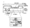
図4(A)には、発光装置、具体的にはELモジュールの断面を示す。また図4(B)には、ELモジュールの発光素子(有機化合物層、第1の導電膜及び第2の導電膜を有する)の積層構造を拡大したものを示す。 FIG. 4A shows a cross section of a light-emitting device, specifically, an EL module. FIG. 4B shows an enlarged view of a stacked structure of a light-emitting element (having an organic compound layer, a first conductive film, and a second conductive film) of an EL module.
図4(A)において、第1の基板400、下地絶縁膜401、本発明のレーザ照射装置を用いたレーザアニールにより形成される半導体膜を有するTFT422、第1の導電膜(電極)403、絶縁物(隔壁、土手、バンクとも呼ばれる)404、有機化合物層405、第2の導電膜(電極)406、保護膜407、空隙408、第2の基板409である。
In FIG. 4A, a first substrate 400, a base insulating film 401, a
第1の基板及び第2の基板としては、ガラス基板、石英基板やシリコン基板、プラスチック基板、金属基板、ステンレス基板、可撓性基板などを用いることができる。可撓性基板とは、PET、PES、PEN、アクリルなどからなるフィルム状の基板のことであり、可撓性基板を用いて半導体装置を作製すれば、軽量化が見込まれる。可撓性基板の表面、または表面および裏面にアルミ膜(AlON、AlN、AlOなど)、炭素膜(DLCなど)、SiNなどのバリア層を単層または多層にして形成すれば、耐久性やガスバリア性などが向上するので望ましい。 As the first substrate and the second substrate, a glass substrate, a quartz substrate, a silicon substrate, a plastic substrate, a metal substrate, a stainless steel substrate, a flexible substrate, or the like can be used. A flexible substrate is a film-like substrate made of PET, PES, PEN, acrylic, or the like. If a semiconductor device is manufactured using a flexible substrate, weight reduction is expected. If a barrier layer such as an aluminum film (AlON, AlN, AlO, etc.), a carbon film (DLC, etc.), SiN or the like is formed on the surface of the flexible substrate or on the front and back surfaces, the durability and gas barrier This is desirable because of improved properties.
なお有機化合物層からの発光が上方又は下方のいずれかに出射されるかにより、第1の導電膜及び第2の導電膜のいずれかを透光性をするITO等から形成する。また両方に出射する場合は、第1の導電膜及び第2の導電膜を、透光性を有する導電膜とすればよい。 Note that either the first conductive film or the second conductive film is formed of light-transmitting ITO or the like depending on whether light emitted from the organic compound layer is emitted upward or downward. In the case of emitting light to both, the first conductive film and the second conductive film may be light-transmitting conductive films.
第1の基板400上に設けられたTFT422(pチャネル型TFT)は、有機化合物層405に流れる電流を制御する素子であり、ドレイン領域(またはソース領域)として機能する不純物領域411と、チャネル形成領域412と、チャネル形成領域上に設けられたゲート電極417を有する。また、第1の導電膜403に接続され、ドレイン領域(またはソース領域)に接続されるドレイン電極(またはソース電極)416を有する。また、ドレイン電極416と同じ工程で電源供給線やソース配線などの配線418が同時に形成される。
A TFT 422 (p-channel TFT) provided over the first substrate 400 is an element that controls current flowing in the
第1の基材400上には下地絶縁膜(ここでは、下層を窒化絶縁膜、上層を酸化絶縁膜)となる下地絶縁401形成されており、ゲート電極417と半導体膜との間には、ゲート絶縁膜が設けられている。また、層間絶縁膜402は有機材料または無機材料を有するように形成される。ここでは図示しないが、一つの画素には、他にもTFT(nチャネル型TFTまたはpチャネル型TFT)を一つ、または複数設けている。また、一つのチャネル形成領域412を有するTFTを示したが、特に限定されず、複数のチャネルを有するTFTとしてもよい。
Over the first base material 400, a base insulating film 401 that is a base insulating film (here, a lower layer is a nitride insulating film and an upper layer is an oxide insulating film) is formed, and between the
また本実施の形態ではトップゲート型TFTを例として説明したが、TFT構造に関係なく本発明を適用することが可能であり、例えばボトムゲート型(逆スタガ型)TFTや順スタガ型TFTに適用することが可能である。 In this embodiment mode, the top gate TFT is described as an example. However, the present invention can be applied regardless of the TFT structure. For example, the present invention can be applied to a bottom gate type (reverse stagger type) TFT or a forward stagger type TFT. Is possible.
また、第1の導電膜403は、発光素子の陽極(或いは陰極)となる。第1の導電膜において、透明導電膜を用いる場合、ITO(酸化インジウム酸化スズ合金)、酸化インジウム酸化亜鉛合金(In2O3―ZnO)、酸化亜鉛(ZnO)等を用いることができる。 In addition, the first conductive film 403 serves as an anode (or a cathode) of the light emitting element. In the first conductive film, when using a transparent conductive film, ITO (indium tin oxide alloy), indium oxide-zinc oxide alloy (In 2 O 3 -ZnO), it can be used zinc oxide (ZnO) and the like.
また、第1の導電膜403の端部(および配線418)を覆う絶縁物404(バンク、隔壁、障壁、土手などと呼ばれる)を有している。絶縁物404としては、無機材料(酸化シリコン、窒化シリコン、酸化窒化シリコンなど)、感光性または非感光性の有機材料(ポリイミド、アクリル、ポリアミド、ポリイミドアミド、レジストまたはベンゾシクロブテン)、またはこれらの積層などを用いることができる。なお本実施の形態では、窒化シリコン膜で覆われた感光性の有機樹脂を用いる。例えば、有機樹脂の材料としてポジ型の感光性アクリルを用いた場合、絶縁物の上端部のみに曲率半径を有する曲面を持たせることが好ましい。また、絶縁物として、感光性の光によってエッチャントに不溶解性となるネガ型、或いは光によってエッチャントに溶解性となるポジ型のいずれも使用することができる。 In addition, an insulator 404 (referred to as a bank, a partition, a barrier, a bank, or the like) is provided to cover an end portion (and the wiring 418) of the first conductive film 403. As the insulator 404, an inorganic material (silicon oxide, silicon nitride, silicon oxynitride, or the like), a photosensitive or non-photosensitive organic material (polyimide, acrylic, polyamide, polyimide amide, resist, or benzocyclobutene), or a material thereof Lamination etc. can be used. Note that in this embodiment mode, a photosensitive organic resin covered with a silicon nitride film is used. For example, when positive photosensitive acrylic is used as the organic resin material, it is preferable that only the upper end portion of the insulator has a curved surface having a curvature radius. As the insulator, either a negative type that becomes insoluble in an etchant by photosensitive light or a positive type that becomes soluble in an etchant by light can be used.
また、有機化合物層405は、蒸着法または塗布法を用いて形成する。本実施の形態では、有機化合物層を蒸着装置で成膜を行い、均一な膜厚を得る。なお、信頼性を向上させるため、有機化合物層405の形成直前に真空加熱(100℃〜250℃)を行って脱気することが好ましい。例えば、蒸着法を用いる場合、真空度が5×10⁻³Torr(0.665Pa)以下、好ましくは10-4〜10-6Paまで真空排気された成膜室で蒸着を行う。蒸着の際、予め、加熱により有機化合物は気化されており、蒸着時にシャッターが開くことにより基板の方向へ飛散する。気化された有機化合物は、上方に飛散し、メタルマスクに設けられた開口部を通って蒸着される。
The
なお図4(B)に示すように、有機化合物層(EL層)405は、陽極側から順に、HIL(ホール注入層)、HTL(ホール輸送層)、EML(発光層)、ETL(電子輸送層)、EIL(電子注入層)の順に積層されている。代表的には、HILとしてCuPc、HTLとしてα−NPD、ETLとしてBCP、EILとしてBCP:Liをそれぞれ用いる。 As shown in FIG. 4B, the organic compound layer (EL layer) 405 includes, in order from the anode side, HIL (hole injection layer), HTL (hole transport layer), EML (light emitting layer), ETL (electron transport). Layer) and EIL (electron injection layer). Typically, CuPc is used as HIL, α-NPD is used as HTL, BCP is used as ETL, and BCP: Li is used as EIL.
また、有機化合物層(EL層)405として、フルカラー表示とする場合、赤色(R)、緑色(G)、青色(B)の発光を示す材料を、それぞれ蒸着マスクを用いた蒸着法、またはインクジェット法などによって適宜、選択的に形成すればよい。なおインクジェット法とは、導電膜や絶縁膜などの材料が混入された組成物の液滴(ドットとも表記する)を選択的に吐出(噴出)する方法である。具体的には、HILとしてCuPcやPEDOT、HTLとしてα−NPD、ETLとしてBCPやAlq3、EILとしてBCP:LiやCaF2をそれぞれ用いる。また例えばEMLは、R、G、Bのそれぞれの発光色に対応したドーパント(Rの場合DCM等、Gの場合DMQD等)をドープしたAlq3を用いればよい。なお、上記有機化合物層の積層構造に限定されない。 In addition, in the case of full-color display as the organic compound layer (EL layer) 405, a material that emits red (R), green (G), and blue (B) light is deposited by an evaporation method using an evaporation mask or an inkjet. What is necessary is just to selectively form suitably according to the method. Note that the inkjet method is a method in which droplets (also referred to as dots) of a composition mixed with a material such as a conductive film or an insulating film are selectively ejected (ejected). Specifically, CuPc or PEDOT is used as HIL, α-NPD is used as HTL, BCP or Alq 3 is used as ETL, and BCP: Li or CaF 2 is used as EIL. Further, for example, EML may be Alq 3 doped with a dopant corresponding to each emission color of R, G, and B (DCM in the case of R, DMQD in the case of G). In addition, it is not limited to the laminated structure of the said organic compound layer.
より具体的な有機化合物層の積層構造は、赤色の発光を示す有機化合物層405を形成する場合、例えば、CuPcを30nm形成し、α-NPDを60nm形成した後、同一のマスクを用いて、赤色の発光層としてDCM2及びルブレンが添加されたAlq3を40nm形成し、電子輸送層としてBCPを40nm形成し、電子注入層としてLiが添加されたBCPを1nm形成する。また、緑色の発光を示す有機化合物層を形成する場合、例えば、CuPcを30nm形成し、α―NPDを60nm成膜した後、同一の蒸着マスクを用いて、緑色の発光層としてクマリン545Tが添加されたAlq3を40nm形成し、電子輸送層としてBCPを40nm形成し、電子注入層としてLiが添加されたBCPを1nm形成する。また、青色の発光を示す有機化合物を含む層を形成する場合、例えば、CuPcを30nm形成し、α-NPDを60nm形成した後、同一のマスクを用いて発光層としてビス[2−(2−ヒドロキシフェニル)ベンゾオキサゾラト]亜鉛:Zn(PBO)2を10nm形成し、電子輸送層としてBCPを40nm成膜し、電子注入層としてLiが添加されたBCPを1nm形成する。
More specifically, in the case of forming the
以上、各色の有機化合物層のうち、共通しているCuPcやα-NPDは、画素部全面に形成することができる。またマスクは、各色で共有することもでき、例えば、赤色の有機化合物層を形成後、マスクをずらして、緑色の有機化合物層、再度マスクをずらして青色の有機化合物層を形成することができる。なお、形成する各色の有機化合物層の順序は適宜設定すればよい。 As described above, among the organic compound layers of the respective colors, common CuPc and α-NPD can be formed on the entire surface of the pixel portion. The mask can also be shared by each color. For example, after forming the red organic compound layer, the mask can be shifted to form the green organic compound layer, and the mask can be shifted again to form the blue organic compound layer. . In addition, what is necessary is just to set the order of the organic compound layer of each color to form suitably.
また白色発光の場合、カラーフィルターや色変換層などを別途設けることによってフルカラー表示を行ってもよい。上方に発光する白色光に対するカラーフィルターや色変換層は、第2の基板に設けた後、張り合わせればよい。また、下方に発光する白色光に対するカラーフィルターや色変換層は、ドレイン電極(またはソース電極)416を形成後、絶縁膜を介して形成することができる。その後、カラーフィルターや色変換層上に絶縁膜、第2の導電膜の順に形成し、ドレイン電極(またはソース電極)416と第2の導電膜とは、絶縁膜に形成されるコンタクトを介して接続すればよい。 In the case of white light emission, full color display may be performed by separately providing a color filter, a color conversion layer, or the like. A color filter and a color conversion layer for white light emitted upward may be provided after being provided over the second substrate. Further, a color filter and a color conversion layer for white light emitted downward can be formed through an insulating film after the drain electrode (or source electrode) 416 is formed. After that, an insulating film and a second conductive film are formed in this order on the color filter and the color conversion layer, and the drain electrode (or source electrode) 416 and the second conductive film are connected via a contact formed in the insulating film. Just connect.
本発明のレーザ照射装置、及びレーザ照射方法により、均一性の高い結晶性半導体膜を有する発光装置を提供することができる。その結果、表示部において、表示ムラに起因するレーザビームのムラの低減された発光装置を提供することができる。 With the laser irradiation apparatus and the laser irradiation method of the present invention, a light-emitting device having a highly uniform crystalline semiconductor film can be provided. As a result, a light-emitting device in which unevenness of a laser beam due to display unevenness is reduced in the display portion can be provided.
なお、本発明のアクティブマトリクス基板は液晶表示装置やその他の表示装置、更には半導体集積回路やCPUにも採用することができる。 Note that the active matrix substrate of the present invention can also be used in liquid crystal display devices and other display devices, and also in semiconductor integrated circuits and CPUs.
(実施の形態5)
本発明により作製されたアクティブマトリクス基板は、様々な電子機器に適用することができる。電子機器としては、携帯情報端末(携帯電話機、モバイルコンピュータ、携帯型ゲーム機又は電子書籍等)、ビデオカメラ、デジタルカメラ、ゴーグル型ディスプレイ、表示ディスプレイ、ナビゲーションシステム等が挙げられる。これら電子機器の具体例を図5に示す。
(Embodiment 5)
The active matrix substrate manufactured according to the present invention can be applied to various electronic devices. Examples of the electronic device include a portable information terminal (a mobile phone, a mobile computer, a portable game machine, an electronic book, etc.), a video camera, a digital camera, a goggle type display, a display display, a navigation system, and the like. Specific examples of these electronic devices are shown in FIGS.
図5(A)はディスプレイであり、筐体4001、音声出力部4002、表示部4003等を含む。本発明により形成されたアクティブマトリクス基板により発光素子又は液晶材料を有する表示部4003を完成することができる。表示装置は、パソコン用、TV放送受信用、広告表示用など全ての情報表示装置が含まれる。
FIG. 5A illustrates a display, which includes a
図5(B)はモバイルコンピュータであり、本体4101、スタイラス4102、表示部4103、操作ボタン4104、外部インターフェイス4105等を含む。本発明により形成されたアクティブマトリクス基板により発光素子や液晶材料を有する表示部4103を完成することができる。
FIG. 5B illustrates a mobile computer, which includes a
図5(C)はゲーム機であり、本体4201、表示部4202、操作ボタン4203等を含む。本発明により形成されたアクティブマトリクス基板により発光素子や液晶材料を有する表示部4202を完成することができる。図5(D)は携帯電話機であり、本体4301、音声出力部4302、音声入力部4303、表示部4304、操作スイッチ4305、アンテナ4306等を含む。本発明により形成されたアクティブマトリクス基板により発光素子や液晶材料を有する表示部4304を完成することができる。
FIG. 5C illustrates a game machine, which includes a
図5(E)は電子ブックリーダーであり、表示部4401等を含む。本発明により形成されたアクティブマトリクス基板により発光素子や液晶材料を有する表示部4202を完成することができる。
FIG. 5E illustrates an electronic book reader, which includes a
以上のように、本発明の適用範囲は極めて広く、あらゆる分野の電子機器に用いることが可能である。特に、アクティブマトリクス基板の絶縁基板をフレキシブル基板とすることで薄型化や軽量化が実現することができる。 As described above, the applicable range of the present invention is so wide that the present invention can be used for electronic devices in various fields. In particular, it is possible to reduce the thickness and weight by using a flexible substrate as the insulating substrate of the active matrix substrate.
(実施の形態6)
なお本発明はCWビームに限定されず、パルス的に出力されるエネルギービーム(パルスビーム、特に、光源にレーザを使用する場合パルスレーザと表記する。)であっても、半導体膜がレーザ光によって溶融してから固化するまでに、次のレーザ光を照射できるような発振周波数でレーザ光を発振させることで、走査方向に向かって連続的に成長した結晶粒を得ることができれば、本発明の効果を奏することができる。すなわち、パルス発振の周期(発振周波数)が、半導体膜が溶融してから完全に固化するまでの時間よりも短くなるように、発振周波数の下限を定めたパルスビームを使用してもよい。例えば光源にレーザを用いたパルスレーザにおいて、具体的な発振周波数は10MHz以上とし、通常用いられている数十Hz〜数百Hzの周波数よりも著しく高い周波数を使用する。
(Embodiment 6)
Note that the present invention is not limited to the CW beam, and the semiconductor film is formed by a laser beam even if it is an energy beam that is output in a pulsed manner (a pulse beam, particularly a pulse laser when a laser is used as a light source). If crystal grains continuously grown in the scanning direction can be obtained by oscillating laser light at an oscillation frequency that can be irradiated with the next laser light from melting to solidification, There is an effect. That is, a pulse beam in which the lower limit of the oscillation frequency is determined so that the period of pulse oscillation (oscillation frequency) is shorter than the time from when the semiconductor film is melted until it is completely solidified. For example, in a pulse laser using a laser as a light source, a specific oscillation frequency is set to 10 MHz or more, and a frequency significantly higher than a frequency of several tens to several hundreds Hz that is usually used is used.
高い周波数を使用する理由を説明すると、パルスレーザでは、レーザ光を半導体膜に照射してから半導体膜が完全に固化するまでの時間は数十nsec〜数百nsecと言われており、上記周波数を用いることで、半導体膜がレーザ光によって溶融してから固化するまでに、次のレーザ光を照射することができる。したがって、従来のパルスレーザを用いる場合と異なり、半導体膜中において固液界面を連続的に移動させることができるので、走査方向に向かって連続的に成長した結晶粒を有する半導体膜が形成される。具体的には、結晶粒の走査方向における幅が10〜30μm、走査方向に対して垂直な方向における幅が1〜5μm程度の結晶粒の集合を形成することができ、CWレーザと同程度の結晶粒を得ることができる。そして該走査方向に沿って長く伸びた単結晶の結晶粒を形成することで、少なくともTFTのキャリアの移動方向には結晶粒界のほとんど存在しない半導体膜の形成が可能となる。 The reason why a high frequency is used will be explained. In a pulse laser, it is said that the time from when a semiconductor film is irradiated with laser light until the semiconductor film is completely solidified is several tens to several hundreds of nsec. By using, the next laser beam can be irradiated from when the semiconductor film is melted by the laser beam to solidification. Therefore, unlike the case of using a conventional pulse laser, the solid-liquid interface can be continuously moved in the semiconductor film, so that a semiconductor film having crystal grains continuously grown in the scanning direction is formed. . Specifically, a set of crystal grains having a width of 10 to 30 μm in the scanning direction of crystal grains and a width of about 1 to 5 μm in a direction perpendicular to the scanning direction can be formed. Crystal grains can be obtained. By forming single crystal crystal grains extending long along the scanning direction, it is possible to form a semiconductor film having almost no crystal grain boundaries in at least the TFT carrier movement direction.
上記周波数での発振が可能であるならば、パルスビームとしてArレーザ、Krレーザ、エキシマレーザ、CO2レーザ、YAGレーザ、Y2O3レーザ、YVO4レーザ、YLFレーザ、YAlO3レーザ、ガラスレーザ、ルビーレーザ、アレキサンドライトレーザ、Ti:サファイヤレーザ、銅蒸気レーザまたは金蒸気レーザから射出されるビームを用いることができる。 If oscillation at the above-mentioned frequency is possible, Ar laser, Kr laser, excimer laser, CO 2 laser, YAG laser, Y 2 O 3 laser, YVO 4 laser, YLF laser, YAlO 3 laser, glass laser can be used as the pulse beam. A beam emitted from a ruby laser, an alexandrite laser, a Ti: sapphire laser, a copper vapor laser, or a gold vapor laser can be used.
例えば、レーザ光として、エネルギー2W、TEM(00)の発振モード、第2高調波(532nm)、発振周波数80MHz、パルス幅12psecのYVO4レーザ光を用いることができ、この発振器を有するパルスレーザ照射装置を用いることができる。なお、レーザ光を光学系により加工することで半導体膜の表面に形成されるスポットは、短軸10μm、長軸100μmの矩形状とすることができる。発振周波数を80MHzとすることで、固液界面を連続的に移動させることができるので、走査方向に向かって連続的に成長した結晶粒が形成される。該走査方向に沿って長く延びた単結晶の粒を形成することで、少なくともTFTのキャリアの移動方向、つまりチャネル方向には結晶粒界のほとんど存在しない半導体膜の形成が可能となる。 For example, YVO 4 laser light having energy 2 W, TEM (00) oscillation mode, second harmonic (532 nm), oscillation frequency 80 MHz, pulse width 12 psec can be used as laser light, and pulse laser irradiation with this oscillator is performed. An apparatus can be used. Note that spots formed on the surface of the semiconductor film by processing laser light with an optical system can have a rectangular shape with a short axis of 10 μm and a long axis of 100 μm. Since the solid-liquid interface can be continuously moved by setting the oscillation frequency to 80 MHz, crystal grains that are continuously grown in the scanning direction are formed. By forming single crystal grains extending in the scanning direction, it is possible to form a semiconductor film having almost no crystal grain boundaries in at least the TFT carrier movement direction, that is, the channel direction.
すなわち本発明は、連続的又はパルス的に発振されるビームのいずれを用いて走査する場合であっても、レーザ光のスポットの走査速度が所定値以外となるとき、遮光することを特徴とする。 That is, the present invention is characterized in that light is shielded when the scanning speed of the laser light spot is other than a predetermined value, regardless of whether scanning is performed using a beam oscillated continuously or in pulses. .
Claims (10)
前記走査する手段よりも下流にある、前記ビームを前記被照射物上で焦点を結ぶためのf−θレンズと、
前記ビームの走査開始位置及び走査終了位置で前記ビームを遮光する手段と、
を有し、
前記走査する手段はガルバノミラー又はポリゴンミラーであり、
前記遮光する手段と前記被照射物との距離は1cm以下であることを特徴とするビーム照射装置。 Means for scanning an energy beam of a harmonic of a laser output with a pulse of 10 MHz or more on an object to be irradiated;
An f-θ lens for focusing the beam on the irradiated object downstream of the scanning means;
It means for shielding the front Symbol beam at the scanning start position and the scanning end position of said beam,
Have
The means for scanning is a galvanometer mirror or a polygon mirror,
The beam irradiation apparatus characterized in that a distance between the light shielding means and the irradiation object is 1 cm or less.
前記走査する手段よりも下流にあるf−θレンズと、
前記ビームの走査開始位置及び走査終了位置で前記ビームを遮光する手段と、により半導体膜上で焦点を結びながら走査する半導体装置の作製方法であって、
前記走査する手段はガルバノミラー又はポリゴンミラーであり、
前記遮光する手段と前記半導体膜との距離を1cm以下とすることを特徴とする半導体装置の作製方法。 Means for scanning an energy beam of a harmonic of a laser output with a pulse of 10 MHz or more;
An f-θ lens downstream of the scanning means;
A method for manufacturing a semiconductor device for scanning with tie means for blocking, by focusing on the semiconductor film before Symbol beam at the scanning start position and the scanning end position of said beam,
The means for scanning is a galvanometer mirror or a polygon mirror,
A method for manufacturing a semiconductor device, wherein a distance between the light shielding means and the semiconductor film is 1 cm or less.
Priority Applications (1)
| Application Number | Priority Date | Filing Date | Title |
|---|---|---|---|
| JP2004123452A JP4503344B2 (en) | 2003-04-21 | 2004-04-19 | Beam irradiation apparatus and method for manufacturing semiconductor device |
Applications Claiming Priority (2)
| Application Number | Priority Date | Filing Date | Title |
|---|---|---|---|
| JP2003116392 | 2003-04-21 | ||
| JP2004123452A JP4503344B2 (en) | 2003-04-21 | 2004-04-19 | Beam irradiation apparatus and method for manufacturing semiconductor device |
Publications (3)
| Publication Number | Publication Date |
|---|---|
| JP2004343093A JP2004343093A (en) | 2004-12-02 |
| JP2004343093A5 JP2004343093A5 (en) | 2007-05-24 |
| JP4503344B2 true JP4503344B2 (en) | 2010-07-14 |
Family
ID=33543088
Family Applications (1)
| Application Number | Title | Priority Date | Filing Date |
|---|---|---|---|
| JP2004123452A Expired - Fee Related JP4503344B2 (en) | 2003-04-21 | 2004-04-19 | Beam irradiation apparatus and method for manufacturing semiconductor device |
Country Status (1)
| Country | Link |
|---|---|
| JP (1) | JP4503344B2 (en) |
Families Citing this family (6)
| Publication number | Priority date | Publication date | Assignee | Title |
|---|---|---|---|---|
| EP1547719A3 (en) * | 2003-12-26 | 2009-01-28 | Semiconductor Energy Laboratory Co., Ltd. | Laser irradiation apparatus, laser irradiation method, and method for manufacturing crystalline semiconductor film |
| JP4999323B2 (en) * | 2004-12-03 | 2012-08-15 | 株式会社半導体エネルギー研究所 | Method for manufacturing semiconductor device |
| EP1716964B1 (en) | 2005-04-28 | 2009-01-21 | Semiconductor Energy Laboratory Co., Ltd. | Method for manufacturing semiconductor device and laser irradiation apparatus |
| JP5089077B2 (en) * | 2005-04-28 | 2012-12-05 | 株式会社半導体エネルギー研究所 | Method for manufacturing semiconductor device |
| CN101331592B (en) | 2005-12-16 | 2010-06-16 | 株式会社半导体能源研究所 | Laser irradiation apparatus, laser irradiation method and manufacturing method of semiconductor device |
| JP5137388B2 (en) * | 2005-12-16 | 2013-02-06 | 株式会社半導体エネルギー研究所 | Laser irradiation apparatus, laser irradiation method, and manufacturing method of semiconductor device |
Citations (3)
| Publication number | Priority date | Publication date | Assignee | Title |
|---|---|---|---|---|
| JP2003045820A (en) * | 2001-07-30 | 2003-02-14 | Semiconductor Energy Lab Co Ltd | Laser irradiation apparatus, and method, and method of manufacturing semiconductor device |
| JP2003059859A (en) * | 2001-08-10 | 2003-02-28 | Semiconductor Energy Lab Co Ltd | Device and method for irradiating laser and method for manufacturing semiconductor device |
| JP2004056058A (en) * | 2002-07-24 | 2004-02-19 | Hitachi Ltd | Manufacturing method for image display unit |
Family Cites Families (1)
| Publication number | Priority date | Publication date | Assignee | Title |
|---|---|---|---|---|
| JPH01276621A (en) * | 1988-04-27 | 1989-11-07 | Mitsubishi Electric Corp | Beam annealing apparatus |
-
2004
- 2004-04-19 JP JP2004123452A patent/JP4503344B2/en not_active Expired - Fee Related
Patent Citations (3)
| Publication number | Priority date | Publication date | Assignee | Title |
|---|---|---|---|---|
| JP2003045820A (en) * | 2001-07-30 | 2003-02-14 | Semiconductor Energy Lab Co Ltd | Laser irradiation apparatus, and method, and method of manufacturing semiconductor device |
| JP2003059859A (en) * | 2001-08-10 | 2003-02-28 | Semiconductor Energy Lab Co Ltd | Device and method for irradiating laser and method for manufacturing semiconductor device |
| JP2004056058A (en) * | 2002-07-24 | 2004-02-19 | Hitachi Ltd | Manufacturing method for image display unit |
Also Published As
| Publication number | Publication date |
|---|---|
| JP2004343093A (en) | 2004-12-02 |
Similar Documents
| Publication | Publication Date | Title |
|---|---|---|
| US7915099B2 (en) | Beam irradiation apparatus, beam irradiation method, and method for manufacturing semiconductor device | |
| US7746528B2 (en) | Beam irradiation apparatus, beam irradiation method, and method for manufacturing thin film transistor | |
| US7476629B2 (en) | Beam irradiation apparatus, beam irradiation method, and method for manufacturing thin film transistor | |
| US7247527B2 (en) | Method for manufacturing semiconductor device, and laser irradiation apparatus | |
| JP5227900B2 (en) | Method for manufacturing semiconductor device | |
| JP4127565B2 (en) | Method for manufacturing semiconductor device | |
| US7217605B2 (en) | Laser irradiation method and method of manufacturing a semiconductor device | |
| TWI423299B (en) | Laser irradiation apparatus and method for manufacturing semiconductor device | |
| JP3949564B2 (en) | Laser irradiation apparatus and method for manufacturing semiconductor device | |
| TWI291729B (en) | A semiconductor fabricating apparatus | |
| JP2003209065A (en) | Semiconductor device, method of manufacturing the same, semiconductor device manufacturing system, and electronic device | |
| JP2010028128A (en) | Method of fablicating emiconductor device | |
| JP2003045820A (en) | Laser irradiation apparatus, and method, and method of manufacturing semiconductor device | |
| US8269136B2 (en) | Laser beam treatment device and semiconductor device | |
| US20040266147A1 (en) | Method for manufacturing a thin film transistor and method for manufacturing a semiconductor device | |
| JP4503344B2 (en) | Beam irradiation apparatus and method for manufacturing semiconductor device | |
| JP4515136B2 (en) | Laser beam irradiation apparatus and method for manufacturing thin film transistor | |
| JP4503343B2 (en) | Beam irradiation apparatus, beam irradiation method, and method for manufacturing thin film transistor | |
| JP2003151916A (en) | Laser irradiation apparatus and method and manufacturing method of semiconductor device | |
| JP2004072086A (en) | Method for laser irradiation and laser irradiator | |
| JP2003158076A (en) | Semiconductor device, manufacturing method therefor and electronic apparatus | |
| JP2007103957A (en) | Laser irradiation apparatus | |
| JP2005039249A (en) | Method of manufacturing thin film transistor and semiconductor device |
Legal Events
| Date | Code | Title | Description |
|---|---|---|---|
| A521 | Written amendment |
Free format text: JAPANESE INTERMEDIATE CODE: A523 Effective date: 20070330 |
|
| A621 | Written request for application examination |
Free format text: JAPANESE INTERMEDIATE CODE: A621 Effective date: 20070330 |
|
| A977 | Report on retrieval |
Free format text: JAPANESE INTERMEDIATE CODE: A971007 Effective date: 20081209 |
|
| A131 | Notification of reasons for refusal |
Free format text: JAPANESE INTERMEDIATE CODE: A131 Effective date: 20091201 |
|
| A521 | Written amendment |
Free format text: JAPANESE INTERMEDIATE CODE: A523 Effective date: 20100119 |
|
| A131 | Notification of reasons for refusal |
Free format text: JAPANESE INTERMEDIATE CODE: A131 Effective date: 20100216 |
|
| A521 | Written amendment |
Free format text: JAPANESE INTERMEDIATE CODE: A523 Effective date: 20100402 |
|
| TRDD | Decision of grant or rejection written | ||
| A01 | Written decision to grant a patent or to grant a registration (utility model) |
Free format text: JAPANESE INTERMEDIATE CODE: A01 Effective date: 20100420 |
|
| A01 | Written decision to grant a patent or to grant a registration (utility model) |
Free format text: JAPANESE INTERMEDIATE CODE: A01 |
|
| A61 | First payment of annual fees (during grant procedure) |
Free format text: JAPANESE INTERMEDIATE CODE: A61 Effective date: 20100421 |
|
| R150 | Certificate of patent or registration of utility model |
Free format text: JAPANESE INTERMEDIATE CODE: R150 |
|
| FPAY | Renewal fee payment (event date is renewal date of database) |
Free format text: PAYMENT UNTIL: 20130430 Year of fee payment: 3 |
|
| FPAY | Renewal fee payment (event date is renewal date of database) |
Free format text: PAYMENT UNTIL: 20130430 Year of fee payment: 3 |
|
| FPAY | Renewal fee payment (event date is renewal date of database) |
Free format text: PAYMENT UNTIL: 20130430 Year of fee payment: 3 |
|
| FPAY | Renewal fee payment (event date is renewal date of database) |
Free format text: PAYMENT UNTIL: 20140430 Year of fee payment: 4 |
|
| R250 | Receipt of annual fees |
Free format text: JAPANESE INTERMEDIATE CODE: R250 |
|
| R250 | Receipt of annual fees |
Free format text: JAPANESE INTERMEDIATE CODE: R250 |
|
| R250 | Receipt of annual fees |
Free format text: JAPANESE INTERMEDIATE CODE: R250 |
|
| R250 | Receipt of annual fees |
Free format text: JAPANESE INTERMEDIATE CODE: R250 |
|
| LAPS | Cancellation because of no payment of annual fees |