JP4502240B2 - Rotating machine with seal assembly - Google Patents
Rotating machine with seal assembly Download PDFInfo
- Publication number
- JP4502240B2 JP4502240B2 JP2000393950A JP2000393950A JP4502240B2 JP 4502240 B2 JP4502240 B2 JP 4502240B2 JP 2000393950 A JP2000393950 A JP 2000393950A JP 2000393950 A JP2000393950 A JP 2000393950A JP 4502240 B2 JP4502240 B2 JP 4502240B2
- Authority
- JP
- Japan
- Prior art keywords
- blade
- tip
- rotor
- casing
- flexible body
- Prior art date
- Legal status (The legal status is an assumption and is not a legal conclusion. Google has not performed a legal analysis and makes no representation as to the accuracy of the status listed.)
- Expired - Fee Related
Links
Images


Classifications
-
- F—MECHANICAL ENGINEERING; LIGHTING; HEATING; WEAPONS; BLASTING
- F01—MACHINES OR ENGINES IN GENERAL; ENGINE PLANTS IN GENERAL; STEAM ENGINES
- F01D—NON-POSITIVE DISPLACEMENT MACHINES OR ENGINES, e.g. STEAM TURBINES
- F01D11/00—Preventing or minimising internal leakage of working-fluid, e.g. between stages
- F01D11/08—Preventing or minimising internal leakage of working-fluid, e.g. between stages for sealing space between rotor blade tips and stator
- F01D11/12—Preventing or minimising internal leakage of working-fluid, e.g. between stages for sealing space between rotor blade tips and stator using a rubstrip, e.g. erodible. deformable or resiliently-biased part
- F01D11/122—Preventing or minimising internal leakage of working-fluid, e.g. between stages for sealing space between rotor blade tips and stator using a rubstrip, e.g. erodible. deformable or resiliently-biased part with erodable or abradable material
-
- F—MECHANICAL ENGINEERING; LIGHTING; HEATING; WEAPONS; BLASTING
- F05—INDEXING SCHEMES RELATING TO ENGINES OR PUMPS IN VARIOUS SUBCLASSES OF CLASSES F01-F04
- F05D—INDEXING SCHEME FOR ASPECTS RELATING TO NON-POSITIVE-DISPLACEMENT MACHINES OR ENGINES, GAS-TURBINES OR JET-PROPULSION PLANTS
- F05D2300/00—Materials; Properties thereof
- F05D2300/10—Metals, alloys or intermetallic compounds
-
- F—MECHANICAL ENGINEERING; LIGHTING; HEATING; WEAPONS; BLASTING
- F05—INDEXING SCHEMES RELATING TO ENGINES OR PUMPS IN VARIOUS SUBCLASSES OF CLASSES F01-F04
- F05D—INDEXING SCHEME FOR ASPECTS RELATING TO NON-POSITIVE-DISPLACEMENT MACHINES OR ENGINES, GAS-TURBINES OR JET-PROPULSION PLANTS
- F05D2300/00—Materials; Properties thereof
- F05D2300/20—Oxide or non-oxide ceramics
- F05D2300/21—Oxide ceramics
-
- F—MECHANICAL ENGINEERING; LIGHTING; HEATING; WEAPONS; BLASTING
- F05—INDEXING SCHEMES RELATING TO ENGINES OR PUMPS IN VARIOUS SUBCLASSES OF CLASSES F01-F04
- F05D—INDEXING SCHEME FOR ASPECTS RELATING TO NON-POSITIVE-DISPLACEMENT MACHINES OR ENGINES, GAS-TURBINES OR JET-PROPULSION PLANTS
- F05D2300/00—Materials; Properties thereof
- F05D2300/50—Intrinsic material properties or characteristics
- F05D2300/501—Elasticity
-
- F—MECHANICAL ENGINEERING; LIGHTING; HEATING; WEAPONS; BLASTING
- F05—INDEXING SCHEMES RELATING TO ENGINES OR PUMPS IN VARIOUS SUBCLASSES OF CLASSES F01-F04
- F05D—INDEXING SCHEME FOR ASPECTS RELATING TO NON-POSITIVE-DISPLACEMENT MACHINES OR ENGINES, GAS-TURBINES OR JET-PROPULSION PLANTS
- F05D2300/00—Materials; Properties thereof
- F05D2300/60—Properties or characteristics given to material by treatment or manufacturing
- F05D2300/601—Fabrics
- F05D2300/6012—Woven fabrics
-
- Y—GENERAL TAGGING OF NEW TECHNOLOGICAL DEVELOPMENTS; GENERAL TAGGING OF CROSS-SECTIONAL TECHNOLOGIES SPANNING OVER SEVERAL SECTIONS OF THE IPC; TECHNICAL SUBJECTS COVERED BY FORMER USPC CROSS-REFERENCE ART COLLECTIONS [XRACs] AND DIGESTS
- Y02—TECHNOLOGIES OR APPLICATIONS FOR MITIGATION OR ADAPTATION AGAINST CLIMATE CHANGE
- Y02T—CLIMATE CHANGE MITIGATION TECHNOLOGIES RELATED TO TRANSPORTATION
- Y02T50/00—Aeronautics or air transport
- Y02T50/60—Efficient propulsion technologies, e.g. for aircraft
Landscapes
- Engineering & Computer Science (AREA)
- Mechanical Engineering (AREA)
- General Engineering & Computer Science (AREA)
- Turbine Rotor Nozzle Sealing (AREA)
- Structures Of Non-Positive Displacement Pumps (AREA)
Description
【0001】
【発明の属する技術分野】
本発明は、一般に、蒸気やガスタービンのような回転機械に関し、より詳しくは、回転する動翼の先端と回転機械の固定外部ケーシングとの間のクリアランスを制御するシールアセンブリを持つ回転機械に関する。
【0002】
【従来の技術】
蒸気及びガスタービンは、いろいろ目的がある中で、電気発電機に動力を与えるために使用され、ガスタービンはまた、いろいろ目的がある中で、航空機や船舶を推進させるために使用される。蒸気タービンは、連続する流れの順に、蒸気入口、タービン及び蒸気出口を一般に含む蒸気経路を持つ。ガスタービンは、連続する流れの順に、空気入口(又は取入口)、圧縮器、燃焼室、タービン、ガス出口(又は排気ノズル)を一般に含むガス経路を持つ。圧縮器及びタービン部は、円周方向に少なくとも1つの回転翼の列を含む。回転翼の自由端又は先端は、固定子ケ−シングに囲まれている。
【0003】
タービンの効率は、動翼先端と周囲のケーシングとの間の半径方向のクリアランス又は隙間に部分的に左右される。クリアランスが大き過ぎる場合、より多くの蒸気又はガス流が動翼先端と周囲ケーシングとの間の隙間を通って漏れ、タービンの効率を減少させるであろう。クリアランスが小さ過ぎる場合、動翼の先端部は、特定のタービン作動状態の間、周囲ケーシングに衝突する可能性がある。
【0004】
クリアランスは、加速又は減速の間、翼の先端での遠心力が変わるため、また、回転するロータと固定ケーシングとの間の相対的な温度上昇のために変化するが知られている。ロータ及びケーシングの異なる遠心力及び温度上昇の間、クリアランスの変化は、動いている翼先端の固定ケーシングに対する激しい摩擦をもたらすことになり得る。翼先端クリアランスのこの増加は、効率損失をもたらす。
【0005】
【発明が解決しようとする課題】
硬質摩耗性シュラウドのようなクリアランス制御装置は、過去においてロータ及びケーシング間のクリアランス変化に適応させるために提案されてきた。しかし、そのようなクリアランスを制御する最適設計を表すものは全くないと思われる。以上の結果、上記のクリアランス制御の問題の解決策を、代わりに新しい問題を何も引き起こすことなく提供するであろう発明に対する必要性が依然残されている。
【0006】
【課題を解決するための手段】
本発明は、前述の必要性を満たすよう設計された可撓性摩耗シールアセンブリを備えた回転機械を提供する。可撓性摩耗シールアセンブリは、ケーシングに対するロータと翼との異なる膨張のために翼先端がケーシングに接触するのに応答し、曲がったり摩耗したりして回転機械の回転動翼と固定外部ケーシングとの間の半径方向クリアランス制御し、それにより、翼で摩耗層を動かすことで接触の激しさを減少させる。通常使用される硬質摩耗性シュラウドと比べると、本発明のシールアセンブリは、弾力性があるため、発熱や材料除去がより少なくなる。シールアセンブリの低減磨耗率は、より長期間に亘ってより狭い翼先端クリアランスを準備し、より良い稼働効率をもたらす。
【0007】
本発明の実施形態において、縦軸線の周りに回転可能で外面を持つロータと、装着され、円周方向に互いに間隔を空けて配置され、ロータの外面から翼の先端部に縦軸線に対して半径方向外側に延びる複数の翼と、環状形と内部円周面とを持ち、外部ケーシングの内部円周面と翼の先端部との間に環状隙間を形成するために、ロータ及び翼から半径方向外側に間隔を空けて周囲に固定的に配置されている外部ケーシングと、ケーシングに対してロータと翼とが異なる膨張をしている間、ロータと共に動く翼の先端がシールアセンブリに接触するのに応答してシールアセンブリが曲がり及び摩耗して、それにより、環状隙間でのケーシング及び動翼間のクリアランスが、動く翼先端がケーシングと接触するのを避けるような方法で制御されるように、外部ケーシングの内部円周面に取り付けられてケーシングと翼先端との間の環状クリアランス隙間内に配置された可撓性摩耗シールアセンブリと、を含む回転機械が提供される。
【0008】
可撓性摩耗シールアセンブリの異なる各実施形態が開示される。実施形態の各々において、シールアセンブリは、基本的に、外部ケーシングの内部円周面の環状形とほぼ適合する弓形を持つ細長い可撓体と、動翼の先端部の各々上流及び下流側に間隔を空けて置かれた対向する1対の縦方向に延びる間隔の空いた縁部分と、対向する各縁部分の間に延びてそれらを相互接続し、動翼の先端部と位置合わせされてその外側に向かって配置されている本体とを含む。細長い可撓体は、動翼の先端部の接触に応答して摩耗することが可能な材料である、動翼の先端部近傍に配置された部分を持つ。図において、可撓体は、互いに対して端から端まで配置された複数の似たような弓形体セグメントの環状アレーから作られている。
【0009】
各々の実施形態において、シールアセンブリは、更に基本的に、可撓体をその対向する各縁部分において外部ケーシングの内部円周面に固定する手段を含む。例として、該固定手段は、溶接又は留め具であり得る。
【0010】
【発明の実施の形態】
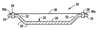
本発明は、回転機械である。回転機械は、非限定的に、遠心圧縮機、発電機及びタービンを含む。タービンは、非限定的に、蒸気タービン及びガスタービンを含む。タービンは、非限定的に、圧縮部及びタービン部を含む。本発明は、以下にタービンに関して説明されるが、当業者により理解される通り、本発明はそれに限定されず、いかなる回転機械にも適用されるものとする。図1は、回転機械の一部のみを示しており、その一部は、他にも部材がある中で、タービンのハウジング及びロータを含むことに注意されたい。
【0011】
ここで、添付図特に図1を参照すると、中央の縦軸線Aの周りに回転可能で外部環状表面12aを持つロータと、固定するように装着され、円周方向に互いに間隔を空けて配置され、ロータ12の外部環状表面12aから翼の先端部14aに半径方向外側に延びる複数の翼14と、ほぼ環及び円筒形状と内部円周面16aとを持ち、外部ケーシングの内部円周面16aと動翼14の先端部14aとの間に環状隙間18を形成するために、ロータ12及び翼14から半径方向外側に間隔を空けて周囲に固定的に配置されている外部ケーシング16とを持つ、本発明の一般に番号10で表されるタービンが概略的な形で図解されている。可撓性摩耗シールアセンブリ20は、外部ケーシング16の内部円周16aに取り付けられ、ケーシング16の内部円周16aとロータ12と共に回転する翼14の先端部14aとの間に形成された環状隙間18内に配置される。ケーシング16に対してロータ12と翼14とが異なる膨張をしている間、シールアセンブリ18は、動く翼の先端14aがシールアセンブリに接触するのに応答して曲がり及び摩耗する。このようにして、動く翼先端14aの固定ケーシング16との接触が避けられ、固定ケーシング16及び動く動翼14の間のクリアランスは、その結果、本発明のシールアセンブリ18により制御される。
【0012】
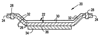
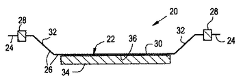
可撓性摩耗シールアセンブリ20は、図2から図11までに示されるように、異なる修正形状又は実施形態で準備することができる。各々の修正形状又は実施形態において、シールアセンブリ20は、基本的に、外部ケーシング16の内部円周面16aの環状形にほぼ適合する弓形を持つ細長い可撓体22を含む。可撓体22はまた、動翼14の先端部14aの各々上流及び下流側に間隔を空けて置かれた対向する1対の縦方向に延びる間隔の空いた縁部分24と、対向する各縁部分24の間に延びてそれらを相互接続し、動翼14の先端部14aと位置合わせされてその外側に向かって配置されている本体部分26とを持つ。図2から図11の各々の実施形態の細長い可撓体22は、動翼14の先端部14aの接触に応答して摩耗することが可能な材料である、動翼14の先端部14a近傍に配置された少なくとも一部分を持つ。図1において見ることができるように、可撓体22は、互いに対して端から端まで配置された複数の似たような弓形体セグメント22aの環状アレーから作られている。
【0013】
各々の実施形態において、シールアセンブリ20は、更に、可撓体22をその対向する各縁部分24において外部ケーシング14の内部円周面16aに固定する手段28を基本的に含む。例として、そして非限定的に、固定手段28は、複数のスポット溶接又は留め具であり得る。更に、固定手段は、可撓体22の対向する縁部分24を収容する、ケーシング16の溝を含むことができる。シールアセンブリ20は、その空気力学的抵抗を減らすために、ケーシング16内に隠すように定着させることができる。
【0014】
更に詳しくは、シールアセンブリ20の各実施形態の可撓体22の本体部分26は、動翼14の先端部14aの上に重なる中央部30と、可撓体22の対向する縁部分24と可撓体の本体部分26の中央部30とを相互接続する手段とを持っており、そのため、中央部30が外部ケーシング16の内部円周面16aから内部に向かって十分間隔があり、動翼14の動いている先端部14aによる接触に応答して本体部分が動翼14から遠ざかる方向そして外部ケーシング16に向かうような方向に曲がることを可能にする。可撓体22の本体部分26の中央部30は、曲がっていない状態においては、ほぼ平坦である。可撓体22の対向する各縁部分24と本体部分26の中央部30とを相互接続する手段は、可撓体22の対向する縁部分24と本体部分26の中央部30の対向する縁部30aとの間に配置され、それらに各々取り付けられた1対の対向する側部32である。可撓体22の本体部分26の対向する側部32は、本体部分26の中央部30を外部ケーシング16から内側に向かって目標とする間隔が空いた位置に配置するため、本体部分26の中央部30から相対して傾く関係で延びている。
【0015】
図2に見られるように、可撓体22そのものは、摩耗可能材料から作ることができる。例えば、摩耗可能材料は、セラミック又は適切な金属であり得る。更に、例示的であるが、可撓体22は、織布やシートの形でも可能である。加えて、可撓体22は、図2から図4、図10及び図11に見られるように、材料の1つの層であり得るが、また、図5から図9に見られるように、材料の複数の層でも可能である。可撓体22が複数の層である場合、それらは、剛性や漏れを減らすために、薄切りや千鳥にすることもできる。
【0016】
更に、摩耗材料が可撓体部22の摩耗材料から分離するところは、図3及び図7から図11に見られるように、可撓体22の本体部分26の中央部30の、動翼14の先端部14aに面している内面36に塗布された被覆層34の形をとる。可撓体22に装着される摩耗被膜34の使用はまた、浸食寿命の問題も解決する。被膜34の硬さとシールの剛性とを独立して変えられることは、シール剛性の減少を通じて翼14にいかなる過度の損傷をも実際に与えることなく、摩耗被膜34が十分な浸食寿命をもたらすのに十分な堅さであることを可能にする。シール剛性と被膜の硬さとの分離はまた、どのような特定の使用にも適用可能な被膜の選択数を増す。
【0017】
図4、図6、図7、図9及び図11に見られるように、可撓体22が高い空隔率を持つ場合、シールアセンブリ22はまた、漏れを排除する可撓体22と共に、薄板金のインナーライナーのような可撓性裏紙38を用いることができる。可撓性裏紙38は、その対向する縁部38aに沿って固定手段28によりケーシング16に装着される。可撓性裏紙38は、ほぼ平面の形態を持ち、可撓体22の本体部分26の中央部30から間隔を空けて配置されている。
【0018】
本発明とその利点とは、前記の説明から理解されるものと思われるが、上記の形体が本発明の単に好ましい又は例示的実施形態であり、本発明の精神及び範囲から逸脱することなく、また、その材料の特色の全てを犠牲にすることなく、本発明の様々な変更が可能であることは明らかであろう。
【図面の簡単な説明】
【図1】 タービンのケーシングの内部円周に取り付けられ、外部ケーシングと、タービンのロータに装着され共に回転する翼の動く先端との間の環状隙間に配置された可撓性摩耗シールアセンブリを持つ、本発明による回転機械のタービンの実施形態の断片的な端部概略正面図。
【図2】 シールアセンブリの第1の実施形態を図1の断面で示す、図1の線2−2に沿って切断された断片的拡大正面図。
【図3】 シールアセンブリの第2の実施形態を図2の断面で示す、図2と同様の図。
【図4】 シールアセンブリの第3の実施形態の断面図。
【図5】 シールアセンブリの第4の実施形態の断面図。
【図6】 シールアセンブリの第5の実施形態の断面図。
【図7】 シールアセンブリの第6の実施形態の断面図。
【図8】 シールアセンブリの第7の実施形態の断面図。
【図9】 シールアセンブリの第8の実施形態の断面図。
【図10】 シールアセンブリの第9の実施形態の断面図。
【図11】 シールアセンブリの第10の実施形態の断面図。
【符号の説明】
10 回転機械
12 ロータ
14 翼
14a 翼先端
16 固定ケーシング
18 環状隙間
20 可撓性摩耗シールアセンブリ
A 縦軸線[0001]
BACKGROUND OF THE INVENTION
The present invention relates generally to rotating machines such as steam and gas turbines, and more particularly to rotating machines having a seal assembly that controls the clearance between the tip of a rotating blade and a stationary outer casing of the rotating machine.
[0002]
[Prior art]
Steam and gas turbines are used to power electric generators with various purposes, and gas turbines are also used to propel aircraft and ships with various purposes. A steam turbine has a steam path that generally includes a steam inlet, a turbine, and a steam outlet in order of continuous flow. A gas turbine has a gas path that generally includes an air inlet (or intake), a compressor, a combustion chamber, a turbine, and a gas outlet (or exhaust nozzle) in order of continuous flow. The compressor and turbine section includes at least one row of rotor blades in the circumferential direction. The free end or tip of the rotor blade is surrounded by a stator casing.
[0003]
The efficiency of the turbine depends in part on the radial clearance or gap between the blade tip and the surrounding casing. If the clearance is too large, more steam or gas flow will leak through the gap between the blade tip and the surrounding casing, reducing turbine efficiency. If the clearance is too small, the blade tips can collide with the surrounding casing during certain turbine operating conditions.
[0004]
It is known that the clearance changes due to a change in centrifugal force at the tip of the blade during acceleration or deceleration and due to a relative temperature increase between the rotating rotor and the stationary casing. During different centrifugal forces and temperature increases of the rotor and casing, changes in clearance can result in intense friction of the moving blade tip against the stationary casing. This increase in wing tip clearance results in a loss of efficiency.
[0005]
[Problems to be solved by the invention]
Clearance control devices such as hard wear shrouds have been proposed in the past to accommodate changes in clearance between the rotor and casing. However, there appears to be no representation of an optimal design for controlling such clearance. As a result, there remains a need for inventions that would instead provide a solution to the above clearance control problem without causing any new problems.
[0006]
[Means for Solving the Problems]
The present invention provides a rotating machine with a flexible wear seal assembly designed to meet the aforementioned needs. The flexible wear seal assembly responds to the blade tip contacting the casing due to the different expansion of the rotor and blade relative to the casing and bends and wears to rotate the rotating blades and stationary outer casing of the rotating machine. Control the radial clearance between them, thereby reducing the severity of contact by moving the wear layer with the wing. Compared to the commonly used hard wear shroud, the seal assembly of the present invention is elastic and therefore generates less heat and removes material. The reduced wear rate of the seal assembly provides for narrower blade tip clearance over a longer period of time, resulting in better operating efficiency.
[0007]
In an embodiment of the present invention, a rotor that is rotatable about a longitudinal axis and having an outer surface is mounted and spaced apart from each other in the circumferential direction, with respect to the longitudinal axis from the outer surface of the rotor to the tip of the blade A plurality of blades extending radially outward, an annular shape and an inner circumferential surface, and a radius from the rotor and the blades to form an annular gap between the inner circumferential surface of the outer casing and the tip of the blade. An outer casing that is fixedly spaced around the outside in the direction and the tip of the blade that moves with the rotor contacts the seal assembly while the rotor and the blade are expanding differently relative to the casing. In response, the seal assembly bends and wears, so that the clearance between the casing and the blade in the annular gap is controlled in such a way as to avoid moving blade tips from contacting the casing. A rotary machine including a flexible wear seal assembly disposed in the annular clearance gap between the casing and the blade tip is attached to the inside circumferential surface of the outer casing are provided.
[0008]
Different embodiments of the flexible wear seal assembly are disclosed. In each of the embodiments, the seal assembly basically includes an elongate flexible body having an arcuate shape that generally matches the annular shape of the inner circumferential surface of the outer casing, and spaced upstream and downstream of each of the blade tips. A pair of oppositely spaced longitudinally spaced edge portions spaced apart from each other and extending between each opposing edge portion to interconnect them and align with the tip of the blade And a main body disposed toward the outside. The elongated flexible body has a portion disposed near the tip of the blade, which is a material that can be worn in response to contact with the tip of the blade. In the figure, the flexure is made from an annular array of a plurality of similar arcuate segments disposed end to end with respect to each other.
[0009]
In each embodiment, the seal assembly further basically includes means for securing the flexible body to the inner circumferential surface of the outer casing at each of its opposing edge portions. By way of example, the fixing means can be a weld or a fastener.
[0010]
DETAILED DESCRIPTION OF THE INVENTION
The present invention is a rotating machine. Rotating machines include, but are not limited to, centrifugal compressors, generators and turbines. Turbines include, but are not limited to, steam turbines and gas turbines. The turbine includes, but is not limited to, a compression section and a turbine section. The present invention is described below with reference to a turbine, but as will be appreciated by those skilled in the art, the present invention is not limited thereto and is intended to apply to any rotating machine. It should be noted that FIG. 1 shows only a portion of a rotating machine, some of which includes a turbine housing and rotor, among other components.
[0011]
Referring now to the accompanying drawings and in particular to FIG. 1, a rotor rotatable about a central longitudinal axis A and having an outer
[0012]
The flexible
[0013]
In each embodiment, the
[0014]
More specifically, the
[0015]
As can be seen in FIG. 2, the
[0016]
Further, where the wear material is separated from the wear material of the
[0017]
As can be seen in FIGS. 4, 6, 7, 9, and 11, when the
[0018]
While the present invention and its advantages will be understood from the foregoing description, the above features are merely preferred or exemplary embodiments of the invention, and do not depart from the spirit and scope of the invention. It will also be apparent that various modifications of the present invention are possible without sacrificing all of the material features.
[Brief description of the drawings]
FIG. 1 shows a flexible wear seal assembly mounted on the inner circumference of a turbine casing and disposed in an annular gap between an outer casing and a moving tip of a blade mounted on and rotating with the turbine rotor. FIG. 2 is a fragmentary end schematic front view of an embodiment of a turbine of a rotating machine according to the present invention.
2 is a fragmentary enlarged front view taken along line 2-2 of FIG. 1, showing a first embodiment of the seal assembly in cross section of FIG.
FIG. 3 is a view similar to FIG. 2, showing a second embodiment of the seal assembly in cross section of FIG.
FIG. 4 is a cross-sectional view of a third embodiment of a seal assembly.
FIG. 5 is a cross-sectional view of a fourth embodiment of a seal assembly.
FIG. 6 is a cross-sectional view of a fifth embodiment of a seal assembly.
FIG. 7 is a cross-sectional view of a sixth embodiment of a seal assembly.
FIG. 8 is a cross-sectional view of a seventh embodiment of a seal assembly.
FIG. 9 is a cross-sectional view of an eighth embodiment of a seal assembly.
FIG. 10 is a cross-sectional view of a ninth embodiment of a seal assembly.
FIG. 11 is a cross-sectional view of a tenth embodiment of a seal assembly.
[Explanation of symbols]
DESCRIPTION OF
Claims (8)
前記ロータ(12)の前記外部環状平面(12a)に装着され、周囲の円周方向に互いに間隔を空けて配置され、前記ロータ(12)の前記外部環状平面(12a)から前記翼(14)の先端部(14a)に前記縦軸線(A)に対して半径方向外側に延びる複数の翼(14)と、
環状形と内部円周面(16a)とを持ち、前記ケーシング(16)の前記内部円周面(16a)と前記翼(14)の前記先端部(14a)との間に環状隙間(18)を形成するために、前記ロータ(12)及びその上にある前記翼(14)から半径方向外側に間隔を空けて周囲に固定的に配置されている外部ケーシング(16)と、
前記ケーシング(16)に対して前記ロータ(12)と翼(14)とが異なる膨張をしている間、前記ロータ(12)と共に動く前記翼(14)の前記先端(14a)が接触するのに応答して曲がりかつ摩耗し、それにより、前記隙間(18)での前記ケーシング(16)及び前記動翼(14)間のクリアランスが前記動く翼先端(14a)の前記ケーシング(16)との接触を避ける方法で制御されるように、前記ケーシング(16)の前記内部円周面(16a)に取り付けられ、前記ケーシング(16)と翼先端(14a)との間の前記環状隙間(18)内に配置された可撓性摩耗シールアセンブリ(20)と、
を含み、
前記シールアセンブリ(20)は、前記ケーシング(16)の前記内部円周面(16a)の前記環状形とほぼ適合する弓形を持ち、前記動翼(14)の前記先端部(14a)の接触に応答して摩耗することが可能な材料である、前記動翼(14)の前記先端部(14a)近傍に配置された部分を持つ細長い可撓体(22)と、
前記動翼(14)の前記先端部(14a)の各々上流及び下流側に間隔を空けて置かれた、対向する1対の縦方向に延びる間隔の空いた縁部分(24)と、
前記対向する各縁部分(24)の間に延びてそれらを相互接続し、前記動翼(14)の前記先端部(14a)と位置合わせされてその外側に向かって配置されている本体部分(26)と、
前記可撓体(22)をその対向する各縁部分(24)において前記外部ケーシング(16)の前記内部円周面(16a)に固定する手段(28)と、
を含み、
前記可撓体(22)の前記本体部分(26)は、前記動翼(14)の前記先端部(14a)の上に重なる中央部(30)と、前記可撓体(22)の前記対向する縁部分(24)と前記本体部分(26)の前記中央部(30)とを相互接続する手段(32)とを持ち、そのため、前記本体部分(26)の前記中央部(30)が前記外部ケーシング(16)の前記内部円周面(16a)から内部に向かって十分間隔があり、前記動翼(14)の前記先端部(14a)による接触に応答して前記本体部分(26)が前記外部ケーシング(16)に向かう方向に曲がることを可能にする、回転機械(10)。A rotor (12) rotatable about a longitudinal axis (A) and having an outer annular plane (12a);
Mounted on the outer annular plane (12a) of the rotor (12) and spaced apart from each other in a circumferential direction around the rotor (12) from the outer annular plane (12a) of the rotor (12) A plurality of wings (14) extending radially outward with respect to the longitudinal axis (A) at the tip (14a) of
An annular gap (18) between the inner circumferential surface (16a) of the casing (16) and the tip (14a) of the wing (14) has an annular shape and an inner circumferential surface (16a). An outer casing (16) fixedly arranged around the rotor (12) and the blades (14) thereover, spaced radially outward from the rotor (12),
While the rotor (12) and the blade (14) are in different expansion with respect to the casing (16), the tip (14a) of the blade (14) moving with the rotor (12) comes into contact. Bends and wears in response to a clearance between the casing (16) and the blade (14) in the gap (18) between the moving blade tip (14a) and the casing (16). The annular gap (18) between the casing (16) and the blade tip (14a) is attached to the inner circumferential surface (16a) of the casing (16) so as to be controlled in a way that avoids contact. A flexible wear seal assembly (20) disposed therein;
Only including,
The seal assembly (20) has an arcuate shape that substantially matches the annular shape of the inner circumferential surface (16a) of the casing (16) and is in contact with the tip (14a) of the blade (14). An elongated flexible body (22) having a portion disposed in the vicinity of the tip (14a) of the blade (14), which is a material capable of being worn in response;
A pair of opposing longitudinally extending spaced edge portions (24) spaced apart upstream and downstream of each tip (14a) of the blade (14);
A body portion extending between the opposing edge portions (24) to interconnect them and aligned with the tip (14a) of the blade (14) and disposed outwardly thereof ( 26)
Means (28) for fixing the flexible body (22) to the inner circumferential surface (16a) of the outer casing (16) at each opposing edge portion (24);
Including
The body portion (26) of the flexible body (22) has a central portion (30) that overlaps the tip portion (14a) of the rotor blade (14), and the facing portion of the flexible body (22). Means (32) for interconnecting the edge portion (24) and the central portion (30) of the body portion (26) so that the central portion (30) of the body portion (26) There is a sufficient distance from the inner circumferential surface (16a) of the outer casing (16) toward the inside, and the body portion (26) is responsive to contact by the tip (14a) of the rotor blade (14). A rotating machine (10) that allows bending in a direction towards the outer casing (16 ).
Applications Claiming Priority (2)
| Application Number | Priority Date | Filing Date | Title |
|---|---|---|---|
| US09/472,916 US6340286B1 (en) | 1999-12-27 | 1999-12-27 | Rotary machine having a seal assembly |
| US09/472916 | 1999-12-27 |
Publications (3)
| Publication Number | Publication Date |
|---|---|
| JP2001234705A JP2001234705A (en) | 2001-08-31 |
| JP2001234705A5 JP2001234705A5 (en) | 2008-02-14 |
| JP4502240B2 true JP4502240B2 (en) | 2010-07-14 |
Family
ID=23877416
Family Applications (1)
| Application Number | Title | Priority Date | Filing Date |
|---|---|---|---|
| JP2000393950A Expired - Fee Related JP4502240B2 (en) | 1999-12-27 | 2000-12-26 | Rotating machine with seal assembly |
Country Status (4)
| Country | Link |
|---|---|
| US (1) | US6340286B1 (en) |
| EP (1) | EP1113146B1 (en) |
| JP (1) | JP4502240B2 (en) |
| DE (1) | DE60044017D1 (en) |
Families Citing this family (31)
| Publication number | Priority date | Publication date | Assignee | Title |
|---|---|---|---|---|
| US6547522B2 (en) * | 2001-06-18 | 2003-04-15 | General Electric Company | Spring-backed abradable seal for turbomachinery |
| GB2388161A (en) * | 2002-05-02 | 2003-11-05 | Rolls Royce Plc | Gas turbine engine compressor casing |
| US6669202B1 (en) | 2002-06-27 | 2003-12-30 | General Electric Co. | Multi-core brush seal assembly for rotary machines |
| US6918743B2 (en) * | 2002-10-23 | 2005-07-19 | Pratt & Whitney Canada Ccorp. | Sheet metal turbine or compressor static shroud |
| US6969231B2 (en) * | 2002-12-31 | 2005-11-29 | General Electric Company | Rotary machine sealing assembly |
| US6896482B2 (en) * | 2003-09-03 | 2005-05-24 | General Electric Company | Expanding sealing strips for steam turbines |
| US7001145B2 (en) * | 2003-11-20 | 2006-02-21 | General Electric Company | Seal assembly for turbine, bucket/turbine including same, method for sealing interface between rotating and stationary components of a turbine |
| DE102004042127B4 (en) * | 2004-08-30 | 2006-07-13 | Daimlerchrysler Ag | Rotor-stator device with squish coating, method for its production and use |
| ITMI20041780A1 (en) * | 2004-09-17 | 2004-12-17 | Nuovo Pignone Spa | PROTECTION DEVICE FOR A STATOR OF A TURBINE |
| US7645117B2 (en) * | 2006-05-05 | 2010-01-12 | General Electric Company | Rotary machines and methods of assembling |
| US7556475B2 (en) * | 2006-05-31 | 2009-07-07 | General Electric Company | Methods and apparatus for assembling turbine engines |
| US7500824B2 (en) | 2006-08-22 | 2009-03-10 | General Electric Company | Angel wing abradable seal and sealing method |
| US7871244B2 (en) | 2007-02-15 | 2011-01-18 | Siemens Energy, Inc. | Ring seal for a turbine engine |
| FR2914350B1 (en) * | 2007-03-30 | 2011-06-24 | Snecma | EXTERNAL WATERPROOF ENCLOSURE FOR A TURBINE ENGINE TURBINE WHEEL |
| DE102007047739B4 (en) * | 2007-10-05 | 2014-12-11 | Rolls-Royce Deutschland Ltd & Co Kg | Gas turbine compressor with start-up layer |
| US8128349B2 (en) * | 2007-10-17 | 2012-03-06 | United Technologies Corp. | Gas turbine engines and related systems involving blade outer air seals |
| US8534993B2 (en) | 2008-02-13 | 2013-09-17 | United Technologies Corp. | Gas turbine engines and related systems involving blade outer air seals |
| US20100143101A1 (en) * | 2008-12-05 | 2010-06-10 | General Electric Company | Compliant foil seal for rotary machines |
| US8172519B2 (en) * | 2009-05-06 | 2012-05-08 | General Electric Company | Abradable seals |
| US8684669B2 (en) * | 2011-02-15 | 2014-04-01 | Siemens Energy, Inc. | Turbine tip clearance measurement |
| EP2495399B1 (en) * | 2011-03-03 | 2016-11-23 | Safran Aero Booster S.A. | Segmented shroud assembly suitable for compensating a rotor misalignment relative to the stator |
| US8985944B2 (en) * | 2011-03-30 | 2015-03-24 | General Electric Company | Continuous ring composite turbine shroud |
| US8647055B2 (en) * | 2011-04-18 | 2014-02-11 | General Electric Company | Ceramic matrix composite shroud attachment system |
| US9341120B2 (en) * | 2012-02-10 | 2016-05-17 | United Technologies Corporation | Channeled spring seal for sealing an air gap between moving plates |
| US9790863B2 (en) | 2013-04-05 | 2017-10-17 | Honeywell International Inc. | Fluid transfer seal assemblies, fluid transfer systems, and methods for transferring process fluid between stationary and rotating components using the same |
| US20150093237A1 (en) * | 2013-09-30 | 2015-04-02 | General Electric Company | Ceramic matrix composite component, turbine system and fabrication process |
| US9394801B2 (en) | 2013-10-07 | 2016-07-19 | General Electric Company | Adjustable turbine seal and method of assembling same |
| GB201415201D0 (en) * | 2014-08-28 | 2014-10-15 | Rolls Royce Plc | A wear monitor for a gas turbine engine fan |
| FR3092148B1 (en) * | 2019-01-30 | 2021-01-08 | Safran Aircraft Engines | BLOWER HOUSING FOR AN AIRCRAFT TURBOMACHINE |
| US11753967B2 (en) * | 2021-12-21 | 2023-09-12 | Rolls-Royce Deutschland Ltd & Co Kg | Fan case assembly for a gas turbine engine |
| CN114278393A (en) * | 2021-12-28 | 2022-04-05 | 东方电气集团东方汽轮机有限公司 | Through-flow area sealing structure of shaft seal of steam turbine |
Citations (5)
| Publication number | Priority date | Publication date | Assignee | Title |
|---|---|---|---|---|
| US4135851A (en) * | 1977-05-27 | 1979-01-23 | The United States Of America As Represented By The Administrator Of The National Aeronautics And Space Administration | Composite seal for turbomachinery |
| JPS58206807A (en) * | 1982-05-28 | 1983-12-02 | Hitachi Ltd | Control device for clearance at extremity end of rotary vane of axial flow turbine |
| JPH02264046A (en) * | 1988-12-30 | 1990-10-26 | Textron Inc | Sealing element prepared of knitted filament |
| JPH02298604A (en) * | 1989-05-11 | 1990-12-11 | Toshiba Corp | Blade tip leakage preventing device for axial flow fluid machine |
| JPH08232605A (en) * | 1994-12-29 | 1996-09-10 | United Technol Corp <Utc> | Chip shroud assembly for axial-flow gas-turbine engine |
Family Cites Families (13)
| Publication number | Priority date | Publication date | Assignee | Title |
|---|---|---|---|---|
| US3529905A (en) * | 1966-12-12 | 1970-09-22 | Gen Motors Corp | Cellular metal and seal |
| US3843278A (en) * | 1973-06-04 | 1974-10-22 | United Aircraft Corp | Abradable seal construction |
| JPS5242906U (en) * | 1975-09-22 | 1977-03-26 | ||
| US4530884A (en) * | 1976-04-05 | 1985-07-23 | Brunswick Corporation | Ceramic-metal laminate |
| US4430360A (en) * | 1981-03-11 | 1984-02-07 | The United States Of America As Represented By The Administrator Of The National Aeronautics And Space Administration | Method of fabricating an abradable gas path seal |
| GB2239678B (en) * | 1989-12-08 | 1993-03-03 | Rolls Royce Plc | Gas turbine engine blade shroud assembly |
| GB2249356B (en) * | 1990-11-01 | 1995-01-18 | Rolls Royce Plc | Shroud liners |
| US5228828A (en) | 1991-02-15 | 1993-07-20 | General Electric Company | Gas turbine engine clearance control apparatus |
| US5267828A (en) * | 1992-11-13 | 1993-12-07 | General Electric Company | Removable fan shroud panel |
| US5344284A (en) * | 1993-03-29 | 1994-09-06 | The United States Of America As Represented By The Secretary Of The Air Force | Adjustable clearance control for rotor blade tips in a gas turbine engine |
| US5456576A (en) * | 1994-08-31 | 1995-10-10 | United Technologies Corporation | Dynamic control of tip clearance |
| US5657998A (en) | 1994-09-19 | 1997-08-19 | General Electric Company | Gas-path leakage seal for a gas turbine |
| US6113349A (en) * | 1998-09-28 | 2000-09-05 | General Electric Company | Turbine assembly containing an inner shroud |
-
1999
- 1999-12-27 US US09/472,916 patent/US6340286B1/en not_active Expired - Lifetime
-
2000
- 2000-12-22 DE DE60044017T patent/DE60044017D1/en not_active Expired - Lifetime
- 2000-12-22 EP EP00311632A patent/EP1113146B1/en not_active Expired - Lifetime
- 2000-12-26 JP JP2000393950A patent/JP4502240B2/en not_active Expired - Fee Related
Patent Citations (5)
| Publication number | Priority date | Publication date | Assignee | Title |
|---|---|---|---|---|
| US4135851A (en) * | 1977-05-27 | 1979-01-23 | The United States Of America As Represented By The Administrator Of The National Aeronautics And Space Administration | Composite seal for turbomachinery |
| JPS58206807A (en) * | 1982-05-28 | 1983-12-02 | Hitachi Ltd | Control device for clearance at extremity end of rotary vane of axial flow turbine |
| JPH02264046A (en) * | 1988-12-30 | 1990-10-26 | Textron Inc | Sealing element prepared of knitted filament |
| JPH02298604A (en) * | 1989-05-11 | 1990-12-11 | Toshiba Corp | Blade tip leakage preventing device for axial flow fluid machine |
| JPH08232605A (en) * | 1994-12-29 | 1996-09-10 | United Technol Corp <Utc> | Chip shroud assembly for axial-flow gas-turbine engine |
Also Published As
| Publication number | Publication date |
|---|---|
| EP1113146A3 (en) | 2003-01-08 |
| DE60044017D1 (en) | 2010-04-29 |
| EP1113146A2 (en) | 2001-07-04 |
| EP1113146B1 (en) | 2010-03-17 |
| JP2001234705A (en) | 2001-08-31 |
| US6340286B1 (en) | 2002-01-22 |
Similar Documents
| Publication | Publication Date | Title |
|---|---|---|
| JP4502240B2 (en) | Rotating machine with seal assembly | |
| EP1895108B1 (en) | Angel wing abradable seal and sealing method | |
| EP2479385B1 (en) | Blade outer air seal assembly | |
| US7001145B2 (en) | Seal assembly for turbine, bucket/turbine including same, method for sealing interface between rotating and stationary components of a turbine | |
| US6155778A (en) | Recessed turbine shroud | |
| US4425079A (en) | Air sealing for turbomachines | |
| US9145788B2 (en) | Retrofittable interstage angled seal | |
| EP2239422B1 (en) | Sealing arrangement for a gas turbine engine | |
| US20120230818A1 (en) | Airfoil and corresponding guide vane, blade, gas turbine and turbomachine | |
| EP1626163B1 (en) | Clip member for a stator assembly | |
| US7165937B2 (en) | Methods and apparatus for maintaining rotor assembly tip clearances | |
| US7059829B2 (en) | Compressor system with movable seal lands | |
| US4645417A (en) | Compressor casing recess | |
| EP2586975B1 (en) | Turbine bucket with platform shaped for gas temperature control, corresponding turbine wheel and method of controlling purge air flow | |
| JP2001182694A (en) | Friction resistant compressor stage | |
| KR19980080552A (en) | Method and apparatus for sealing gas turbine stator vane assemblies | |
| GB2158160A (en) | A tip seal for bladed rotors | |
| JP3631491B2 (en) | Turbine shroud segment | |
| JPH11502913A (en) | Gas turbine engine casing with thermal barrier coating to control the axial clearance of the airfoil | |
| US4606699A (en) | Compressor casing recess | |
| JPS62195402A (en) | Shroud device controlling nose clearance of turbine rotor blade | |
| JPH0423087B2 (en) | ||
| CA1153998A (en) | Impeller shroud of a centrifugal compressor | |
| EP2813736B1 (en) | Sealing structure |
Legal Events
| Date | Code | Title | Description |
|---|---|---|---|
| A521 | Written amendment |
Free format text: JAPANESE INTERMEDIATE CODE: A523 Effective date: 20071225 |
|
| A621 | Written request for application examination |
Free format text: JAPANESE INTERMEDIATE CODE: A621 Effective date: 20071225 |
|
| TRDD | Decision of grant or rejection written | ||
| A01 | Written decision to grant a patent or to grant a registration (utility model) |
Free format text: JAPANESE INTERMEDIATE CODE: A01 Effective date: 20100323 |
|
| A01 | Written decision to grant a patent or to grant a registration (utility model) |
Free format text: JAPANESE INTERMEDIATE CODE: A01 |
|
| RD02 | Notification of acceptance of power of attorney |
Free format text: JAPANESE INTERMEDIATE CODE: A7422 Effective date: 20100415 |
|
| RD04 | Notification of resignation of power of attorney |
Free format text: JAPANESE INTERMEDIATE CODE: A7424 Effective date: 20100415 |
|
| A61 | First payment of annual fees (during grant procedure) |
Free format text: JAPANESE INTERMEDIATE CODE: A61 Effective date: 20100415 |
|
| R150 | Certificate of patent or registration of utility model |
Free format text: JAPANESE INTERMEDIATE CODE: R150 |
|
| FPAY | Renewal fee payment (event date is renewal date of database) |
Free format text: PAYMENT UNTIL: 20130430 Year of fee payment: 3 |
|
| LAPS | Cancellation because of no payment of annual fees |