JP4498122B2 - Image forming method - Google Patents
Image forming method Download PDFInfo
- Publication number
- JP4498122B2 JP4498122B2 JP2004367348A JP2004367348A JP4498122B2 JP 4498122 B2 JP4498122 B2 JP 4498122B2 JP 2004367348 A JP2004367348 A JP 2004367348A JP 2004367348 A JP2004367348 A JP 2004367348A JP 4498122 B2 JP4498122 B2 JP 4498122B2
- Authority
- JP
- Japan
- Prior art keywords
- toner
- image
- image forming
- adhesive
- transfer
- Prior art date
- Legal status (The legal status is an assumption and is not a legal conclusion. Google has not performed a legal analysis and makes no representation as to the accuracy of the status listed.)
- Expired - Fee Related
Links
Images


Classifications
-
- G—PHYSICS
- G03—PHOTOGRAPHY; CINEMATOGRAPHY; ANALOGOUS TECHNIQUES USING WAVES OTHER THAN OPTICAL WAVES; ELECTROGRAPHY; HOLOGRAPHY
- G03G—ELECTROGRAPHY; ELECTROPHOTOGRAPHY; MAGNETOGRAPHY
- G03G15/00—Apparatus for electrographic processes using a charge pattern
- G03G15/20—Apparatus for electrographic processes using a charge pattern for fixing, e.g. by using heat
- G03G15/2003—Apparatus for electrographic processes using a charge pattern for fixing, e.g. by using heat using heat
- G03G15/2014—Apparatus for electrographic processes using a charge pattern for fixing, e.g. by using heat using heat using contact heat
- G03G15/2064—Apparatus for electrographic processes using a charge pattern for fixing, e.g. by using heat using heat using contact heat combined with pressure
-
- G—PHYSICS
- G03—PHOTOGRAPHY; CINEMATOGRAPHY; ANALOGOUS TECHNIQUES USING WAVES OTHER THAN OPTICAL WAVES; ELECTROGRAPHY; HOLOGRAPHY
- G03G—ELECTROGRAPHY; ELECTROPHOTOGRAPHY; MAGNETOGRAPHY
- G03G2215/00—Apparatus for electrophotographic processes
- G03G2215/00362—Apparatus for electrophotographic processes relating to the copy medium handling
- G03G2215/00367—The feeding path segment where particular handling of the copy medium occurs, segments being adjacent and non-overlapping. Each segment is identified by the most downstream point in the segment, so that for instance the segment labelled "Fixing device" is referring to the path between the "Transfer device" and the "Fixing device"
- G03G2215/00417—Post-fixing device
- G03G2215/00426—Post-treatment device adding qualities to the copy medium product
-
- G—PHYSICS
- G03—PHOTOGRAPHY; CINEMATOGRAPHY; ANALOGOUS TECHNIQUES USING WAVES OTHER THAN OPTICAL WAVES; ELECTROGRAPHY; HOLOGRAPHY
- G03G—ELECTROGRAPHY; ELECTROPHOTOGRAPHY; MAGNETOGRAPHY
- G03G2215/00—Apparatus for electrophotographic processes
- G03G2215/00362—Apparatus for electrophotographic processes relating to the copy medium handling
- G03G2215/00789—Adding properties or qualities to the copy medium
- G03G2215/00805—Gloss adding or lowering device
-
- G—PHYSICS
- G03—PHOTOGRAPHY; CINEMATOGRAPHY; ANALOGOUS TECHNIQUES USING WAVES OTHER THAN OPTICAL WAVES; ELECTROGRAPHY; HOLOGRAPHY
- G03G—ELECTROGRAPHY; ELECTROPHOTOGRAPHY; MAGNETOGRAPHY
- G03G2215/00—Apparatus for electrophotographic processes
- G03G2215/00362—Apparatus for electrophotographic processes relating to the copy medium handling
- G03G2215/00789—Adding properties or qualities to the copy medium
- G03G2215/00822—Binder, e.g. glueing device
- G03G2215/00835—Toner binding
Landscapes
- Physics & Mathematics (AREA)
- General Physics & Mathematics (AREA)
- Electrostatic Charge, Transfer And Separation In Electrography (AREA)
- Fixing For Electrophotography (AREA)
- Control Or Security For Electrophotography (AREA)
Description
本発明は、電子写真方式を利用して記録材上に画像形成用トナーの他に、書類を密封するなどのために接着剤としての機能を有する接着用のトナーによる接着部を形成する複写機、プリンタ等の画像形成方法に関する。 The present invention relates to a copying machine that uses an electrophotographic system to form an adhesive portion on a recording material with an adhesive toner having a function as an adhesive for sealing a document in addition to an image forming toner. The present invention relates to an image forming method such as a printer.
従来、給与明細書等の内容に秘匿性があり密封が必要な書類を作成する場合は、印刷機により罫線などの書式ファーマットが印刷され、接着部に密封するための圧着性の接着剤が塗布されているプレプリント紙を作成し、文字、数字等の記録データのみをバリアブルに電子写真装置で出力し、その後に後処理装置により折り曲げ、圧着することで書類を密封する方法が広く用いられている。 Conventionally, when creating documents that are confidential and need to be sealed, such as salary statements, a format fur mat such as ruled lines is printed by a printing machine, and a pressure-sensitive adhesive is used to seal the adhesive part. A widely used method is to create a pre-printed paper that has been applied, and to output only recorded data such as letters and numbers with an electrophotographic device in a variable manner, and then bend and crimp it with a post-processing device to seal the document. ing.
しかし、印刷機により書式フォーマット及び、接着剤による接着部を形成したプレプリント紙は、作成に時間が掛かる上、数量の少ない用途では高コスト、非効率であるという問題があった。 However, preprinted paper on which a format format and an adhesive bonded part are formed by a printing machine has a problem that it takes time to produce and is expensive and inefficient for applications with a small quantity.
上述の問題に対して、電子写真方式を利用して、書式フォーマット、記録データを形成するトナーを接着剤とし接着部を形成し、接着部を加熱、加圧することでトナーを軟化させることで接着性を発現させ、書類を密封する方法が提案されている。(特許文献1、2)
また、トナーに感圧接着剤を添加して、電子写真装置により接着部を形成し、圧着装置により圧着することで書類を密封する方法が提案されている。(特許文献3)
In addition, a method has been proposed in which a pressure-sensitive adhesive is added to toner, an adhesive portion is formed by an electrophotographic apparatus, and the document is sealed by pressure bonding using a pressure bonding apparatus. (Patent Document 3)
しかしながら、画像形成に使用するトナーを接着剤として利用する場合、接着時の熱、圧力で接着剤としてのトナーのみならず、画像を形成しているトナーも接着性が発現し、対抗する面にトナー像の1部が転写してしまうためトナー像が劣化してしまう。そのため、接着部のみを局部的に加熱、加圧しなければならず、特殊な後処理装置または人手による作業工程が必要となり、装置コスト、効率性に問題があった。 However, when the toner used for image formation is used as an adhesive, not only the toner as an adhesive due to the heat and pressure during adhesion, but also the toner forming the image develops an adhesive property on the opposing surface. Since a part of the toner image is transferred, the toner image is deteriorated. For this reason, only the bonded portion must be locally heated and pressurized, and a special post-processing device or a manual work process is required, which causes problems in apparatus cost and efficiency.
また、トナーに感圧接着剤を添加して使用する方法は、後処理装置として大型の圧着装置が必要となるため、装置スペース、装置コストに問題があった。 In addition, the method of adding a pressure sensitive adhesive to toner requires a large pressure bonding apparatus as a post-processing apparatus, and thus has a problem in apparatus space and apparatus cost.
本発明は上述の問題に鑑みてなされたものであり、特殊な後処理装置を使用せず、低コスト、高効率で密封が必要な書類を作成する画像形成装置を提供することを目的とするものである。 SUMMARY An advantage of some aspects of the invention is that it provides an image forming apparatus that does not use a special post-processing apparatus, and that creates a document that needs to be sealed at low cost and high efficiency. Is.
上述の目的を達成する本発明は、画像形成用のトナーを用いてシートに画像を形成すると共に、前記シートの前記画像形成用トナーの形成位置と重ならない位置に、画像形成用のトナーよりも低い温度で溶融する接着用のトナーを形成する工程と、シートに形成された画像形成用のトナーと接着用のトナーを第1の温度で加熱して定着する定着工程と、前記加熱されたシートを前記接着用のトナーを内側となるよう折りたたむ工程と、前記折りたたまれたシートを前記第1の温度よりも低い第2の温度で加熱することで、前記接着用トナーを再溶融させて接着させる工程と、を有することを特徴とするものである。 The present invention that achieves the above object forms an image on a sheet using the image forming toner, and at a position that does not overlap with the image forming toner forming position of the sheet than the image forming toner. A step of forming an adhesive toner that melts at a low temperature; a fixing step of fixing the image forming toner and the adhesive toner formed on the sheet by heating at a first temperature; and the heated sheet Folding the adhesive toner to the inside, and heating the folded sheet at a second temperature lower than the first temperature to remelt and bond the adhesive toner. And a process .
本発明によれば、画像形成用のトナーに接着性が発現する温度以下で接着用のトナーに接着性が発現するため、接着部のみを局所的に加熱、加圧する必要がなくなり、書類の密封を簡易な構成で行うことができる。 According to the present invention, the adhesive toner develops adhesiveness at a temperature lower than the temperature at which the image forming toner exhibits adhesiveness. Therefore, it is not necessary to locally heat and press only the adhesive portion, and the document is sealed. Can be performed with a simple configuration.
また、密封を行う後処理装置を画像形成装置とオンラインに接続することで、密封が必要な書類を作成するための、画像形成工程、接着部形成工程、紙折工程、密封工程の全工程をより効率的に実施することが可能になる。さらには、画像形成システム内で密封することにより、秘匿保持性を高めることが可能となった。 In addition, by connecting the post-processing device that performs sealing online with the image forming device, all processes of the image forming process, the bonding part forming process, the paper folding process, and the sealing process for creating documents that require sealing are performed. It becomes possible to implement more efficiently. Furthermore, it is possible to improve confidentiality by sealing in the image forming system.
以下、本発明の実施の形態を図に基づいて説明する。 Hereinafter, embodiments of the present invention will be described with reference to the drawings.
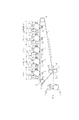
図1及び2に、本発明に係る画像形成装置の一例の縦断面図を示す。 1 and 2 are longitudinal sectional views of an example of an image forming apparatus according to the present invention.
同図に示す画像形成装置は、中間転写体としての中間転写ベルト7の移動方向に沿って5個の画像形成ユニットY・M・C・K・Sを配置した、自動両面印刷機構(不図示)を備えたフルカラーの画像形成装置である。トナーには、平均粒径が6μmの二成分非磁性マイナス帯電トナーを使用している。
The image forming apparatus shown in the figure has an automatic duplex printing mechanism (not shown) in which five image forming units Y, M, C, K, and S are arranged along the moving direction of an
同図に示す画像形成装置は、色の異なるトナー像を形成する4個の画像形成ユニット、すなわち、イエロートナー像、マゼンタトナー像、シアントナー像、ブラックトナー像をそれぞれ形成する画像形成ユニットY・M・C・Kを備え、さらに画像形成ユニットSを備えている。画像形成ユニットSは、本装置のイエロートナー、マゼンタトナー、シアントナー、ブラックトナーの組合せでは再現することができない色を形成するためのトナーや、会社のロゴマークのように色味が厳密に規定されている色のための特色トナーや、画像の光沢感制御、画像の保護等のための透明トナーなど、特殊機能トナーのために備えられている。本実施例では、画像形成ユニットSを接着用トナーのために使用した。これらの画像形成ユニットY・M・C・K・Sは、トナーが異なる点を除いて、ほぼ同じ電子写真プロセス構成、作用である。 The image forming apparatus shown in the figure includes four image forming units that form toner images of different colors, that is, image forming units Y and Y that respectively form a yellow toner image, a magenta toner image, a cyan toner image, and a black toner image. The image forming unit S is further provided. The image forming unit S strictly defines the color tone such as a toner for forming a color that cannot be reproduced by the combination of yellow toner, magenta toner, cyan toner, and black toner of this apparatus, or a company logo mark. It is provided for special function toners such as special color toners for the colors being used, and transparent toners for image gloss control, image protection, and the like. In this embodiment, the image forming unit S is used for the adhesive toner. These image forming units Y, M, C, K, and S have substantially the same electrophotographic process configuration and operation except that the toner is different.
まず、本実施例で使用するトナーについて説明する。なお、磁性キャリアには、公知のものを使用した。 First, the toner used in this embodiment will be described. A known magnetic carrier was used.
画像形成用トナーは、ポリエステル樹脂100重量部、パラフィンワックス6重量部、公知の負帯電性電荷制御剤2.0重量部、負帯電性疎水性シリカ1.5重量部の組成で、公知のブラック、マゼンタ、シアン、イエローの各顔料を定着画像の光学濃度を維持するのに必要な量配合した。トナーは公知の製造方法により製造した。この画像形成用トナーの本実施例の画像形成装置における定着適正温度は、各色とも160〜190℃であった。 The toner for image formation has a composition of 100 parts by weight of a polyester resin, 6 parts by weight of paraffin wax, 2.0 parts by weight of a known negatively chargeable charge control agent, and 1.5 parts by weight of a negatively chargeable hydrophobic silica. , Magenta, cyan, and yellow pigments were blended in amounts necessary to maintain the optical density of the fixed image. The toner was manufactured by a known manufacturing method. The proper fixing temperature of this image forming toner in the image forming apparatus of this embodiment was 160 to 190 ° C. for each color.
ここで言う定着適正温度とは、高温での定着ローラオフセット温度の上限温度、低温での転写材に対するトナーの定着性を満たすための下限温度を定着ローラの表面温度で表したものである。 The proper fixing temperature referred to here is the upper limit temperature of the fixing roller offset temperature at a high temperature and the lower limit temperature for satisfying the fixability of the toner to the transfer material at a low temperature as the surface temperature of the fixing roller.
定着性は、定着後の転写材上のトナー像を50g/cm2の加重をかけたシルボン紙で往復5回摺擦して摺擦前後のトナー像の反射濃度低下率を測定することで評価し、20%を定着適正温度の下限温度とした。定着性はトナーと転写材の接着力を示す数値であるが、トナー同士の接着力にも相関があった。 Fixability is evaluated by measuring the rate of decrease in reflection density of the toner image before and after rubbing by sliding the toner image on the transfer material after fixing back and forth five times with sylbon paper applied with a weight of 50 g / cm 2. 20% was set as the lower limit temperature of the proper fixing temperature. The fixability is a numerical value indicating the adhesive force between the toner and the transfer material, but has a correlation with the adhesive force between the toners.
接着用トナーは、低温での軟化性、高温での耐オフセット性の向上のため、パラフィンワックスを12重量部に増量し、ワックス増量による耐ブロッキング性の低下、流動性の低下を補い、さらに高温での耐オフセット性を向上させるために負帯電性疎水性シリカを5.0重量部に増量した。顔料を除くその他の成分は画像形成トナーと同じとした。この接着用トナーの本実施例の画像形成装置における定着適正温度は110〜190℃であった。 Adhesive toner is increased to 12 parts by weight of paraffin wax to improve softness at low temperature and offset resistance at high temperature, and compensates for the decrease in blocking resistance and fluidity due to the increased amount of wax. In order to improve the anti-offset property, the negatively chargeable hydrophobic silica was increased to 5.0 parts by weight. Other components except the pigment were the same as those of the image forming toner. The proper fixing temperature of the adhesive toner in the image forming apparatus of this example was 110 to 190 ° C.
ワックスと負帯電性疎水性シリカの増量により、感光体上の潜像の再現性が悪化したが、転写材の接着部への接着用トナー像の形成には問題なかった。 Although the reproducibility of the latent image on the photoconductor deteriorated due to the increase of the wax and the negatively chargeable hydrophobic silica, there was no problem in forming an adhesive toner image on the adhesive portion of the transfer material.
次に、本実施例の画像形成装置の構成について説明する。 Next, the configuration of the image forming apparatus of this embodiment will be described.
各画像形成ユニットY・M・C・K・Sにおいて、1は像担持体としてのドラム型の電子写真感光体(以下、感光体と記す)であり、駆動手段(不図示)によって矢印方向(逆時計回り)に回転駆動される。感光体1は、導電性基層上に光導電層を設けてなっており、有機感光体(OPC)やアモルファスシリコン感光体、セレン感光体等が使用できる。本実施形態では、有機感光体(OPC)を使用した。 In each of the image forming units Y, M, C, K, and S, reference numeral 1 denotes a drum-type electrophotographic photosensitive member (hereinafter referred to as a photosensitive member) as an image carrier, and is driven in the direction of the arrow (not shown) by a driving unit (not shown). It is driven to rotate counterclockwise. The photoconductor 1 is provided with a photoconductive layer on a conductive base layer, and an organic photoconductor (OPC), an amorphous silicon photoconductor, a selenium photoconductor, or the like can be used. In this embodiment, an organic photoreceptor (OPC) is used.
2は帯電手段であり、感光体1の表面を所定の極性及び、電位に一様に帯電する。帯電手段としては、スコロトロン帯電器や帯電ローラ、磁気ブラシ等が使用できる。本実施形態では、スコロトロン帯電器を使用し、感光体1をマイナス極性の所定電位に帯電した。
A
3は露光手段であり、感光体1の回転方向において、帯電手段2の下流側に配置され、帯電手段2で一様に帯電された感光体1の表面を画像情報に基づき光走査し、感光体1上に静電潜像を形成する。露光手段としては、レーザースキャナやLEDアレイ等が使用できる。本実施形態では、レーザースキャナを使用した。
An
4は現像器であり、感光体1の回転方向において、露光手段3の下流側に配置され、感光体1上の静電潜像をトナーで現像する。本実施形態では、上述の二成分非磁性マイナス帯電トナーにより、感光体1上の静電潜像を反転現像した。
Reference numeral 4 denotes a developing unit, which is disposed on the downstream side of the
5は一次転写手段であり、一次転写位置T1で中間転写ベルト7を中にして感光体1に対向する位置に配置され、一次転写手段5の転写電界により、中間転写ベルト7上に感光体1上のトナー像を一次転写する。一次転写手段としては、スコロトロン転写帯電器や転写ローラ、転写ブレード、転写ブラシ等を使用できる。本実施形態では、スコロトロン転写帯電器を使用し、プラスの転写電界により感光体1上のトナー像を中間転写ベルト7上に一次転写した。
6は感光体クリーニング手段であり、転写手段5で中間転写ベルト7に転写されなかった転写残トナーを感光体1の表面から除去する。感光体クリーニング手段としては、クリーニングブレード、ブラシローラ等が使用できる。本実施形態では、デュロメータA硬度70で3mm厚のウレタン材質のクリーニングブレードを使用した。
A
上述の動作が、5つの画像形成ユニットY・M・C・K・Sにおいておこなわれ、中間転写ベルト7上に、画像形成ユニットYで形成されるイエロートナー像、画像形成ユニットMで形成されるマゼンタトナー像、画像形成ユニットCで形成されるシアントナー像、画像形成ユニットKで形成されるブラックトナー像、画像形成ユニットSで形成される接着用トナー像が、各画像形成ユニットの一次転写部T1において順に重畳されて一次転写される。これにより中間転写ベルト7上にはイエロートナー、マゼンタトナー、シアントナー、ブラックトナーの各像の重ね合わせからなる未定着のフルカラートナー画像が合成形成されるとともに、接着用トナー像が形成される。
The above-described operation is performed in the five image forming units Y, M, C, K, and S, and the yellow toner image formed by the image forming unit Y and the image forming unit M are formed on the
中間転写体である中間転写ベルト7は、駆動ローラ71、従動ローラ72、73で懸架され、各画像形成ユニットY・M・C・K・Sの感光体1に接触して矢印の方向に回転駆動している。
The
中間転写ベルト7には、ポリエステル、フッ素樹脂、ポリフェニレンサルファイド、ポリアミドイミド、ポリイミド、ポリエーテルケトン、ポリカーボネート等の樹脂を使用できる。電気抵抗は、体積抵抗率が106〜1013Ω・cm、表面抵抗率が108〜1014Ω/□が適しており、体積抵抗率が108〜1011Ω・cm、表面抵抗率が1010〜1013Ω/□がより適している。本実施形態では、公知の方法により電気抵抗を体積抵抗率109Ω・cm、表面抵抗率1011Ω/□に調整した厚み90μmの無端ポリイミドベルトを使用した。電気抵抗は、温度23℃、相対湿度50%RHの環境で、測定器はアドバンテスト製R8340A、プローブには主電極外径50mm、ガード電極70mmのものを使用し、印加電圧100V、チャージ時間10秒の条件で測定した。
For the
8は二次転写手段であり、二次転写位置T2で中間転写ベルト7を中にして従動ローラ72に対向する位置に配置される。二次転写手段8の転写電界により、給紙部(不図示)から中間転写ベルト7上のトナー像にタイミングに合わせて二次転写位置T2に導入された転写材Pに中間転写ベルト7上のトナー像を二次転写する。二次転写手段としては、スコロトロン転写帯電器や転写ローラ、転写ブレード、転写ブラシ等が使用できる。本実施形態では、半導電性の発泡ゴム層を金属の軸上に形成した転写ローラを使用し、プラスの転写電界により中間転写ベルト7上のトナー像を転写材P上に二次転写した。
A secondary transfer unit 8 is disposed at a secondary transfer position T2 at a position facing the driven roller 72 with the
9は中間転写ベルトクリーニング手段であり、中間転写ベルト上の転写材に転写されずに残った転写残トナーを除去する。クリーニングローラ、クリーニングブレード、クリーニングウェッブ等が使用できる。本実施形態では、デュロメータA硬度75で2mm厚のウレタン材質のクリーニングブレードを使用した。 An intermediate transfer belt cleaning unit 9 removes transfer residual toner that is not transferred to the transfer material on the intermediate transfer belt. A cleaning roller, a cleaning blade, a cleaning web, or the like can be used. In this embodiment, a cleaning blade made of a urethane material having a durometer A hardness of 75 and a thickness of 2 mm is used.
10は定着手段であり、転写材上のトナー像を加熱、加圧し、転写材上に定着する。
A fixing
定着ローラ101及び加圧ローラ102としては、金属ローラ上にフッ素ゴム、シリコーンゴム等の弾性層、表層にトナーに対して高い離型性を有するPFA、PTFE等のフッ素樹脂、シリコーン樹脂等の材料が積層されたものを使用できる。定着ローラ101の内部にはヒータが配置され、温度が制御される。本実施形態では、アルミニウム合金の中空ローラ上に弾性層として厚み2mmのシリコーンゴム、表層に50μmのPFAを積層した外径60mmの定着ローラ101及び加圧ローラ102で定着器を構成した。また、定着ローラ101の内部にはヒータとしてハロゲンランプを配置し、不図示の表面温度センサーで表面温度を検知し、表面温度を制御した。
As the fixing
11は中折装置であり、画像形成装置にオンライン接続され、画像形成装置から搬送されてきたトナーが形成され、定着された転写材Pを接着用トナーにより接着部が形成された面が内側になるように指定の位置で折り曲げる。本実施例では公知の中折装置を使用した。 Reference numeral 11 denotes a half-folding apparatus, which is connected online to the image forming apparatus, formed with the toner conveyed from the image forming apparatus, and the surface on which the bonding portion is formed on the fixed transfer material P by the bonding toner. Bend at the specified position so that In this embodiment, a known folding device is used.
12は密封装置である。中折装置11で接着用トナーにより接着部が形成された面が内側に折り曲げられた転写材Pを加熱、加圧し、接着部を接着する。本実施例の密封装置に求められる機能は、画像形成装置の定着器と同じである。本実施形態では、本画像形成装置の定着手段10を流用して使用した。
Reference numeral 12 denotes a sealing device. The transfer material P in which the surface on which the adhesive portion is formed by the adhesive toner in the middle folding device 11 is bent inward is heated and pressed to bond the adhesive portion. The function required for the sealing device of this embodiment is the same as that of the fixing device of the image forming apparatus. In this embodiment, the fixing
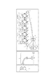
続けて、上述の自動両面印刷機構を備えた画像形成装置における画像形成方法について、図3に示す保険見積書の作成を例に、図4で示したステップに基づき説明する。 Next, an image forming method in the image forming apparatus provided with the above-described automatic duplex printing mechanism will be described based on the steps shown in FIG.
ステップ1は電子的な画像情報に基づき、転写材の1面目に画像形成トナー像を形成する工程である。本実施形態では宛名、社名等を印刷した。 Step 1 is a step of forming an image forming toner image on the first surface of the transfer material based on electronic image information. In this embodiment, the address, company name, etc. are printed.
ステップ2は電子的な画像情報に基づき、転写材の2面目に画像形成トナー像、接着用トナー像を形成する工程である。本実施形態では、保険見積書の内容を印刷し、接着用トナーにより接着部Aを形成した。
接着用トナーは画像形成トナーより低温で軟化する特性を付与しているが、増量されたワックス及びシリカの効果で高温での定着ローラオフセット性が画像形成トナーと同等であるため、画像形成トナーと同じ定着ローラ温度で定着することができる。本実施例では180℃に設定した。 The adhesive toner has the property of being softened at a lower temperature than the image forming toner. However, since the offset roller fixing property at a high temperature is equivalent to that of the image forming toner due to the effect of the increased amount of wax and silica, Fixing can be performed at the same fixing roller temperature. In this example, the temperature was set to 180 ° C.
ステップ3は、転写材を折り曲げる工程である。定着後の転写材は不図示の反転装置により接着用トナー像を形成した面を下向きにして中折装置11に搬送され、接着用トナー像を形成した面が内側になるように折り曲げられる。本実施形態では、保険見積書の中央の一点鎖線で接着部Aが内側になるように折り曲げた。
ステップ4は密封する工程である。折り曲げられた転写材は密封装置12に搬送され、加熱されることで接着用トナーに接着性が発現し、加圧されることで密封される。密封に最適な温度は必要とされる接着力や紙の熱容量で異なるため、密封装置の定着ローラ温度は本体制御部で設定変更することができる。本実施形態では125℃に設定した。 Step 4 is a process of sealing. The folded transfer material is conveyed to the sealing device 12 and is heated to develop adhesiveness in the adhesive toner, and is sealed by being pressurized. Since the optimum temperature for sealing differs depending on the required adhesive force and the heat capacity of paper, the fixing roller temperature of the sealing device can be changed by the main body control unit. In this embodiment, the temperature is set to 125 ° C.
上述の方法で作成された保険見積書は、接着部Aで接着して密封されており、ミシン目の所で接着部を切り取ることで開封することができた。また、画像形成トナーで作成されたトナー像に対抗面へのオフセット、トナー像の変形等の画像劣化は発生しなかった。 The insurance quote prepared by the above-described method is sealed by bonding with the bonding portion A, and can be opened by cutting the bonding portion at the perforation. In addition, image deterioration such as offset to the opposing surface and deformation of the toner image did not occur in the toner image created with the image forming toner.
本実施例では、接着用トナーによる接着部Aの形成を2面目でおこなったが、1面目に接着用トナー像を形成することも可能である。 In this embodiment, the adhesive portion A is formed with the adhesive toner on the second surface, but an adhesive toner image can also be formed on the first surface.
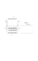
図5に、本発明に係る画像形成装置の一例の縦断面図を示す。 FIG. 5 shows a longitudinal sectional view of an example of the image forming apparatus according to the present invention.
同図に示す画像形成装置は、感光体、帯電手段、現像手段、クリーニング手段、トナー容器が1体となって交換可能ないわゆるカートリッジ方式の自動両面印刷機構(不図示)を備えた白黒の画像形成装置である。トナーには、平均粒径が7μmの一成分磁性マイナス帯電トナーを使用している。 The image forming apparatus shown in the figure is a black and white image provided with a so-called cartridge type automatic duplex printing mechanism (not shown) that can be replaced as a single unit including a photosensitive member, a charging unit, a developing unit, a cleaning unit, and a toner container. Forming device. As the toner, a one-component magnetic minus charged toner having an average particle diameter of 7 μm is used.
まず、本実施例で使用するトナーについて説明する。 First, the toner used in this embodiment will be described.
画像形成用トナーは、スチレン系樹脂100重量部、パラフィンワックス5重量部、マグネタイト80重量部、公知の負帯電性電荷制御剤2.0重量部、負帯電性疎水性シリカ1.0重量部の組成で、公知の製造方法により製造した。この画像形成用トナーの本実施例の画像形成装置における定着適正温度は160〜200℃であった。 The toner for image formation comprises 100 parts by weight of a styrene resin, 5 parts by weight of paraffin wax, 80 parts by weight of magnetite, 2.0 parts by weight of a known negatively chargeable charge control agent, and 1.0 part by weight of negatively chargeable hydrophobic silica. The composition was manufactured by a known manufacturing method. The proper fixing temperature of the image forming toner in the image forming apparatus of this embodiment was 160 to 200 ° C.
接着用トナーは、低温での軟化性の向上のため、公知のホットメルト接着剤を10重量部配合し、ホットメルト接着剤の配合による耐ブロッキング性の低下、流動性の低下を補い、高温での耐オフセット性を向上させるために負帯電性疎水性シリカを3.0重量部に増量した。その他の成分は画像形成トナーと同じとした。この接着用トナーの本実施例の画像形成装置における定着適正温度は130〜160℃であった。ホットメルト接着剤の配合と負帯電性疎水性シリカの増量により、感光体上の潜像の再現性が悪化したが、転写材の接着部への接着用トナー像の形成には問題なかった。 To improve the softening property at low temperature, the adhesive toner is formulated with 10 parts by weight of a known hot melt adhesive, which compensates for the decrease in blocking resistance and fluidity due to the blending of the hot melt adhesive. In order to improve the offset resistance, the amount of the negatively charged hydrophobic silica was increased to 3.0 parts by weight. The other components were the same as those of the image forming toner. The proper fixing temperature of the adhesive toner in the image forming apparatus of this embodiment was 130 to 160 ° C. Although the reproducibility of the latent image on the photoconductor deteriorated due to the blending of the hot melt adhesive and the increase in the amount of the negatively chargeable hydrophobic silica, there was no problem in forming a toner image for adhesion on the adhesive portion of the transfer material.
次に、本実施例の画像形成装置の構成について説明する。 Next, the configuration of the image forming apparatus of this embodiment will be described.
1は像担持体としての感光体であり、駆動手段(不図示)によって矢印方向(時計回り)に回転駆動される。感光体1は、導電性基層上に光導電層を設けてなっており、有機感光体(OPC)やアモルファスシリコン感光体、セレン感光体等が使用できる。本実施形態では、有機感光体(OPC)を使用した。 Reference numeral 1 denotes a photoconductor as an image carrier, which is rotationally driven in a direction of an arrow (clockwise) by a driving unit (not shown). The photoconductor 1 is provided with a photoconductive layer on a conductive base layer, and an organic photoconductor (OPC), an amorphous silicon photoconductor, a selenium photoconductor, or the like can be used. In this embodiment, an organic photoreceptor (OPC) is used.
2は帯電手段であり、感光体1の表面を所定の極性及び、電位に一様に帯電する。帯電手段としては、スコロトロン帯電器や帯電ローラ、磁気ブラシ等が使用できる。本実施形態では、導電性の発泡ゴム層を金属の軸上に形成し、その上に、300μmの誘電層、10μmの保護層の順に塗工した帯電ローラを使用し、感光体1をマイナス極性の所定電位に帯電した。
A charging
3は露光手段であり、感光体1の回転方向において、帯電手段2の下流側に配置され、帯電手段2で一様に帯電された感光体1の表面を画像情報に基づき光走査し、感光体1上に静電潜像を形成する。露光手段としては、レーザースキャナやLEDアレイ等が使用できる。本実施形態では、レーザースキャナを使用した。
An
4は現像器であり、感光体1の回転方向において、露光手段3の下流側に配置され、感光体1上の静電潜像をトナーで現像する。本実施形態では、現像器内部の磁界発生手段を有して回転するトナー担持体である現像スリーブ上にトナーを薄層で保持し、感光体1と非接触の状態で対向させた位置で、現像スリーブに印加したDCを重畳したACバイアスにより、トナーを感光体1上に飛翔させる、いわゆる磁性ジャンピング現像方式で、上述の一成分磁性マイナス帯電トナーにより、感光体1上の静電潜像を反転現像した。
Reference numeral 4 denotes a developing unit, which is disposed on the downstream side of the
5は転写手段であり、感光体1の対向位置に配置され、転写手段5の転写電界により、感光体1上のトナー像を転写材に転写する。転写手段としては、スコロトロン転写帯電器や転写ローラ、転写ブレード、転写ブラシ等を使用できる。本実施形態では、半導電性の発泡ゴム層を金属の軸上に形成した転写ローラを使用し、プラスの転写電界により感光体1上のトナー像を転写材P上に転写した。
A
6は感光体クリーニング手段であり、転写手段5で転写材Pに転写されなかった転写残トナーを感光体1の表面から除去する。感光体クリーニング手段としては、クリーニングブレード、ブラシローラ等が使用できる。本実施形態では、デュロメータA硬度70で1.5mm厚のウレタン材質のクリーニングブレードを使用した。
A
10は定着手段であり、転写材上のトナー像を加熱、加圧し、転写材上に定着する。
A fixing
定着ローラ101及び加圧ローラ102としては、金属ローラ上にフッ素ゴム、シリコーンゴム等の弾性層、表層にトナーに対して高い離型性を有するPFA、PTFE等のフッ素樹脂、シリコーン樹脂等の材料が積層されたものを使用できる。定着ローラ101の内部にはヒータが配置され、温度が制御される。本実施形態では、アルミニウム合金の中空ローラ上に弾性層として厚み2mmのシリコーンゴム、表層に50μmのPFAを積層した外径30mmの定着ローラ101及び加圧ローラ102で定着器を構成した。また、定着ローラ101の内部にはヒータとしてハロゲンランプを配置し、不図示の表面温度センサーで表面温度を検知し、表面温度を制御した。
As the fixing
続けて、上述の自動両面印刷機構を備えた画像形成装置における画像形成方法について、図6に示す給与明細書の作成を例に、図7で示したステップに基づき説明する。 Next, an image forming method in the image forming apparatus provided with the above-described automatic duplex printing mechanism will be described based on the steps shown in FIG.
ステップ1は電子的な画像情報に基づき、転写材の1面目に画像形成トナー像を形成する工程である。本実施形態では、宛名等を印刷した。また、画像形成トナー像形成時の定着ローラの表面温度は190℃に設定した。 Step 1 is a step of forming an image forming toner image on the first surface of the transfer material based on electronic image information. In this embodiment, the address and the like are printed. Further, the surface temperature of the fixing roller at the time of image formation toner image formation was set to 190 ° C.
ステップ2は電子的な画像情報に基づき、転写材の2面目に画像形成トナー像を形成する工程である。本実施形態では、給与明細書の内容を印刷した。
ステップ3は画像形成トナーのカートリッジを接着用トナーのカートリッジに交換工程である。接着用トナーのカートリッジに交換するとカートリッジ側面に配置されているICタグ(不図示)を本体が読み取り、自動的に定着ローラの表面温度設定を接着用トナーの設定に変更する。本実施形態では、定着ローラの表面温度を130℃に設定した。
ステップ4は電子的な画像情報に基づき、接着用トナー像を形成する工程である。本実施形態では、給与明細書の内容を印刷した面に、接着用トナーによる接着部Aを形成した。 Step 4 is a process for forming an adhesive toner image based on electronic image information. In the present embodiment, the adhesive portion A made of adhesive toner is formed on the surface on which the contents of the salary statement are printed.
ステップ5は、転写材を折り曲げる工程である。本実施形態では、給与明細書の中央の一点鎖線で接着部Aが内側になるように手作業により折り曲げた。
ステップ6は、接着用トナーのカートリッジを密封工程で使用するためのトナーが入っていない空のカートリッジに交換する工程である。密封工程用のカートリッジに交換するとカートリッジ側面に配置されているICタグ(不図示)を本体が読み取り、自動的に定着ローラの表面温度設定を密封工程用の設定に変更する。密封に最適な温度は必要される接着力や紙の熱容量で異なるため、密封装置の定着ローラ温度は本体制御部で設定変更することができる。本実施形態では140℃に設定した。
ステップ7は密封する工程である。折り曲げられた転写材を画像形成時と同様に画像形成装置内を通過させ、定着装置により加熱することで接着用トナーに接着性が発現し、加圧されることで密封される。
上述の方法で作成された給与明細書は、接着部Aで接着して密封されており、ミシン目の所で接着部を切り取ることで開封することができた。また、画像形成トナーで作成されたトナー像に対抗面へのオフセット、トナー像の変形等の画像劣化は発生しなかった。 The pay statement prepared by the above-described method was sealed by bonding with the bonding portion A, and could be opened by cutting the bonding portion at the perforation. In addition, image deterioration such as offset to the opposing surface and deformation of the toner image did not occur in the toner image created with the image forming toner.
図8に、本発明に係る画像形成装置の一例の縦断面図を示す。 FIG. 8 shows a longitudinal sectional view of an example of the image forming apparatus according to the present invention.
同図に示す画像形成装置は、中間転写体としての中間転写ベルト7の移動方向に沿って4個の画像形成ユニットR・G・K・Sを配置した3色の自動両面印刷機構(不図示)を備えた画像形成装置である。トナーには、平均粒径が6μmの二成分非磁性マイナス帯電トナーを使用している。
The image forming apparatus shown in the figure has a three-color automatic duplex printing mechanism (not shown) in which four image forming units R, G, K, and S are arranged along the moving direction of an
同図に示す画像形成装置は、色の異なるトナー像を形成する3個の画像形成ユニット、すなわち、特色レッドトナー像、特色グリーントナー像、ブラックトナー像をそれぞれ形成する画像形成ユニットR・G・Kを備え、さらに接着用トナーの画像形成ユニットSを備えている。画像形成ユニットR・Gの特色レッドトナーと特色グリーントナーは会社のロゴマークの色を忠実に再現するために用意したトナーである。これらの画像形成ユニットR・G・K・Sは、トナーが異なる点を除いて、ほぼ同じ電子写真プロセス構成、作用である。 The image forming apparatus shown in FIG. 1 includes three image forming units that form toner images of different colors, that is, image forming units R, G, and S that respectively form a special color red toner image, a special color green toner image, and a black toner image. K, and further an image forming unit S for adhesion toner. The special color red toner and special color green toner of the image forming units R and G are toners prepared to faithfully reproduce the color of the company logo mark. These image forming units R, G, K, and S have substantially the same electrophotographic process configuration and operation except that the toner is different.
まず、本実施例で使用するトナーについて説明する。なお、磁性キャリアには、公知のものを使用した。 First, the toner used in this embodiment will be described. A known magnetic carrier was used.
画像形成用トナーは、ポリエステル樹脂100重量部、パラフィンワックス6重量部、公知の負帯電性電荷制御剤2.0重量部、負帯電性疎水性シリカ1.5重量部の組成で、公知の各顔料を定着画像の光学濃度を維持するのに必要な量配合し、ブラック、特色レッド、特色グリーンのトナーを公知の製造方法により製造した。この画像形成用トナーの本実施例の画像形成装置における定着適正温度は、各色とも160〜190℃であった。 The toner for image formation has a composition of 100 parts by weight of a polyester resin, 6 parts by weight of paraffin wax, 2.0 parts by weight of a known negatively chargeable charge control agent, and 1.5 parts by weight of negatively chargeable hydrophobic silica. The pigment was blended in an amount necessary to maintain the optical density of the fixed image, and toners of black, special color red, and special color green were produced by a known production method. The proper fixing temperature of this image forming toner in the image forming apparatus of this embodiment was 160 to 190 ° C. for each color.
接着用トナーは、低温での軟化性、高温での耐オフセット性の向上のため、パラフィンワックスを12重量部に増量し、ワックス増量による耐ブロッキング性の低下、流動性の低下を補い、さらに高温での耐オフセット性を向上させるために負帯電性疎水性シリカを5.0重量部に増量した。顔料を除くその他の成分は画像形成トナーと同じとした。この接着用トナーの本実施例の画像形成装置における定着適正温度は110〜190℃であった。 Adhesive toner is increased to 12 parts by weight of paraffin wax to improve softness at low temperature and offset resistance at high temperature, and compensates for the decrease in blocking resistance and fluidity due to the increased amount of wax. In order to improve the anti-offset property, the negatively chargeable hydrophobic silica was increased to 5.0 parts by weight. Other components except the pigment were the same as those of the image forming toner. The proper fixing temperature of the adhesive toner in the image forming apparatus of this example was 110 to 190 ° C.
ワックスと負帯電性疎水性シリカの増量により、感光体上の潜像の再現性が悪化したが、転写材の接着部への接着用トナー像の形成には問題なかった。 Although the reproducibility of the latent image on the photoconductor deteriorated due to the increase of the wax and the negatively chargeable hydrophobic silica, there was no problem in forming an adhesive toner image on the adhesive portion of the transfer material.
次に、本実施例の画像形成装置の構成について説明する。 Next, the configuration of the image forming apparatus of this embodiment will be described.
各画像形成ユニットR・G・K・Sにおいて、1は像担持体としての感光体であり、駆動手段(不図示)によって矢印方向(逆時計回り)に回転駆動される。感光体1は、導電性基層上に光導電層を設けてなっており、有機感光体(OPC)やアモルファスシリコン感光体、セレン感光体等が使用できる。本実施形態では、有機感光体(OPC)を使用した。 In each of the image forming units R, G, K, and S, reference numeral 1 denotes a photoconductor as an image carrier, which is rotationally driven in an arrow direction (counterclockwise) by a driving unit (not shown). The photoconductor 1 is provided with a photoconductive layer on a conductive base layer, and an organic photoconductor (OPC), an amorphous silicon photoconductor, a selenium photoconductor, or the like can be used. In this embodiment, an organic photoreceptor (OPC) is used.
2は帯電手段であり、感光体1の表面を所定の極性及び、電位に一様に帯電する。帯電手段としては、スコロトロン帯電器や帯電ローラ、磁気ブラシ等が使用できる。本実施形態では、スコロトロン帯電器を使用し、感光体1をマイナス極性の所定電位に帯電した。
A charging
3は露光手段であり、感光体1の回転方向において、帯電手段2の下流側に配置され、帯電手段2で一様に帯電された感光体1の表面を画像情報に基づき光走査し、感光体1上に静電潜像を形成する。露光手段としては、レーザースキャナやLEDアレイ等が使用できる。本実施形態では、レーザースキャナを使用した。
An
4は現像器であり、感光体1の回転方向において、露光手段3の下流側に配置され、感光体1上の静電潜像をトナーで現像する。本実施形態では、上述の二成分非磁性マイナス帯電トナーにより、感光体1上の静電潜像を反転現像した。
Reference numeral 4 denotes a developing unit, which is disposed on the downstream side of the
5は一次転写手段であり、一次転写位置T1で中間転写ベルト7を中にして感光体1に対向する位置に配置され、一次転写手段5の転写電界により、中間転写ベルト7上に感光体1上のトナー像を一次転写する。一次転写手段としては、スコロトロン転写帯電器や転写ローラ、転写ブレード、転写ブラシ等を使用できる。本実施形態では、スコロトロン転写帯電器を使用し、プラスの転写電界により感光体1上のトナー像を中間転写ベルト7上に一次転写した。
6は感光体クリーニング手段であり、転写手段5で中間転写ベルト7に転写されなかった転写残トナーを感光体1の表面から除去する。感光体クリーニング手段としては、クリーニングブレード、ブラシローラ等が使用できる。本実施形態では、デュロメータA硬度70で3mm厚のウレタン材質のクリーニングブレードを使用した。
A
上述の動作が、4つの画像形成ユニットR・G・K・Sにおいておこなわれ、中間転写ベルト7上に、画像形成ユニットRで形成される特色レッドトナー像、画像形成ユニットGで形成される特色グリーントナー像、画像形成ユニットKで形成されるブラックトナー像、画像形成ユニットSで形成される接着用トナー像が、各画像形成ユニットの一次転写部T1において順に重畳されて一次転写される。これにより中間転写ベルト7上には特色レッドトナー、特色グリーントナー、ブラックトナーによる未定着の3色のトナー画像が形成されるとともに、接着用トナー像が形成される。
The above-described operation is performed in the four image forming units R, G, K, and S, and the special color red toner image formed by the image forming unit R and the special color formed by the image forming unit G on the
中間転写体である中間転写ベルト7は、駆動ローラ71、従動ローラ72、73で懸架され、各画像形成ユニットR・G・K・Sの感光体1に接触して矢印の方向に回転駆動している。中間転写ベルト7には、ポリエステル、フッ素樹脂、ポリフェニレンサルファイド、ポリアミドイミド、ポリイミド、ポリエーテルケトン、ポリカーボネート等の樹脂を使用できる。電気抵抗は、体積抵抗率が106〜1013Ω・cm、表面抵抗率が108〜1014Ω/□が適しており、体積抵抗率が108〜1011Ω・cm、表面抵抗率が1010〜1013Ω/□がより適している。本実施形態では、公知の方法により電気抵抗を体積抵抗率109Ω・cm、表面抵抗率1011Ω/□に調整した厚み90μmの無端ポリイミドベルトを使用した。
The
8は二次転写手段であり、二次転写位置T2で中間転写ベルト7を中にして従動ローラ72に対向する位置に配置される。二次転写手段8の転写電界により、給紙部(不図示)から中間転写ベルト7上のトナー像にタイミングに合わせて二次転写位置T2に導入された転写材Pに中間転写ベルト7上のトナー像を二次転写する。二次転写手段としては、スコロトロン転写帯電器や転写ローラ、転写ブレード、転写ブラシ等が使用できる。本実施形態では、半導電性の発泡ゴム層を金属の軸上に形成した転写ローラを使用し、プラスの転写電界により中間転写ベルト7上のトナー像を転写材P上に二次転写した。
A secondary transfer unit 8 is disposed at a secondary transfer position T2 at a position facing the driven roller 72 with the
9は中間転写ベルトクリーニング手段であり、中間転写ベルト上の転写材に転写されずに残った転写残トナーを除去する。クリーニングローラ、クリーニングブレード、クリーニングウェッブ等が使用できる。本実施形態では、デュロメータA硬度75で2mm厚のウレタン材質のクリーニングブレードを使用した。 An intermediate transfer belt cleaning unit 9 removes transfer residual toner that is not transferred to the transfer material on the intermediate transfer belt. A cleaning roller, a cleaning blade, a cleaning web, or the like can be used. In this embodiment, a cleaning blade made of a urethane material having a durometer A hardness of 75 and a thickness of 2 mm is used.
10は定着手段であり、転写材上のトナー像を加熱、加圧し、転写材上に定着する。
A fixing
定着ローラ101及び加圧ローラ102としては、金属ローラ上にフッ素ゴム、シリコーンゴム等の弾性層、表層にトナーに対して高い離型性を有するPFA、PTFE等のフッ素樹脂、シリコーン樹脂等の材料が積層されたものを使用できる。定着ローラ101の内部にはヒータが配置され、温度が制御される。本実施形態では、アルミニウム合金の中空ローラ上に弾性層として厚み2mmのシリコーンゴム、表層に50μmのPFAを積層した外径60mmの定着ローラ101及び加圧ローラ102で定着器を構成した。また、定着ローラ101の内部にはヒータとしてハロゲンランプを配置し、不図示の表面温度センサーで表面温度を検知し、表面温度を制御した。
As the fixing
本実施例の画像形成装置には後処理装置として、実施例1に記載の中折装置11と密封装置12がオンライン接続される。 The image forming apparatus according to the present embodiment is connected to the middle folding device 11 and the sealing device 12 described in the first embodiment as post-processing devices.
続けて、上述の自動両面印刷機構を備えた画像形成装置における画像形成方法について、図9に示す辞令の作成を例に、図4で示したステップに基づき説明する。 Next, an image forming method in the image forming apparatus provided with the above-described automatic duplex printing mechanism will be described based on the steps shown in FIG.
ステップ1は電子的な画像情報に基づき、転写材の1面目に画像形成トナー像を形成する工程である。本実施形態では宛名、特色トナーによる会社のロゴマーク等を印刷した。 Step 1 is a step of forming an image forming toner image on the first surface of the transfer material based on electronic image information. In this embodiment, an address, a company logo mark by special color toner, and the like are printed.
ステップ2は電子的な画像情報に基づき、転写材の2面目に画像形成トナー像、接着用トナー像を形成する工程である。本実施形態では、辞令の内容を印刷し、接着用トナーにより接着部Aを形成した。
接着用トナーは画像形成トナーより低温で軟化する特性を付与しているが、増量されたワックス及びシリカの効果で高温での定着ローラオフセット性が画像形成トナーと同等であるため、画像形成トナーと同じ定着ローラ温度で定着することができる。本実施例では180℃に設定した。 The adhesive toner has the property of being softened at a lower temperature than the image forming toner. However, since the offset roller fixing property at a high temperature is equivalent to that of the image forming toner due to the effect of the increased amount of wax and silica, Fixing can be performed at the same fixing roller temperature. In this example, the temperature was set to 180 ° C.
ステップ3は、転写材を折り曲げる工程である。定着後の転写材は不図示の反転装置により接着用トナー像を形成した面を下向きにして実施例1記載の中折装置に搬送され、接着用トナー像を形成した面が内側になるように折り曲げられる。本実施形態では、辞令の中央の一点鎖線で接着部Aが内側になるように折り曲げた。
ステップ4は密封する工程である。折り曲げられた転写材は実施例1記載の密封装置に搬送され、加熱されることで接着用トナーに接着性が発現し、加圧されることで密封される。密封に最適な温度は必要とされる接着力や紙の熱容量で異なるため、密封装置の定着ローラ温度は本体制御部で設定変更することができる。本実施形態では、接着部Aの部分で剥離が可能なように実施例1の125℃に対して、20℃低い、105℃に設定した。 Step 4 is a process of sealing. The folded transfer material is transported to the sealing device described in the first embodiment, and is heated to exhibit adhesiveness in the adhesive toner, and is sealed by being pressurized. Since the optimum temperature for sealing differs depending on the required adhesive force and the heat capacity of paper, the fixing roller temperature of the sealing device can be changed by the main body control unit. In the present embodiment, the temperature is set to 105 ° C., which is 20 ° C. lower than 125 ° C. in Example 1 so that peeling can be performed at the adhesive portion A.
上述の方法で作成された辞令は、接着部Aで接着して密封されており、接着部Aを剥離して開封することができた。また、画像形成トナーで作成されたトナー像に対抗面へのオフセット、トナー像の変形等の画像劣化は発生しなかった。 The decree created by the above-described method was sealed by bonding at the bonding portion A, and the bonding portion A was peeled off and opened. In addition, image deterioration such as offset to the opposing surface and deformation of the toner image did not occur in the toner image created with the image forming toner.
本実施例では、接着用トナーによる接着部Aの形成を2面目でおこなったが、1面目に接着用トナー像を形成することも可能である。 In this embodiment, the adhesive portion A is formed with the adhesive toner on the second surface, but an adhesive toner image can also be formed on the first surface.
1 感光体ドラム
2 帯電手段
3 露光手段
4 現像手段
5 転写手段または一次転写手段
6 感光体クリーニング手段
7 中間転写ベルト
71 駆動ローラ
72、73 従動ローラ
8 二次転写手段
9 中間転写ベルトクリーニング手段
10 定着手段
101 定着ローラ
102 加圧ローラ
11 中折装置
12 密封装置
P 転写材
T1 転写ニップまたは一次転写ニップ
T2 二次転写ニップ
DESCRIPTION OF SYMBOLS 1
Claims (2)
シートに形成された画像形成用のトナーと接着用のトナーを第1の温度で加熱して定着する定着工程と、A fixing step of fixing the image forming toner and the adhesive toner formed on the sheet by heating at a first temperature;
前記加熱されたシートを前記接着用のトナーを内側となるよう折りたたむ工程と、Folding the heated sheet so that the adhesive toner is inside;
前記折りたたまれたシートを前記第1の温度よりも低い第2の温度で加熱することで、前記接着用トナーを再溶融させて接着させる工程と、を備える画像形成方法。Heating the folded sheet at a second temperature lower than the first temperature to remelt and bond the adhesive toner.
Priority Applications (2)
| Application Number | Priority Date | Filing Date | Title |
|---|---|---|---|
| JP2004367348A JP4498122B2 (en) | 2004-12-20 | 2004-12-20 | Image forming method |
| US11/304,814 US7260354B2 (en) | 2004-12-20 | 2005-12-16 | Image forming method |
Applications Claiming Priority (1)
| Application Number | Priority Date | Filing Date | Title |
|---|---|---|---|
| JP2004367348A JP4498122B2 (en) | 2004-12-20 | 2004-12-20 | Image forming method |
Publications (3)
| Publication Number | Publication Date |
|---|---|
| JP2006171607A JP2006171607A (en) | 2006-06-29 |
| JP2006171607A5 JP2006171607A5 (en) | 2008-02-14 |
| JP4498122B2 true JP4498122B2 (en) | 2010-07-07 |
Family
ID=36595949
Family Applications (1)
| Application Number | Title | Priority Date | Filing Date |
|---|---|---|---|
| JP2004367348A Expired - Fee Related JP4498122B2 (en) | 2004-12-20 | 2004-12-20 | Image forming method |
Country Status (2)
| Country | Link |
|---|---|
| US (1) | US7260354B2 (en) |
| JP (1) | JP4498122B2 (en) |
Cited By (1)
| Publication number | Priority date | Publication date | Assignee | Title |
|---|---|---|---|---|
| JP2017151323A (en) * | 2016-02-25 | 2017-08-31 | 富士ゼロックス株式会社 | Image forming apparatus |
Families Citing this family (34)
| Publication number | Priority date | Publication date | Assignee | Title |
|---|---|---|---|---|
| US7817953B2 (en) * | 2006-01-17 | 2010-10-19 | Ricoh Company, Limited | Image recording medium, sheet feeding device, and image forming apparatus |
| JP5124098B2 (en) | 2006-03-28 | 2013-01-23 | 株式会社リコー | Transfer belt unit and image forming apparatus |
| JP2008024444A (en) * | 2006-07-21 | 2008-02-07 | Konica Minolta Business Technologies Inc | Paper carrying device, and image forming device |
| JP2008036957A (en) * | 2006-08-07 | 2008-02-21 | Casio Electronics Co Ltd | Apparatus for manufacturing printed bag |
| JP2008107609A (en) * | 2006-10-26 | 2008-05-08 | Ricoh Co Ltd | Method and apparatus for forming image sheet |
| JP5127233B2 (en) * | 2007-01-05 | 2013-01-23 | キヤノン株式会社 | Image forming apparatus and image forming method |
| JP5153500B2 (en) * | 2007-08-02 | 2013-02-27 | キヤノン株式会社 | Sheet processing apparatus and image forming apparatus |
| JP5327426B2 (en) * | 2008-05-16 | 2013-10-30 | 株式会社リコー | Image forming apparatus, image forming method, and print medium |
| JP5235510B2 (en) * | 2008-06-05 | 2013-07-10 | キヤノン株式会社 | Image forming apparatus |
| JP5544811B2 (en) * | 2009-09-30 | 2014-07-09 | 大日本印刷株式会社 | Image output apparatus and image output method |
| US8548371B2 (en) | 2010-05-24 | 2013-10-01 | Eastman Kodak Company | Electrophotographic print binding system |
| US20110286779A1 (en) | 2010-05-24 | 2011-11-24 | Kwarta Brian J | Electrophotographic print binding method and system |
| US8313883B2 (en) * | 2010-05-24 | 2012-11-20 | Eastman Kodak Company | Electrophotographic print binding method |
| JP5610928B2 (en) * | 2010-08-27 | 2014-10-22 | キヤノン株式会社 | Image forming apparatus |
| JP5725404B2 (en) * | 2010-12-17 | 2015-05-27 | 株式会社リコー | Bookbinding system |
| JP2013043751A (en) * | 2011-08-24 | 2013-03-04 | Ricoh Co Ltd | Staple device and image formation apparatus |
| US8904932B2 (en) | 2012-07-26 | 2014-12-09 | Eastman Kodak Company | Producing bound document having inner cover sheet |
| US8870228B2 (en) | 2012-09-26 | 2014-10-28 | Eastman Kodak Company | Bound document having binding strip with spacer |
| US8702127B2 (en) | 2012-09-26 | 2014-04-22 | Eastman Kodak Company | Making bound document having fastener and spacer |
| JP5626422B2 (en) * | 2013-07-26 | 2014-11-19 | 株式会社リコー | Image forming apparatus, image forming method, and print medium |
| JPWO2015104931A1 (en) * | 2014-01-10 | 2017-03-23 | 株式会社リコー | Image forming apparatus |
| JP6299246B2 (en) * | 2014-02-06 | 2018-03-28 | 株式会社リコー | Heating and pressing apparatus, heating and pressing method, and removable information sheet manufacturing apparatus |
| JP6090234B2 (en) * | 2014-05-26 | 2017-03-08 | コニカミノルタ株式会社 | Image forming apparatus and image forming method |
| JP6411978B2 (en) * | 2015-09-24 | 2018-10-24 | 株式会社沖データ | Image forming apparatus |
| US10662356B2 (en) * | 2018-01-18 | 2020-05-26 | Xerox Corporation | Method of using a toner as a printable adhesive |
| US11360416B2 (en) | 2019-12-24 | 2022-06-14 | Canon Kabushiki Kaisha | Image forming apparatus |
| JP7463094B2 (en) * | 2019-12-24 | 2024-04-08 | キヤノン株式会社 | Image forming apparatus and sheet processing apparatus |
| JP7480539B2 (en) | 2020-03-18 | 2024-05-10 | 富士フイルムビジネスイノベーション株式会社 | Printed matter manufacturing method and printed matter manufacturing system |
| US12044997B2 (en) | 2020-07-31 | 2024-07-23 | Canon Kabushiki Kaisha | Image forming apparatus |
| JP7486260B2 (en) | 2020-07-31 | 2024-05-17 | キヤノン株式会社 | Image forming apparatus and bonding apparatus |
| JP7543019B2 (en) | 2020-07-31 | 2024-09-02 | キヤノン株式会社 | Electrophotographic developer set including toner and powder adhesive and method for producing adhesive |
| US11835898B2 (en) | 2020-07-31 | 2023-12-05 | Canon Kabushiki Kaisha | Adhesion apparatus for forming image of powder adhesive, and image forming apparatus |
| JP7527883B2 (en) | 2020-07-31 | 2024-08-05 | キヤノン株式会社 | Image forming device |
| JP2023006021A (en) * | 2021-06-30 | 2023-01-18 | キヤノン株式会社 | Sheet adhesion device |
Citations (7)
| Publication number | Priority date | Publication date | Assignee | Title |
|---|---|---|---|---|
| JPH10133515A (en) * | 1996-10-30 | 1998-05-22 | Ricoh Co Ltd | Image forming device |
| JPH11167348A (en) * | 1997-12-05 | 1999-06-22 | Casio Comput Co Ltd | Security recordable electrophotographic recorder and security recording method |
| JP2000347552A (en) * | 1999-06-09 | 2000-12-15 | Canon Inc | Process cartridge and electrophotographic image forming device |
| JP2002082508A (en) * | 2000-09-05 | 2002-03-22 | Casio Electronics Co Ltd | Image forming device |
| JP2002139882A (en) * | 2000-10-31 | 2002-05-17 | Konica Corp | Color image forming device |
| JP2002148998A (en) * | 2000-11-09 | 2002-05-22 | Niigata Fuji Xerox Manufacturing Co Ltd | Electrophotographic printer and its control method |
| JP2003149994A (en) * | 2001-11-09 | 2003-05-21 | Fuji Xerox Co Ltd | Image forming device |
Family Cites Families (10)
| Publication number | Priority date | Publication date | Assignee | Title |
|---|---|---|---|---|
| DE3508114C1 (en) | 1985-03-07 | 1986-05-22 | O. T. Drescher GmbH, 7255 Rutesheim | Process for gluing products made of paper, foils, etc., in particular label sheets |
| US5213560A (en) * | 1991-05-20 | 1993-05-25 | Roll Systems, Inc. | System and method for manufacturing sealed packages |
| US5361089A (en) * | 1993-07-26 | 1994-11-01 | Hewlett-Packard Company | Method and apparatus for applying an adhesive layer for improved image transfer in electrophotography |
| US5486436A (en) * | 1993-10-15 | 1996-01-23 | The Standard Register Company | Sealable web or sheet product |
| JPH09110051A (en) | 1995-10-16 | 1997-04-28 | Yoshizawa Business Machines Kk | Letter sealing method |
| US6394728B1 (en) * | 1999-05-26 | 2002-05-28 | Hewlett-Packard Company | Binding sheet media using imaging material |
| US6459880B1 (en) * | 2000-11-28 | 2002-10-01 | Xerox Corporation | Document creating system including a film for bonding the document together |
| JP2004093819A (en) * | 2002-08-30 | 2004-03-25 | Seiko Epson Corp | Image forming apparatus and image forming method |
| JP4015521B2 (en) | 2002-10-02 | 2007-11-28 | トッパン・フォームズ株式会社 | Method for forming pressure-sensitive adhesive image |
| US6980767B1 (en) * | 2004-11-11 | 2005-12-27 | Lexmark International, Inc. | Method and apparatus for adhering sheets of print media together by use of toner in an electrophotographic printer |
-
2004
- 2004-12-20 JP JP2004367348A patent/JP4498122B2/en not_active Expired - Fee Related
-
2005
- 2005-12-16 US US11/304,814 patent/US7260354B2/en not_active Expired - Fee Related
Patent Citations (7)
| Publication number | Priority date | Publication date | Assignee | Title |
|---|---|---|---|---|
| JPH10133515A (en) * | 1996-10-30 | 1998-05-22 | Ricoh Co Ltd | Image forming device |
| JPH11167348A (en) * | 1997-12-05 | 1999-06-22 | Casio Comput Co Ltd | Security recordable electrophotographic recorder and security recording method |
| JP2000347552A (en) * | 1999-06-09 | 2000-12-15 | Canon Inc | Process cartridge and electrophotographic image forming device |
| JP2002082508A (en) * | 2000-09-05 | 2002-03-22 | Casio Electronics Co Ltd | Image forming device |
| JP2002139882A (en) * | 2000-10-31 | 2002-05-17 | Konica Corp | Color image forming device |
| JP2002148998A (en) * | 2000-11-09 | 2002-05-22 | Niigata Fuji Xerox Manufacturing Co Ltd | Electrophotographic printer and its control method |
| JP2003149994A (en) * | 2001-11-09 | 2003-05-21 | Fuji Xerox Co Ltd | Image forming device |
Cited By (1)
| Publication number | Priority date | Publication date | Assignee | Title |
|---|---|---|---|---|
| JP2017151323A (en) * | 2016-02-25 | 2017-08-31 | 富士ゼロックス株式会社 | Image forming apparatus |
Also Published As
| Publication number | Publication date |
|---|---|
| US7260354B2 (en) | 2007-08-21 |
| JP2006171607A (en) | 2006-06-29 |
| US20060133871A1 (en) | 2006-06-22 |
Similar Documents
| Publication | Publication Date | Title |
|---|---|---|
| JP4498122B2 (en) | Image forming method | |
| US9063481B2 (en) | Fixing device, image forming apparatus and surface restoration method | |
| JP5241369B2 (en) | Image forming apparatus | |
| EP1965271B1 (en) | Transfer-Fixing Device, Image Forming Apparatus, and Transfer-Fixing Method | |
| JP2009115956A (en) | Image transfer fixation apparatus and image formation apparatus | |
| JPS5858669B2 (en) | How to weld toner images | |
| US8929763B2 (en) | Fusing device and image forming apparatus | |
| US20150227098A1 (en) | Fixing belt, fixing device and image forming apparatus | |
| JP2002287581A (en) | Image forming apparatus, cartridge and image forming method | |
| JP2010204235A (en) | Heat transfer fixing device and image forming apparatus | |
| JP4442265B2 (en) | Glossiness imparting device and image forming apparatus using the same | |
| JP5213388B2 (en) | Image forming apparatus | |
| JP4628918B2 (en) | Developing device and image forming apparatus | |
| JP7467873B2 (en) | Image forming apparatus and image forming method | |
| JP3813458B2 (en) | Belt fixing device and image forming apparatus | |
| JP2000214702A (en) | Fixing device and image forming device | |
| JPH04369677A (en) | Image forming device | |
| JP2013105129A (en) | Image forming apparatus, and image forming method | |
| JP5046807B2 (en) | Image forming apparatus | |
| JP4007530B2 (en) | Multicolor image forming method and multicolor image forming apparatus | |
| JP2006003508A (en) | Image forming apparatus | |
| JP2006195344A (en) | Image forming apparatus | |
| JP2021117426A (en) | Fixing device and image forming apparatus including the same | |
| JPH08160756A (en) | Color image forming device | |
| JP3079751B2 (en) | Multicolor electrophotographic recording device |
Legal Events
| Date | Code | Title | Description |
|---|---|---|---|
| A621 | Written request for application examination |
Free format text: JAPANESE INTERMEDIATE CODE: A621 Effective date: 20071220 |
|
| A521 | Written amendment |
Free format text: JAPANESE INTERMEDIATE CODE: A523 Effective date: 20071227 |
|
| A131 | Notification of reasons for refusal |
Free format text: JAPANESE INTERMEDIATE CODE: A131 Effective date: 20091208 |
|
| A521 | Written amendment |
Free format text: JAPANESE INTERMEDIATE CODE: A523 Effective date: 20100128 |
|
| RD04 | Notification of resignation of power of attorney |
Free format text: JAPANESE INTERMEDIATE CODE: A7424 Effective date: 20100201 |
|
| TRDD | Decision of grant or rejection written | ||
| A01 | Written decision to grant a patent or to grant a registration (utility model) |
Free format text: JAPANESE INTERMEDIATE CODE: A01 Effective date: 20100406 |
|
| A01 | Written decision to grant a patent or to grant a registration (utility model) |
Free format text: JAPANESE INTERMEDIATE CODE: A01 |
|
| A61 | First payment of annual fees (during grant procedure) |
Free format text: JAPANESE INTERMEDIATE CODE: A61 Effective date: 20100413 |
|
| FPAY | Renewal fee payment (event date is renewal date of database) |
Free format text: PAYMENT UNTIL: 20130423 Year of fee payment: 3 |
|
| R150 | Certificate of patent or registration of utility model |
Free format text: JAPANESE INTERMEDIATE CODE: R150 |
|
| FPAY | Renewal fee payment (event date is renewal date of database) |
Free format text: PAYMENT UNTIL: 20130423 Year of fee payment: 3 |
|
| FPAY | Renewal fee payment (event date is renewal date of database) |
Free format text: PAYMENT UNTIL: 20140423 Year of fee payment: 4 |
|
| LAPS | Cancellation because of no payment of annual fees |