JP4497978B2 - Developing device, process cartridge, and image forming apparatus - Google Patents
Developing device, process cartridge, and image forming apparatus Download PDFInfo
- Publication number
- JP4497978B2 JP4497978B2 JP2004097060A JP2004097060A JP4497978B2 JP 4497978 B2 JP4497978 B2 JP 4497978B2 JP 2004097060 A JP2004097060 A JP 2004097060A JP 2004097060 A JP2004097060 A JP 2004097060A JP 4497978 B2 JP4497978 B2 JP 4497978B2
- Authority
- JP
- Japan
- Prior art keywords
- developer
- developing device
- toner
- image
- developing
- Prior art date
- Legal status (The legal status is an assumption and is not a legal conclusion. Google has not performed a legal analysis and makes no representation as to the accuracy of the status listed.)
- Expired - Fee Related
Links
Images


Classifications
-
- G—PHYSICS
- G03—PHOTOGRAPHY; CINEMATOGRAPHY; ANALOGOUS TECHNIQUES USING WAVES OTHER THAN OPTICAL WAVES; ELECTROGRAPHY; HOLOGRAPHY
- G03G—ELECTROGRAPHY; ELECTROPHOTOGRAPHY; MAGNETOGRAPHY
- G03G15/00—Apparatus for electrographic processes using a charge pattern
- G03G15/06—Apparatus for electrographic processes using a charge pattern for developing
- G03G15/08—Apparatus for electrographic processes using a charge pattern for developing using a solid developer, e.g. powder developer
-
- G—PHYSICS
- G03—PHOTOGRAPHY; CINEMATOGRAPHY; ANALOGOUS TECHNIQUES USING WAVES OTHER THAN OPTICAL WAVES; ELECTROGRAPHY; HOLOGRAPHY
- G03G—ELECTROGRAPHY; ELECTROPHOTOGRAPHY; MAGNETOGRAPHY
- G03G9/00—Developers
- G03G9/08—Developers with toner particles
- G03G9/0819—Developers with toner particles characterised by the dimensions of the particles
-
- G—PHYSICS
- G03—PHOTOGRAPHY; CINEMATOGRAPHY; ANALOGOUS TECHNIQUES USING WAVES OTHER THAN OPTICAL WAVES; ELECTROGRAPHY; HOLOGRAPHY
- G03G—ELECTROGRAPHY; ELECTROPHOTOGRAPHY; MAGNETOGRAPHY
- G03G9/00—Developers
- G03G9/08—Developers with toner particles
- G03G9/0821—Developers with toner particles characterised by physical parameters
- G03G9/0823—Electric parameters
-
- G—PHYSICS
- G03—PHOTOGRAPHY; CINEMATOGRAPHY; ANALOGOUS TECHNIQUES USING WAVES OTHER THAN OPTICAL WAVES; ELECTROGRAPHY; HOLOGRAPHY
- G03G—ELECTROGRAPHY; ELECTROPHOTOGRAPHY; MAGNETOGRAPHY
- G03G9/00—Developers
- G03G9/08—Developers with toner particles
- G03G9/0827—Developers with toner particles characterised by their shape, e.g. degree of sphericity
-
- G—PHYSICS
- G03—PHOTOGRAPHY; CINEMATOGRAPHY; ANALOGOUS TECHNIQUES USING WAVES OTHER THAN OPTICAL WAVES; ELECTROGRAPHY; HOLOGRAPHY
- G03G—ELECTROGRAPHY; ELECTROPHOTOGRAPHY; MAGNETOGRAPHY
- G03G9/00—Developers
- G03G9/08—Developers with toner particles
- G03G9/087—Binders for toner particles
- G03G9/08702—Binders for toner particles comprising macromolecular compounds obtained by reactions only involving carbon-to-carbon unsaturated bonds
- G03G9/08706—Polymers of alkenyl-aromatic compounds
- G03G9/08708—Copolymers of styrene
- G03G9/08711—Copolymers of styrene with esters of acrylic or methacrylic acid
-
- G—PHYSICS
- G03—PHOTOGRAPHY; CINEMATOGRAPHY; ANALOGOUS TECHNIQUES USING WAVES OTHER THAN OPTICAL WAVES; ELECTROGRAPHY; HOLOGRAPHY
- G03G—ELECTROGRAPHY; ELECTROPHOTOGRAPHY; MAGNETOGRAPHY
- G03G9/00—Developers
- G03G9/08—Developers with toner particles
- G03G9/087—Binders for toner particles
- G03G9/08784—Macromolecular material not specially provided for in a single one of groups G03G9/08702 - G03G9/08775
- G03G9/08795—Macromolecular material not specially provided for in a single one of groups G03G9/08702 - G03G9/08775 characterised by their chemical properties, e.g. acidity, molecular weight, sensitivity to reactants
-
- G—PHYSICS
- G03—PHOTOGRAPHY; CINEMATOGRAPHY; ANALOGOUS TECHNIQUES USING WAVES OTHER THAN OPTICAL WAVES; ELECTROGRAPHY; HOLOGRAPHY
- G03G—ELECTROGRAPHY; ELECTROPHOTOGRAPHY; MAGNETOGRAPHY
- G03G9/00—Developers
- G03G9/08—Developers with toner particles
- G03G9/087—Binders for toner particles
- G03G9/08784—Macromolecular material not specially provided for in a single one of groups G03G9/08702 - G03G9/08775
- G03G9/08797—Macromolecular material not specially provided for in a single one of groups G03G9/08702 - G03G9/08775 characterised by their physical properties, e.g. viscosity, solubility, melting temperature, softening temperature, glass transition temperature
-
- G—PHYSICS
- G03—PHOTOGRAPHY; CINEMATOGRAPHY; ANALOGOUS TECHNIQUES USING WAVES OTHER THAN OPTICAL WAVES; ELECTROGRAPHY; HOLOGRAPHY
- G03G—ELECTROGRAPHY; ELECTROPHOTOGRAPHY; MAGNETOGRAPHY
- G03G2215/00—Apparatus for electrophotographic processes
- G03G2215/06—Developing structures, details
- G03G2215/0602—Developer
- G03G2215/0604—Developer solid type
- G03G2215/0614—Developer solid type one-component
- G03G2215/0617—Developer solid type one-component contact development (i.e. the developer layer on the donor member contacts the latent image carrier)
Description
本発明は、現像剤にて像担持体上に形成された静電潜像を現像し、顕像化する現像装置、並びにそれを備えた、電子写真方式を利用したプロセスカートリッジ及び複写機やプリンタ等の画像形成装置に関するものである。 The present invention relates to a developing device that develops an electrostatic latent image formed on an image carrier with a developer and visualizes it, and a process cartridge, a copying machine, and a printer using the electrophotographic system, which include the developing device. And the like.
従来、電子写真法を用いた画像形成装置は、複写機に加え、例えば、プリンタやファックスのごとき電子写真画像形成装置として適用されている。特に、プリンタやファックスでは、複写装置部分を小さくする必要や、メンテナンスを容易にする為、現像装置を中心とした現像剤ユニットと静電潜像担持体(像担持体)を中心としたドラムユニットの2つのユニット化が進み、それらを一体化したプロセスカートリッジを用いることが多くなってきた。 2. Description of the Related Art Conventionally, an image forming apparatus using electrophotography is applied as an electrophotographic image forming apparatus such as a printer or a fax machine in addition to a copying machine. In particular, in a printer or a fax machine, it is necessary to reduce the size of a copying apparatus, and to facilitate maintenance, a developer unit centered on a developing device and a drum unit centered on an electrostatic latent image carrier (image carrier). Two units have been developed, and process cartridges in which they are integrated have been increasingly used.
そして、このプロセスカートリッジにおける現像方式として、小型化に有利な一成分現像方式が用いられることが多い。 Then, as the developing method definitive in the process cartridge, is often used with an advantageous component developing system miniaturization.
一成分現像方式は、一成分現像剤(トナー)を使用した現像方式であり、例えば現像ブレードである現像剤規制部材と例えば現像ローラである現像剤担持体を有する現像装置にて実施される。一成分現像方式を実施する現像装置においては、現像ローラは、現像するべく静電潜像が形成された、例えば感光ドラムである像担持体に対向して設けられ、現像装置内部からトナーを汲み上げ、表面にトナーを担持してトナーを現像領域まで回転運動により搬送する。そして、現像ローラの周囲で、トナーを汲み上げる部分と現像領域部分との間に現像剤規制部材としてのブレード先端との対向部がある。この対向部において、現像剤規制部材とトナー粒子との摩擦、及び、現像剤担持体である現像ローラとトナー粒子との摩擦により、トナー粒子に電荷を与えると同時に、現像ローラ上に薄く塗布し、現像ローラと像担持体とが対向した現像領域にトナーを搬送し、像担持体上の静電潜像を現像し、トナー像として顕像化する。 The one-component developing method is a developing method using a one-component developer (toner), and is implemented by a developing device having a developer regulating member that is, for example, a developing blade and a developer carrier that is, for example, a developing roller. In a developing device that implements the one-component developing system, the developing roller is provided facing an image carrier, for example, a photosensitive drum, on which an electrostatic latent image is formed for development, and pumps toner from the inside of the developing device. Then, the toner is carried on the surface, and the toner is conveyed to the developing region by a rotational motion. Then, around the developing roller, there is a portion facing the blade tip as a developer regulating member between the portion and developing area portion pumping toner. At the opposite portion, the toner particles are charged by friction between the developer regulating member and the toner particles, and the friction between the developing roller as the developer carrying member and the toner particles, and at the same time, the toner particles are applied thinly on the developing roller. Then, the toner is conveyed to a developing area where the developing roller and the image carrier are opposed to each other, and the electrostatic latent image on the image carrier is developed to be visualized as a toner image.
この一成分現像方式は、ガラスビーズや鉄粉、フェライト等のキャリア粒子が必要な二成分現像方式とは異なり、キャリア粒子が不要のため、現像装置自体を小型化、軽量化できる。更に二成分現像方式は、現像剤中のトナー濃度を一定に保つ必要があるため、トナー濃度を検知し、必要量のトナーを補給する装置が必要であり、現像装置の大型化、重量化を招くのに対し、一成分現像方式にはその必要は無い。この点において一成分現像方式は小型化、軽量化に有利である。 Unlike the two-component development method that requires carrier particles such as glass beads, iron powder, and ferrite, this one-component development method does not require carrier particles, and thus the development apparatus itself can be reduced in size and weight. Furthermore, since the two-component development method needs to keep the toner concentration in the developer constant, a device that detects the toner concentration and replenishes the necessary amount of toner is necessary, which increases the size and weight of the developing device. In contrast, the one-component development method is not necessary. In this respect, the one-component development method is advantageous for reduction in size and weight.
ここで、フルカラー現像装置において、一成分現像剤として、一般的には有色である磁性紛を、フルカラー用現像剤に内包化せしめて用いることは、色再現性の観点から困難である。こうしたことから、現像剤としては、非磁性トナーを用いることが広く行われている。 Here, in a full-color developing device, it is difficult from the viewpoint of color reproducibility to use a magnetic powder that is generally colored as a one-component developer by encapsulating it in a full-color developer. For these reasons, non-magnetic toner is widely used as a developer.
ところで、プリンタ及び複写機は、より高速印刷に対応したものが求められている。この要求を満たすため、プロセススピードの向上が検討課題であるが、とりわけ、画像形成工程のうち現像工程より後の工程にて実行される、トナーを記録媒体に定着させる定着工程における定着装置とトナーのマッチングが重要である。 By the way, printers and copiers are required to be compatible with higher speed printing. In order to satisfy this requirement, improvement of the process speed is an issue to be studied. In particular, the fixing device and the toner in the fixing process for fixing the toner to the recording medium, which is executed in the image forming process after the developing process. Matching is important.
定着には、一方、消費電力の抑制やクイックスタート等のユーザビリティの向上が望まれている。そのような状況において、熱容量の小さい、フィルム加熱方式の定着装置が提案されている。 On the other hand, improvement of usability such as suppression of power consumption and quick start is desired for fixing. Under such circumstances, a film heating type fixing device having a small heat capacity has been proposed.
これらのフィルム加熱方式の定着装置は、加熱体としてセラミックヒータと、加圧部材としての加圧ローラとの間に耐熱性フィルム(定着フィルム)を挟ませてニップ部を形成させ、該ニップ部のフィルムと加圧ローラとの間に画像定着すべき未定着トナー画像を形成担持させた記録媒体を導入してフィルムと一緒に挟持搬送させることで、ニップ部においてセラミックヒータの熱をフィルムを介して記録媒体に与え、またニップ部の加圧力にて未定着トナー画像を記録媒体面に熱圧定着させるものである。 In these film heating type fixing devices, a nip portion is formed by sandwiching a heat resistant film (fixing film) between a ceramic heater as a heating body and a pressure roller as a pressure member. A recording medium on which an unfixed toner image to be fixed is formed and carried is introduced between the film and the pressure roller, and is nipped and conveyed together with the film, so that the heat of the ceramic heater is passed through the film at the nip portion. The toner image is applied to the recording medium, and the unfixed toner image is fixed to the surface of the recording medium by heat and pressure by the pressure applied at the nip portion.
このフィルム加熱方式の定着装置の特徴としては、セラミックヒータ及びフィルムとして低熱容量の部材を用いてオンデマンドタイプの装置を構成することができ、画像形成装置の画像形成実行時のみ熱源としてのセラミックヒータに通電して所定の定着温度に発熱させた状態にすればよく、画像形成装置の電源オンから画像形成実行可能状態までの待ち時間が短く(クイックスタート性)、スタンバイ時の消費電力も大幅に小さい(省電力)等の利点がある。 As a feature of this film heating type fixing device, an on-demand type device can be configured using a ceramic heater and a member having a low heat capacity as a film, and a ceramic heater as a heat source only at the time of image formation of the image forming device It is sufficient to energize the printer and heat it up to the specified fixing temperature. The waiting time from the power-on of the image forming apparatus to the image forming executable state is short (quick start property), and the power consumption during standby is greatly increased. There are advantages such as small (power saving).
しかしながら、こうしたフィルム加熱定着装置は、定着に大きな熱量が要求されるフルカラー画像形成装置や高速機種用の定着装置としては熱量的に不十分であり、定着不良や定着画像の光沢ムラ(グロスムラ)やオフセット等の問題が発生し、更なる改良が必要とされている。 However, such a film heating and fixing device is insufficient in terms of calorie as a full-color image forming device or a fixing device for a high-speed model in which a large amount of heat is required for fixing, and fixing failure, gloss unevenness of a fixed image (gross unevenness), Problems such as offset have occurred and further improvements are needed.
本発明者らは、フィルム加熱方式の定着装置を備えた画像形成装置を用いて詳細な検討を行った結果、高速印刷時においては定着ニップ部の圧にかかわらず、先に述べた光沢ムラやオフセットといった画像不良が生じやすくなることを見いだした。この現象は特に記録紙として厚紙(坪量が105g以上)を用いた場合に顕著に発生するものであった。 As a result of detailed studies using an image forming apparatus equipped with a film heating type fixing device, the present inventors have found that the gloss unevenness or We have found that image defects such as offset are likely to occur. This phenomenon was particularly noticeable when thick paper (basis weight of 105 g or more) was used as the recording paper.
この現象を抑制する手段としては、トナーの粘弾性を下げる方法があるが、それを実行すると、高速印刷時においては、現像ローラ表面へトナー融着による画像不良が発生するため、それに対する種々の対策が望まれている。 As a means for suppressing this phenomenon, there is a method of lowering the viscoelasticity of the toner. However, when this is performed, an image defect due to toner fusion occurs on the surface of the developing roller during high-speed printing. Countermeasures are desired.
尚、低エネルギーで定着でき、オフセットによる汚染を防止のために、特許文献1のように、一成分現像剤の温度と貯蔵弾性率を規定したものが知られている。
In order to prevent fouling due to offset, it is known that the temperature and storage elastic modulus of a one-component developer are specified as in
一方、オイルレスでテフロンローラ定着に適応できるように、特許文献2のように、現像剤の温度と貯蔵弾性率を規定したものが知られている。
本発明の目的は、現像工程にて一成分現像方式を採用した現像装置で、光沢ムラ、オフセット等の画像不良、現像剤担持体へのトナー融着を発生せずに、高速化を達成した現像装置、及びそれを備えたプロセスカートリッジ及び画像形成装置を提供することである。 An object of the present invention is a developing device adopting a one-component developing method in a developing process, and achieved high speed without causing image defects such as uneven gloss, offset, and toner fusion to a developer carrier. A developing device, and a process cartridge and an image forming apparatus including the developing device are provided.
上記目的は本発明に係る現像装置、プロセスカートリッジ及び画像形成装置にて達成される。要約すれば、第1の本発明は、現像剤を担持する現像剤担持体と、該現像剤担持体に向けて付勢され、前記現像剤担持体上の前記現像剤量を規制する現像剤規制部材と、を有し、前記現像剤担持体が像担持体表面に前記現像剤を担持搬送することによって、前記像担持体上に形成されている静電潜像を現像する現像装置において、
前記現像剤は、
結着樹脂と着色剤を少なくとも有する非磁性トナーを含み、
体積平均粒径が4〜10μmであり、
形状係数SF1が100以上130未満であり、
140℃における貯蔵弾性率G’(140℃)が、2.0×10³dN/m2以上2.0×104dN/m2未満であり、
フローテスタ昇温法によって求められる粘度が、1.0×10³Pa・sとなるときの測定温度が115℃以上130℃未満であり、
前記現像剤担持体は、
弾性層を有し、
その表面粗さRa(中心線平均粗さ)、Rz(十点平均粗さ)とSm(凹凸の平均間隔)が数式(4)の関係を有していることを特徴とする現像装置を提供する。
The above object is achieved by a developing device, a process cartridge, and an image forming apparatus according to the present invention. In summary, the first aspect of the present invention is a developer carrying member that carries a developer, and a developer that is biased toward the developer carrying member and regulates the amount of the developer on the developer carrying member. A developing device that develops an electrostatic latent image formed on the image carrier by carrying and transporting the developer to the surface of the image carrier.
The developer is
A non-magnetic toner having at least a binder resin and a colorant;
The volume average particle size is 4-10 μm,
The shape factor SF1 is 100 or more and less than 130,
Storage elastic modulus G ′ (140 ° C.) at 140 ° C. is 2.0 × 10 3 dN / m 2 or more and less than 2.0 × 10 4 dN / m 2 ,
The measurement temperature when the viscosity determined by the flow tester heating method is 1.0 × 10 3 Pa · s is 115 ° C. or more and less than 130 ° C.,
The developer carrier is
Having an elastic layer,
Provided is a developing device characterized in that the surface roughness Ra (center line average roughness), Rz (ten-point average roughness) and Sm (average interval of irregularities) have a relationship of Formula (4). To do.

第2の本発明は、表面に静電潜像が形成される像担持体と、第1の本発明の現像装置と、を有し、画像形成装置本体に着脱自在に設置されることを特徴とするプロセスカートリッジを提供する。 The second aspect of the present invention includes an image carrier on which an electrostatic latent image is formed on the surface and the developing device according to the first aspect of the present invention, and is detachably installed in the main body of the image forming apparatus. A process cartridge is provided.
第3の本発明は、表面に静電潜像が形成される像担持体と、第1の本発明の現像装置と、を有することを特徴とする画像形成装置を提供する。 According to a third aspect of the present invention, there is provided an image forming apparatus comprising: an image carrier on which an electrostatic latent image is formed on the surface; and the developing device according to the first aspect of the present invention.
第1〜第3の本発明の一実施態様によると、前記現像剤は、
メタノール/水混合溶媒に対する濡れ性を780nmの波長光の透過率で測定した場合、透過率が50%のときのメタノール濃度が30〜60体積%の範囲内である。
According to one embodiment of the first to third inventions, the developer is
When the wettability with respect to the methanol / water mixed solvent is measured by the transmittance of light having a wavelength of 780 nm, the methanol concentration when the transmittance is 50% is in the range of 30 to 60% by volume.
第1〜第3の本発明の他の実施態様によると、前記現像剤は、
前記結着樹脂は、スチレン−アクリル化合物を含む。
According to another embodiment of the first to third inventions, the developer is
The binder resin contains a styrene-acrylic compound.
第1〜第3の本発明の他の実施態様によると、前記現像剤担持体は、
Asker−C硬度で40°〜60°であり、MD−1硬度で、25°〜50°である。
According to another embodiment of the first to third inventions, the developer carrier is
The Asker-C hardness is 40 ° to 60 °, and the MD-1 hardness is 25 ° to 50 °.
第1〜第3の本発明の他の実施態様によると、前記現像剤担持体によって、現像領域に搬送される現像剤の量M/S(mg/cm2)が、0.25≦M/S≦0.5である。
である。
According to another embodiment of the first to third aspects of the present invention, the amount M / S (mg / cm 2 ) of the developer conveyed to the development region by the developer carrier is 0.25 ≦ M / S ≦ 0.5.
It is.
第1〜第3の本発明の他の実施態様によると、前記現像剤規制部材は前記現像剤担持体とニップを形成し、該ニップにおける前記現像剤規制部材の前記現像剤担持体に対する当接圧P(g/cm)が25≦P≦53である。 According to another embodiment of the first to third aspects of the present invention, the developer regulating member forms a nip with the developer carrier, and the developer regulating member abuts against the developer carrier in the nip. The pressure P (g / cm) is 25 ≦ P ≦ 53.
第1〜第3の本発明の他の実施態様によると、前記現像剤規制部材は、前記現像剤担持体の移動方向上流側に自由端を有し、現像剤担持体との最下流当接位置と自由端間の距離NE(mm)が、数式(5)の関係を満足する。 According to another embodiment of the first to third aspects of the present invention, the developer regulating member has a free end on the upstream side in the moving direction of the developer carrier, and is in the most downstream contact with the developer carrier. The distance NE (mm) between the position and the free end satisfies the relationship of Expression (5).
本発明の現像装置、プロセスカートリッジ及び画像形成装置は、現像剤を担持する現像剤担持体と、現像剤担持体に向けて付勢され、現像剤担持体上の現像剤量を規制する現像剤規制部材と、を有し、現像剤担持体が像担持体表面に現像剤を担持搬送することによって、像担持体上に形成されている静電潜像を現像する現像装置において、現像剤は、(A)結着樹脂と着色剤を少なくとも有する非磁性トナーを含み、(B)体積平均粒径が4〜10μmであり、(C)形状係数SF1が100以上130未満であり、(D)140℃における貯蔵弾性率G’(140℃)が、2.0×10³dN/m2以上2.0×104dN/m2未満であり、(E)フローテスタ昇温法によるトナーの粘度が、1.0×103Pa・sとなるときの測定温度が115℃以上130℃未満であり、現像剤担持体は、弾性層を有し、その表面粗さRa(中心線平均粗さ)、Rz(十点平均粗さ)とSm(凹凸の平均間隔)が数式(7)の関係を有していることを特徴とする現像装置、並びにそれを備えたプロセスカートリッジ及び画像形成装置であるので、高速印刷時においても、高い定着性能を維持し、現像剤担持体表面へのトナー融着による画像不良を抑制することができる。 The developing device, the process cartridge, and the image forming apparatus of the present invention include a developer carrying member that carries a developer, and a developer that is biased toward the developer carrying member and regulates the amount of developer on the developer carrying member. A developing member that develops an electrostatic latent image formed on the image carrier by carrying and transporting the developer onto the surface of the image carrier. (A) a non-magnetic toner having at least a binder resin and a colorant, (B) a volume average particle diameter of 4 to 10 μm, (C) a shape factor SF1 of 100 or more and less than 130, (D) The storage elastic modulus G ′ (140 ° C.) at 140 ° C. is 2.0 × 10 3 dN / m 2 or more and less than 2.0 × 10 4 dN / m 2 , and (E) toner produced by the flow tester temperature rising method is used. The measurement temperature is 1 when the viscosity is 1.0 × 10 3 Pa · s. 15 ° C. or higher and lower than 130 ° C. The developer carrier has an elastic layer, and has a surface roughness Ra (center line average roughness), Rz (ten-point average roughness) and Sm (average interval of irregularities). Is a developing device characterized by having the relationship of Formula (7), and a process cartridge and an image forming apparatus including the developing device. Therefore, the developer maintains high fixing performance even during high-speed printing. Image defects due to toner fusion to the surface of the carrier can be suppressed.
以下、本発明に係る現像装置、プロセスカートリッジ、及び画像形成装置を図面に則して更に詳しく説明する。以下に説明する実施例は、例示的に本発明を説明するものであって、以下に記載される構成部品の寸法、材質、形状、その相対配置などは、特に特定的な記載がない限りは、本発明の範囲をそれに限定するものではない。 Hereinafter, a developing device, a process cartridge, and an image forming apparatus according to the present invention will be described in more detail with reference to the drawings. The examples described below illustrate the present invention by way of example, and the dimensions, materials, shapes, relative arrangements, etc. of the components described below are not particularly specified unless otherwise specified. However, the scope of the present invention is not limited thereto.
実施例1
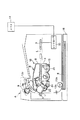
図1は、本発明に係る画像形成装置の一実施例の概略断面を示す。本実施例の画像形成装置Aは、画像情報に応じて電子写真方式にて記録媒体6、例えば記録用紙、OHPシート等に画像を形成するレーザービームプリンタとされる。又、本実施例の画像形成装置Aは、詳しくは後述するように、プロセスカートリッジBが着脱可能とされている。
Example 1
FIG. 1 shows a schematic cross section of an embodiment of an image forming apparatus according to the present invention. The image forming apparatus A of the present embodiment is a laser beam printer that forms an image on a
画像形成装置Aは、パーソナルコンピュータ等のホスト14に接続されて用いられる。そして、画像形成装置AはプロセスカートリッジBにおいて像担持体としてドラム状の感光体(感光ドラム)1を備えており、感光ドラム1の外周には、画像形成手段が配置されている。そして、感光ドラム1の回転過程によって、それらの画像形成手段によりホスト14からの情報に基づいた感光ドラム1周面に現像剤像(トナー像)が形成される。
The image forming apparatus A is used by being connected to a host 14 such as a personal computer. The image forming apparatus A includes a drum-shaped photosensitive member (photosensitive drum) 1 as an image carrier in the process cartridge B, and an image forming unit is disposed on the outer periphery of the
この画像形成工程の帯電工程において、感光ドラム1は、その周囲の画像形成手段のひとつである帯電手段、ここでは感光ドラム1に加圧当接されたローラ状の帯電部材、即ち、DC接触帯電ローラ(帯電ローラ)2によって一様に帯電される。帯電ローラ2には帯電バイアスとして所定の値に固定された直流電圧が印加され、感光ドラム1の表面を負に一様に帯電させる。帯電ローラ2は、感光ドラム1の回転により従動回転する。帯電ローラ2は、感光ドラム1の長手方向(記録媒体6の搬送方向に直交する方向)略全域に亙って当接されている。
In the charging process of the image forming process, the
引き続いて、画像形成装置A内のコントローラ部33において、ホスト14からのプリント要求信号並びに画像データを処理し、露光手段であるスキャナ3を制御することで、感光ドラム1上に静電潜像を形成する。即ち、一様に帯電された感光ドラム1は、露光手段であるスキャナ3からのレーザ光Lにより露光され、その表面に静電潜像が形成される(露光工程)。スキャナ3は、不図示のレーザー光源、ポリゴンミラー、レンズ系等を有し、コントローラ部33の制御により、感光ドラム1上を走査露光することができる。
Subsequently, the
その後、この静電潜像は、現像装置4によって現像剤が供給されて、トナー像として可視化される(現像工程)。ここで、本画像形成装置Aは、一成分現像方式を採用し、現像装置4は、一成分現像剤として負帯電性の非磁性トナー(トナー)22を収容する現像容器21を有する。本実施例では、トナー22には、高速印刷時において、定着特性の優れた粘弾性の低い、体積平均粒径約6μmの略球形トナーを用いた。詳細については後述する。
Thereafter, the electrostatic latent image is visualized as a toner image by supplying a developer by the developing device 4 (developing process). Here, the image forming apparatus A employs a one-component developing method, and the developing device 4 includes a developing
そして、感光ドラム1と対向する現像容器21の一部は、感光ドラム1の長手方向略全域に亙り開口しており、この開口部にローラ状の現像剤担持体(現像手段)である現像ローラ23が配置されている。現像ローラ23は、現像装置4の図中左上方に位置する感光ドラム1に所定の侵入量となるように押圧、接触され、感光ドラム1と順方向に回転駆動される。
A part of the developing
現像ローラ23の図中右下方には、現像ローラ23へのトナーを供給し、又、未現像トナーを現像ローラ23から剥ぎ取る手段として、弾性を有する供給ローラ24が当接されている。供給ローラ24は、回転可能に現像容器21に支持されている。又、供給ローラ24は、現像ローラ23へのトナー供給及び未現像トナーの剥ぎ取り性の点からゴムスポンジローラとし、現像ローラ23と同一方向に回転駆動する。
An
又、現像装置4は、現像ローラ23に担持させるトナー量を規制する現像剤規制部材として、現像ブレード25を備えている。現像ブレード25は、弾性を有するリン青銅製の金属薄板で構成され、自由端側の先端近傍を現像ローラ23の外周面に面接触にて当接するように設けられている。供給ローラ24との摺擦により現像ローラ23上に担持されたトナーは、現像ブレード25との当接部を通過する際に摩擦帯電により電荷付与され、且つ、薄層に規制される。
The developing device 4 includes a developing
このような構成の一成分現像方式を採用する現像装置4において、現像ローラ23には、現像バイアスとして所定の値に固定された直流電圧が印加される。これによって、本実施例では、一様に帯電された感光ドラム1の表面の、負電荷が減衰した露光部を反転現像により現像し、現像剤像(トナー像)とする。
In the developing device 4 that employs the one-component developing system having such a configuration, a DC voltage fixed to a predetermined value as a developing bias is applied to the developing
こうして感光ドラム1上にトナー像が形成される一方、記録媒体6は記録媒体収容部16から供給ローラ12aにより分離給送され、レジストローラ12bで一旦停止する。レジストローラ12bは、記録媒体6の記録位置と感光ドラム1へのトナー像の形成タイミングとの同期をとり、転写手段である転写ローラ5と感光ドラム1との対向部(転写部)へと、記録媒体6を送り出す。こうして、可視化された感光ドラム1上のトナー像は、転写ローラ5の作用によって記録媒体6に転写される(転写工程)。
In this way, a toner image is formed on the
トナー像を転写された記録媒体6は、定着装置9に搬送される。定着装置9で、記録媒体6上の未定着のトナー像は、熱、圧力によって記録媒体6に永久定着される(定着工程)。
The
ここで、定着装置9は、従来例にて説明したフィルム加熱定着装置であり、ヒータ9aによって加熱し、その周囲のフィルム9bと加圧ローラ9cとの間に挟持搬送される記録媒体6上に画像を定着させる。
Here, the fixing
その後、記録媒体6は排出ローラ12cにより機外に排紙される(画像形成工程1回分終了)。
Thereafter, the
又、転写されずに感光ドラム1上に残留した転写残トナーは、クリーニング手段(クリーナ)10によって清掃する。つまり、クリーナ10は、クリーニング部材であるクリーニングブレード7により転写残トナーを感光ドラム1から掻き取り、廃トナー容器8に収納する。クリーニングされた感光ドラム1は画像形成に供される。
Further, untransferred toner remaining on the
ところで、本実施例では、画像形成装置Aは、電子写真感光体である感光ドラム1である像担持体と、この像担持体に作用する画像形成手段(帯電ローラ2、現像装置4、クリーナ10)とを一体的にカートリッジ化し、このカートリッジBを装置本体Aに対して着脱可能とするプロセスカートリッジ方式とされている。
By the way, in this embodiment, the image forming apparatus A includes an image carrier that is a
ここで、画像形成手段としては、電子写真感光体(感光ドラム1)を帯電する帯電手段(帯電ローラ2)、電子写真感光体に現像剤(トナー)を供給する現像手段(現像装置4)、電子写真感光体をクリーニングするクリーニング手段(クリーナ10)が含まれる。つまり、プロセスカートリッジBとは、帯電手段、現像手段及びクリーニング手段と、電子写真感光体とを一体的にカートリッジ化し、このカートリッジを電子写真画像形成装置本体に着脱可能とするか、或いは、帯電手段、現像手段、クリーニング手段のうち少なくとも1つと、電子写真感光体とを一体的にカートリッジ化して電子写真画像形成装置本体に対して着脱可能とするものであるか、或いは、少なくとも現像手段と電子写真感光体とを一体的にカートリッジ化して、このカートリッジを電子写真画像形成装置本体に対して着脱可能としたものである。 Here, as the image forming means, a charging means (charging roller 2) for charging the electrophotographic photosensitive member (photosensitive drum 1), a developing means (developing device 4) for supplying a developer (toner) to the electrophotographic photosensitive member, A cleaning means (cleaner 10) for cleaning the electrophotographic photosensitive member is included. In other words, the process cartridge B is a charging unit, a developing unit, a cleaning unit, and an electrophotographic photosensitive member which are integrated into a cartridge, and the cartridge can be attached to and detached from the main body of the electrophotographic image forming apparatus. In addition, at least one of the developing unit and the cleaning unit and the electrophotographic photosensitive member are integrally formed into a cartridge so as to be detachable from the main body of the electrophotographic image forming apparatus, or at least the developing unit and the electrophotographic unit The photosensitive member is integrally formed into a cartridge, and the cartridge can be attached to and detached from the main body of the electrophotographic image forming apparatus.
本実施例においては、感光ドラム1、帯電ローラ2、現像装置4、クリーナ10が一体的にカートリッジ化され、プロセスカートリッジBを形成し、装置本体Aに着脱可能とされている。プロセスカートリッジBは、装置本体Aが備えた装着手段15を介して、取り外し可能に装置本体Aに装着される。
In this embodiment, the
ここで、本発明の内容の詳細な説明を行う。 Here, the contents of the present invention will be described in detail.
本発明の課題として、高速印刷時においても、現像特性、定着特性を優れたものとするため、本実施例では、現像剤であるトナー22及び現像剤担持体である現像ローラ23を改良した。
As an object of the present invention, in this embodiment, the
トナー22については、以下(1)〜(4)の特性を有する非磁性トナー、即ち前記したように高速印刷時において、定着特性の優れた粘弾性の低い、体積平均粒径約6μmの略球形トナーを用いた。尚、トナーは、結着樹脂と着色剤を少なくとも含む現像剤を意味する。
The
(1)まず、体積平均粒径を4〜10μmとする。なぜなら、体積平均粒径が4μm未満である場合には、トナー粒子の過剰帯電(チャージアップ)が発生しやすいトナーとなり、ネガゴーストが発生してしまい、好ましくない。又、体積平均粒径が10μmを超える場合には、高精細性に劣る画像となり、好ましくないからである。 (1) First, the volume average particle size is 4 to 10 μm. This is because if the volume average particle size is less than 4 μm, the toner particles are likely to be overcharged (charged up) and negative ghosts are generated. On the other hand, if the volume average particle size exceeds 10 μm, the image is inferior in high definition, which is not preferable.
ここで、トナーの体積平均粒径は例えば、下記の測定方法で測定される。 Here, the volume average particle diameter of the toner is measured by, for example, the following measuring method.
測定方法としては、コールターカウンターTA−II型(コールター社製)を用い、個数平均分布を出力するインターフェース(日科機製)及びCX−Iパーソナルコンピュータ(キヤノン製)を接続し、電解液は1級塩化ナトリウムを用いて1%NaCl水溶液を調整する。測定方法としては、上記電解水溶液100〜150ml中に分散剤として界面活性剤(好ましくはアルキルベンゼンスルホン酸)を0.1〜5ml加え、更に測定試料0.5〜50mgを加える。試料を懸濁した電解液は、超音波分散器で約1〜3分間分散処理を行ない、上記コールターカウンターTA−II型によりアパーチャーとして100μmアパーチャーを用いて2〜40μmの粒子の粒度分布を測定し、体積分布を求める。これら求めた体積分布により、サンプルの体積平均粒径が得られる。 As a measuring method, a Coulter counter TA-II type (manufactured by Coulter Co., Ltd.) is used, and an interface (manufactured by Nikkiki) that outputs a number average distribution and a CX-I personal computer (manufactured by Canon) are connected. Prepare 1% NaCl aqueous solution with sodium chloride. As a measuring method, 0.1 to 5 ml of a surfactant (preferably alkylbenzenesulfonic acid) is added as a dispersant to 100 to 150 ml of the above electrolytic aqueous solution, and 0.5 to 50 mg of a measurement sample is further added. The electrolyte solution in which the sample is suspended is subjected to a dispersion treatment with an ultrasonic disperser for about 1 to 3 minutes, and the particle size distribution of particles of 2 to 40 μm is measured using the 100 μm aperture as an aperture by the Coulter Counter TA-II type. Find the volume distribution. The volume average particle diameter of the sample is obtained from the obtained volume distribution.
(2)形状係数SF1が100以上130未満、より好ましくは100以上125未満であるものとする。なぜなら、トナー粒子が球形に近いほうが、未定着画像においてトナー粒子間の空隙が少なく、トナー粒子全体に均一に熱が伝わり易いのに対して、トナー粒子が歪である場合には、未定着画像におけるトナー粒子間の空隙にばらつきが生じ、トナー粒子への熱の伝わり方が不均一となるため、定着不良が生じるものとなるからである。具体的には、定着画像表面を擦った際にトナー画像の剥離が生じるものとなるからである。 (2) The shape factor SF1 is 100 or more and less than 130, more preferably 100 or more and less than 125. This is because when the toner particles are closer to a sphere, there are fewer voids between the toner particles in the unfixed image, and heat is easily transmitted to the entire toner particles, whereas when the toner particles are distorted, the unfixed image This is because the gaps between the toner particles in the toner vary and the heat transfer to the toner particles becomes non-uniform, resulting in poor fixing. Specifically, the toner image is peeled off when the surface of the fixed image is rubbed.
尚、本発明に用いられる形状係数を示すSF1とは、日立製作所製FE−SEM(S−800)を用い、倍率500倍に拡大したトナー像を100個無作為にサンプリングし、その画像情報はインターフェースを介してニコレ社製画像解析装置(Luzex3)に導入し、解析を行い、数式(8)より算出し得られた値を形状係数SF1と定義した。 In addition, SF1 which shows the shape factor used for this invention uses Hitachi FE-SEM (S-800), and randomly sampled 100 toner images magnified 500 times, and the image information is The image was introduced into the image analysis apparatus (Luxex 3) manufactured by Nicole via the interface, analyzed, and the value obtained from Equation (8) was defined as the shape factor SF1.
(3)140℃における貯蔵弾性率G’(140℃)を2.0×10³dN/m2以上
2.0×10⁴dN/m2未満、好ましくは2.0×103dN/m2以上1.0×104dN/m2未満とする。そうすることによって、トナーの結着バインダー部における熱的特性を好ましいものとすることが出来る。
(3) Storage elastic modulus G ′ (140 ° C.) at 140 ° C. of 2.0 × 10 3 dN / m 2 or more and less than 2.0 × 10 4 dN / m 2 , preferably 2.0 × 10 3 dN / m 2 or more and less than 1.0 × 10 4 dN / m 2 . By doing so, the thermal characteristics in the binder binder portion of the toner can be made favorable.
(4)フローテスタ昇温法によるトナーの粘度が1.0×10³Pa・sとなるときの測定温度を115℃以上130℃未満、より好ましくは115℃以上125℃未満とする。そうすることによって、離型剤や着色剤の影響も加味したトナー全体としての熱的特性を好ましいものとすることが出来る。 (4) The measurement temperature when the viscosity of the toner by the flow tester temperature rising method is 1.0 × 10 3 Pa · s is 115 ° C. or higher and lower than 130 ° C., more preferably 115 ° C. or higher and lower than 125 ° C. By doing so, it is possible to make preferable the thermal characteristics of the whole toner in consideration of the influence of the release agent and the colorant.
(5)メタノール/水混合溶媒に対する濡れ性を780nmの波長光の透過率で測定した場合、透過率が50%のときのメタノール濃度が30〜60体積%の範囲内であるものとする。なぜなら、透過率が50%のときのメタノール濃度が30体積%未満である場合には、トナー粒子表層に親水性物質が多く存在する濡れ易いトナーであり、空気中の水分の影響を受けやすいため、画像光沢均一性に劣るトナーとなるからである。一方、透過率が50%のときのメタノール濃度が60体積%を超える場合には、濡れ難いトナーとなって画像光沢均一性には優れるものの、表面ワックス量が過多である場合には保存性に劣り、外添剤として用いた微粒子が適切な量及び適切な材料ではない場合には、定着画像均一性に劣るトナーとなる。 (5) When the wettability with respect to the methanol / water mixed solvent is measured by the transmittance of light having a wavelength of 780 nm, the methanol concentration when the transmittance is 50% is within the range of 30 to 60% by volume. This is because when the methanol concentration is less than 30% by volume when the transmittance is 50%, the toner particle surface layer has a large amount of a hydrophilic substance and is easily wetted, and is easily affected by moisture in the air. This is because the toner is inferior in image gloss uniformity. On the other hand, when the methanol concentration exceeds 50% by volume when the transmittance is 50%, the toner becomes difficult to wet and has excellent image gloss uniformity, but when the surface wax amount is excessive, the storage stability is improved. If the fine particles used as the external additive are not in an appropriate amount and an appropriate material, the toner is inferior in fixed image uniformity.
(6)結着樹脂の主たる成分をスチレン−アクリル化合物とする。なぜなら、長期に渡る使用においても現像特性の変化が小さく、耐久性に優れたトナーを得ることができる。 (6) The main component of the binder resin is a styrene-acrylic compound. This is because a change in development characteristics is small even in long-term use, and a toner having excellent durability can be obtained.
ここで、この(1)〜(6)の性質を有する本実施例のトナー22について、定着性と2万枚画像形成による耐久性(カブリ)の比較結果を表1に示す。
Here, with respect to the
本実施例のトナー22としては、それぞれの物性値が、上記の(1)〜(6)の範囲内にある、トナー22a、22bを用いた。
As the
比較例としては、上記の(1)の体積平均粒径が4〜10μmとする性質、且つ(6)の決着樹脂がスチレンーアクリル化合物を含む条件を満たし、(2)、(3)、(4)、(5)の値をそれぞれ変更した、トナー22c、22d、22e、22f、22gの5種類を用いた。 As a comparative example, the above (1) has a property that the volume average particle diameter is 4 to 10 μm, and the final resin of (6) satisfies the condition containing a styrene-acryl compound, and (2), (3), ( 4) and 5 types of toners 22c, 22d, 22e, 22f, and 22g, in which the values of (5) were changed, were used.
ここで、画像形成は常温常湿(25℃/60%)環境下で行い、現像ローラ23の表面粗さはRa=0.8μm、Rz=8μm、Sm=200μmのものを使用した。
Here, image formation was performed in an environment of normal temperature and humidity (25 ° C./60%), and the developing
本実施例でのカブリとは、トナーを充分摩擦帯電できずにベタ白地にトナーを現像してしまう問題であり、○は紙上付着無し、△は少し目立つ程度、×は非常に目立つ程度のものである。 Fogging in this embodiment is a problem that the toner cannot be sufficiently triboelectrically charged and develops the toner on a solid white background. ○ is no adhesion on paper, Δ is a little noticeable, × is a very noticeable It is.
本実施例のトナーはトナー22a、22b、及び(5)の濡れ性のみ条件外のトナー22c、22dについて、オフセット、画像の光沢、均一性等の定着性については、(2)〜(4)の物性値を上記の範囲外としたトナー22e、22f、22gと比べて、良好となった。つまり、本発明の課題における定着性に関しては、物性値の条件としては、上記の(1)粒径、(2)形状係数、(3)貯蔵弾性率、(4)粘度の物性値の条件を満たすことによって、改善可能であり、更に均一性を施すために、(5)の濡れ性の条件を上記のようにする。 In the toner of this embodiment, toners 22a and 22b, and toners 22c and 22d that are out of the wettability conditions of (5), the fixing properties such as offset, image gloss, and uniformity are (2) to (4). As compared with the toners 22e, 22f, and 22g, the physical property values of which were out of the above range were improved. That is, regarding the fixability in the subject of the present invention, the physical property value conditions are the above (1) particle size, (2) shape factor, (3) storage elastic modulus, and (4) viscosity physical property values. By satisfying the above, the wettability condition of (5) is set as described above in order to improve the uniformity and to provide further uniformity.
ここで、定着性が良好であったトナー22a〜22dにおいて、カブリに関しては、トナー140℃における貯蔵弾性率G’(140℃)(dN/m2)が高いほど悪い結果となっている。この実験でのカブリは、現像ローラ23表面へのトナー融着による摩擦帯電性低下であり、柔らかいトナーの方が現像ブレード25との摺擦により融着しやすいことが原因である。
Here, in the toners 22a to 22d having good fixability, the higher the storage elastic modulus G ′ (140 ° C.) (dN / m 2 ) at the toner 140 ° C., the worse the fog. Fogging in this experiment is a decrease in frictional chargeability due to toner fusion to the surface of the developing
又、現像ローラ23については、本実施例では、表面粗さ、抵抗値、硬度等の物性の操作が容易であるため、芯金上に少なくとも弾性層および薄層の表面層を設けた弾性ローラを現像ローラ23に用いている。つまり、弾性層として、シリコンゴムを基層とし、ウレタン粒子を含むウレタン樹脂を表層にコートした現像ローラを用いた。そして、この現像ローラ23の表面粗さについて考慮する。
Further, with respect to the developing
ここで、この現像ローラ23の表面粗さは、「JIS B 0601(1994)」に基づき、Ra(中心線平均粗さ)、Rz(十点平均粗さ)とSm(凹凸の平均間隔)により示している。具体的には、粗さ曲線からその中心線の方向に測定長さaとして2.5mmの部分を抜き取り、この抜き取り部分の中心線をX軸、縦倍率の方向をY軸、粗さ曲線をy=f(x)で表したとき、数式(9)によって求められる値をマイクロメートル(μm)で表したものを言う。
Here, the surface roughness of the developing
ここで、RzとSmの計算法は、図2に示す、表面粗さ測定器のデータより数式(10)、数式(11)を用いて計算する。表面粗さ測定器には小阪研究所社製「サーフコーダーSE−3400」を用いた。 Here, the calculation method of Rz and Sm is calculated using Formula (10) and Formula (11) from the data of the surface roughness measuring device shown in FIG. As the surface roughness measuring instrument, “Surf Coder SE-3400” manufactured by Kosaka Laboratory Ltd. was used.
Rzは、図2(a)にしめす表面粗さ測定器による、表面の高さの中間値Xからとの差を、(a)より大きい部分で5個、小さい部分で5個と、合計10個とり、その値n1〜n5、n’1〜n’5から数式(10)で求める。 Rz is a total of 10 differences from the intermediate value X of the surface height measured by the surface roughness measuring device shown in FIG. Individually obtained from the values n1 to n5 and n′1 to n′5 by the formula (10).
Smは、図2(b)に示すデータにおいて、表面が凸凹の最大値と最小値との間を一回上下する距離を一山として、測定した表面距離Lにおける凸凹の山の数nを用いて、数式(11)で求める。 Sm uses the number n of uneven peaks in the measured surface distance L, where the distance that the surface moves up and down once between the maximum and minimum values of the unevenness in the data shown in FIG. Then, it is obtained by Expression (11).
次に、表1に示した結果で、上記(1)〜(6)の現像剤の条件を満たしたトナーであり、定着性は良好であるが、2万枚画像形成後にかぶりが発生するトナー22bを用いた画像形成時の現像ローラ23表面粗さの影響を説明する。
Next, as a result of the results shown in Table 1, the toner satisfies the developer conditions (1) to (6) described above and has good fixability, but the toner generates fog after forming 20,000 sheets of images. The influence of the surface roughness of the developing
現像ローラ23はAsker−C硬度で50°MD−1硬度で40°のものを用いた。
The developing
画像形成装置Aにおいて、常温常湿(25℃/60%)環境下、2万枚の画像形成を行ったところ、現像ローラ23の表面粗さと初期画像濃度と耐久性(カブリ)に、表2に示すような関係がある。
In the image forming apparatus A, 20,000 sheets of images were formed in a room temperature and normal humidity (25 ° C./60%) environment. Table 2 shows the surface roughness, initial image density, and durability (fogging) of the developing
ここで、M/Sは現像領域に搬送される単位面積当たりの現像剤の量であり、単位はmg/cm2である。融着は現像ローラ表面へのトナー融着を表しており、○は融着無し、×は融着有りである。 Here, M / S is the amount of developer per unit area conveyed to the development region, and the unit is mg / cm 2 . Fusing represents toner fusing on the surface of the developing roller, ◯ indicates no fusing, and X indicates fusing.
表2の関係から初期濃度は現像ローラ23上のM/Sにより決まっており、M/Sは表面粗さRaに比例していることが分かる。本実施例では、初期濃度に関しては表面粗さRa≧0.8μmで良好である。
From the relationship in Table 2, it can be seen that the initial density is determined by the M / S on the developing
本実施例でのカブリとは、トナーを充分摩擦帯電できずにベタ白地にトナーを現像してしまう問題を表しており、本実施例では2つの要因が考えられる。 The fog in this embodiment represents a problem that the toner cannot be sufficiently frictionally charged and develops the toner on a solid white background. In this embodiment, two factors can be considered.
要因1:耐久後現像ローラ23表面へのトナー融着による摩擦帯電性低下。
Factor 1: A decrease in frictional charging property due to toner fusion to the surface of the developing
要因2:耐久後摩擦帯電性が低下している劣化トナーに対して、表面粗さRaが大きくM/Sが大きいため充分摩擦帯電できない。 Factor 2: Since the surface roughness Ra is large and M / S is large with respect to the deteriorated toner whose friction chargeability is lowered after durability, the toner cannot be sufficiently frictionally charged.
本実施例では、カブリに関しては、Rz/Sm≧0.06であれば要因1のカブリを防ぐことができる。
In the present embodiment, with respect to the fog, if Rz / Sm ≧ 0.06, the fog of the
要因2によるカブリを防ぐためには、Ra≦2.0(μm)とすれば良い。本実施例では、構成No.2、構成No.6のように現像ローラ23表面へトナー融着していても、表面粗さRaが低ければカブリが発生しないことが確認された。
In order to prevent fogging due to
又、表面粗さRaを大きくするためRz/Smを大きくしていくと、構成No.16のように表層剥れが発生した。これは表層粗し粒子の粒径が大きく且つ部数が多すぎるため、表層ウレタン樹脂の結着力が低下したことが原因であると考えられる。このためRz/Sm≦0.4でなければならない。 Further, when Rz / Sm is increased to increase the surface roughness Ra, the structure No. As shown in FIG. This is considered to be caused by a decrease in the binding force of the surface urethane resin because the surface roughening particles have a large particle size and have too many parts. Therefore, Rz / Sm ≦ 0.4 must be satisfied.
以上の結果から本実施例における現像ローラ23の表面粗さは、0.06≦Rz/Sm≦0.4、0.8≦Ra≦2.0(μm)が最適であり、現像ローラ23上のM/Sは、0.25≦M/S≦0.5が最適である。表2からも、この表面粗さで、かぶりは発生しないことが明らかである。
From the above results, the optimum surface roughness of the developing
以上、本実施例によれば、現像ローラの表面粗さを最適にすることにより、高速印刷時においても、高い定着性能を維持し、現像剤担持体表面へのトナー融着による画像不良を防止できる画像形成装置を提供することができる。 As described above, according to this embodiment, by optimizing the surface roughness of the developing roller, high fixing performance is maintained even during high-speed printing, and image defects due to toner fusion to the surface of the developer carrier are prevented. An image forming apparatus that can be used can be provided.
従って、本発明では、一成分現像方式にて使用される、結着樹脂と着色剤を少なくとも有する非磁性トナーである現像剤及び現像剤担持体となる現像ローラの表面粗さを調整するものであり、トナーが、(1)体積平均粒径が4〜10μmであり、(2)形状係数SF1が100以上130未満であり、(3)140℃における貯蔵弾性率G’(140℃)が、2.0×10³dN/m2以上2.0×104dN/m2未満であり、(4)フローテスタ昇温法によるトナーの粘度が、1.0×103Pa・sとなるときの測定温度が115℃以上130℃未満であるといった物性値を満たし、且つ、現像ローラは、弾性を有し、その表面粗さRa(中心線平均粗さ)、Rz(十点平均粗さ)とSm(凹凸の平均間隔)が数式(12)の関係を有している現像装置、そしてそれを備えたプロセスカートリッジ、及び画像形成装置を提供し、フィルム加熱定着装置等を使用した、高速化を進めた画像形成装置においても、定着不良や、かぶり等を防止できるようになった。 Therefore, the present invention adjusts the surface roughness of the developer used as a developer and developer carrier, which is a non-magnetic toner having at least a binder resin and a colorant, used in the one-component development system. Yes, the toner has (1) a volume average particle diameter of 4 to 10 μm, (2) a shape factor SF1 of 100 or more and less than 130, and (3) a storage elastic modulus G ′ (140 ° C.) at 140 ° C. 2.0 × 10 3 dN / m 2 or more and less than 2.0 × 10 4 dN / m 2 , and (4) the viscosity of the toner by the flow tester heating method is 1.0 × 10 3 Pa · s. The measured temperature satisfies the physical property value of 115 ° C. or higher and lower than 130 ° C., and the developing roller has elasticity, and its surface roughness Ra (center line average roughness), Rz (ten-point average roughness) ) And Sm (average interval of irregularities) have the relationship of Equation (12) Development device, process cartridge including the same, and image forming apparatus are provided, and even in an image forming apparatus using a film heating and fixing apparatus and the like that has been accelerated, fixing defects and fogging can be prevented. Became.
又、本発明は、画像形成装置がプロセスカートリッジ方式とされていない場合にも適用することができ、本実施例と同様の効果を奏し得る。 The present invention can also be applied to a case where the image forming apparatus is not of a process cartridge type, and can achieve the same effects as the present embodiment.
実施例2
本実施例では、実施例1と同構成の画像形成装置において、表1でのトナー22bを用いた画像形成時の現像ローラ23硬度の影響を説明する。ここでは、実施例1に説明した条件を満たす、表面粗さRa=1.2μm、Rz=10μm、Sm=100μmの現像ローラ23を用いた。
Example 2
In the present embodiment, the influence of the hardness of the developing
表3は、画像形成装置Aにおいて、常温常湿(25℃/60%)環境下、2万枚の画像形成を行った後の、現像ローラ23の硬度と、画像のかぶり、ローラ23の表層剥がれ及び画像に現れる現像スジと、の関係である。現像スジとは、現像ローラ23と現像ブレード25との摺擦により現像ブレード23にトナーが融着することが原因である。
Table 3 shows the hardness of the developing
この結果は、現像ローラ23の全体硬度としてのAsker−C硬度が低いと、劣化トナーを充分摩擦帯電できずにカブリが悪化することを示している。
This result indicates that when the Asker-C hardness as the overall hardness of the developing
又、表面の硬度を測定しているMD−1硬度が高いと、現像ブレード25との摺擦時トナーへの圧を大きくし、現像スジを悪化させていることが分かる。
It can also be seen that if the MD-1 hardness, which measures the surface hardness, is high, the pressure applied to the toner during rubbing against the developing
この結果から、本実施例では、Asker−C硬度で40°〜60°、MD−1硬度で25°〜50°の範囲現像ローラ23を使用することにした。このことによって、画像のかぶり、現像スジ、そしてローラ23の表層剥がれを防止できる。
From this result, in this embodiment, it was decided to use the developing
尚、ここでは、Asker−C硬度の測定には、日本ゴム協会標準規格SRIS0101に準拠したAsker−C型スプリング式ゴム硬度計(高分子計器(株)社製)を用い、MD−1硬度の測定には、MICRO DUROMETER MD−1型(高分子計器(株)社製)を用いた。 Here, the Asker-C hardness is measured by using an Asker-C spring type rubber hardness meter (manufactured by Kobunshi Keiki Co., Ltd.) in accordance with the Japan Rubber Association standard SRIS0101. For the measurement, MICRO DUROMETER MD-1 type (manufactured by Kobunshi Keiki Co., Ltd.) was used.
実施例3
本実施例では、実施例1の同様の構成の画像形成装置において、更に、現像装置4における良好な現像設定を考慮する。
Example 3
In the present embodiment, in the image forming apparatus having the same configuration as that of the first embodiment, further favorable development settings in the developing device 4 are taken into consideration.
図1における現像装置は、実施例1にても説明したように、現像ブレード25と現像ローラ23の摺擦によりトナー22に電化を与える一成分現像方式が実施するものである。よって、現像ブレード25と現像ローラ23との配置関係は重要であり、ここでは、ブレード25の現像ローラ23に対する当接圧Pに着目した。
As described in the first embodiment, the developing device in FIG. 1 implements a one-component developing system that electrifies the
球形化処理を受けた非磁性トナーは、球形であるがゆえ現像ブレード25によるコート量の規制がしづらい。満足いく画質を実現するためには、現像ブレード25による規制力を高めることが必要である。
Since the non-magnetic toner that has undergone the spheroidizing process is spherical, it is difficult to regulate the coating amount by the developing
ブレード25の当接圧P、即ち現像ローラ23長手方向についての1cmあたりの線圧(g/cm)と、図3に示す、現像ブレード25が現像ローラ23に当接する当接ニップNの最下流の位置である当接最下流位置からブレード25自由端までの距離であるNEをそれぞれ組み合わせて画像形成動作をおこなった。尚、現像ブレード25は、現像ローラ23に対して下流側から当接しているので、当接最下流位置とは、現像ローラ23の回転方向では上流側である。
The contact pressure P of the
図4にこの結果を示す。この評価結果より、NEの範囲としては、0.5≦NE≦2.0が良いことがわかった。NEが0.5mm未満だとエッジ当接になる場合があり、コート量が少なくなって濃度薄や画像白抜けになった。又、2.0mmを超えるとトナーコート量が大きくトナー層形成が不安定となった。 FIG. 4 shows the result. From this evaluation result, it was found that 0.5 ≦ NE ≦ 2.0 is good as the NE range. When NE is less than 0.5 mm, edge contact may occur, and the amount of coating decreases, resulting in low density and white spots in the image. On the other hand, when the thickness exceeds 2.0 mm, the toner coating amount is large and the toner layer formation becomes unstable.
又、当接圧Pは25≦P≦54が良いことがわかった。Pが25g/cm未満の場合は、トナーの帯電量が不十分で画質の悪化や濃度薄が生じた。逆に50g/cmを超えると、トナーコート量が少なくなり耐久でラインが散り散りとなった。 It was also found that the contact pressure P should be 25 ≦ P ≦ 54. When P was less than 25 g / cm, the charge amount of the toner was insufficient and the image quality deteriorated and the density decreased. On the other hand, when it exceeded 50 g / cm, the toner coat amount was decreased, and the lines were scattered for durability.
更にPとNEには次のような関係があることがわかった。 Furthermore, it was found that P and NE have the following relationship.
即ち、Pが小さい場合はトナー規制力が小さいのでNEを短くしないとコート量が大きくなり画像が悪化する。Pが大きくなるに連れてトナーの規制力が大きくなるため、NEを大きくしたほうがトナーコートが安定し画質が良化する。 That is, when P is small, the toner regulating force is small, and unless NE is shortened, the coating amount increases and the image deteriorates. As P increases, the toner's regulatory power increases, so increasing NE increases the stability of the toner coat and improves image quality.
図4に示す実験結果は数式(13)で表すことができる。これは、図4に示すNEとPの関係において、その上限を示すグラフaと下限を示すグラフbとの間の領域であるXを規定したものである。 The experimental result shown in FIG. 4 can be expressed by Equation (13). This defines X, which is a region between the graph a indicating the upper limit and the graph b indicating the lower limit in the relationship between NE and P shown in FIG.
従って、0.5≦NE≦2.0、且つ25≦P≦54、更に6.0×NE+22≦P≦6.0×NE+42の範囲に、現像ブレード25を当接させることで、球形化処理されたトナーを用いて安定したトナー層を形成でき、画質を満足できた。
Accordingly, the developing
そこで本実施例では、現像ブレード25を、現像ローラ23に対して当接圧P(現像ローラ長手方向についての1cmあたりの線圧(g/cm))を40g/cmで当接するように現像装置4に設置している。
Therefore, in this embodiment, the developing
又、現像ローラ23とブレード25の当接巾であるニップNは1.5mm、当接最上流位置(スリーブ回転方向の上流)からブレード自由端までの距離であるNEは1.0mmとしている。
The nip N, which is the contact width between the developing
このようにすることで、現像ローラ23にトナー22を良好にコートできるようになり、白抜けや、濃度低下、濃度ムラ、ラインズレ等の画像不良を防止できた。
By doing so, the
実施例4
本実施例では、実施例1の同様の構成の画像形成装置において、更に、現像ローラ23の表面粗さについて、考慮する。
Example 4
In this embodiment, the surface roughness of the developing
実施例1に示す表2において、同じRaの場合、Rz/Smが大きい方が現像ローラ23表面にトナー融着しにくい理由を説明する。
In Table 2 shown in Example 1, in the case of the same Ra, the reason why the larger Rz / Sm is, the more difficult to fuse the toner to the surface of the developing
図5にRa、Rzが一定でSmのみが違う簡単な現像ローラ23表面の粗さプロフィール図5(a)と図5(b)を示す。この図5(a)(b)に示すように、Rz/Smは粗さプロフィールの傾きの絶対値を示し、Smが小さい時、つまり、Rz/Smが大きい時の図5(a)に示すデータは、Smが小さい時、つまりRz/Smが大きい時のデータである図5(b)のデータよりも、傾きが大きい。よって、Rz/Smが大きくなる程傾きが大きくなることが分かる。
FIG. 5 shows a simple roughness profile of the surface of the developing
次に、図6に現像ローラ23の表面粗さRz=12μmの凹部に粒径6μmトナー22を担持した様子を示す。このように、凹部上のトナー22は凹部にて最も窪んだ部分t1に到達しない状況で考えると、凹部にて最も窪んだ部分t1とトナー22表面との間には隙間uを有するが、Rz/Smが大きい方が、凹部にて最も窪んだ部分t1とトナー22表面との距離である隙間高さUが大きいことが分かる。更に、表2で示した本実施例で使用した現像ローラ23の表面粗さに対する、粒径6μmのトナーにおいて、隙間高さUの関係を表4に示す。
Next, FIG. 6 shows a state in which the
尚、表4における隙間高さUの対粒径割合(%)Qは数式(14)により算出した。 In Table 4, the ratio (%) Q to the particle size of the gap height U was calculated by Equation (14).
この表4において、隙間高さUの対粒径割合が小さい(0.7以下)ものが、現像ローラ23表面へトナー融着するという結果を示している。即ち、現像ブレード25と現像ローラ23との摺擦の際に、現像ローラ23の表面とトナーの間に隙間がある方が、現像ローラ23表面とトナーの摩擦が小さいため融着しにくいと考えられる。表2と表3の結果から、0.7≦Q≦28であることが好ましいことが明らかとなった。
Table 4 shows the result that toner having a small ratio (0.7 or less) with respect to the particle size of the gap height U is fused to the surface of the developing
実施例5
次に、本発明に係る画像形成装置の他の実施例について説明する。
Example 5
Next, another embodiment of the image forming apparatus according to the present invention will be described.
実施例1にて説明した画像形成装置Aにおいて、現像手段として感光ドラム1に対し現像ローラ23は、所定の侵入量となるように押圧、接触され、現像される方法を用いたが、本実施例においては図7に示すように、現像剤担持体23を像担持体1と非接触に保ちながら、像担持体1上の潜像の現像を行うジャンピング現像を用いたものである。
In the image forming apparatus A described in the first embodiment, a method is used in which the developing
従って、実施例1にて説明した全ての現像装置4構成部が同様に本実施例のプロセスカートリッジBにおいても適用される。従って、これら構成および作用についての説明は、実施例1において行った上記説明を援用する。 Accordingly, all the developing device 4 components described in the first embodiment are similarly applied to the process cartridge B of the present embodiment. Therefore, the above description made in Example 1 is used for the description of these configurations and operations.
実施例1にて説明した画像形成装置Aにおいて、画像形成装置Aが図8のように、プロセスカートリッジBを複数有し、それらを縦型に配したインラインフルカラーレーザービームプリンタである場合、本実施例において実施例1〜4に説明した発明を適用することにより、画像形成枚数増加に伴うトナー劣化時においてもトナーに対する摩擦帯電性が低下せず、カブリ問題が発生しないフルカラー電子写真画像形成装置を提供することができる。この時現像剤の色毎にプロセスカートリッジBを備える。このような方法をとることにより、4色のプロセスカートリッジBに対し、それぞれ独立に実施例1〜4に説明した本発明を実施することで、同様に、高速化に伴う画像不良を防止する効果を得ることが出来る。プロセスカートリッジの数は4つに限らない。
In the image forming apparatus A described in the first embodiment, when the image forming apparatus A is an inline full-color laser beam printer having a plurality of process cartridges B arranged vertically as shown in FIG. By applying the invention described in
本実施例では、インラインフルカラーレーザービームプリンタを用いたが、ロータリ方式を用いたフルカラーレーザービームプリンタにおいても同等の効果を得ることができる。もちろん感光ドラムの周囲に固定して複数の現像装置を備えた構成についても、中間転写方式を採用したものでも、現像装置の構成以外は、どのように変化させた構成の画像形成装置においても適用できる。 In this embodiment, the inline full color laser beam printer is used, but the same effect can be obtained in a full color laser beam printer using a rotary system. Of course, the configuration provided with a plurality of developing devices fixed around the photosensitive drum is also applicable to the image forming apparatus having any configuration other than the configuration of the developing device, even if the intermediate transfer method is adopted. it can.
1 感光ドラム(像担持体)
4 現像装置
22 トナー(現像剤)
23 現像ローラ(現像剤担持体)
25 現像ブレード(現像剤規制部材)
A 画像形成装置
B プロセスカートリッジ
1 Photosensitive drum (image carrier)
4 Developing
23 Development roller (developer carrier)
25 Development blade (developer regulating member)
A Image forming device B Process cartridge
Claims (12)
前記現像剤は、
結着樹脂と着色剤を少なくとも有する非磁性トナーを含み、
体積平均粒径が4〜10μmであり、
形状係数SF1が100以上130未満であり、
140℃における貯蔵弾性率G’(140℃)が、2.0×10³dN/m2以上2.0×104dN/m2未満であり、
フローテスタ昇温法により求めた粘度が、1.0×10³Pa・sとなるときの測定温度が115℃以上130℃未満であり、
前記現像剤担持体は、
弾性層を有し、
その表面粗さRa(中心線平均粗さ)、Rz(十点平均粗さ)とSm(凹凸の平均間隔)が数式(1)の関係を有していることを特徴とする現像装置。
The developer is
Including a non-magnetic toner having at least a binder resin and a colorant;
The volume average particle size is 4-10 μm,
The shape factor SF1 is 100 or more and less than 130,
Storage elastic modulus G ′ (140 ° C.) at 140 ° C. is 2.0 × 10 3 dN / m 2 or more and less than 2.0 × 10 4 dN / m 2 ,
The measurement temperature when the viscosity determined by the flow tester temperature rising method is 1.0 × 10 3 Pa · s is 115 ° C. or more and less than 130 ° C.,
The developer carrier is
Having an elastic layer,
The developing device characterized in that the surface roughness Ra (center line average roughness), Rz (ten-point average roughness) and Sm (average interval of irregularities) have the relationship of the formula (1).
前記貯蔵弾性率G’(140℃)が、2.0×10³dN/m2以上1.0×104dN/m2未満であり、
前記フローテスタ昇温法によって求められる粘度が1.0×10³Pa・sとなるときの測定温度が115℃以上125℃未満であることを特徴とする請求項1記載の現像装置。 The developer is
The storage elastic modulus G ′ (140 ° C.) is 2.0 × 10 3 dN / m 2 or more and less than 1.0 × 10 4 dN / m 2 ,
A developing device according to claim 1, wherein the viscosity is determined by the flow tester heating method is 125 less than ° C. measured temperature is 115 ° C. or more when the 1.0 × 10 3 Pa · s.
メタノール/水混合溶媒に対する濡れ性を780nmの波長光の透過率で測定した場合、透過率が50%のときのメタノール濃度が30〜60体積%の範囲内であることを特徴とする請求項1又は2の現像装置。 The developer is
2. The methanol concentration when the transmittance is 50% when the wettability with respect to a methanol / water mixed solvent is measured by the transmittance of light having a wavelength of 780 nm is within a range of 30 to 60% by volume. Or the developing device of 2.
形状係数SF1が100以上125未満であることを特徴とする請求項1〜3のいずれかの項に記載の現像装置。 The developer is
The developing device according to any one of claims 1 to 3, wherein the shape factor SF1 is 100 or more and less than 125.
前記結着樹脂は、スチレン−アクリル化合物を含むことを特徴とする請求項1〜4のいずれかの項に記載の現像装置。 The developer is
The developing device according to claim 1, wherein the binder resin includes a styrene-acrylic compound.
芯金上に少なくとも前記弾性層及び表面層を設けた弾性ローラで構成されることを特徴とする請求項1〜5のいずれかの項に記載の現像装置。 The developer carrier is
6. The developing device according to claim 1, wherein the developing device includes an elastic roller having at least the elastic layer and a surface layer provided on a cored bar.
表面硬度が、Asker−C硬度で40°〜60°であり、MD−1硬度で、25°〜50°であることを特徴とする請求項1〜6のいずれかの項に記載の現像装置。 The developer carrier is
The developing device according to claim 1, wherein the surface hardness is 40 ° to 60 ° in Asker-C hardness and 25 ° to 50 ° in MD-1 hardness. .
Priority Applications (2)
| Application Number | Priority Date | Filing Date | Title |
|---|---|---|---|
| JP2004097060A JP4497978B2 (en) | 2004-03-29 | 2004-03-29 | Developing device, process cartridge, and image forming apparatus |
| US11/090,282 US7209690B2 (en) | 2004-03-29 | 2005-03-28 | Developing apparatus |
Applications Claiming Priority (1)
| Application Number | Priority Date | Filing Date | Title |
|---|---|---|---|
| JP2004097060A JP4497978B2 (en) | 2004-03-29 | 2004-03-29 | Developing device, process cartridge, and image forming apparatus |
Publications (3)
| Publication Number | Publication Date |
|---|---|
| JP2005283928A JP2005283928A (en) | 2005-10-13 |
| JP2005283928A5 JP2005283928A5 (en) | 2007-05-24 |
| JP4497978B2 true JP4497978B2 (en) | 2010-07-07 |
Family
ID=34989994
Family Applications (1)
| Application Number | Title | Priority Date | Filing Date |
|---|---|---|---|
| JP2004097060A Expired - Fee Related JP4497978B2 (en) | 2004-03-29 | 2004-03-29 | Developing device, process cartridge, and image forming apparatus |
Country Status (2)
| Country | Link |
|---|---|
| US (1) | US7209690B2 (en) |
| JP (1) | JP4497978B2 (en) |
Families Citing this family (14)
| Publication number | Priority date | Publication date | Assignee | Title |
|---|---|---|---|---|
| US20050273795A1 (en) * | 2004-06-03 | 2005-12-08 | Hokushin Corporation | Disc-loading roll |
| US8043081B2 (en) * | 2005-10-17 | 2011-10-25 | Bridgestone Corporation | Mold for forming developer blade, and developer blade formed with same |
| US7650104B2 (en) * | 2006-02-24 | 2010-01-19 | Canon Kabushiki Kaisha | Developing apparatus including developer carrying member and developer regulating member with surface roughness parameters |
| JP2007286541A (en) * | 2006-04-20 | 2007-11-01 | Kyocera Mita Corp | Toner |
| US7727698B2 (en) * | 2006-06-22 | 2010-06-01 | Konica Minolta Business Technologies, Inc. | Image forming method |
| JP2008139552A (en) * | 2006-12-01 | 2008-06-19 | Ricoh Co Ltd | Developer regulating member, developing device, process cartridge, image forming apparatus, and manufacturing method of developer regulating member |
| US7853188B2 (en) * | 2007-01-10 | 2010-12-14 | Kabushiki Kaisha Toshiba | Image forming apparatus and image forming method |
| JP2008180890A (en) * | 2007-01-24 | 2008-08-07 | Ricoh Co Ltd | Developing device, image forming apparatus, image forming method, and process cartridge |
| JP5108346B2 (en) * | 2007-03-20 | 2012-12-26 | 東海ゴム工業株式会社 | Developing roll |
| JP5115015B2 (en) * | 2007-04-20 | 2013-01-09 | 富士ゼロックス株式会社 | Toner cartridge |
| JP2009009035A (en) * | 2007-06-29 | 2009-01-15 | Canon Inc | Developing device and cartridge |
| JP2010008994A (en) * | 2008-05-27 | 2010-01-14 | Canon Inc | Toner supplying roller, developing apparatus, and image forming apparatus |
| JP5721364B2 (en) | 2010-08-19 | 2015-05-20 | キヤノン株式会社 | Image forming apparatus |
| JP2013137500A (en) * | 2011-11-28 | 2013-07-11 | Ricoh Co Ltd | Development device and image forming apparatus |
Citations (4)
| Publication number | Priority date | Publication date | Assignee | Title |
|---|---|---|---|---|
| JPH08328306A (en) * | 1995-05-30 | 1996-12-13 | Canon Inc | Toner and developing method |
| JPH09311499A (en) * | 1996-05-21 | 1997-12-02 | Mitsubishi Chem Corp | One-component developer and image forming method using the same |
| JP2002182465A (en) * | 2000-12-15 | 2002-06-26 | Konica Corp | Image forming method and device, and one-component and two-component developer used therefor |
| JP2002304053A (en) * | 2001-04-03 | 2002-10-18 | Canon Inc | Developing roll and electrophotographic device using it |
Family Cites Families (13)
| Publication number | Priority date | Publication date | Assignee | Title |
|---|---|---|---|---|
| JPH01257982A (en) * | 1988-04-08 | 1989-10-16 | Minolta Camera Co Ltd | Developing device |
| JP3096101B2 (en) | 1991-08-01 | 2000-10-10 | 株式会社リコー | Electrostatic image developing toner, developing machine using the same, electrophotographic image forming apparatus, and electrophotographic image forming method |
| US5307127A (en) * | 1992-02-28 | 1994-04-26 | Canon Kabushiki Kaisha | Developing apparatus using one component toner with improved flowability |
| US6002903A (en) * | 1995-05-15 | 1999-12-14 | Canon Kabushiki Kaisha | Toner for developing electrostatic image, apparatus unit and image forming method |
| JPH11194618A (en) * | 1997-11-10 | 1999-07-21 | Canon Inc | Image forming device |
| JP3363856B2 (en) * | 1998-12-17 | 2003-01-08 | キヤノン株式会社 | Positively chargeable toner, image forming method and image forming apparatus |
| JP2000231226A (en) * | 1999-02-10 | 2000-08-22 | Fuji Xerox Co Ltd | Image forming method |
| EP1143303B1 (en) * | 2000-03-27 | 2007-01-10 | Canon Kabushiki Kaisha | Image forming method |
| JP3997065B2 (en) * | 2001-08-20 | 2007-10-24 | キヤノン株式会社 | Process cartridge and image forming apparatus |
| JP3818185B2 (en) * | 2002-03-19 | 2006-09-06 | 富士ゼロックス株式会社 | Color toner for electrophotography, color toner set for electrophotography for electrophotography using the same, color developer for electrophotography, color image forming method, and color image forming apparatus |
| JP2004029574A (en) * | 2002-06-27 | 2004-01-29 | Canon Inc | Developing device and image forming device |
| US7054583B2 (en) * | 2002-10-07 | 2006-05-30 | Canon Kabushiki Kaisha | Developing device including two developer carrying members |
| JP2004258170A (en) * | 2003-02-25 | 2004-09-16 | Ricoh Co Ltd | Electrophotographic toner and image forming method |
-
2004
- 2004-03-29 JP JP2004097060A patent/JP4497978B2/en not_active Expired - Fee Related
-
2005
- 2005-03-28 US US11/090,282 patent/US7209690B2/en active Active
Patent Citations (4)
| Publication number | Priority date | Publication date | Assignee | Title |
|---|---|---|---|---|
| JPH08328306A (en) * | 1995-05-30 | 1996-12-13 | Canon Inc | Toner and developing method |
| JPH09311499A (en) * | 1996-05-21 | 1997-12-02 | Mitsubishi Chem Corp | One-component developer and image forming method using the same |
| JP2002182465A (en) * | 2000-12-15 | 2002-06-26 | Konica Corp | Image forming method and device, and one-component and two-component developer used therefor |
| JP2002304053A (en) * | 2001-04-03 | 2002-10-18 | Canon Inc | Developing roll and electrophotographic device using it |
Also Published As
| Publication number | Publication date |
|---|---|
| JP2005283928A (en) | 2005-10-13 |
| US20050214032A1 (en) | 2005-09-29 |
| US7209690B2 (en) | 2007-04-24 |
Similar Documents
| Publication | Publication Date | Title |
|---|---|---|
| US7209690B2 (en) | Developing apparatus | |
| JP2009244905A (en) | Developing device | |
| JP4467944B2 (en) | Developer carrier and developing device | |
| JP2006251730A (en) | Developer regulating member, developing device, cartridge, and image forming apparatus | |
| JP6016457B2 (en) | Developing device and process cartridge | |
| JPH10228168A (en) | Developing device | |
| JP4546552B2 (en) | Image forming apparatus | |
| US20070177907A1 (en) | Image forming apparatus | |
| JP2022019498A (en) | Developing device and image forming apparatus including the same | |
| JP5049482B2 (en) | Image forming apparatus | |
| JP5196919B2 (en) | Developing device and image forming apparatus having the same | |
| JP2013003225A (en) | Toner, developing device, and image forming apparatus including the developing device | |
| JP5174568B2 (en) | Developing device and image forming apparatus including the same | |
| JP2006301433A (en) | Developing device and image forming apparatus | |
| JP2008145885A (en) | Developing device | |
| JP2006126606A (en) | Image forming apparatus, its control method, control program and cartridge | |
| JP5147374B2 (en) | Image forming apparatus | |
| JP2008134428A (en) | Developing unit, processing cartridge, and image forming device | |
| JP7208023B2 (en) | image forming device | |
| US20240027957A1 (en) | Image forming apparatus | |
| JP2017116920A (en) | Developing device, process unit, and image forming apparatus | |
| JP6602099B2 (en) | Developing device, process cartridge, and image forming apparatus | |
| JP3352412B2 (en) | Developing device | |
| JP5328339B2 (en) | Image forming apparatus | |
| JP2008139431A (en) | Developing device, process cartridge and image forming apparatus |
Legal Events
| Date | Code | Title | Description |
|---|---|---|---|
| A521 | Written amendment |
Free format text: JAPANESE INTERMEDIATE CODE: A523 Effective date: 20070328 |
|
| A621 | Written request for application examination |
Free format text: JAPANESE INTERMEDIATE CODE: A621 Effective date: 20070328 |
|
| A131 | Notification of reasons for refusal |
Free format text: JAPANESE INTERMEDIATE CODE: A131 Effective date: 20100105 |
|
| A521 | Written amendment |
Free format text: JAPANESE INTERMEDIATE CODE: A523 Effective date: 20100305 |
|
| TRDD | Decision of grant or rejection written | ||
| A01 | Written decision to grant a patent or to grant a registration (utility model) |
Free format text: JAPANESE INTERMEDIATE CODE: A01 Effective date: 20100330 |
|
| A01 | Written decision to grant a patent or to grant a registration (utility model) |
Free format text: JAPANESE INTERMEDIATE CODE: A01 |
|
| A61 | First payment of annual fees (during grant procedure) |
Free format text: JAPANESE INTERMEDIATE CODE: A61 Effective date: 20100413 |
|
| FPAY | Renewal fee payment (event date is renewal date of database) |
Free format text: PAYMENT UNTIL: 20130423 Year of fee payment: 3 |
|
| R150 | Certificate of patent or registration of utility model |
Ref document number: 4497978 Country of ref document: JP Free format text: JAPANESE INTERMEDIATE CODE: R150 Free format text: JAPANESE INTERMEDIATE CODE: R150 |
|
| FPAY | Renewal fee payment (event date is renewal date of database) |
Free format text: PAYMENT UNTIL: 20130423 Year of fee payment: 3 |
|
| FPAY | Renewal fee payment (event date is renewal date of database) |
Free format text: PAYMENT UNTIL: 20140423 Year of fee payment: 4 |
|
| LAPS | Cancellation because of no payment of annual fees |