JP4497916B2 - Coil remaining life estimation method and coil remaining life estimation apparatus - Google Patents
Coil remaining life estimation method and coil remaining life estimation apparatus Download PDFInfo
- Publication number
- JP4497916B2 JP4497916B2 JP2003423594A JP2003423594A JP4497916B2 JP 4497916 B2 JP4497916 B2 JP 4497916B2 JP 2003423594 A JP2003423594 A JP 2003423594A JP 2003423594 A JP2003423594 A JP 2003423594A JP 4497916 B2 JP4497916 B2 JP 4497916B2
- Authority
- JP
- Japan
- Prior art keywords
- coil
- breakdown voltage
- internal electrode
- insulating layer
- dielectric
- Prior art date
- Legal status (The legal status is an assumption and is not a legal conclusion. Google has not performed a legal analysis and makes no representation as to the accuracy of the status listed.)
- Expired - Lifetime
Links
- 238000000034 method Methods 0.000 title claims description 115
- 230000015556 catabolic process Effects 0.000 claims description 300
- 239000004020 conductor Substances 0.000 claims description 126
- XLYOFNOQVPJJNP-UHFFFAOYSA-N water Substances O XLYOFNOQVPJJNP-UHFFFAOYSA-N 0.000 claims description 107
- 238000010586 diagram Methods 0.000 claims description 98
- 239000000498 cooling water Substances 0.000 claims description 79
- 238000005259 measurement Methods 0.000 claims description 66
- 230000008859 change Effects 0.000 claims description 58
- 230000007423 decrease Effects 0.000 claims description 53
- 238000012360 testing method Methods 0.000 claims description 52
- 230000008569 process Effects 0.000 claims description 22
- 238000009413 insulation Methods 0.000 claims description 18
- 230000009467 reduction Effects 0.000 claims description 11
- 230000035515 penetration Effects 0.000 claims description 8
- 230000036962 time dependent Effects 0.000 claims description 8
- 230000003247 decreasing effect Effects 0.000 claims description 2
- 230000007704 transition Effects 0.000 claims description 2
- 230000006866 deterioration Effects 0.000 description 17
- 125000004185 ester group Chemical group 0.000 description 15
- 239000000523 sample Substances 0.000 description 11
- 150000002148 esters Chemical class 0.000 description 10
- XEEYBQQBJWHFJM-UHFFFAOYSA-N Iron Chemical group [Fe] XEEYBQQBJWHFJM-UHFFFAOYSA-N 0.000 description 7
- 238000006731 degradation reaction Methods 0.000 description 6
- 238000005342 ion exchange Methods 0.000 description 6
- 238000007667 floating Methods 0.000 description 5
- 230000007062 hydrolysis Effects 0.000 description 5
- 238000006460 hydrolysis reaction Methods 0.000 description 5
- 230000002829 reductive effect Effects 0.000 description 5
- 229920005989 resin Polymers 0.000 description 5
- 239000011347 resin Substances 0.000 description 5
- 230000005684 electric field Effects 0.000 description 4
- 230000007935 neutral effect Effects 0.000 description 4
- 239000000126 substance Substances 0.000 description 4
- 230000001133 acceleration Effects 0.000 description 3
- 238000001816 cooling Methods 0.000 description 3
- 230000001066 destructive effect Effects 0.000 description 3
- 238000002474 experimental method Methods 0.000 description 3
- 230000008595 infiltration Effects 0.000 description 3
- 238000001764 infiltration Methods 0.000 description 3
- 150000007524 organic acids Chemical class 0.000 description 3
- 238000004804 winding Methods 0.000 description 3
- RYGMFSIKBFXOCR-UHFFFAOYSA-N Copper Chemical compound [Cu] RYGMFSIKBFXOCR-UHFFFAOYSA-N 0.000 description 2
- 238000000862 absorption spectrum Methods 0.000 description 2
- 230000008901 benefit Effects 0.000 description 2
- 238000005219 brazing Methods 0.000 description 2
- 125000003636 chemical group Chemical group 0.000 description 2
- 230000007797 corrosion Effects 0.000 description 2
- 238000005260 corrosion Methods 0.000 description 2
- 230000005611 electricity Effects 0.000 description 2
- 238000005516 engineering process Methods 0.000 description 2
- 239000003822 epoxy resin Substances 0.000 description 2
- 125000002887 hydroxy group Chemical group [H]O* 0.000 description 2
- 230000036961 partial effect Effects 0.000 description 2
- 229920000647 polyepoxide Polymers 0.000 description 2
- 238000010521 absorption reaction Methods 0.000 description 1
- 238000004364 calculation method Methods 0.000 description 1
- 238000010276 construction Methods 0.000 description 1
- 239000002826 coolant Substances 0.000 description 1
- 230000007547 defect Effects 0.000 description 1
- 239000008367 deionised water Substances 0.000 description 1
- 229910021641 deionized water Inorganic materials 0.000 description 1
- 230000001419 dependent effect Effects 0.000 description 1
- 238000001035 drying Methods 0.000 description 1
- 238000000605 extraction Methods 0.000 description 1
- 238000009434 installation Methods 0.000 description 1
- 239000011810 insulating material Substances 0.000 description 1
- WABPQHHGFIMREM-UHFFFAOYSA-N lead(0) Chemical compound [Pb] WABPQHHGFIMREM-UHFFFAOYSA-N 0.000 description 1
- 230000000670 limiting effect Effects 0.000 description 1
- 238000012423 maintenance Methods 0.000 description 1
- 238000004519 manufacturing process Methods 0.000 description 1
- 239000002184 metal Substances 0.000 description 1
- 229910052751 metal Inorganic materials 0.000 description 1
- 238000012986 modification Methods 0.000 description 1
- 230000004048 modification Effects 0.000 description 1
- 238000002360 preparation method Methods 0.000 description 1
- 238000012545 processing Methods 0.000 description 1
- 230000008439 repair process Effects 0.000 description 1
- 230000035945 sensitivity Effects 0.000 description 1
- 239000007787 solid Substances 0.000 description 1
- 230000002123 temporal effect Effects 0.000 description 1
Images


Classifications
-
- H—ELECTRICITY
- H02—GENERATION; CONVERSION OR DISTRIBUTION OF ELECTRIC POWER
- H02K—DYNAMO-ELECTRIC MACHINES
- H02K15/00—Methods or apparatus specially adapted for manufacturing, assembling, maintaining or repairing of dynamo-electric machines
-
- H—ELECTRICITY
- H02—GENERATION; CONVERSION OR DISTRIBUTION OF ELECTRIC POWER
- H02K—DYNAMO-ELECTRIC MACHINES
- H02K11/00—Structural association of dynamo-electric machines with electric components or with devices for shielding, monitoring or protection
- H02K11/30—Structural association with control circuits or drive circuits
- H02K11/35—Devices for recording or transmitting machine parameters, e.g. memory chips or radio transmitters for diagnosis
-
- H—ELECTRICITY
- H02—GENERATION; CONVERSION OR DISTRIBUTION OF ELECTRIC POWER
- H02K—DYNAMO-ELECTRIC MACHINES
- H02K11/00—Structural association of dynamo-electric machines with electric components or with devices for shielding, monitoring or protection
- H02K11/20—Structural association of dynamo-electric machines with electric components or with devices for shielding, monitoring or protection for measuring, monitoring, testing, protecting or switching
-
- H—ELECTRICITY
- H02—GENERATION; CONVERSION OR DISTRIBUTION OF ELECTRIC POWER
- H02K—DYNAMO-ELECTRIC MACHINES
- H02K11/00—Structural association of dynamo-electric machines with electric components or with devices for shielding, monitoring or protection
- H02K11/30—Structural association with control circuits or drive circuits
- H02K11/33—Drive circuits, e.g. power electronics
-
- G—PHYSICS
- G01—MEASURING; TESTING
- G01R—MEASURING ELECTRIC VARIABLES; MEASURING MAGNETIC VARIABLES
- G01R31/00—Arrangements for testing electric properties; Arrangements for locating electric faults; Arrangements for electrical testing characterised by what is being tested not provided for elsewhere
- G01R31/12—Testing dielectric strength or breakdown voltage ; Testing or monitoring effectiveness or level of insulation, e.g. of a cable or of an apparatus, for example using partial discharge measurements; Electrostatic testing
- G01R31/1227—Testing dielectric strength or breakdown voltage ; Testing or monitoring effectiveness or level of insulation, e.g. of a cable or of an apparatus, for example using partial discharge measurements; Electrostatic testing of components, parts or materials
- G01R31/1263—Testing dielectric strength or breakdown voltage ; Testing or monitoring effectiveness or level of insulation, e.g. of a cable or of an apparatus, for example using partial discharge measurements; Electrostatic testing of components, parts or materials of solid or fluid materials, e.g. insulation films, bulk material; of semiconductors or LV electronic components or parts; of cable, line or wire insulation
- G01R31/1272—Testing dielectric strength or breakdown voltage ; Testing or monitoring effectiveness or level of insulation, e.g. of a cable or of an apparatus, for example using partial discharge measurements; Electrostatic testing of components, parts or materials of solid or fluid materials, e.g. insulation films, bulk material; of semiconductors or LV electronic components or parts; of cable, line or wire insulation of cable, line or wire insulation, e.g. using partial discharge measurements
-
- G—PHYSICS
- G01—MEASURING; TESTING
- G01R—MEASURING ELECTRIC VARIABLES; MEASURING MAGNETIC VARIABLES
- G01R31/00—Arrangements for testing electric properties; Arrangements for locating electric faults; Arrangements for electrical testing characterised by what is being tested not provided for elsewhere
- G01R31/34—Testing dynamo-electric machines
- G01R31/346—Testing of armature or field windings
-
- G—PHYSICS
- G01—MEASURING; TESTING
- G01R—MEASURING ELECTRIC VARIABLES; MEASURING MAGNETIC VARIABLES
- G01R31/00—Arrangements for testing electric properties; Arrangements for locating electric faults; Arrangements for electrical testing characterised by what is being tested not provided for elsewhere
- G01R31/50—Testing of electric apparatus, lines, cables or components for short-circuits, continuity, leakage current or incorrect line connections
- G01R31/72—Testing of electric windings
Landscapes
- Engineering & Computer Science (AREA)
- Power Engineering (AREA)
- Microelectronics & Electronic Packaging (AREA)
- Manufacturing & Machinery (AREA)
- Testing Relating To Insulation (AREA)
- Testing Of Short-Circuits, Discontinuities, Leakage, Or Incorrect Line Connections (AREA)
Description
本発明は、冷却水で導体を直接冷却して運転している間に、導体から冷却水が漏水し、絶縁層に浸入した場合、コイルの寿命を予測するコイルの余寿命推定方法およびコイルの余寿命推定装置に関する。 The present invention relates to a method for estimating the remaining life of a coil and a method for predicting the life of a coil when the cooling water leaks from the conductor and enters an insulating layer while the conductor is directly cooled with cooling water. The present invention relates to a remaining life estimation apparatus.
回転電機は、容量が大きくなると、固定子コイル(固定子巻線)に流れる電流が大きくなり、これに伴って固定コイルに発生するジュール損失により温度が高くなりすぎて安定運転を行うことが難しくなっている。 When the capacity of a rotating electrical machine increases, the current flowing through the stator coil (stator winding) increases, and along with this, the temperature becomes too high due to the Joule loss generated in the stator coil, making it difficult to perform stable operation. It has become.
このため、最近の大容量回転電機では、固定子コイルに冷却水を直接供給して冷却するタイプのものが数多く実施されており、その構成として図33に示すものがある。 For this reason, in recent large-capacity rotating electrical machines, a number of types in which cooling water is directly supplied to the stator coil and cooled are implemented, and there is a configuration shown in FIG.
従来の大容量回転電機は、円筒状に形成する固定子鉄心1の半径方向中心部側に向って溝を設け、各溝に下コイル2bと上コイル2aとを挿通させている。
In a conventional large-capacity rotating electric machine, grooves are provided toward the center in the radial direction of a
上コイル2aおよび下コイル2bは、素線として中空平角銅線単独または中実平角銅線に中空平角線を混ぜたものを用いて導体3a,3bとし、導体3a,3bの断面を長方形に形成し、その外側に絶縁層4a,4bを被覆している。
The
また、上コイル2aおよび下コイル2bは、導体3a,3bの端部にクリップ5a,5bをろう付けし、クリップ5a,5b間を中空接続導体6で接続させ、絶縁接続管7から供給される、例えば脱イオン水等の冷却水で、直接導体3a,3bを冷却するようになっている。
The
ところで、大容量回転電機の長年の運転の際、導体3a,3bとクリップ5a,5bとのろう付け部分に腐蝕による劣化が生じて微細な穴があき、冷却水が絶縁層4a,4bに漏水し、コイル2は絶縁破壊を起すことがある。
By the way, during long-time operation of a large capacity rotating electrical machine, the brazed portion between the
コイル2の絶縁破壊に対し、導体3a,3bとクリップ5a,5bとのろう付け部分が絶縁層4a,4bで覆われ、目視確認できないため、従来では、冷却水の絶縁層4a,4bへの漏水確認手段として、絶縁層4a,4b内に内部電極を備えていないコイル2に対し、例えば、特開平9−331656号公報、特開平9−51658号公報、特開平10−177053号公報に見られる技術が使用され、また、絶縁層4a,4bに内部電極を備えているコイルに対し、例えば、特願2000−126293号に見られる技術が使用されている。
For the dielectric breakdown of the
これらの技術は、ともに、冷却水の漏水による絶縁層4a,4bの静電容量が増加する現象を巧みに利用するものであり、コイルに電極を設け、導体3a,3bと電極との静電容量を測定し、測定した静電容量が高いとき、冷却水が絶縁層4a,4bに漏出していると判定するものである。
Both of these techniques skillfully utilize the phenomenon that the capacitances of the
また、これらの技術は、操作が簡易であるから、冷却水の絶縁層への漏水測定簡易手段として高く評価、実施されている。
ところで、最近の大容量回転電機では、コイルの絶縁構造として、図33および図34に示すように、絶縁層9,9a,9b,9cに内部電極8a,8b,8gを設け、コイル表面の電界を低減させたものが実施されている。
By the way, in a recent large-capacity rotating electrical machine, as shown in FIGS. 33 and 34, as an insulating structure of a coil,
なお、コイルの絶縁構造には、内部電極8a,8b,8gの3層を2層または4層以上にすることもできるが、ここでは3層の内部電極を例示として説明する。また、内部電極のうち、コイル2の導体3a,3bを基点に外径側に向って第1内部電極8a、第2内部電極8bと付し、最外層のものを第3内部電極8gと付す。
In addition, although the three layers of the
最近の大容量回転電機に適用されるコイルの絶縁構造は、上コイル2aと下コイル2bとを一対の組とするコイル2(2a,2b)の導体3の外側を絶縁層9,9a〜9cで覆うとともに、絶縁層9,9a〜9cに第1〜第3内部電極8a,8b,8gの3つの電極を設け、第3内部電極8gをコイル2(2a,2b)直線部分の最外層における低抵抗層10に接続させ、第1内部電極8a、第2内部電極8bで絶縁層9a〜9cの静電容量を容量分圧し、コイルエンド部の絶縁層の外表面の電界を小さく抑えたものである。
The insulation structure of the coil applied to a recent large-capacity rotating electrical machine is that the outer side of the
また、コイルエンド部の端部は、導体3(3a,3b)を冷却水で直接冷却する絶縁接続管7を備えたクリップ5(5a,5b)を設けている。
Further, the end of the coil end portion is provided with a clip 5 (5a, 5b) including an insulating connecting
このようなコイル絶縁構造を備えた大容量回転電機においては、上述の特許公報に開示された技術を適用すれば、冷却水が絶縁層内に浸入しているかの有無を容易判断できても、現時点(測定時点)の絶縁破壊電圧、さらには、今後どのくらいの期間の間、使用することができるかの余寿命を知ることが難しい。 In a large-capacity rotating electrical machine having such a coil insulation structure, if the technique disclosed in the above-mentioned patent publication is applied, even if it is possible to easily determine whether cooling water has entered the insulating layer, It is difficult to know the dielectric breakdown voltage at the present time (measurement time) and the remaining lifetime of how long it can be used in the future.
特に、最近のように、回転電機が大容量化してくると、保修や改造等の準備、施工期間が長くなっているだけに、余寿命技術の重要性が増してくる。 In particular, as the capacity of rotating electrical machines increases as in recent years, the importance of remaining-life technology increases only because preparations for repairs and modifications, and the construction period are longer.
余寿命技術に係る発明は、例えば特開平9−93873号公報で提案されている。 An invention relating to the remaining life technique is proposed in, for example, Japanese Patent Laid-Open No. 9-93873.
この特許公報では、固定子コイルの端部のクリップと導体とをろう付けした部分を切断、採取し、ろう付け状態を調査し、冷却水漏れ開始時期を推定し、その後の絶縁破壊電圧の低下率のデータから余寿命を推定するものである。 In this patent gazette, the clip of the end of the stator coil brazed to the conductor is cut and sampled, the state of brazing is investigated, the cooling water leakage start time is estimated, and the subsequent breakdown voltage drop The remaining life is estimated from the rate data.
しかし、この技術では、コイル間の接続部分の絶縁を除去する必要があり、何本かのコイルを抜き取り、コイル端部を切り取って調査する作業が不可欠となり、復旧に多大な作業時間と費用を費やす等の改善すべき問題がある。 However, with this technology, it is necessary to remove the insulation at the connection part between the coils, and it is indispensable to take out several coils, cut out the coil ends, and investigate. There are problems to be improved such as spending.
このため、より短時間で、より少ない費用でコイルの余寿命を非破壊的に推定できる技術の実現が望まれていた。 For this reason, it has been desired to realize a technique capable of nondestructively estimating the remaining life of the coil in a shorter time and at a lower cost.
本発明は、このような点に鑑みてなされたもので、導体から絶縁層に漏水するコイルにおいて、コイルを取り外すことなく、非破壊的に絶縁層の絶縁破壊電圧を推定し、推定した絶縁破壊電圧に基いて余寿命を推定するコイルの余寿命推定方法およびコイルの余寿命推定装置を提供することを目的とする。 The present invention has been made in view of such points, and in a coil leaking from a conductor to an insulating layer, the dielectric breakdown voltage of the insulating layer is estimated nondestructively without removing the coil, and the estimated dielectric breakdown It is an object of the present invention to provide a coil remaining life estimation method and a coil remaining life estimation apparatus that estimate a remaining life based on a voltage.
本発明に係るコイルの余寿命推定方法は、上述の目的を達成するために、請求項1に記載したように、コイルの導体からの冷却水が絶縁層に漏水しているかどうかを確認し、前記導体冷却水が前記絶縁層に漏水している場合、前記導体に交番電圧を印加し、内部電極の上部の絶縁層の外表面で内部電極電位を測定し、予め作成しておいた絶縁破壊電圧と内部電極電位との相関関係から前記コイルの絶縁破壊電圧を推定する第1工程と、前記コイルの今後の運転条件から前記コイルの温度および印加される電圧を求め、このコイル温度および印加される電圧のうち、少なくともいずれか一方による前記コイルの絶縁破壊電圧の低下速度を求める第2工程と、第1工程および第2工程から求めたデータを外挿し、絶縁破壊電圧が前記コイルの運転に必要な電圧まで低下する時期を求める第3工程と、を備える方法である。
In order to achieve the above object, the method for estimating the remaining life of a coil according to the present invention confirms whether or not cooling water from the coil conductor leaks into the insulating layer, as described in
また、本発明に係るコイルの余寿命推定方法は、上述の目的を達成するために、請求項2に記載したように、コイルの導体からの冷却水が絶縁層に漏水しているかどうかを確認し、前記導体冷却水が絶縁層に漏水している場合、前記導体に交番電圧を印加し、内部電極の上部の絶縁層の外表面で内部電極電位の測定を経時的に複数回行い、測定の機会ごとに予め作成しておいた絶縁破壊電圧と内部電極電位との相関関係から前記コイルの絶縁破壊電圧を推定する第1工程と、前記絶縁破壊電圧の経時変化カーブを求めるとともに、前記経時変化カーブを外挿し、今後の絶縁破壊電圧の低下傾向を予測する第2工程と、前記経時変化カーブがコイルの運転に必要な電圧まで低下する時期を求める第3工程と、を備える方法である。
In addition, the method for estimating the remaining life of a coil according to the present invention confirms whether or not the cooling water from the coil conductor leaks into the insulating layer as described in
また、本発明に係るコイルの余寿命推定方法は、上述の目的を達成するために、請求項3に記載したように、前記相関関係は、内部電極電位に対応する絶縁破壊電圧を予め作成しておいた絶縁破壊電圧−内部電極電位特性線図である方法である。
Further, residual life estimation method of the coil according to the present invention, in order to achieve the above object, as described in
また、本発明に係るコイルの余寿命推定方法は、上述の目的を達成するために、請求項4に記載したように、前記相関関係は、測定した内部電極電位とこの内部電極電位の初期値または前記導体冷却水の前記絶縁層への漏水がないと判断される前記コイルの内部電極電位のいずれか一方との比を求め、この求めた比に対応する絶縁破壊電圧を予め作成しておいた絶縁破壊電圧−内部電極電位の対初期値比特性線図である方法である。
Further, residual life estimation method of the coil according to the present invention, in order to achieve the above object, as described in
また、本発明に係るコイルの余寿命推定方法は、上述の目的を達成するために、請求項5に記載したように、前記相関関係は、隣接する内部電極電位間の比を求め、この求めた比に対応する絶縁破壊電圧を予め作成しておいた絶縁破壊電圧−隣接内部電極電位比特性線図である方法である。 Further, in order to achieve the above-mentioned object, the method for estimating the remaining life of a coil according to the present invention is characterized in that the correlation is obtained by calculating a ratio between adjacent internal electrode potentials. The breakdown voltage-adjacent internal electrode potential ratio characteristic diagram in which the breakdown voltage corresponding to the ratio is prepared in advance.
また、本発明の実施形態に係るコイルの余寿命推定方法は、上述の目的を達成するために、コイルの絶縁破壊電圧を推定する第1工程は、内部電極を備える絶縁層の外表面および前記内部電極からはずれる部分の絶縁層の外表面に測定電極を装着し、この測定電極と前記内部電極との間およびこの測定電極と前記内部電極からはずれた部分の導体との間のそれぞれの誘電特性を測定し、測定した誘電特性に対する絶縁破壊電圧を予め作成しておいた絶縁破壊電圧−誘電特性線図から求める方法である。 Further, residual life estimation method of the coil according to an embodiment of the present invention, in order to achieve the above object, a first step of estimating the breakdown voltage of the coils is and an outer surface of the insulating layer with an internal electrode A measurement electrode is mounted on the outer surface of the insulating layer at a portion away from the internal electrode, and each dielectric between the measurement electrode and the internal electrode and between the measurement electrode and a portion of the conductor separated from the internal electrode. This is a method of measuring characteristics and obtaining a dielectric breakdown voltage with respect to the measured dielectric characteristics from a dielectric breakdown voltage-dielectric characteristic diagram prepared in advance.
また、本発明の実施形態に係るコイルの余寿命推定方法は、上述の目的を達成するために、コイルの絶縁破壊電圧を推定する第1工程は、内部電極の上部側および前記内部電極からはずれた部分の導体の上部側のそれぞれの絶縁層の外表面に装着する測定電極から誘電特性の周波数依存性を測定し、2つの周波数の誘電特性の比を求め、この求めた比に対応する絶縁破壊電圧を予め作成しておいた絶縁破壊電圧−誘電特性の周波数変化率線図から求める方法である。 Further, residual life estimation method of the coil according to an embodiment of the present invention, in order to achieve the above object, a first step of estimating the breakdown voltage of the coils from the upper side and the internal electrodes of the internal electrodes The frequency dependence of the dielectric characteristics is measured from the measurement electrodes attached to the outer surfaces of the respective insulating layers on the upper side of the conductors of the separated parts, the ratio of the dielectric characteristics of the two frequencies is obtained, and this ratio is determined. This is a method of obtaining a dielectric breakdown voltage from a frequency change rate diagram of dielectric breakdown voltage-dielectric characteristics prepared in advance.
また、本発明の実施形態に係るコイルの余寿命推定方法は、上述の目的を達成するために、コイルの絶縁破壊電圧を推定する第1工程は、絶縁破壊電圧−内部電極電位特性線図、絶縁破壊電圧−内部電極電位の対初期値比特性線図、および絶縁破壊電圧−隣接内部電極電位比特性線図のうち、いずれか一方を用いて絶縁破壊電圧を求める際、1つの内部電極の電位に対し、2つの絶縁破壊電圧値が得られる場合、絶縁破壊電圧−誘電特性線図を組合せて前記2つの絶縁破壊電圧値のうち、どちらであるかを判断する方法である。 Further, residual life estimation method of the coil according to an embodiment of the present invention, in order to achieve the above object, a first step of estimating the breakdown voltage of the coils is breakdown voltage - the internal electrode potential characteristic diagram When determining the breakdown voltage using either one of the breakdown voltage-internal electrode potential vs. initial value ratio characteristic curve and the breakdown voltage-adjacent internal electrode potential ratio characteristic curve, one internal electrode In the case where two breakdown voltage values are obtained with respect to the potential, a breakdown voltage-dielectric characteristic diagram is combined to determine which one of the two breakdown voltage values.
また、本発明に係るコイルの余寿命推定方法は、上述の目的を達成するために、請求項6に記載したように、前記相関関係から絶縁破壊電圧を推定する際、1つの内部電極の電位に対し、2つの絶縁破壊電圧値が得られる場合、以前に測定した電位の推移から2つの絶縁破壊電圧値のうち、どちらであるかを判断する方法である。
In addition, in order to achieve the above-mentioned object, the method for estimating the remaining life of a coil according to the present invention provides a potential of one internal electrode when estimating a dielectric breakdown voltage from the correlation as described in
また、本発明に係るコイルの余寿命推定方法は、上述の目的を達成するために、請求項7に記載したように、コイルの絶縁破壊電圧の低下速度を推定する第2工程は、クリップ近傍の中空素線に一定の大きさの穴を開けた水漏れを起していない複数本のコイル、または運転中、絶縁層に導体冷却水の漏水が確認されたコイルに対し、2種類以上の温度に設定した水を各温度に対して複数本の導体に一定の水圧に保ちつつ通水、循環させ、各温度において水の浸入程度の異なる複数の時点で絶縁破壊試験を行って絶縁破壊電圧を求め、求めた絶縁破壊電圧と温水循環時間とから絶縁破壊電圧−温水循環時間線図を作成するとともに、この絶縁破壊電圧−温水循環時間線図から絶縁破壊電圧の低下速度を求め、求めた絶縁破壊電圧の低下速度を基にして循環水の温度との関係を表わしたアレーニウスプロット図を作成し、このアレーニウスプロット図から循環水の任意の温度に対応する絶縁破壊電圧の低下速度を求める方法である。
In the coil remaining life estimation method according to the present invention, the second step of estimating the rate of decrease in the dielectric breakdown voltage of the coil as described in
また、本発明の実施形態に係るコイルの余寿命推定方法は、上述の目的を達成するために、コイルの絶縁破壊電圧の低下速度を推定する第2工程は、クリップ近傍の中空素線に一定の大きさの小孔を開けた水漏れを起こしていない複数本のコイル、または実運転コイルにおいて絶縁層中に水の浸入が確認されたコイルに対し、予め定められた1種類の温度に設定した水を、導体に一定の水圧に保ちつつ循環させ、水の浸入程度の異なる複数の温水循環時点で絶縁破壊試験を行い絶縁破壊電圧を求め、次いで、コイルを解体し、絶縁層をサンプリングし、絶縁層の樹脂中に加水分解により変化する化学的な特定の基Sの含有率Gaを測定し、Gaに対する絶縁破壊電圧の変化率Ka、さらに、温水循環時間によるGaの変化速度Uaを求めるA工程と、健全なコイルから切出した絶縁層の試験片を2種類以上の温度の温水に接触させ、所定の時間後に取り出し、前記A工程で用いたのと同種の特定の基Sの試験片中の含有率Gbを測定し、温水接触時間によるGbの変化速度Ubを各温水の温度ごとに求めるB工程と、前記A工程で得た絶縁層中の特定の基Sの含有率Gaの変化速度Uaと、前記B工程で得た複数温度における特定の基Sの含有率Gbの変化速度Ubとを一方を対数尺の軸とし、温度を他方の軸とするグラフ上で、前者で得た1点を通り後者の回帰直線に平行な線を引き、任意の所定の温度における特定の基Sの含有率の変化速度Ucを求めるC工程とからなり、前記A工程で得た絶縁破壊電圧の変化率Kaと、前記C工程で得た所定の温度における特定の基Sの含有率の変化速度Ucとの積として所定の温度における絶縁破壊電圧の低下速度を求める方法である。 Further, residual life estimation method of the coil according to an embodiment of the present invention, in order to achieve the above object, a second step of estimating the rate of decrease in the breakdown voltage of the coils is a hollow wire in the vicinity of the clip A predetermined temperature is set for a plurality of coils that have small holes of a certain size and that do not cause water leakage, or coils that have been confirmed to have water intrusion into the insulating layer in an actual operation coil. The set water is circulated while maintaining a constant water pressure on the conductor, and dielectric breakdown tests are performed at multiple hot water circulation points with different degrees of water penetration, then the breakdown voltage is disassembled, then the coil is disassembled and the insulation layer is sampled Then, the content Ga of the specific chemical group S that is changed by hydrolysis in the resin of the insulating layer is measured, and the change rate Ka of the dielectric breakdown voltage with respect to Ga, and the change rate Ua of Ga due to the hot water circulation time, Seeking A The test piece of the insulating layer cut out from the healthy coil was brought into contact with two or more kinds of warm water, taken out after a predetermined time, and in the test piece of a specific group S of the same type used in the step A. The content rate Gb of B and the change rate Ub of the specific group S in the insulating layer obtained by the B process which calculates | requires the change rate Ub of Gb by warm water contact time for every temperature of each warm water, and the said A process Ua and the rate of change Ub of the content Gb of the specific group S at a plurality of temperatures obtained in the step B are obtained on the graph with one as a logarithmic axis and the temperature as the other axis. It comprises a C step that draws a line that passes through the point and is parallel to the latter regression line, and obtains the rate of change Uc of the content of the specific group S at any given temperature, and changes in the breakdown voltage obtained in the A step The ratio Ka and the content of the specific group S at the predetermined temperature obtained in the step C. As the product of the rate of change speed Uc is a method for determining the rate of decrease in the breakdown voltage at a given temperature.
また、本発明の実施形態に係るコイルの余寿命推定方法は、上述の目的を達成するために、コイルの絶縁破壊電圧の低下速度を推定する第2工程は、クリップ近傍の中空素線に一定の大きさの小孔を開けた水漏れを起こしていない複数本のコイル、または実運転コイルにおいて絶縁層中に水の浸入が確認されたコイルに対し、予め定められた1種類の温度に設定した水を、導体に一定の水圧に保ちつつ循環させ、水の浸入程度の異なる複数の温水循環時点で絶縁破壊試験を行い絶縁破壊電圧を求め、次いで、コイルを解体し、絶縁層をサンプリングし、絶縁層の樹脂中に加水分解により変化する化学的な特定の基Sの含有率Gaと健全な絶縁層中の特定の基Sの含有率Ga0(特定の基Sの含有率の初期値)を測定し、特定の基Sの含有率の初期値からの変化量ΔGa(|Ga−Ga0|)を求め、ΔGaに対する絶縁破壊電圧の変化率Ka、さらに、温水循環時間によるΔGaの変化速度Uaを求めるA工程と、健全なコイルから切出した絶縁層の試験片を2種類以上の温度の温水に所定の時間接触させ、その後に取り出し、前記A工程で用いたのと同種の特定の基Sの試験片中の含有率の初期値からの変化量ΔGbを測定し、温水接触時間によるΔGbの変化速度Ubを各温水の温度ごとに求めるB工程と、前記A工程で得た絶縁層中の特定の基Sの含有率の初期値からの変化量ΔGaの変化速度Uaと、前記B工程で得た複数温度における特定の基Sの含有率の初期値からの変化量ΔGbの変化速度Ubとを一方を対数尺の軸とし、温度を他方の軸とするグラフ上で、前者で得た1点を通り後者の回帰直線に平行な線を引き、任意の所定の温度における特定の基Sの含有率の初期値からの変化量の変化速度Ucを求めるC工程とからなり、前記A工程で得た絶縁破壊電圧の変化率Kaと、前記C工程で得た所定の温度における特定の基Sの含有率の初期値からの変化量の変化速度Ucとの積として所定の温度における絶縁破壊電圧の低下速度を求める方法である。 Further, residual life estimation method of the coil according to an embodiment of the present invention, in order to achieve the above object, a second step of estimating the rate of decrease in the breakdown voltage of the coils is a hollow wire in the vicinity of the clip A predetermined temperature is set for a plurality of coils that have small holes of a certain size and that do not cause water leakage, or coils that have been confirmed to have water intrusion into the insulating layer in an actual operation coil. The set water is circulated while maintaining a constant water pressure on the conductor, and dielectric breakdown tests are performed at multiple hot water circulation points with different degrees of water penetration, then the breakdown voltage is disassembled, then the coil is disassembled and the insulation layer is sampled The content Ga of the specific chemical group S that changes by hydrolysis in the resin of the insulating layer and the content Ga0 of the specific group S in the healthy insulating layer (the initial value of the content of the specific group S) ) Of the specific group S content The amount of change ΔGa (| Ga−Ga0 |) from the initial value was obtained, and the change rate Ka of the dielectric breakdown voltage with respect to ΔGa, and the A process for obtaining the change rate Ua of ΔGa due to the hot water circulation time, were cut out from a healthy coil The test piece of the insulating layer is brought into contact with warm water of two or more temperatures for a predetermined time, and then taken out from the initial value of the content in the test piece of the same kind of specific group S as used in the step A. The change amount ΔGb is measured, and the change rate Ub of ΔGb due to the hot water contact time is obtained for each temperature of the hot water, and from the initial value of the content of the specific group S in the insulating layer obtained in the A step One of the change rate Ua of the change amount ΔGa and the change rate Ub of the change amount ΔGb from the initial value of the content of the specific group S at the plurality of temperatures obtained in the step B is a logarithmic axis, and the temperature is the other On the graph with the axis of A step C that passes through a point and is parallel to the latter regression line, and obtains the change rate Uc of the amount of change from the initial value of the content of the specific group S at an arbitrary predetermined temperature. The breakdown voltage at a predetermined temperature as a product of the change rate Ka of the obtained breakdown voltage and the change rate Uc of the change amount from the initial value of the content of the specific group S at the predetermined temperature obtained in the step C. This is a method for obtaining the rate of decrease of the slab.
また、本発明に係るコイルの余寿命推定方法は、上述の目的を達成するために、請求項8に記載したように、コイルの絶縁破壊電圧の低下速度を推定する第2工程は、クリップ近傍の中空素線に一定の大きさの穴を開けた水漏れを起していない複数本のコイル、または運転中、絶縁層に導体冷却水の漏水が確認された複数本のコイルを用い、それらのコイルの導体を接地し、その一部の複数本のコイルの直線部に所定の電圧を課電し、残りの複数本のコイルに対しては課電しない状態で、所定の温度に設定した温水を全コイルの導体に一定の水圧に保ちつつ通水、循環させ、水の浸入程度の異なる複数の時点で絶縁破壊試験を行って絶縁破壊電圧を求め、求めた絶縁破壊電圧と温水循環時間とから絶縁破壊電圧−温水循環時間線図を作成し、この絶縁破壊電圧−温水循環時間線図から温水循環中に課電したコイルと課電しないコイルの絶縁破壊電圧の低下速度を求め、さらに、両者の比から課電による絶縁破壊電圧の低下速度の増加率を求める方法である。
In the coil remaining life estimation method according to the present invention, in order to achieve the above-mentioned object, as described in
また、本発明の実施形態に係るコイルの余寿命推定方法は、上述の目的を達成するために、コイルの絶縁破壊電圧の低下速度を推定する第2工程は、実際に運転されている機器のコイルに対し、定期的に内部電極上部の絶縁層外表面から内部電極電位を測定、または、内部電極からはずれた部分のコイル絶縁層外表面に設けた測定電極から導体との間の誘電特性をも測定し、これら測定値の変化から冷却水の絶縁層中への漏水開始時期を把握し、予め定められた時間を経た後に、コイルを抜き取り絶縁破壊電圧を求める一方、冷却水の絶縁層への漏水開始時期から当該コイルを抜き取るまでの運転時間と、前記冷却水の絶縁層への漏水開始時期で、冷却水の漏水がない場合の絶縁破壊電圧の推定値と実際の絶縁破壊電圧の差とからコイルの絶縁破壊電圧の低下速度を求める方法である。 The device residual life estimation method of the coil according to an embodiment of the present invention, in order to achieve the above object, a second step of estimating the rate of decrease in the breakdown voltage of the coils is actually being operated Periodically measure the internal electrode potential from the outer surface of the insulating layer above the internal electrode, or the dielectric characteristics between the measurement electrode provided on the outer surface of the coil insulating layer and the conductor away from the internal electrode Measure the leakage of water into the insulating layer of the cooling water from the change in the measured values, and after a predetermined time, extract the coil to obtain the dielectric breakdown voltage. Estimated breakdown voltage and actual breakdown voltage when there is no leakage of cooling water at the start time of leakage of water from the start of leakage to the coil and the start of leakage of water into the insulation layer. The difference between the coil It is a method of determining the rate of decrease in breakdown voltage.
また、本発明の実施形態に係るコイルの余寿命推定装置は、上述の目的を達成するために、コイルの絶縁破壊電圧を推定する第1工程は、冷却水が漏出している複数本のコイルに対し、絶縁破壊試験直前に測定した内部電極の上部絶縁層の外表面から測定した内部電極電位と、絶縁層の外表面に設置した測定電極と導体間および内部電極間の誘電特性と、これらの測定後に測定した絶縁破壊電圧から、絶縁破壊電圧−内部電極電位特性線図、絶縁破壊電圧−内部電極電位の対初期値比特性線図、絶縁破壊電圧−隣接内部電極電位比特性線図、絶縁破壊電圧−隣接特性線図、絶縁破壊電圧−誘電特性の周波数変化率線図を作成し、その後の測定時にこれら特性線図を用いて絶縁破壊電圧を推定するものである。 Further, residual life estimation device of a coil according to an embodiment of the present invention, in order to achieve the above object, a first step of estimating the breakdown voltage of the coils is a plurality of the cooling water is leaked For the coil, the internal electrode potential measured from the outer surface of the upper insulating layer of the internal electrode measured immediately before the dielectric breakdown test, the dielectric characteristics between the measuring electrode and the conductor and the internal electrode installed on the outer surface of the insulating layer, From the breakdown voltage measured after these measurements, the breakdown voltage-internal electrode potential characteristic diagram, the breakdown voltage-internal electrode potential vs. initial value ratio characteristic diagram, and the breakdown voltage-adjacent internal electrode potential ratio characteristic diagram The dielectric breakdown voltage-adjacent characteristic diagram and the dielectric breakdown voltage-dielectric characteristic frequency change rate diagram are prepared, and the dielectric breakdown voltage is estimated using these characteristic diagrams during subsequent measurements.
また、本発明の実施形態に係るコイルの余寿命推定装置は、上述の目的を達成するために、コイルを被覆する絶縁層内に設けた内部電極の電位を測定する非接触表面電位計と、前記内部電極および導体のうち、少なくともいずれか一方とコイル絶縁層の外表面に装着した測定電極との間の誘電特性を測定する誘電特性測定装置と、測定した電位から推定した絶縁破壊電圧を基にして余寿命を推定するコイルの余寿命推定装置において、前記絶縁層に測定電極を装着する際、前記非接触表面電位計のプローブをコイルに沿って移動させ安定した表面電位が検出される位置に前記測定電極を前記絶縁層表面に装着したものである。 Further, residual life estimation device of a coil according to an embodiment of the present invention, in order to achieve the object described above, a non-contact surface electrometer for measuring the potential of the internal electrode provided on the insulating layer covering the coils A dielectric property measuring device for measuring a dielectric property between at least one of the internal electrode and the conductor and a measurement electrode mounted on the outer surface of the coil insulating layer, and a dielectric breakdown voltage estimated from the measured potential In the apparatus for estimating the remaining life of a coil that estimates the remaining life based on the coil, when the measuring electrode is mounted on the insulating layer, the probe of the non-contact surface potential meter is moved along the coil to detect a stable surface potential. The measurement electrode is mounted on the surface of the insulating layer at a position.
また、本発明の実施形態に係るコイルの余寿命推定装置は、上述の目的を達成するために、コイルを被覆する絶縁層内に設けた内部電極の電位を測定する非接触表面電位計と、前記内部電極および導体のうち、少なくともいずれか一方とコイル絶縁層の外表面に当てた測定電極との間の誘電特性を測定する誘電特性測定装置と、前記測定した電位から求めた絶縁破壊電圧と前記誘電特性とを基にして余寿命を推定するコイルの余寿命推定装置において、前記誘電特性測定装置は、高圧端子を被測定機器の口出し出力端子および中性点端子のうち、少なくともいずれか一方に接続させるとともに、低圧端子をコイル絶縁層の外表面に装着する測定電極に接続させたものである。 Further, residual life estimation device of a coil according to an embodiment of the present invention, in order to achieve the object described above, a non-contact surface electrometer for measuring the potential of the internal electrode provided on the insulating layer covering the coils A dielectric property measuring device for measuring a dielectric property between at least one of the internal electrode and the conductor and a measurement electrode applied to the outer surface of the coil insulating layer, and a dielectric breakdown voltage obtained from the measured potential In the coil remaining life estimation device for estimating the remaining life based on the dielectric property and the dielectric property, the dielectric property measuring device is configured such that the high voltage terminal is at least one of a lead output terminal and a neutral point terminal of the device under test. In addition to being connected to one side, the low voltage terminal is connected to a measurement electrode mounted on the outer surface of the coil insulating layer.
また、本発明の実施形態に係るコイルの余寿命推定装置は、上述の目的を達成するために、コイルを被覆する絶縁層内に設けた内部電極の電位を測定する非接触表面電位計と、前記内部電極および導体のうち、少なくともいずれか一方とコイル絶縁層の外表面に装着した測定電極との間の誘電特性を測定する誘電特性測定装置と、前記測定した電位から求めた絶縁破壊電圧と前記誘電特性とを基にして余寿命を推定するコイルの余寿命推定装置において、前記誘電特性測定装置は、高圧端子を前記コイルを収容するケーシングおよび鉄心のうち、いずれか一方に接続させるとともに、低圧端子をコイル絶縁層の外表面に装着する測定電極に接続させたものである。 Further, residual life estimation device of a coil according to an embodiment of the present invention, in order to achieve the above object, a noncontact surface voltmeter which measures the potential of the internal electrode provided on the insulating layer covering the coils A dielectric property measuring device for measuring dielectric properties between at least one of the internal electrode and the conductor and a measurement electrode mounted on the outer surface of the coil insulating layer, and a dielectric breakdown voltage obtained from the measured potential In the coil remaining life estimation device for estimating the remaining life based on the dielectric property and the dielectric property, the dielectric property measuring device connects the high voltage terminal to either one of the casing housing the coil and the iron core. The low voltage terminal is connected to the measurement electrode mounted on the outer surface of the coil insulating layer.
本発明に係るコイルの余寿命推定方法は、導体からの冷却水が絶縁層に漏水しているかどうかを確認し、前記導体冷却水が絶縁層に漏水している場合、コイルの絶縁破壊電圧の推定に必要な測定を行い、コイルの絶縁破壊電圧を非破壊的に推定する第1工程と、前記コイルの今後の運転条件から、コイルの絶縁破壊電圧の今後の低下カーブを非破壊的に推定する第2工程と、第1工程および第2工程から求めたデータを外挿し、絶縁破壊電圧が前記コイルの運転に必要な電圧まで低下する時期を求める第3工程とを備えているので、コイルの今後の余寿命を非破壊的にして簡易かつ容易に推定することができ、コイルの早急な交換、保修等の処置に対し、迅速に対処することができる。 The method for estimating the remaining life of a coil according to the present invention confirms whether or not cooling water from the conductor leaks into the insulating layer, and when the conductor cooling water leaks into the insulating layer, From the first step of performing non-destructive estimation of the coil breakdown voltage by performing the measurement necessary for estimation, and the future operating condition of the coil, non-destructive estimation of the future decline curve of the coil breakdown voltage And a third step of extrapolating the data obtained from the first step and the second step and obtaining a time when the dielectric breakdown voltage decreases to a voltage necessary for the operation of the coil. Therefore, it is possible to easily and easily estimate the remaining life in the future, and to quickly deal with measures such as quick coil replacement and maintenance.
また、本発明に係るコイルの余寿命推定装置は、絶縁層内に設けた内部電極の位置をコイルの絶縁層の外表面から検出し、絶縁層の外表面の適正位置に設けるとともに、誘電特性測定装置およびその端子をそれぞれ好適な対象部分に接続させる構成にしたので、精度の高い誘電特性を測定することができ、精度の高いコイル余寿命を推定することができる。 In addition, the coil remaining life estimation apparatus according to the present invention detects the position of the internal electrode provided in the insulating layer from the outer surface of the insulating layer of the coil and provides it at an appropriate position on the outer surface of the insulating layer. Since the measuring device and its terminal are connected to suitable target portions, it is possible to measure dielectric characteristics with high accuracy and to estimate the remaining life of the coil with high accuracy.
以下、本発明に係るコイルの余寿命推定方法およびコイルの余寿命推定装置の実施形態を図面および図面に付した符号を引用して説明する。 DESCRIPTION OF THE PREFERRED EMBODIMENTS Embodiments of a method for estimating a remaining life of a coil and a remaining life estimating apparatus for a coil according to the present invention will be described below with reference to the drawings and the reference numerals attached to the drawings.
なお、本実施形態は、大容量タービン発電機の固定子コイルを例示として説明するが、この例示に限定されることなく、絶縁層中に内部電極を有するすべての直接水冷却コイルに適用される。 In addition, although this embodiment demonstrates as an example the stator coil of a high capacity | capacitance turbine generator, it is not limited to this illustration, It applies to all the direct water cooling coils which have an internal electrode in an insulating layer. .
本発明に係るコイルの余寿命推定方法の実施形態の説明に先立ち、先ず、コイルの絶縁構造を図4〜図6を引用して説明する。 Prior to the description of the embodiment of the method for estimating the remaining life of a coil according to the present invention, first, the insulating structure of the coil will be described with reference to FIGS.
本発明に係るコイルの余寿命推定方法に適用されるコイルの絶縁構造は、上コイルおよび下コイルを含めたコイル11の導体12を絶縁層13および第1〜第3絶縁層13a,13b,13cで覆うとともに、絶縁層13および第1〜第3絶縁層13a,13b,13c内に第1〜第3内部電極14a,14b,14gを設け、最外層の第3内部電極14gをコイル11の低抵抗層15に接続させる一方、コイル11の端部の導体12に冷却水を供給する絶縁接続管16を備えたクリップ17を設けて構成されている。
The coil insulation structure applied to the method for estimating the remaining life of a coil according to the present invention includes the
また、本発明に係るコイルの余寿命推定方法に適用されるコイルの絶縁構造は、図4および図5に示すように、中央部に位置する導体12を囲み、その外径側に向って第1〜第3絶縁層13a,13b,13c間に、内径側から外径側に向って順に第1〜第3内部電極14a,14b,14gを設けている。なお、冷却水が絶縁層に浸入した場合には、絶縁層の最内層から外層方向に浸入する。例えば絶縁層13aの途中まで浸入した場合には、第1絶縁層13aは、冷却水浸入部領域18aと、冷却水の浸入していない乾燥領域18bとに区別けされる。
In addition, the coil insulation structure applied to the method for estimating the remaining life of a coil according to the present invention surrounds the
最外層に位置する第3内部電極14gは、低抵抗層15を介して鉄心(図示せず)に接地されている。また、第3内部電極14gと導体12との間に設けた第1内部電極14aおよび第2内部電極14bは、その各端部の位置をずらした浮遊電圧の電極であり、静電容量の分圧で電位が決まる。
The third
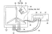
また、コイルの内部電極の電位を測定する内部電極電位測定装置は、コイル11の外表面を進退させ、第1〜第3内部電極14a,14b,14gの位置を把握し、各内部電極14a,14bの電位を測定する電位測定プローブ19と、この電位測定プロープ19からリード線を介してプローブ接続端子20に接続する非接触表面電位計20と、この非接触表面電位計20の波形出力端子21からリード線を介して接続する、例えば、交流電圧計またはオシロスコープ等の電圧測定装置22とを備え、交流電源23から導体12に印加する交番電圧と非接触表面電位計20から出力される電位とを電圧測定装置22で読み取るものである。第1〜第3絶縁層13a,13b,13cのうち、いずれかに導体冷却水の浸入があれば内部電極電位が上昇する現象を利用して、冷却水の浸入を検知するものである。
Further, the internal electrode potential measuring device for measuring the potential of the internal electrode of the coil advances and retracts the outer surface of the
また、コイル表面に測定電極を装着し、測定電極と、第1〜第2内部電極14a,14bおよび導体12との間の誘電特性を測定するに際し、コイル導体に交番電圧を印加し、図26に示すように、絶縁層13の表面の軸方向に沿って表面電位を測定し、内部電極の位置を確認し、適正な位置に測定電極24a,24b,24sを設け、誤差の少ない誘電特性を測定できるようにする。
Further, when a measurement electrode is mounted on the coil surface and the dielectric characteristics between the measurement electrode, the first to second
なお、交流電源23から導体13に印加される交番電圧は、正弦波であるが、矩形波、三角波でもよい。さらに、交番電圧の周波数は、第1〜第3絶縁層13a,13b,13cへの導体冷却水の漏水に伴う吸湿を考慮すると、低周波が好ましく、例えば、100Hz以下が好適である。
The alternating voltage applied to the
図6は、第1絶縁層13aから第3絶縁層13cに向って導体冷却水の漏水が順次浸入する場合、第1〜第3内部電極14a,14b,14gの電位を求める等価回路である。
FIG. 6 is an equivalent circuit for obtaining the potentials of the first to third
図中、導体12と第1内部電極14aとの静電容量をCaとし、第1内部電極14aと第2内部電極14bとの静電容量をCbとし、第2内部電極14bと第3内部電極14gとの静電容量をCcとする。
In the figure, the capacitance between the
なお、冷却水の浸入範囲が絶縁層13a内に留まる場合、導体12と内部電極14aとの間には、第1絶縁層13aの誘電損失を模擬した等価抵抗Raが設けられる。
When the intrusion range of the cooling water remains in the insulating
このような等価回路において、第1〜第3絶縁層13a,13b,13cへの導体冷却水の浸入がなければ、各内部電極14a,14bの電位は、印加電圧Eの静電容量Ca,Cb,Ccによる分圧で決まる。
In such an equivalent circuit, if the conductor cooling water does not enter the first to third insulating
このときの第1内部電極14aおよび第2内部電極14bのそれぞれの電位Va,Vbは、次式で表される。

第1絶縁層13aに導体冷却水の漏水があった場合、冷却水の比誘電率が非常に大きいので(冷却水の比誘電率が約80であるのに対し、乾燥した絶縁層の比誘電率が約4.5)、導体冷却水が漏水した第1絶縁層13aの静電容量Caが増加する。また、導体冷却水の漏水の電気伝導率は、絶縁層よりも極めて低いので、誘電損が大幅に増加する。この誘電損を模擬するために、導体12と第1内部電極14aとの間には等価抵抗Raが設けられる。
When there is leakage of the conductor cooling water in the first insulating
なお、静電容量Cb,Ccにも並列抵抗を必要とするが、導体冷却水の漏水がなければ十分に高いので省略している。 The capacitances Cb and Cc also require parallel resistance, but are omitted because they are sufficiently high if there is no leakage of the conductor cooling water.
各静電容量Ca,Cb,Ccを、例えばCa=1200pF、Cb=2000pF、Cc=3000pFとし、印加電圧EをE=100Vrmsの50Hz交流とする場合、第1絶縁層13aに導体冷却水の漏水がないとき、その電位Vaは、式(1)等からVa=50.0Vである。
When the respective capacitances Ca, Cb, Cc are, for example, Ca = 1200 pF, Cb = 2000 pF, Cc = 3000 pF, and the applied voltage E is 50 Hz alternating current of E = 100 Vrms, leakage of the conductor cooling water in the first insulating
次に、導体冷却水の漏水が第1絶縁層13aに浸入し、静電容量Caが、例えば3倍、具体的にはCa=3600pFに増加し、さらに誘電損失が増加し、誘電正接(tanδ)が0.2に増加した場合(健全な場合、一般に0.01程度以下)、第1内部電極14aの電位Vaを計算すると(計算式は複雑なため省略)、Va=75.6Vになり、健全な場合に較べて51%大きくなる。
Next, the leakage of the conductor cooling water enters the first insulating
また、第2内部電極14bの電位Vbも式(2)等に基づいて計算した結果も含めてまとめて表1に示す。
表1から、第2内部電極14bの電位も、導体冷却水の漏水により51%増加することがわかる。
From Table 1, it can be seen that the potential of the second
このように、導体冷却水の漏水があれば、その内部電極の電位が増加し、それと同時に絶縁破壊電圧が低下する。 Thus, if there is leakage of the conductor cooling water, the potential of the internal electrode increases, and at the same time, the dielectric breakdown voltage decreases.
したがって、内部電極の電位の変化と絶縁破壊電圧との間に何らかの相関関係があり、この相関関係を予め求めておけば、内部電極の電位から絶縁破壊電圧を推定することができると考えられる。 Therefore, there is some correlation between the change in potential of the internal electrode and the breakdown voltage. If this correlation is obtained in advance, it is considered that the breakdown voltage can be estimated from the potential of the internal electrode.
さて、図4〜図6で示したコイルの絶縁構造および内部電極電位測定装置を用いて導体からの冷却水が絶縁層に漏水した場合のコイル余寿命を推定する本発明に係るコイルの余寿命推定方法の実施形態を説明する。 Now, the remaining life of the coil according to the present invention for estimating the remaining life of the coil when the cooling water from the conductor leaks into the insulating layer using the coil insulation structure and the internal electrode potential measuring device shown in FIGS. An embodiment of the estimation method will be described.
図1は、本発明に係るコイルの余寿命推定方法の実施形態を示すブロック図である。 FIG. 1 is a block diagram showing an embodiment of a method for estimating the remaining life of a coil according to the present invention.
本実施形態に係るコイルの余寿命推定方法は、導体からの冷却水が絶縁層に漏水しているかどうかを確認し、導体冷却水が絶縁層に漏水している場合、コイルの絶縁破壊電圧を推定する第1工程(ステップ1)と、前記コイルの今後の運転条件から予測されるコイル温度および印加される電圧のうち、少なくともいずれか一方による前記コイルの絶縁破壊電圧の低下速度を求める第2工程(ステップ2)と、第1工程および第2工程から求めたデータを外挿し、絶縁破壊電圧がコイルの運転に必要な電圧まで低下する時期を求める第3工程(ステップ3)とを備えた構成になっている。 The remaining life estimation method of the coil according to the present embodiment confirms whether or not the cooling water from the conductor has leaked into the insulating layer, and if the conductor cooling water has leaked into the insulating layer, the dielectric breakdown voltage of the coil is determined. A first step of estimating (step 1) and a second step of obtaining a rate of decrease in the dielectric breakdown voltage of the coil by at least one of a coil temperature and an applied voltage predicted from future operating conditions of the coil A process (Step 2) and a third process (Step 3) for extrapolating the data obtained from the first process and the second process and determining when the dielectric breakdown voltage is reduced to a voltage required for the operation of the coil are provided. It is configured.
このような工程を備える本実施形態に係るコイルの余寿命推定方法は、先ず、第1工程(ステップ1の具体例は後述)で、導体から絶縁層へ冷却水の漏水の有無を表面電位測定プローブを介して内部電極の電位を測定し、導体冷却水の漏水がある場合、導体冷却水が漏水したコイルの絶縁破壊電圧を予め求めておいた内部電極の電位と絶縁破壊電圧の関係を示す図を用いて推定し、この推定値を図2上にA点としてプロットする。
The method for estimating the remaining life of the coil according to the present embodiment including such a process is first a surface potential measurement in the first process (a specific example of
次に、第2工程では、まず、コイルの今後の運転条件から予測されるコイル温度およびコイルの接続位置から印加される電圧を求める。次にそのコイルの運転条件における絶縁破壊電圧の低下速度を求める。 Next, in a 2nd process, the voltage applied from the coil temperature estimated from the future driving | running condition of a coil and the connection position of a coil is calculated | required first. Next, the rate of decrease in dielectric breakdown voltage under the operating conditions of the coil is determined.
最後に、第3工程では、図2のA点を通り、第2工程で求めた絶縁破壊電圧の低下速度の線Lを引き(外挿し)、コイルの運転に必要な電圧E0まで低下する時期、つまり寿命に達する時期B点を求める。そして、現時点(測定時点)からB点までの時間を余寿命として推定する。 Finally, in the third step, the line L of the breakdown voltage reduction rate obtained in the second step is drawn (extrapolated) through point A in FIG. 2, and the voltage E 0 is reduced to the voltage E 0 required for coil operation. Time B, that is, the time point B at which the life is reached is obtained. Then, the time from the current time (measurement time) to the point B is estimated as the remaining life.
なお、本実施形態に係るコイルの余寿命推定方法は、導体冷却水が漏水したコイルの絶縁破壊電圧を推定し、推定した一つのデータを基に余寿命を求めたが、この例に限らず、例えば、図3に示すように第1工程で、冷却水が漏水したコイルの絶縁破壊電圧を定期的にA1,A2,…,A6,…として求め、第2工程で、絶縁破壊電圧の経時変化カーブを求め、さらに、その経時変化カーブを外挿し、今後の絶縁破壊電圧の低下傾向を予測し、第3工程で、その経時変化カーブがコイルの運転に必要な電圧E0まで低下する時期B点を求めて、コイルの余寿命を推定してもよい。 The method for estimating the remaining life of the coil according to the present embodiment estimates the dielectric breakdown voltage of the coil in which the conductor cooling water has leaked, and calculates the remaining life based on the estimated data, but is not limited to this example. For example, as shown in FIG. 3, in the first step, the dielectric breakdown voltage of the coil that has leaked cooling water is periodically obtained as A 1 , A 2 ,..., A 6 ,. Obtain the time-dependent curve of the voltage, and extrapolate the time-dependent change curve to predict the future trend of decreasing breakdown voltage. In the third step, the time-dependent curve reaches the voltage E 0 required for coil operation. The remaining time of the coil may be estimated by obtaining a time point B that decreases.
このように、本実施形態に係るコイルの余寿命推定方法は、第1工程(ステップ1)で、絶縁破壊電圧を推定し、第2工程(ステップ2)で、絶縁破壊電圧の低下速度を求め、第3工程(ステップ3)で、第1工程および第2工程から求めたデータを外挿し、絶縁破壊電圧がコイルの運転に必要な電圧まで低下する余寿命(時期)を求めるので、コイルの余寿命を非破壊的にして簡易かつ容易に推定することができる。 As described above, in the method for estimating the remaining life of the coil according to the present embodiment, the breakdown voltage is estimated in the first step (step 1), and the rate of decrease in the breakdown voltage is obtained in the second step (step 2). In the third step (step 3), the data obtained from the first step and the second step is extrapolated to obtain the remaining life (time) at which the dielectric breakdown voltage drops to the voltage necessary for the coil operation. The remaining life can be estimated simply and easily by making it non-destructive.
次に、図1で示した本発明に係るコイルの余寿命推定方法における第1工程(ステップ1)および第2工程(ステップ2)を順を追って詳述する。 Next, the first step (step 1) and the second step (step 2) in the method for estimating the remaining life of the coil according to the present invention shown in FIG.
図7および図8は、第1工程(ステップ1)における絶縁破壊電圧を推定する際、第1実施形態に適用される絶縁破壊電圧−内部電極電位特性線図である。 FIGS. 7 and 8 are dielectric breakdown voltage-internal electrode potential characteristic diagrams applied to the first embodiment when estimating the dielectric breakdown voltage in the first step (step 1).
なお、図7は、絶縁層内に2つ(2層)の内部電極を設けた絶縁破壊電圧−内部電極電位特性線図である。また、図8は、絶縁層内に3つ(3層)の内部電極を設けた絶縁破壊電圧−内部電極電位特性線図である。 FIG. 7 is a breakdown voltage-internal electrode potential characteristic diagram in which two (two layers) internal electrodes are provided in the insulating layer. FIG. 8 is a breakdown voltage-internal electrode potential characteristic diagram in which three (three layers) internal electrodes are provided in the insulating layer.
図7および図8中、絶縁破壊電圧の初期値は、コイルの定格電圧や絶縁材料の種類等によって変る。以後、絶縁破壊電圧は、初期値に対する比をパーセントで表示する。 7 and 8, the initial value of the dielectric breakdown voltage varies depending on the rated voltage of the coil, the type of insulating material, and the like. Thereafter, the breakdown voltage is expressed as a percentage of the initial value.
第1工程(ステップ1)では、図4で示した電位測定プローブ19を絶縁層13の外表面を進退させるか、あるいは図26に示した測定電極24a,24b,24sに電位測定プローブ19を近接させて電位を測定する。
In the first step (step 1), the
測定した電位Va(2層内部電極)、Vb(3層内部電極)のそれぞれの加えた電圧Eに対する比Va/E、Vb/Eを基に、予め作成しておいた絶縁破壊電圧−内部電極電位特性線図から絶縁破壊電圧が求められる。 Based on the ratios Va / E and Vb / E of the measured potentials Va (two-layer internal electrode) and Vb (three-layer internal electrode) to the applied voltage E, the dielectric breakdown voltage-internal electrode prepared in advance. The dielectric breakdown voltage is obtained from the potential characteristic diagram.
このように、本実施形態は、絶縁破壊電圧−内部電極電位特性線図を実験データ等で予め作成しているので、測定した電位Va,Vbから絶縁破壊電圧を容易に求めることができる。 As described above, in this embodiment, since the dielectric breakdown voltage-internal electrode potential characteristic diagram is prepared in advance by experimental data or the like, the dielectric breakdown voltage can be easily obtained from the measured potentials Va and Vb.
なお、内部電極の電位は、直接には測定できず、絶縁層の外表面の電位を測定するものであるが、両者は近い値であるので、説明を簡単にするために、以後、「内部電極電位を測定する」あるいは「内部電極電位」などと記す。 Note that the potential of the internal electrode cannot be measured directly, but the potential of the outer surface of the insulating layer is measured. However, since both values are close to each other, in order to simplify the explanation, hereinafter “internal It is referred to as “measuring electrode potential” or “internal electrode potential”.
図9および図10は、第1工程(ステップ1)における第2実施形態として適用される絶縁破壊電圧−内部電極電位の対初期値比特性線図である。 FIG. 9 and FIG. 10 are characteristic diagrams of the breakdown voltage-internal electrode potential to initial value ratio applied as the second embodiment in the first step (step 1).
本実施形態は、内部電極電位を測定するとき、導体に供給される冷却水の絶縁層への漏水により電位が上昇するが、その上昇変化率が重要であることに鑑み、各内部電極電位の初期値に対する比と絶縁破壊電圧の関係を予め求めておけば、絶縁破壊電圧を容易に推定することができる。 In this embodiment, when measuring the internal electrode potential, the potential rises due to water leakage to the insulating layer of the cooling water supplied to the conductor. If the relationship between the ratio to the initial value and the breakdown voltage is obtained in advance, the breakdown voltage can be easily estimated.
図9は、2つ(2層)の内部電極を備えるコイルの内部電極aの電位V14aの初期値に対する比と、絶縁破壊電圧の関係を示した絶縁破壊電圧−内部電極電位の対初期値比特性線図である。 FIG. 9 shows the relationship between the ratio of the potential V14a of the internal electrode a of the coil having two (two layers) internal electrodes to the initial value and the breakdown voltage-internal electrode potential to initial value ratio showing the relationship between the breakdown voltage. It is a characteristic diagram.
また、図10は、3つ(3層)の内部電極を備えるコイルの内部電極14a,14bの電位Va,Vbの初期値(それぞれVa0,Vb0)に対する比と絶縁破壊電圧の関係を示した絶縁破壊電圧−内部電極電位の対初期値比特性線図である。
FIG. 10 shows the relationship between the ratio and the breakdown voltage with respect to the initial values (Va 0 and Vb 0 ) of the potentials Va and Vb of the
ここで、初期値Va0,Vb0は、コイルの製造持または運転時の初期段階に測定するか、あるいは電位Va,Vbの測定時、多数のコイルを測定し、測定値の分布の中で正常と判断される値を求める。後者の具体例として、最も簡単な方法は、全測定データの中央値を採ればよい。 Here, the initial values Va 0 and Vb 0 are measured at the initial stage of manufacture and operation of the coil, or when measuring the potentials Va and Vb, a large number of coils are measured, Find a value that is considered normal. As a specific example of the latter, the simplest method may be to take the median value of all measurement data.
以上のように、図9および図10で示した絶縁破壊電圧−内部電極電位の対初期値比特性線図を実験等で予め作成しておけば、内部電極電位を測定し、初期値に対する上昇率を求めることができ、絶縁破壊電圧を推定することができる。 As described above, if the dielectric breakdown voltage-internal electrode potential vs. initial value ratio characteristic diagram shown in FIG. 9 and FIG. 10 is prepared in advance by experiments or the like, the internal electrode potential is measured and increased with respect to the initial value. The rate can be determined and the breakdown voltage can be estimated.
図11は、第1工程(ステップ1)における第3実施形態として適用される絶縁破壊電圧−隣接内部電極電位比特性線図である。 FIG. 11 is a characteristic diagram of dielectric breakdown voltage-adjacent internal electrode potential ratio applied as the third embodiment in the first step (step 1).
本実施形態は、内部電極を3つ(3層)以上備えるコイル、つまり浮遊電位の内部電極を2層以上備えるコイルの層状配置のうち、隣接する2つの内部電極電位の比(浮遊電位の内部電極を2層にする場合、Vb/Va)は、その2つの内部電極間に導体冷却水の漏水が浸入しなければ一定値であり(表1参照)、導体冷却水の漏水が浸入すれば増加する。 In the present embodiment, the ratio of two adjacent internal electrode potentials (inside of the floating potential) in a layered arrangement of coils having three (three layers) internal electrodes, that is, two or more layers of floating potential internal electrodes. When the electrode has two layers, Vb / Va) is a constant value unless the conductor cooling water leaks between the two internal electrodes (see Table 1), and if the conductor cooling water leaks, To increase.
この2つの内部電極電位の比と絶縁破壊電圧との関係を実験等で予め求めておき、測定したコイルの隣接する2つの内部電極電位の比から絶縁破壊電圧を推定するものである。 The relationship between the ratio between the two internal electrode potentials and the dielectric breakdown voltage is obtained in advance by experiments or the like, and the dielectric breakdown voltage is estimated from the ratio between the two internal electrode potentials adjacent to the measured coil.
このように、本実施形態は、絶縁破壊電圧−隣接内部電極電位比特性線図を求めておけば、絶縁破壊電圧を容易に推定することができる。 Thus, this embodiment can estimate a dielectric breakdown voltage easily, if the dielectric breakdown voltage-adjacent internal electrode potential ratio characteristic diagram is calculated | required.
図12は、第1工程(ステップ1)における第4実施形態として適用される絶縁破壊電圧−誘電特性線図である。 FIG. 12 is a dielectric breakdown voltage-dielectric characteristic diagram applied as the fourth embodiment in the first step (step 1).
導体に供給される導体冷却水の漏水が絶縁層内に浸入すると、絶縁層の誘電特性は変化する。 When the leakage of the conductor cooling water supplied to the conductor enters the insulating layer, the dielectric characteristics of the insulating layer change.
誘電特性には、静電容量、誘電損率、誘電損失角、誘電正接(tanδ)、力率などがある。これらは、漏水が絶縁層内に浸入してもすべて利用できる。 Dielectric characteristics include capacitance, dielectric loss factor, dielectric loss angle, dielectric loss tangent (tan δ), power factor, and the like. All of these can be used even if water leaks into the insulating layer.
しかし、前2者(静電容量、誘電損率)は内部電極の大きさ、絶縁層の厚さが変ると変化するに対し、後ろ3者(誘電損失角、誘電正接、力率)は内部電極の大きさ、絶縁層の厚さの変化に影響を受けない。 However, the former two (capacitance, dielectric loss factor) change as the size of the internal electrode and the thickness of the insulating layer change, while the latter three (dielectric loss angle, dielectric loss tangent, power factor) are internal. Unaffected by changes in electrode size and insulating layer thickness.
一方、コイルエンド部のクリップの周辺は、作業者が手作業で絶縁テープを導体に巻き付けるため、絶縁層の厚みが一定しない。また、コイルエンド部には、コイルを固定するための固定部材が設けられており、コイルによって同じ大きさの測定電極を設けることができない場合がある。 On the other hand, since the operator manually winds the insulating tape around the conductor around the clip of the coil end portion, the thickness of the insulating layer is not constant. Further, the coil end portion is provided with a fixing member for fixing the coil, and there may be a case where measurement electrodes having the same size cannot be provided by the coil.
以下の実施例は、このような点を勘案して後ろ3者のうち、例えば誘電正接(tanδ)を選択した。 In the following examples, the dielectric loss tangent (tan δ), for example, was selected from the back three considering such points.
図12に示す絶縁破壊電圧−誘電特性線図は、3つ(3層)の内部電極を備えるコイルに適用するもので、導体から絶縁層に冷却水の漏水があった後の、導体上の誘電正接tanδ0、第1内部電極a上の誘電正接tanδa、第2内部電極b上の誘電正接tanδbのそれぞれを線図化したものである。 The dielectric breakdown voltage-dielectric characteristic diagram shown in FIG. 12 is applied to a coil having three (three layers) internal electrodes. On the conductor after the coolant leaks from the conductor to the insulating layer. Each of the dielectric loss tangent tan δ0, the dielectric loss tangent tan δa on the first internal electrode a, and the dielectric loss tangent tan δb on the second internal electrode b is plotted.
本実施形態は、構造上の制約があって、同じ大きさの測定電極を絶縁層に装着できない場合でも、絶縁層への導体冷却水の漏水を容易にして確実に把握することができる。 In the present embodiment, even when measurement electrodes having the same size cannot be mounted on the insulating layer due to structural limitations, the leakage of the conductor cooling water to the insulating layer can be easily and reliably grasped.
次に、図13から図16を引用して第1工程(ステップ1)における絶縁層への導体冷却水の漏水確認手段としての第5実施形態を説明する。 Next, a fifth embodiment as a means for confirming leakage of conductor cooling water to the insulating layer in the first step (step 1) will be described with reference to FIGS.
本実施形態は、絶縁層へ導体冷却水の漏水があると、誘電特性が導体冷却水の漏水量に応じて周波数依存性が高くなるとことに着目したものであり、3つ(3層)の内部電極と測定電極との間の静電容量の周波数特性を図13に示し、静電容量と静電正接の積の周波数特性を図14に示す。 This embodiment pays attention to the fact that when there is leakage of the conductor cooling water to the insulating layer, the dielectric property becomes frequency dependent depending on the amount of leakage of the conductor cooling water, and there are three (three layers). FIG. 13 shows the frequency characteristic of the capacitance between the internal electrode and the measurement electrode, and FIG. 14 shows the frequency characteristic of the product of the capacitance and the electrostatic tangent.
これら図13、図14において、実線は乾燥した絶縁層の特性、点線は約33%の絶縁層厚さまで導体冷却水の浸入があった場合、破線は約70%の絶縁層厚さまで導体冷却水の浸入があった場合のそれぞれを示す。 In FIG. 13 and FIG. 14, the solid line indicates the characteristics of the dried insulating layer, the dotted line indicates that the conductor cooling water has entered to an insulating layer thickness of approximately 33%, and the broken line indicates the conductor cooling water to approximately 70% of the insulating layer thickness. Each of the cases where there was intrusion.
これら図13,14から、絶縁層への導体冷却水の漏水がない場合、誘電特性は周波数依存性が非常に小さいのに対し、絶縁層への導体冷却水の漏水がある場合、誘電特性は周波数依存性が高くなっている。 13 and 14, when there is no leakage of the conductor cooling water to the insulating layer, the dielectric characteristic has a very small frequency dependence, whereas when there is a leakage of the conductor cooling water to the insulating layer, the dielectric characteristic is The frequency dependency is high.
例えば、1kHzの誘電特性/10kHzの誘電特性と導体冷却水の絶縁層への浸入割合の関係を、図15に示す絶縁破壊電圧−誘電特性の周波数変化線図で表す。 For example, the relationship between the dielectric characteristics of 1 kHz / 10 dielectric characteristics and the penetration ratio of the conductor cooling water into the insulating layer is represented by a frequency change diagram of dielectric breakdown voltage-dielectric characteristics shown in FIG.
この絶縁破壊電圧−誘電特性の周波数変化線図から、誘電特性の周波数依存性は、絶縁破壊電圧と強い関係になっていることがわかる。 From the frequency change diagram of the dielectric breakdown voltage-dielectric characteristics, it can be seen that the frequency dependence of the dielectric characteristics has a strong relationship with the dielectric breakdown voltage.
一方、2つ(2層)の内部電極を備えたコイルの絶縁破壊電圧−誘電特性の周波数変化線図を図16に示す。 On the other hand, FIG. 16 shows a frequency change diagram of dielectric breakdown voltage-dielectric characteristics of a coil having two (two layers) internal electrodes.
この図16において、実線は内部電極を持たないクリップに近い導体上の絶縁層表面に装着した測定電極と導体間の静電容量と誘電正接との積の1kHzと10kHzの測定値比、破線は内部電極上の絶縁層外表面に装着した測定電極と導体間の静電容量と誘電正接との積の1kHzと10kHzの測定値の比を示す。 In FIG. 16, the solid line is the measurement value ratio of 1 kHz and 10 kHz of the product of the capacitance and the dielectric loss tangent between the measurement electrode mounted on the surface of the insulating layer on the conductor near the clip having no internal electrode and the conductor, and the broken line is The ratio of the measured value of 1 kHz and 10 kHz of the product of the capacitance between the measurement electrode mounted on the outer surface of the insulating layer on the internal electrode and the conductor and the dielectric loss tangent is shown.
図16に示した絶縁破壊電圧−誘電特性の周波数変化率線図は、同一電極を用い、同一個所で周波数だけを変化させて測定するため、データにばらつきが少なく、内部電極の大きさ、絶縁層厚さに測定結果が依存しない点で測定精度が高い。 The frequency change rate diagram of the dielectric breakdown voltage-dielectric characteristics shown in FIG. 16 uses the same electrode and changes only the frequency at the same location, so there is little variation in data, the size of the internal electrode, and the insulation Measurement accuracy is high in that the measurement result does not depend on the layer thickness.
このように、本実施形態は、実験等で予め絶縁破壊電圧−誘電特性の周波数変化率線図を取得しておけば、少なくとも2つの周波数で誘電特性を測定し、その比をとれば絶縁破壊電圧を簡単にして容易に推定することができる。 As described above, according to the present embodiment, if a frequency change rate diagram of dielectric breakdown voltage-dielectric characteristics is acquired in advance by an experiment or the like, the dielectric characteristics are measured at at least two frequencies, and if the ratio is taken, the dielectric breakdown is obtained. The voltage can be simplified and easily estimated.
図17および図18は、第1工程(ステップ1)における第6実施形態として適用される絶縁破壊電圧−内部電極電位特性線図である。 FIGS. 17 and 18 are dielectric breakdown voltage-internal electrode potential characteristic diagrams applied as the sixth embodiment in the first step (step 1).
コイル絶縁層の絶縁破壊電圧を推定する方法は、すでに図7〜図11に示した絶縁破壊電圧−内部電極電位特性線図、絶縁破壊電圧−内部電極電位の対初期値比特性線図、絶縁破壊電圧−隣接内部電極電位比特性線図のそれぞれを用い、測定した内部電極電位、内部電極電位の対初期値比、隣接内部電極電位比のそれぞれに対応する絶縁破壊電圧値を求めていた。 The method of estimating the dielectric breakdown voltage of the coil insulating layer includes the dielectric breakdown voltage-internal electrode potential characteristic diagram, the dielectric breakdown voltage-internal electrode potential ratio characteristic curve, and the insulation already shown in FIGS. Using each of the breakdown voltage-adjacent internal electrode potential ratio characteristic diagrams, the measured internal electrode potential, the internal electrode potential to initial value ratio, and the dielectric breakdown voltage value corresponding to the adjacent internal electrode potential ratio were obtained.
この場合、1つの測定値に対し、2の絶縁破壊電圧値が求まることがある。 In this case, two breakdown voltage values may be obtained for one measurement value.
このようなケースに対する絶縁破壊電圧値を求め方を、図17を引用して説明する。 A method of obtaining the dielectric breakdown voltage value for such a case will be described with reference to FIG.
図17は、すでに示した図8の内部電極を3つ(3層)備えたコイルの内部電極aの電位Vaと絶縁破壊電圧との関係を示す絶縁破壊電圧−内部電極電位特性線図である。 FIG. 17 is a breakdown voltage-internal electrode potential characteristic diagram showing the relationship between the potential Va of the internal electrode a and the breakdown voltage of the coil having the three internal electrodes (three layers) shown in FIG. .
図中、電位Vaが83%の場合、絶縁破壊電圧は59%(B点)、17%(C点)の2つの値が得られる。 In the figure, when the potential Va is 83%, the dielectric breakdown voltage has two values of 59% (point B) and 17% (point C).
一方、内部電極a上の絶縁層の誘電正接tanδaは、図18に示すように、1.8%(B′領域)である。この誘電正接tanδa=1.8%は、急激に上昇する前段階(B′)であり、絶縁破壊電圧が約50%以上と考えられる。 On the other hand, the dielectric loss tangent tan δa of the insulating layer on the internal electrode a is 1.8% (B ′ region) as shown in FIG. This dielectric loss tangent tan δa = 1.8% is the pre-stage (B ′) where the dielectric loss tangentially rises, and the dielectric breakdown voltage is considered to be about 50% or more.
この誘電正接tanδa=1.8%のとき、絶縁破壊電圧が約50%以上であることを勘案すると、上述電位Vaが83%のとき、絶縁破壊電圧は59%(図17のB点)と推定される。 Considering that the dielectric breakdown voltage tan δa = 1.8% is about 50% or more, the dielectric breakdown voltage is 59% (point B in FIG. 17) when the potential Va is 83%. Presumed.
ちなみに、もし絶縁破壊電圧が17%(図17のC点)まで低下しているとすれば、図18から誘電正接tanδa=69%(C′点)と読み取れ、いくら測定精度が悪いとしても、誘電正接tanδa=2%のものを誘電正接tanδa=69%と測定することはあり得ない。 Incidentally, if the breakdown voltage is reduced to 17% (point C in FIG. 17), it can be read from FIG. 18 that the dielectric loss tangent tan δa = 69% (point C ′), no matter how bad the measurement accuracy is, A dielectric loss tangent tan δa = 2% cannot be measured as a dielectric tangent tan δa = 69%.
したがって、絶縁破壊電圧は、17%まで低下することはあり得ず、59%と推定される。 Therefore, the dielectric breakdown voltage cannot be reduced to 17% and is estimated to be 59%.
このように、本実施形態は、絶縁破壊電圧−内部電極電位特性線図から絶縁破壊電圧を求める場合、絶縁破壊電圧−誘電特性線図を組合せて絶縁破壊電圧を判定するので、適正な絶縁破壊電圧値を求めることができる。 As described above, in this embodiment, when determining the breakdown voltage from the breakdown voltage-internal electrode potential characteristic diagram, the breakdown voltage is determined by combining the breakdown voltage-dielectric characteristic diagram. The voltage value can be obtained.
図19は、第1工程(ステップ1)における第7実施形態として適用される絶縁破壊電圧−内部電極電位特性線図である。 FIG. 19 is a breakdown voltage-internal electrode potential characteristic diagram applied as the seventh embodiment in the first step (step 1).
コイル絶縁層の絶縁破壊電圧を推定する際、上述第6実施形態では、絶縁破壊電圧−内部電極電位特性線図等と絶縁破壊電圧−誘電特性線図とを組み合わせ、求めた2つの絶縁破壊電圧値のうち、適正値を判定したが、本実施形態では、求めた2つの絶縁破壊電圧値のうち、適正値の判定を、絶縁破壊電圧値の経時的変化から行うものである。 In estimating the dielectric breakdown voltage of the coil insulating layer, in the sixth embodiment, two dielectric breakdown voltages obtained by combining the dielectric breakdown voltage-internal electrode potential characteristic diagram and the like and the dielectric breakdown voltage-dielectric characteristic diagram are combined. Of the two values, the appropriate value is determined, but in the present embodiment, the appropriate value of the two obtained breakdown voltage values is determined from the temporal change in the breakdown voltage value.
図19は、その一例である。 FIG. 19 shows an example.
例えば、1年前に測定した電位Vaが65%の場合、上述の誘電正接tanδaの測定結果と併用すると、絶縁破壊電圧は71%(A点)と推定される。 For example, when the potential Va measured one year ago is 65%, the dielectric breakdown voltage is estimated to be 71% (point A) when used together with the measurement result of the above-described dielectric loss tangent tan δa.
一方、今回測定した電位Vaが83%の場合、導体冷却水の絶縁層への漏水浸入速度から絶縁破壊電圧は、1年間で17%(C点)まで一気に低下することは考えられず、59%(B点)と推定される。 On the other hand, when the potential Va measured this time is 83%, it is unlikely that the dielectric breakdown voltage drops to 17% (C point) in one year due to the leakage rate of the conductor cooling water into the insulating layer. % (Point B).
このように、本実施形態は、絶縁破壊電圧−内部電極電位特性線図から求めた2つの絶縁破壊電圧値に対し、測定した電位の経時的変化を考慮するので、適正な絶縁破壊電圧値を選択することができる。 As described above, in the present embodiment, since the time-dependent change of the measured potential is considered with respect to the two breakdown voltage values obtained from the breakdown voltage-internal electrode potential characteristic diagram, an appropriate breakdown voltage value is set. You can choose.
次に、コイルの余寿命推定方法の第1実施形態の第2工程(ステップ2)における第1実施形態として適用される絶縁破壊電圧の低下速度を求める方法を説明する。 Next, a description will be given of a method for obtaining the rate of decrease in dielectric breakdown voltage applied as the first embodiment in the second step (step 2) of the first embodiment of the method for estimating the remaining life of the coil.
本実施形態は、導体冷却水の絶縁層への浸入のない6本のコイルのクリップを被覆する絶縁層の一部を除去するとともに、1本の中空素線に、例えば、直径0.3mmの穴を開け、中空素線から漏水の流出を阻止しないように穴の周囲に隙間を確保させ、再絶縁を行ったコイルを使用した。 The present embodiment removes a part of the insulating layer covering the clip of the six coils that does not enter the insulating layer of the conductor cooling water, and, for example, has a diameter of 0.3 mm on one hollow wire. A coil was used that was re-insulated by making a hole, ensuring a gap around the hole so as not to prevent leakage of water leakage from the hollow wire.
試験の際、コイル2本ずつに、例えば、温度95℃、80℃、70℃のそれぞれに制御したイオン交換水を循環させた。 During the test, ion-exchanged water controlled at temperatures of 95 ° C., 80 ° C., and 70 ° C., for example, was circulated for every two coils.
そして、定期的に内部電極電位を測定し、漏水の絶縁層への浸入程度、および絶縁破壊電圧−内部電極電位特性線図を用いて、絶縁破壊電圧を推定した。また、各温度(95℃,80℃,70℃)のイオン交換水を循環させたコイル2本を異なる時期に、左右のコイルエンド部を別々に絶縁破壊させた。 Then, the internal electrode potential was measured periodically, and the dielectric breakdown voltage was estimated using the degree of penetration of water leakage into the insulating layer and the breakdown voltage-internal electrode potential characteristic diagram. In addition, the left and right coil end portions were separately subjected to dielectric breakdown at different times in two coils in which ion-exchanged water at each temperature (95 ° C., 80 ° C., 70 ° C.) was circulated.
絶縁破壊後、イオン交換水の温水循環時間と絶縁破壊電圧との関係を図20に示すように、絶縁破壊電圧−温水循環時間線図として作成した。 After the dielectric breakdown, the relationship between the hot water circulation time of the ion exchange water and the dielectric breakdown voltage was created as a dielectric breakdown voltage-warm water circulation time diagram as shown in FIG.
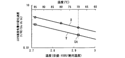
次に、循環水の温度と絶縁破壊電圧の低下速度との関係を求めるために、本実施形態では、図20に示される勾配(傾き)に基づいて図21で示される縦軸を絶縁破壊電圧の低下速度の対数にし、横軸に絶対温度の逆数を採った線図(アレーニウスプロット図と称す)を作成した。 Next, in order to obtain the relationship between the temperature of the circulating water and the rate of decrease in the breakdown voltage, in the present embodiment, the vertical axis shown in FIG. 21 is represented by the breakdown voltage based on the gradient (slope) shown in FIG. A graph (referred to as Arrhenius plot diagram) was made with the logarithm of the rate of decrease in the value and the reciprocal of absolute temperature on the horizontal axis.
このように、本実施形態は、図21に示す絶縁破壊電圧低下速度−温度線図を予め作成しておくので、任意の温度における絶縁破壊電圧の低下速度を容易に求めることができる。 As described above, in this embodiment, since the breakdown voltage decrease rate-temperature diagram shown in FIG. 21 is prepared in advance, the breakdown voltage decrease rate at an arbitrary temperature can be easily obtained.
なお、ろう付け部分の欠陥の程度やろう付け部分の腐食状況は、種々変化する。このため、上述の中空素線に開ける穴の大きさや数を変えてテストを行えば、絶縁層に浸入する漏水量の違いから漏水浸入速度、絶縁破壊電圧の低下速度におよぼす影響を把握することができる。 The degree of defects in the brazed part and the corrosion status of the brazed part vary variously. For this reason, if the test is carried out by changing the size and number of holes to be formed in the hollow wire described above, the influence on the leakage rate and the breakdown voltage reduction rate can be grasped from the difference in the amount of leakage entering the insulating layer. Can do.
また、上記実施例では、素線に人工的に中空素線に穴をあけ水を漏出させたが、発電機の運転中に水漏れを起こしたコイルを発電機から抜取り、温水循環試験の試料として用いてもよい。この場合は、ばらつきが大きくなるが、現実に近い条件で試験できる利点がある。 Further, in the above embodiment, the hollow wire was artificially made in the strand and water was leaked out, but the coil that caused water leakage during the operation of the generator was removed from the generator, and the sample for the hot water circulation test It may be used as In this case, the variation becomes large, but there is an advantage that the test can be performed under conditions close to reality.
図22、図23および図24は、コイルの余寿命推定方法の第1実施形態の第2工程(ステップ2)における第2および第3実施形態として適用される絶縁破壊電圧の低下速度を求める方法を説明するための線図である。 22, FIG. 23, and FIG. 24 show a method for obtaining the rate of decrease in breakdown voltage applied as the second and third embodiments in the second step (step 2) of the first embodiment of the method for estimating the remaining life of the coil. FIG.
本実施形態は、1温度によるコイルの温水循環試験と絶縁層の切出し試験片の複数温度による湿熱劣化試験とを併用して任意の温度における絶縁破壊電圧の低下速度を求めたものである。 In the present embodiment, the rate of decrease in the dielectric breakdown voltage at an arbitrary temperature is obtained by combining the hot water circulation test of the coil at one temperature and the wet heat degradation test at a plurality of temperatures of the cut specimen of the insulating layer.
すなわち、水と温度による絶縁層の劣化(湿熱劣化と称する)が進むにつれ、絶縁層の中の樹脂、例えばエポキシ樹脂の化学結合が加水分解により変質し、特定の基の含有率が変化する。この特定の基の代表的なものがエステル基である。樹脂中にエステル基が存在する場合、エステル基が加水分解により切断され、有機酸と水酸基に変化する。 That is, as the deterioration of the insulating layer due to water and temperature (referred to as wet heat deterioration) proceeds, the chemical bond of a resin, for example, an epoxy resin in the insulating layer is altered by hydrolysis, and the content of a specific group changes. A representative of this particular group is an ester group. When an ester group is present in the resin, the ester group is cleaved by hydrolysis to change into an organic acid and a hydroxyl group.
したがって、湿熱劣化の進展度合とエステル基の減少度合、あるいは有機酸または水酸基の増加度合との間には相関関係がある。 Therefore, there is a correlation between the degree of progress of wet heat degradation and the degree of ester group reduction or the degree of organic acid or hydroxyl group increase.
本実施形態は、このような現象を利用し、湿熱劣化の進展速度の温度依存性を絶縁層の試験サンプル(切出し試験片)で試験し、実コイルに用いる一つの温度の劣化試験結果と合わせて、任意の温度の絶縁破壊電圧の低下速度を求めるものである。 In this embodiment, using such a phenomenon, the temperature dependence of the rate of progress of wet heat degradation is tested with a test sample (cut-out test piece) of the insulating layer and combined with the result of one temperature degradation test used for the actual coil. Thus, the rate of decrease in dielectric breakdown voltage at an arbitrary temperature is obtained.
ここで求めたい絶縁破壊電圧の低下速度(−d(BDV)/dt,BDV:絶縁破壊電圧、t:時間)は、以下のように変形される。
式(3)の右辺の第1項は、実コイルの温水循環試験または実運転コイルから求め、第2項は絶縁層の切出し試験片の湿熱劣化試験において求める。 The first term on the right side of Equation (3) is obtained from the hot water circulation test or actual operation coil of the actual coil, and the second term is obtained from the wet heat deterioration test of the cut specimen of the insulating layer.
以下に、湿熱劣化の進展速度の温度依存性に基づく絶縁破壊電圧の低下速度を求める方法を詳述する。 Hereinafter, a method for obtaining the rate of decrease in dielectric breakdown voltage based on the temperature dependence of the rate of progress of wet heat degradation will be described in detail.
本実施形態において、先ずA工程において、1温度によるコイルの温水循環試験では、コイルの余寿命推定方法の第1実施形態の第2工程(ステップ2)における第1実施形態で述べた温水循環試験と全く同様な試験を1温度だけで行なう。試験温度は、試験期間により決めればよいが、高い温度の方が試験期間を短くすることができる。一例として95℃の温度のイオン交換水を複数本の導体に循環させ、2ヶ月後と5ヶ月後にコイルの絶縁破壊試験を行い、絶縁破壊電圧を求めた。試験結果から絶縁破壊電圧−温水循環時間線図(図20の95℃のプロット)を作成し、その傾きとしてコイルの95℃1温度における絶縁破壊電圧の低下速度が求められる。 In this embodiment, first, in step A, in the hot water circulation test of the coil at one temperature, the hot water circulation test described in the first embodiment in the second step (step 2) of the first embodiment of the method for estimating the remaining life of the coil Exactly the same test is performed at one temperature. The test temperature may be determined depending on the test period, but a higher temperature can shorten the test period. As an example, ion-exchanged water having a temperature of 95 ° C. was circulated through a plurality of conductors, and a dielectric breakdown test of the coil was performed after 2 months and 5 months to obtain a dielectric breakdown voltage. A breakdown voltage-warm water circulation time diagram (plot at 95 ° C. in FIG. 20) is prepared from the test results, and the rate of decrease in the breakdown voltage at a temperature of 95 ° C. of the coil is determined as the slope.
コイルの絶縁破壊試験後、本実施形態は絶縁層を解体し、絶縁層をサンプリングし、絶縁層に含まれる特定の基Sとしてエステル基の含有率Gaを赤外吸収スペクトルで測定する。 After the dielectric breakdown test of the coil, the present embodiment disassembles the insulating layer, samples the insulating layer, and measures the ester group content Ga as a specific group S contained in the insulating layer by an infrared absorption spectrum.
次いでB工程において、導体冷却水の漏水がない場合の絶縁層は、例えば40mm×50mmの長方形形状にした切出し試験片として切り出し、導体冷却水温度を、例えば、95℃、80℃、70℃に制御したイオン交換水に浸漬し、予め定められた時間ごとに取り出し、絶縁層に含まれるエステル基含有率Gbを赤外吸収スペクトルで測定する。 Next, in step B, the insulating layer when there is no leakage of the conductor cooling water is cut out as a cut specimen having a rectangular shape of, for example, 40 mm × 50 mm, and the conductor cooling water temperature is set to 95 ° C., 80 ° C., 70 ° C., for example. It is immersed in the controlled ion exchange water, taken out every predetermined time, and the ester group content Gb contained in the insulating layer is measured by an infrared absorption spectrum.
なお、ここで、エステル基の含有率Ga、Gbはその絶対値より、初期状態(未劣化状態)の絶縁層中のエステル基含有率Ga0、Gb0からの変化が重要であるので、両者の差ΔGa、ΔGb(ΔG=|G−G0|)を用いてもよい。以下のデータ処理においてはエステル基含有率Ga、Gbの代わりに、ΔGa、ΔGbを用いて説明することにする。Ga、Gbを用いれば、以下の説明で用いる線形尺度のグラフ図22と図23がGa0、Gb0だけ平行移動したグラフとなる。これらのグラフの傾きを用いるので最終的な結果は同じとなる。 Here, since the content rates Ga and Gb of the ester groups are more important than their absolute values, changes from the ester group content rates Ga 0 and Gb 0 in the insulating layer in the initial state (undegraded state) are important. Differences ΔGa and ΔGb (ΔG = | G−G 0 |) may be used. The following data processing will be described using ΔGa and ΔGb instead of the ester group contents Ga and Gb. If Ga and Gb are used, graphs of linear scales used in the following description will be graphs in which FIGS. 22 and 23 are translated by Ga 0 and Gb 0 . Since the slopes of these graphs are used, the final result is the same.
このようにして得られたエステル基含有率の初期値からの変化ΔGaおよびΔGbと劣化時間との関係を図22に示す。また、コイルの絶縁破壊電圧とそのコイルの絶縁層中のエステル基含有率Gaの初期値からの変化量ΔGaとの関係を図23に示す。図23で示した線図のプロットの回帰直線の勾配(傾き)が、コイルの絶縁破壊電圧のエステル含有率依存性Kaであり、式(3)の右辺第1項に対応する。 The relationship between the changes ΔGa and ΔGb from the initial value of the ester group content thus obtained and the deterioration time is shown in FIG. FIG. 23 shows the relationship between the breakdown voltage of the coil and the amount of change ΔGa from the initial value of the ester group content Ga in the insulating layer of the coil. The slope (slope) of the regression line in the plot of the diagram shown in FIG. 23 is the ester content dependency Ka of the dielectric breakdown voltage of the coil, and corresponds to the first term on the right side of Equation (3).
次にC工程において、図22で示した線図の勾配(傾き)から得られるエステル含有率の変化速度(コイルに対してはUa、切出し試験片に対してはUb)と劣化温度との関係をアレーニウスプロットし、図24に示す。 Next, in step C, the relationship between the change rate of ester content (Ua for the coil and Ub for the cut specimen) obtained from the gradient (slope) of the diagram shown in FIG. 22 and the deterioration temperature. Arrhenius plot is shown in FIG.
図24において、絶縁層の切出し片による3つの温度(95℃,80℃,70℃)のプロット点の回帰直線Xを引き、さらに、実コイルのエステル含有率の時間変化速度のプロット点を通り回帰直線Xに平行な実コイルのエステル含有率の変化速度の温度依存性を示す推定直線Yを描く。この推定直線Yから任意温度におけるコイル絶縁層中のエステル含有率の時間変化速度Ucが求められる。例えば、発電機の運転時のコイル導体温度が70℃の場合は、図24からエステル含有率の時間変化速度Ucが0.08/年と求められる(推定される)。この所定温度におけるエステル含有率の時間変化速度Ucが式(3)の右辺の第2項に対応する。 In FIG. 24, a regression line X of plot points of three temperatures (95 ° C., 80 ° C., and 70 ° C.) by the cut pieces of the insulating layer is drawn, and further, through the plot points of the time change rate of the ester content of the actual coil. An estimated straight line Y indicating the temperature dependence of the rate of change of the ester content of the actual coil parallel to the regression line X is drawn. From this estimated straight line Y, the time change rate Uc of the ester content in the coil insulating layer at an arbitrary temperature is obtained. For example, when the coil conductor temperature during operation of the generator is 70 ° C., the time change rate Uc of the ester content rate is obtained as 0.08 / year from FIG. 24 (estimated). The time change rate Uc of the ester content at the predetermined temperature corresponds to the second term on the right side of the equation (3).
このようにして求めた(コイルの絶縁破壊電圧のエステル含有率依存性Ka)と(コイルの運転温度におけるエステル含有率の時間変化速度Uc)の積がコイルの運転温度における絶縁破壊電圧の低下速度である。 The product of (ester content dependency Ka of coil breakdown voltage) and (time change rate Uc of ester content at coil operating temperature) obtained in this way is the rate of decrease in breakdown voltage at coil operating temperature. It is.
なお、本実施例では、劣化量としてエステル含有率を用いたが、これに限らず、有機酸の含有率の増加を化学的分析機器を用いて分析し、式(3)のエステル基の代わりに用いてもよい。また、樹脂の種類によっては加水分解により、この他の基がより感度よく変化することが分かっている場合、その特定の基を分析して用いればよい。 In this example, the ester content was used as the amount of deterioration, but this is not limiting, and the increase in the content of organic acid is analyzed using a chemical analyzer, and instead of the ester group of formula (3). You may use for. In addition, depending on the type of resin, when it is known that other groups change with higher sensitivity by hydrolysis, the specific group may be analyzed and used.
また、上記の実施例では、健全コイルから切り出した切出し試験片は、95℃、80℃、70℃に制御したイオン交換水に浸漬したが、この場合は試験片の全ての表面が水に接触する。一方、実際のコイルでは導体からのみ水が浸入してくるので、切出し試験片より劣化がかなり遅くなると考えられる。従って、切出し試験片の温水による劣化を実際に近づけるために、6面の内5面を金属板または耐湿性エポキシ樹脂などシールして1面だけが温水に接触するようにしたり、水を満たした容器の開口部に切出し試験片を押し付け、切出し試験片の1面のみが温水に接触するようにして湿熱劣化試験をすれば、劣化条件を実コイルに近づけることができる。 In the above embodiment, the cut specimen cut out from the healthy coil was immersed in ion-exchanged water controlled at 95 ° C., 80 ° C., and 70 ° C. In this case, all the surfaces of the specimen were in contact with water. To do. On the other hand, in an actual coil, since water enters only from the conductor, it is considered that the deterioration is considerably slower than the cut specimen. Therefore, in order to actually bring out the deterioration of the cut specimen due to warm water, five of the six surfaces are sealed with a metal plate or moisture-resistant epoxy resin so that only one surface is in contact with the warm water or filled with water. If the cut-out test piece is pressed against the opening of the container and the wet heat deterioration test is performed so that only one surface of the cut-out test piece is in contact with the hot water, the deterioration condition can be brought closer to the actual coil.
このように、本実施形態は、コイルを用いる大規模な試験を1温度だけに限定し、湿熱劣化速度の温度依存性は、実験室において、切出し試験片を用い湿熱劣化による特徴的な化学的に特定な基の含有率を分析的に測定するので、比較的短時間でかつ、前記の第1実施形態で述べた温水循環試験だけで絶縁破壊電圧の低下速度を求める方法より、小規模な試験で縁破壊電圧の低下速度を求めることができるという利点がある。 Thus, in this embodiment, a large-scale test using a coil is limited to only one temperature, and the temperature dependency of the wet heat deterioration rate is a characteristic chemical property due to wet heat deterioration using a cut specimen in the laboratory. Since the content of the specific group is analytically measured, it is smaller than the method of obtaining the breakdown voltage reduction rate only in the hot water circulation test described in the first embodiment in a relatively short time. There is an advantage that the rate of decrease in the edge breakdown voltage can be determined by the test.
次に、コイルの余寿命推定方法の第1実施形態の第2工程(ステップ2)における絶縁破壊電圧の低下速度を求める方法の第4実施形態を説明する。 Next, a description will be given of a fourth embodiment of a method for obtaining a rate of decrease in dielectric breakdown voltage in the second step (step 2) of the first embodiment of the method for estimating the remaining life of a coil.
絶縁破壊電圧の低下速度を求める場合、上述の第2工程(ステップ2)の第1実施形態および第2実施形態におけるコイルを用いた試験では、イオン交換水の循環試験時に高電圧を印加していない。 In the test using the coils in the first and second embodiments of the second step (step 2) described above, a high voltage is applied during the ion-exchange water circulation test when determining the rate of decrease in the dielectric breakdown voltage. Absent.
しかし、絶縁層に電圧が印加されると、高電界のかかった絶縁層中には、高誘電率の物質が侵入する力(マックスウェル応力)が作用し、無電界の場合よりイオン交換水の浸入速度が速くなる。 However, when a voltage is applied to the insulating layer, a force (Maxwell stress) that penetrates a substance having a high dielectric constant acts in the insulating layer to which a high electric field is applied. The infiltration speed increases.
また、イオン交換水の浸入が進んだ段階において、イオン交換水の浸入していない絶縁層には、より高い電界がかかり、電気的劣化も速くなる。このため、電圧の影響を把握しておく必要がある。 Further, at the stage where ion exchange water has entered, a higher electric field is applied to the insulating layer into which ion exchange water has not entered, and electrical deterioration is accelerated. For this reason, it is necessary to grasp the influence of the voltage.
本実施形態は、このような点を考慮したもので、所定の温度に制御したイオン交換水をコイル導体に循環させる際、導体とコイル直線部分の表面の半導電層間に高電圧を課電する場合と、課電しない場合の両者について劣化試験をし、両者の試験結果と比較し、イオン交換水の温度以外に課電による絶縁破壊電圧の低下速度の影響を求めるものである。 In the present embodiment, in consideration of such points, when ion-exchanged water controlled to a predetermined temperature is circulated through the coil conductor, a high voltage is applied between the conductor and the semiconductive layer on the surface of the coil linear portion. The deterioration test is performed for both the case where the electric power is not applied and the case where the electric power is not applied, and is compared with the test result of the both, and the influence of the rate of decrease in the dielectric breakdown voltage due to the electric power is obtained in addition to the temperature of the ion exchange water.
以下にもう少し具体的に説明する。上述の第2工程(ステップ2)の第1実施形態乃至第3実施形態の内の1実施形態のコイルを用いた試験をまず実施する。その試験により無課電状態の水漏れによる絶縁破壊電圧の低下速度DRBDV(無課電)が得られる。その試験と同時でもよく、また別の機会でも良いが、それらの試験と全く同様の複数本の供試コイルを用い、所定の温度に制御したイオン交換水を一定の水圧に保ちつつコイル導体に循環させる。その際、それらのコイルの導体を接地し、コイルの直線部の低抵抗層に所定の電圧を課電する。水の浸入程度の異なる複数の時点で絶縁破壊試験を行って絶縁破壊電圧を求め、絶縁破壊電圧−温水循環時間線図を作成し、その傾きから課電状態の水漏れによる絶縁破壊電圧の低下速度DRBDV(課電)を得る。この場合の課電による加速係数は、DRBDV(課電)/DRBDV(無課電)で得られる。 A more specific explanation will be given below. First, a test using the coil of one of the first to third embodiments of the second step (step 2) described above is performed. By the test, the rate of decrease in dielectric breakdown voltage DRBDV (non-electricity) due to water leakage in the non-electricity state is obtained. The test conductors may be used at the same time or at different occasions, but a plurality of test coils identical to those tests are used, and the ion-exchanged water controlled at a predetermined temperature is kept at a constant water pressure while being kept in the coil conductor. Circulate. At that time, the conductors of these coils are grounded, and a predetermined voltage is applied to the low resistance layer in the linear portion of the coils. Dielectric breakdown test is performed at multiple time points with different levels of water penetration to determine the breakdown voltage, and the breakdown voltage vs. hot water circulation time diagram is created. From this slope, the breakdown voltage decreases due to water leakage in the applied state. Get the speed DRBDV (powering). In this case, the acceleration coefficient due to power application can be obtained by DRBDV (power application) / DRBDV (no power application).
図2において、今後の絶縁破壊電圧の低下速度の推定線Lを引く際に、電圧の影響が無視できない線路側のコイルに対しては、上記DRBDV(課電)を用いる。 In FIG. 2, when the estimated line L of the future breakdown voltage reduction rate is drawn, the DRBDV (power application) is used for the coil on the line side where the influence of the voltage cannot be ignored.
なお、印加電圧は、一般的には、定格電圧(線間電圧)と定格電圧/√3(対地電圧)の間の電圧であるが、試験期間、温水温度による劣化の加速度を勘案して他の電圧を用いてもよい。 The applied voltage is generally a voltage between the rated voltage (line voltage) and the rated voltage / √3 (ground voltage), but other factors may be considered in consideration of the acceleration of deterioration due to the hot water temperature during the test period. You may use the voltage of.
また、複数の課電電圧を用いて試験すれば、課電による劣化の加速係数をより明確にすることができ、印加される電圧の異なるコイルに対する絶縁破壊電圧の低下速度をより正確に推定することができる。 In addition, if the test is performed using a plurality of applied voltages, the acceleration factor of deterioration due to applied voltage can be clarified, and the rate of decrease in breakdown voltage for coils with different applied voltages can be estimated more accurately. be able to.
このように、本実施形態は、イオン交換水を導体に循環させる際、コイルに電圧を印加させるので、より運転状態に近い条件での絶縁破壊電圧の低下速度を求めることができる。 As described above, in this embodiment, when the ion-exchanged water is circulated through the conductor, a voltage is applied to the coil. Therefore, the rate of decrease in the dielectric breakdown voltage under conditions closer to the operating state can be obtained.
図25は、コイルの余寿命推定方法の第1実施形態の第2工程(ステップ2)における第4実施形態として適用される絶縁破壊電圧の低下速度を求める方法を説明するためのコイルの絶縁破壊電圧−運転時間線図である。 FIG. 25 is a diagram illustrating a coil dielectric breakdown for explaining a method for obtaining a breakdown voltage reduction rate applied as the fourth embodiment in the second step (step 2) of the first embodiment of the method for estimating the remaining life of the coil. It is a voltage-operation time diagram.
絶縁破壊電圧の低下速度を求める場合、上記第1〜第3実施形態では実験室における試験データから絶縁破壊電圧の低下速度を求めていたが、本実施形態は、実運転のコイルをメンテナンスする中で絶縁破壊電圧の低下速度を求めるものである。 In the case of obtaining the breakdown voltage reduction rate, in the first to third embodiments, the breakdown voltage reduction rate is obtained from the test data in the laboratory, but this embodiment is in the process of maintaining the coil in actual operation. Thus, the rate of decrease in dielectric breakdown voltage is obtained.
すなわち、本実施形態は、実際に運転しているコイルに対し、定期的に内部電極電位、または内部電極の存在範囲よりクリップ側絶縁層の絶縁層外表面に測定電極を装着し、導体と測定電極との間の誘電特性を測定し、測定値の変化から導体冷却水の絶縁層への浸入開始時期(図中、S)を把握し、例えば2年間等定めておいた時間(図中、Δt)を経過後、コイルを抜き取り絶縁破壊電圧を求め、導体冷却水の絶縁層への浸入開始時期Sからコイルを抜き取るまでの運転時間Δt(例えば、2年)と、コイルを抜き取る時点で、導体冷却水の漏入がない場合の絶縁破壊電圧の推定値(例えば図中、88%)と現在の絶縁破壊電圧(例えば57%)の差ΔVとからコイルの絶縁破壊電圧の低下速度ΔV/Δt(図では31%/2年=15.5%/年)を求めるものである。 That is, in the present embodiment, the measurement electrode is periodically attached to the outer surface of the insulating layer of the clip-side insulating layer from the internal electrode potential or the existence range of the internal electrode for the actually operating coil, and the measurement is performed with the conductor. Measure the dielectric characteristics with the electrode, grasp the intrusion start time (S in the figure) into the insulating layer of the conductor cooling water from the change in the measured value, for example, the time that has been determined for two years (in the figure, After elapse of Δt), the coil is extracted to obtain a dielectric breakdown voltage, and the operation time Δt (for example, two years) from the start of penetration S of the conductor cooling water into the insulating layer to the extraction of the coil, and the time of extracting the coil, The rate of decrease in the coil breakdown voltage ΔV / from the difference ΔV between the estimated breakdown voltage (for example, 88% in the figure) and the current breakdown voltage (for example, 57%) when there is no leakage of the conductor cooling water. Δt (31% / 2 years in the figure = 15.5% / Year).
本実施形態は、コイルの絶縁破壊電圧の低下速度を求めるまで時間がかかるものの、絶縁層の劣化状態、コイルの実運転条件を充分に反映させているので、精度のより一層高いコイルの絶縁破壊電圧の低下速度を求めることができる。 Although this embodiment takes time until the rate of decrease in the dielectric breakdown voltage of the coil is calculated, the deterioration of the insulating layer and the actual operating conditions of the coil are sufficiently reflected, so that the dielectric breakdown of the coil with higher accuracy can be achieved. The rate of voltage drop can be determined.
なお、上述の絶縁破壊電圧の低下速度を求める第2工程(ステップ2)の第1実施形態〜第4実施形態の試験において、絶縁層の内部電極電位の測定および絶縁層に装着した表面電極と、その下方に位置する導体または内部電極との間の誘電特性を測定後、絶縁破壊電圧を求めるので、その試験結果から、絶縁破壊電圧と各種測定結果との関係を整理すれば、絶縁破壊電圧−内部電極電位特性線図、絶縁破壊電圧−内部電極電位の対初期値比特性線図、絶縁破壊電圧−隣接内部電極電位比特性線図、絶縁破壊電圧−誘電特性線図、絶縁破壊電圧−誘電特性の周波数変化率線図を得ることができる。これらの線図は、第1工程における絶縁破壊電圧を推定する方法の第1乃至第7実施形態で用いられる。 In the tests of the first to fourth embodiments of the second step (step 2) for determining the rate of decrease in the breakdown voltage, the measurement of the internal electrode potential of the insulating layer and the surface electrode attached to the insulating layer Then, after measuring the dielectric characteristics between the conductor or internal electrode located below it, the breakdown voltage is obtained. From the test results, if the relationship between the breakdown voltage and various measurement results is organized, the breakdown voltage -Internal electrode potential characteristic diagram, breakdown voltage -Internal electrode potential vs. initial value ratio characteristic diagram, breakdown voltage -Adjacent internal electrode potential ratio characteristic diagram, breakdown voltage -dielectric characteristic diagram, breakdown voltage- A frequency change rate diagram of dielectric characteristics can be obtained. These diagrams are used in the first to seventh embodiments of the method for estimating the dielectric breakdown voltage in the first step.
次に、本発明に係るコイルの余寿命推定装置の第1実施形態を説明する。 Next, a first embodiment of a remaining coil life estimation apparatus according to the present invention will be described.
図26は、本発明に係るコイルの余寿命推定装置のうち、絶縁層の誘電特性を測定するためにコイルの絶縁層外表面に測定電極を設けた概念図である。 FIG. 26 is a conceptual diagram in which a measurement electrode is provided on the outer surface of the insulating layer of the coil in order to measure the dielectric property of the insulating layer in the apparatus for estimating the remaining life of the coil according to the present invention.
コイルの絶縁構造には、導体12およびクリップ17を被覆する絶縁層13および第1〜第3絶縁層13a,13b,13cに第1〜第3内部電極14a,14b,14gが設けられるとともに、絶縁層の外表面に測定電極24a,24b,24sが装着され、第1内部電極14a、第2内部電極14b、導体12との間に電圧が印加され、誘電特性が測定される。
In the insulating structure of the coil, the insulating
しかし、各内部電極14a,14b,14gの位置は、外部から見ることができず、測定電極24a,24b,24sの設置如何によっては測定誤差等不具合が生ずる場合がある。
However, the positions of the
このため、本実施形態は、コイルの軸方向に測定電極24a,24b,24sを設置する際、まず、表面電位測定プローブ(図示せず)を絶縁層の外表面に進退移動させ、図示のように表面電位が測定され、安定した表面電位の位置に測定電極24a,24b,24sを装着したものである。
For this reason, in this embodiment, when the
本実施形態は、このようにして各測定電極24a,24b,24sを絶縁層の外表面に装着したので、各測定電極24a,24b,24sの位置ずれがなく、測定誤差を少なくすることができる。
In this embodiment, since the
また、本発明に係るコイルの余寿命推定装置の第2実施形態を説明する。 A second embodiment of the remaining life estimation apparatus for coils according to the present invention will be described.
内部電極と絶縁層外表面に装着した測定電極との間の静電容量と測定するには、直接内部電極に測定装置を接続することができないので、工夫策が必要である。 In order to measure the capacitance between the internal electrode and the measurement electrode mounted on the outer surface of the insulating layer, a measuring device cannot be directly connected to the internal electrode.
図27は、例えば、タービン発電機コイルのエンド部絶縁層の誘電特性を測定する際に適用されるコイルと誘電測定装置との接続を示す概念図である。 FIG. 27 is a conceptual diagram showing a connection between a coil and a dielectric measurement device applied when measuring dielectric characteristics of an end insulating layer of a turbine generator coil, for example.
図27では、コイルが多数直列または並列に接続された巻線28を単に1相ごとに長方形で表わしている。 In FIG. 27, the winding 28 in which many coils are connected in series or in parallel is simply represented by a rectangle for each phase.
実際には、個々のコイル25(25a,25b)の直線部は切欠き部分断面図で示すように、鉄心26の溝に挿入される。コイルエンド部の所定の個所に、測定電極24(24a,24b,24s)を装着し、誘電特性測定装置27の低圧端子29に同軸ケーブル30の一端に接続し、他端を測定電極24(24a,24b,24s)に接続する。
Actually, the straight portions of the individual coils 25 (25a, 25b) are inserted into the grooves of the
また、誘電特性測定装置27の高圧端子31に同軸ケーブル32の一端を接続し、他端を発電機の口出し出力端子33および中性点端子34のうち、少なくともいずれか一方に接続する。
In addition, one end of the
誘電特性測定装置27の接地端子またはガード端子35は接地しない。
The ground terminal or
このような接続構造で、静電特性(静電容量、誘電損率、誘電正接、誘電損角、力率)を測定すると、浮遊電位の内部電極は内部電極と導体間の大きな静電容量により、両者はほぼ同電位になり、実質的に誘電特性測定装置27からの発生電圧が全て内部電極と測定電極24(24a,24b,24s)との間に印加され、精度の高い誘電特性を測定することができる。
When measuring the electrostatic characteristics (capacitance, dielectric loss factor, dielectric loss tangent, dielectric loss angle, power factor) with such a connection structure, the internal electrode of floating potential is due to the large capacitance between the internal electrode and the conductor. Both are substantially at the same potential, and substantially all the voltage generated from the dielectric
なお、本実施形態は、誘電特性測定装置27の高圧端子31を口出し出力端子33および中性点端子34に接続しているが、この例に限らず、例えば図28に示すように、誘電特性測定装置27の高圧端子31をコイルを収容する発電機のケーシング36に接続させてもよい。
In this embodiment, the
このような接続構造で、静電特性(静電容量、誘電損率、誘電正接、誘電損角、力率)を測定すると、本実施形態は、浮遊電位の内部電極の電位が大地電位である最外層の内部電極14g(図示せず)と内部電極との間の大きな静電容量により、ほぼ大地電位、すなわちケーシング36とほぼ同じ電位になる。
When electrostatic characteristics (capacitance, dielectric loss factor, dielectric loss tangent, dielectric loss angle, power factor) are measured with such a connection structure, the potential of the internal electrode of the floating potential is the ground potential in this embodiment. Due to the large capacitance between the outermost
したがって、本実施形態によれば、実質的に誘電特性測定装置27の発生電圧が全て内部電極と測定電極24(24a,24b,24s)の間に印加され、精度の高い誘電特正を測定することができる。
Therefore, according to the present embodiment, substantially all the voltage generated by the dielectric
なお、同軸ケーブル32の接続個所は、発電機のケーシング36の代りに、ケーシング36に収容する鉄心26と同電位の部分であればどこに接続してもよく、例えば、鉄心26の一部に直接接続してもよい。
The
また、測定電極24(24a,24b,24s)は、例えば、図29および図30に示すように、絶縁板37に柔かいゴムまたはスポンジなどの絶縁性に富む柔軟性部材38を貼付し、その上に電極部39とガード電極40を配置するか、または、例えば、図31および図32に示すように、電極部39とガード電極40との間に絶縁シート41を介装するとともに、電極部39およびガード電極40に同軸ケーブル30の心線およびシール部をそれぞれ接続すれば、電極部39およびガード部40がコイル表面に密着するとともに、ガード電極40により、電極部39の周囲に発生する誤差要因となる電界の乱れを少なくすることができ、精度の高い測定をすることができる。
In addition, the measurement electrode 24 (24a, 24b, 24s), for example, as shown in FIG. 29 and FIG. The
1 固定子鉄心
2a 上コイル
2b 下コイル
3a,3b 導体
4a,4b 絶縁層
5 クリップ
6 中空接続導体
7 絶縁接続管
8a 第1内部電極
8b 第2内部電極
8g 第3内部電極
9,9a,9b,9c 絶縁層
10 低抵抗層
11 コイル
12 導体
13 絶縁層
13a 第1絶縁層
13b 第2絶縁層
13c 第3絶縁層
14a 第1内部電極
14b 第2内部電極
14g 第3内部電極
15 低抵抗層
16 冷却水用絶縁接続管
17 クリップ
18a 浸入部領域
18ad 乾燥領域
19 電位測定プローブ
20 非接触表面電位計
21 波形出力端子
22 電圧測定装置
23 交流電源
24,24a,24b,24s 測定電極
25,25a,25b コイル
26 鉄心
27 誘電特性測定装置
28 巻線
29 低圧端子
30 同軸ケーブル
31 高圧端子
32 同軸ケーブル
33 口出し出力端子
34 中性点端子
35 ガード端子
36 ケーシング
37 絶縁板
38 柔軟性部材
39 電極部
40 ガード電極
41 絶縁シート
DESCRIPTION OF
Claims (8)
前記コイルの今後の運転条件から前記コイルの温度および印加される電圧を求め、このコイル温度および印加される電圧のうち、少なくともいずれか一方による前記コイルの絶縁破壊電圧の低下速度を求める第2工程と、
第1工程および第2工程から求めたデータを外挿し、絶縁破壊電圧が前記コイルの運転に必要な電圧まで低下する時期を求める第3工程と、を備えることを特徴とするコイルの余寿命推定方法。 Check whether the cooling water from the coil conductors are leaks in the insulating layer, if the conductor cooling water is water leaks to the insulation layer, an alternating voltage is applied to the conductor, the upper portion of the insulation of the internal electrodes A first step of measuring the internal electrode potential on the outer surface of the layer and estimating the dielectric breakdown voltage of the coil from the correlation between the dielectric breakdown voltage and the internal electrode potential prepared in advance ;
A second step of obtaining a temperature of the coil and an applied voltage from future operating conditions of the coil, and obtaining a rate of decrease in the dielectric breakdown voltage of the coil by at least one of the coil temperature and the applied voltage. When,
Extrapolating data obtained from the first step and the second step, the remaining service life estimation of the coil breakdown voltage, characterized in that it comprises a third step of calculating when to drop to a voltage necessary for the operation of the coil Method.
前記絶縁破壊電圧の経時変化カーブを求めるとともに、前記経時変化カーブを外挿し、今後の絶縁破壊電圧の低下傾向を予測する第2工程と、
前記経時変化カーブがコイルの運転に必要な電圧まで低下する時期を求める第3工程と、を備えることを特徴とするコイルの余寿命推定方法。 Check whether the cooling water from the coil conductor leaks into the insulating layer, and if the conductor cooling water leaks into the insulating layer , an alternating voltage is applied to the conductor, and the insulating layer above the internal electrode The internal electrode potential is measured several times over time on the outer surface of the coil, and the dielectric breakdown voltage of the coil is estimated from the correlation between the breakdown voltage and the internal electrode potential prepared in advance for each measurement opportunity. 1 process,
A second step of obtaining a time-dependent change curve of the dielectric breakdown voltage, extrapolating the time-dependent change curve, and predicting a future decreasing tendency of the breakdown voltage;
And a third step of obtaining a time when the time-dependent change curve decreases to a voltage required for the operation of the coil.
Priority Applications (5)
| Application Number | Priority Date | Filing Date | Title |
|---|---|---|---|
| JP2003423594A JP4497916B2 (en) | 2003-10-24 | 2003-12-19 | Coil remaining life estimation method and coil remaining life estimation apparatus |
| KR1020067007872A KR100805872B1 (en) | 2003-10-24 | 2004-10-22 | Method and device for estimating remaining service life of coil |
| PCT/JP2004/016061 WO2005040840A1 (en) | 2003-10-24 | 2004-10-22 | Method and device for estimating remaining service life of coil |
| EP11162776.6A EP2345903B1 (en) | 2003-10-24 | 2004-10-22 | Method and apparatus for predicting the residual life of a coil |
| EP04793169.6A EP1703293B1 (en) | 2003-10-24 | 2004-10-22 | Method and device for estimating remaining service life of coil |
Applications Claiming Priority (2)
| Application Number | Priority Date | Filing Date | Title |
|---|---|---|---|
| JP2003365317 | 2003-10-24 | ||
| JP2003423594A JP4497916B2 (en) | 2003-10-24 | 2003-12-19 | Coil remaining life estimation method and coil remaining life estimation apparatus |
Publications (2)
| Publication Number | Publication Date |
|---|---|
| JP2005148039A JP2005148039A (en) | 2005-06-09 |
| JP4497916B2 true JP4497916B2 (en) | 2010-07-07 |
Family
ID=34525453
Family Applications (1)
| Application Number | Title | Priority Date | Filing Date |
|---|---|---|---|
| JP2003423594A Expired - Lifetime JP4497916B2 (en) | 2003-10-24 | 2003-12-19 | Coil remaining life estimation method and coil remaining life estimation apparatus |
Country Status (4)
| Country | Link |
|---|---|
| EP (2) | EP1703293B1 (en) |
| JP (1) | JP4497916B2 (en) |
| KR (1) | KR100805872B1 (en) |
| WO (1) | WO2005040840A1 (en) |
Families Citing this family (3)
| Publication number | Priority date | Publication date | Assignee | Title |
|---|---|---|---|---|
| JP4783069B2 (en) * | 2005-06-23 | 2011-09-28 | 株式会社東芝 | Coil water leak detection method and water leak detection device applied to this detection method |
| US7616012B2 (en) * | 2007-05-11 | 2009-11-10 | General Electric Company | Systems, methods, and apparatus for measuring capacitance in a stator component |
| CN114355047B (en) * | 2022-03-11 | 2022-05-24 | 华龙国际核电技术有限公司 | Rod position detector coil testing method and device and electronic equipment |
Citations (1)
| Publication number | Priority date | Publication date | Assignee | Title |
|---|---|---|---|---|
| JPH0993873A (en) * | 1995-07-14 | 1997-04-04 | Toshiba Corp | Method for estimating residual life of winding in electric rotating machine |
Family Cites Families (11)
| Publication number | Priority date | Publication date | Assignee | Title |
|---|---|---|---|---|
| JPS6327771A (en) * | 1986-07-21 | 1988-02-05 | Yaskawa Electric Mfg Co Ltd | Residual life meter |
| JPH04299051A (en) * | 1991-03-27 | 1992-10-22 | Mitsubishi Electric Corp | Rotary electric machine |
| JP2856698B2 (en) * | 1995-08-08 | 1999-02-10 | 株式会社東芝 | Apparatus and method for measuring capacitance of stator winding for rotating electric machine and rotating electric machine |
| JPH0997719A (en) * | 1995-09-28 | 1997-04-08 | Makoto Yamamoto | Transformer structure |
| JP2859596B2 (en) | 1996-03-05 | 1999-02-17 | 株式会社東芝 | Rotating electric machine inspection device and rotating electric machine inspection method |
| JPH10177053A (en) * | 1996-12-18 | 1998-06-30 | Hitachi Ltd | Degradation detection method and device for stator coil of rotary electric machine |
| JP2000126293A (en) | 1998-10-28 | 2000-05-09 | Shimadzu Corp | Needleless injector |
| JP4058224B2 (en) * | 2000-06-12 | 2008-03-05 | 株式会社フジクラ | CV cable remaining life estimation method |
| JP2001359257A (en) * | 2000-06-13 | 2001-12-26 | Toshiba Corp | Apparatus and method for inspecting dynamo-electric machine |
| JP2003185690A (en) * | 2001-12-18 | 2003-07-03 | Toshiba Corp | Power transformer |
| JP4497790B2 (en) * | 2002-04-26 | 2010-07-07 | 株式会社東芝 | Coil deterioration diagnosis method and coil deterioration diagnosis apparatus applied to this diagnosis method |
-
2003
- 2003-12-19 JP JP2003423594A patent/JP4497916B2/en not_active Expired - Lifetime
-
2004
- 2004-10-22 WO PCT/JP2004/016061 patent/WO2005040840A1/en active Application Filing
- 2004-10-22 EP EP04793169.6A patent/EP1703293B1/en active Active
- 2004-10-22 EP EP11162776.6A patent/EP2345903B1/en active Active
- 2004-10-22 KR KR1020067007872A patent/KR100805872B1/en active IP Right Grant
Patent Citations (1)
| Publication number | Priority date | Publication date | Assignee | Title |
|---|---|---|---|---|
| JPH0993873A (en) * | 1995-07-14 | 1997-04-04 | Toshiba Corp | Method for estimating residual life of winding in electric rotating machine |
Also Published As
| Publication number | Publication date |
|---|---|
| KR20060080591A (en) | 2006-07-10 |
| EP1703293A4 (en) | 2010-07-28 |
| WO2005040840A1 (en) | 2005-05-06 |
| EP1703293B1 (en) | 2013-06-05 |
| EP2345903B1 (en) | 2017-07-19 |
| EP1703293A1 (en) | 2006-09-20 |
| JP2005148039A (en) | 2005-06-09 |
| EP2345903A1 (en) | 2011-07-20 |
| KR100805872B1 (en) | 2008-02-20 |
Similar Documents
| Publication | Publication Date | Title |
|---|---|---|
| Koch et al. | Analysis of dielectric response measurements for condition assessment of oil-paper transformer insulation | |
| Madonna et al. | Evaluation of strand‐to‐strand capacitance and dissipation factor in thermally aged enamelled coils for low‐voltage electrical machines | |
| Cilliyuz et al. | Measurements and performance evaluations of natural ester and mineral oil-immersed identical transformers | |
| Chou et al. | Measurement and analysis of partial discharge of high and medium voltage power equipment | |
| Smith et al. | A dielectric frequency response model to evaluate the moisture content within an oil impregnated paper condenser bushing | |
| Oyegoke et al. | Application of dielectric response measurement on power cable systems | |
| US5736655A (en) | Method for evaluating a remaining life of a rotating machine coil | |
| JP4497916B2 (en) | Coil remaining life estimation method and coil remaining life estimation apparatus | |
| Torkaman et al. | Influence of ambient and test conditions on insulation resistance/polarization index in HV electrical machines-a survey | |
| ZA200603232B (en) | Coil residual life predicting method and apparatus | |
| WO2012043269A1 (en) | Method for testing leakage current of electric compressor | |
| Joshi et al. | Dielectric diagnosis of EHV current transformer using frequency domain spectroscopy (FDS) & polarization and depolarization current (PDC) techniques | |
| Tamus et al. | Comparison of voltage response and return voltage measurements of a transformer insulation model | |
| Raetzke et al. | Condition assessment of instrument transformers using dielectric response analysis | |
| CN108593714B (en) | Transformer internal moisture measurement system based on dielectric response characteristics of transformer built-in oiled paper insulation sample | |
| Pattanadech et al. | Additional parameters for elucidation of the dielectric behavior of stator winding in high voltage motors | |
| Gutten et al. | Analysis of insulating parameters of oil transformer by time and frequency methods | |
| Phloymuk et al. | The Dissipation Factor (tan δ) Monitoring of A Stator Winding Insulation of A Synchronous Machine | |
| Cselkó et al. | Speciality and applicability of advanced response methods in contrast to the traditional dielectric measurements for condition assessment of power transformers | |
| JP2013148481A (en) | Method for determining deterioration of motor coil | |
| Jaya et al. | Dielectric modelling and diagnosis of the oil-paper-insulation system in power transformers | |
| Heydon et al. | Condition monitoring of transformer oil | |
| Cho et al. | An investigation on the parameters affecting the conductivity of pressboard in oil by measuring leakage current under DC | |
| Sasic et al. | Improvements in Direct Current Stator Winding Insulation Testing | |
| Vahidi et al. | Comparative Study on Impact of Cellulose Particles on Electrical Conductivity of Mineral Oil and Natural Ester |
Legal Events
| Date | Code | Title | Description |
|---|---|---|---|
| A621 | Written request for application examination |
Free format text: JAPANESE INTERMEDIATE CODE: A621 Effective date: 20060502 |
|
| A131 | Notification of reasons for refusal |
Free format text: JAPANESE INTERMEDIATE CODE: A131 Effective date: 20091222 |
|
| A521 | Request for written amendment filed |
Free format text: JAPANESE INTERMEDIATE CODE: A523 Effective date: 20100219 |
|
| TRDD | Decision of grant or rejection written | ||
| A01 | Written decision to grant a patent or to grant a registration (utility model) |
Free format text: JAPANESE INTERMEDIATE CODE: A01 Effective date: 20100323 |
|
| A01 | Written decision to grant a patent or to grant a registration (utility model) |
Free format text: JAPANESE INTERMEDIATE CODE: A01 |
|
| A61 | First payment of annual fees (during grant procedure) |
Free format text: JAPANESE INTERMEDIATE CODE: A61 Effective date: 20100413 |
|
| FPAY | Renewal fee payment (event date is renewal date of database) |
Free format text: PAYMENT UNTIL: 20130423 Year of fee payment: 3 |
|
| R150 | Certificate of patent or registration of utility model |
Ref document number: 4497916 Country of ref document: JP Free format text: JAPANESE INTERMEDIATE CODE: R150 Free format text: JAPANESE INTERMEDIATE CODE: R150 |
|
| S531 | Written request for registration of change of domicile |
Free format text: JAPANESE INTERMEDIATE CODE: R313531 |
|
| FPAY | Renewal fee payment (event date is renewal date of database) |
Free format text: PAYMENT UNTIL: 20130423 Year of fee payment: 3 |
|
| R350 | Written notification of registration of transfer |
Free format text: JAPANESE INTERMEDIATE CODE: R350 |
|
| FPAY | Renewal fee payment (event date is renewal date of database) |
Free format text: PAYMENT UNTIL: 20140423 Year of fee payment: 4 |
|
| S111 | Request for change of ownership or part of ownership |
Free format text: JAPANESE INTERMEDIATE CODE: R313117 |
|
| FPAY | Renewal fee payment (event date is renewal date of database) |
Free format text: PAYMENT UNTIL: 20140423 Year of fee payment: 4 |
|
| R350 | Written notification of registration of transfer |
Free format text: JAPANESE INTERMEDIATE CODE: R350 |
|
| EXPY | Cancellation because of completion of term |