JP4496758B2 - Lane departure prevention device - Google Patents
Lane departure prevention device Download PDFInfo
- Publication number
- JP4496758B2 JP4496758B2 JP2003369447A JP2003369447A JP4496758B2 JP 4496758 B2 JP4496758 B2 JP 4496758B2 JP 2003369447 A JP2003369447 A JP 2003369447A JP 2003369447 A JP2003369447 A JP 2003369447A JP 4496758 B2 JP4496758 B2 JP 4496758B2
- Authority
- JP
- Japan
- Prior art keywords
- departure
- yaw moment
- lane
- control
- steering
- Prior art date
- Legal status (The legal status is an assumption and is not a legal conclusion. Google has not performed a legal analysis and makes no representation as to the accuracy of the status listed.)
- Expired - Lifetime
Links
- 230000002265 prevention Effects 0.000 title claims description 20
- 230000008859 change Effects 0.000 claims description 19
- 238000001514 detection method Methods 0.000 claims description 7
- 230000007423 decrease Effects 0.000 claims description 2
- 238000000034 method Methods 0.000 description 52
- 239000012530 fluid Substances 0.000 description 43
- 230000008569 process Effects 0.000 description 22
- 238000003384 imaging method Methods 0.000 description 18
- 238000006073 displacement reaction Methods 0.000 description 13
- 230000001133 acceleration Effects 0.000 description 8
- 238000006243 chemical reaction Methods 0.000 description 6
- 230000000694 effects Effects 0.000 description 6
- 238000010586 diagram Methods 0.000 description 4
- 101100109110 Danio rerio aph1b gene Proteins 0.000 description 3
- 230000005540 biological transmission Effects 0.000 description 2
- 239000003550 marker Substances 0.000 description 2
- 230000009471 action Effects 0.000 description 1
- 230000006854 communication Effects 0.000 description 1
- 239000000446 fuel Substances 0.000 description 1
- 238000002347 injection Methods 0.000 description 1
- 239000007924 injection Substances 0.000 description 1
- 230000009467 reduction Effects 0.000 description 1
- 230000004044 response Effects 0.000 description 1
- 238000005070 sampling Methods 0.000 description 1
- 239000013589 supplement Substances 0.000 description 1
Images


Classifications
-
- B—PERFORMING OPERATIONS; TRANSPORTING
- B60—VEHICLES IN GENERAL
- B60T—VEHICLE BRAKE CONTROL SYSTEMS OR PARTS THEREOF; BRAKE CONTROL SYSTEMS OR PARTS THEREOF, IN GENERAL; ARRANGEMENT OF BRAKING ELEMENTS ON VEHICLES IN GENERAL; PORTABLE DEVICES FOR PREVENTING UNWANTED MOVEMENT OF VEHICLES; VEHICLE MODIFICATIONS TO FACILITATE COOLING OF BRAKES
- B60T2201/00—Particular use of vehicle brake systems; Special systems using also the brakes; Special software modules within the brake system controller
- B60T2201/08—Lane monitoring; Lane Keeping Systems
- B60T2201/083—Lane monitoring; Lane Keeping Systems using active brake actuation
Description
本発明は、自車両が走行車線から逸脱しそうになったときに、その逸脱を防止する車線逸脱防止装置に関する。 The present invention relates to a lane departure prevention apparatus for preventing a departure when a host vehicle is about to depart from a traveling lane.
従来の車線逸脱防止装置として、自車両が走行車線を逸脱する可能性がある場合に、車輪への制動力を制御することで自車両にヨーモーメントを与えて自車両が走行車線から逸脱することを防止するとともに、このヨーモーメントの付与により運転者に自車両が走行車線から逸脱する可能性があることを報知する装置がある(例えば特許文献1参照)。
従来の車線逸脱防止装置では、カメラ等のセンサの情報に基づいて車線逸脱の可能性を推定し、その逸脱推定量に基づいて自車両にヨーモーメントを付与している。
このようなことから、運転者がステアリングホイールを操作し、ハンドル舵角が入力されている場合でも、前記逸脱推定量に基づくヨーモーメントが車両に付与されてしまう場合がある。この場合、車両がステアリングホイールの操作と異なる車両挙動を示すことになり、これが運転者に違和感を与えてしまう。
In a conventional lane departure prevention apparatus, the possibility of lane departure is estimated based on information from a sensor such as a camera, and a yaw moment is applied to the host vehicle based on the estimated departure amount.
For this reason, even when the driver operates the steering wheel and the steering wheel steering angle is input, the yaw moment based on the deviation estimation amount may be applied to the vehicle. In this case, the vehicle exhibits a vehicle behavior different from the operation of the steering wheel, which gives the driver a feeling of strangeness.
また、減速制御をすることで、車線逸脱を防止したり、前記ヨーモーメントによる車線逸脱の制御を効果的にすることも考えられる。この場合、カメラ等のセンサの情報に基づいてそのような減速制御を作動させることが考えられる。しかし、カメラ等のセンサの情報を基準に減速制御を作動させてしまうと、その作動が運転者の意思に反したものになり、運転者に違和感を与えてしまう場合がある。
そこで、本発明は、前述の問題に鑑みてなされたものであり、運転者に違和感を与えることなく、車線逸脱の制御を実現する車線逸脱防止装置の提供を目的とする。
Further, it is conceivable that by performing deceleration control, it is possible to prevent lane departure or to effectively control lane departure by the yaw moment. In this case, it is conceivable to operate such deceleration control based on information from a sensor such as a camera. However, if the deceleration control is operated based on information from a sensor such as a camera, the operation may be contrary to the driver's intention, and the driver may feel uncomfortable.
Therefore, the present invention has been made in view of the above-described problems, and an object of the present invention is to provide a lane departure prevention device that realizes lane departure control without causing the driver to feel uncomfortable.
前述の問題を解決するために、本発明に係る車線逸脱防止装置は、走行車線からの自車両の逸脱傾向に基づいて、ヨーモーメント分担量及び減速分担量を設定し、ヨーモーメント分担量に基づいて、自車両の走行車線からの逸脱を回避するための目標ヨーモーメントを算出し、減速分担量に基づいて減速制御量を算出し、逸脱傾向を検出したときに、目標ヨーモーメントと減速制御量とに基づいて各車輪の制動力を制動力制御手段により制御し、操舵状態に基づいて、制動力制御手段の制御内容を変更する。
そして、本発明に係る車線逸脱防止装置は、目標ヨーモーメントに基づいて、自車両に車線逸脱を回避する方向のヨーモーメントが付与されるように左右輪の制動力を調整して左右輪に制動力差を発生させるとともに、減速制御量に基づいて、自車両が減速するように左右輪の制動力を調整して左右輪に等分の制動力を発生させるように各車輪の制動力を制御する。
また、本発明に係る車線逸脱防止装置は、操舵状態としての操舵速度が所定のしきい値より大きい場合、制動力制御手段の制御内容を変更することとして、減速制御量を減少させる。
In order to solve the above-described problem, the lane departure prevention apparatus according to the present invention sets the yaw moment sharing amount and the deceleration sharing amount based on the tendency of the vehicle to deviate from the traveling lane , and based on the yaw moment sharing amount. Calculating the target yaw moment to avoid deviation from the driving lane of the host vehicle, calculating the deceleration control amount based on the deceleration sharing amount, and detecting the departure tendency, the target yaw moment and the deceleration control amount Then, the braking force of each wheel is controlled by the braking force control means, and the control content of the braking force control means is changed based on the steering state.
The lane departure prevention apparatus according to the present invention controls the left and right wheels by adjusting the braking force of the left and right wheels so that the vehicle is given a yaw moment in a direction to avoid lane departure based on the target yaw moment. Generates a power difference and controls the braking force of each wheel to adjust the braking force of the left and right wheels so that the host vehicle decelerates based on the deceleration control amount so as to generate equal braking force on the left and right wheels. To do.
Further, the lane departure prevention apparatus according to the present invention reduces the deceleration control amount by changing the control content of the braking force control means when the steering speed as the steering state is larger than a predetermined threshold value.
本発明によれば、操舵状態としての操舵速度が所定のしきい値より大きい場合、減速制御量を減少させることにより、運転者による車両操作を円滑に行わせることができ、運転者に違和感を与えることを防止することができる。 According to the present invention, when the steering speed as the steering state is larger than the predetermined threshold value, the vehicle can be smoothly operated by the driver by reducing the deceleration control amount, and the driver feels uncomfortable. Giving can be prevented.
以下、本発明の実施の形態を図面を参照しながら詳細に説明する。この実施の形態は、本発明の車線逸脱防止装置を搭載した後輪駆動車両である。この後輪駆動車両は、自動変速機とコンベンショナルディファレンシャルギヤとを搭載し、前後輪とも左右輪の制動力を独立制御可能な制動装置を搭載している。
図1は、本発明の車線逸脱防止装置の第1実施形態を示す概略構成図である。
Hereinafter, embodiments of the present invention will be described in detail with reference to the drawings. This embodiment is a rear-wheel drive vehicle equipped with the lane departure prevention apparatus of the present invention. This rear-wheel drive vehicle is equipped with an automatic transmission and a conventional differential gear, and a braking device capable of independently controlling the braking force of the left and right wheels for both the front and rear wheels.
FIG. 1 is a schematic configuration diagram showing a first embodiment of a lane departure prevention apparatus according to the present invention.
図中の符号1はブレーキペダル、2はブースタ、3はマスタシリンダ、4はリザーバであり、通常は運転者によるブレーキペダル1の踏込み量に応じて、マスタシリンダ3で昇圧された制動流体圧を各車輪5FL〜5RRの各ホイールシリンダ6FL〜6RRに供給する。また、マスタシリンダ3と各ホイールシリンダ6FL〜6RRとの間には制動流体圧制御部7が介装されており、この制動流体圧制御部7によって、各ホイールシリンダ6FL〜6RRの制動流体圧を個別に制御することも可能となっている。
In the figure,
制動流体圧制御部7は、例えばアンチスキッド制御やトラクション制御に用いられる制動流体圧制御部を利用したものである。制動流体圧制御部7は、単独で各ホイールシリンダ6FL〜6RRの制動流体圧を制御することも可能であるが、後述する制駆動力コントロールユニット8から制動流体圧指令値が入力されたときには、その制動流体圧指令値に応じて制動流体圧を制御するようにもなっている。 The braking fluid pressure control unit 7 uses a braking fluid pressure control unit used for antiskid control and traction control, for example. The brake fluid pressure control unit 7 can control the brake fluid pressure of each of the wheel cylinders 6FL to 6RR independently, but when a brake fluid pressure command value is input from the braking / driving force control unit 8 described later, The brake fluid pressure is controlled according to the brake fluid pressure command value.
また、この車両には、駆動トルクコントロールユニット12が設けられている。駆動トルクコントロールユニット12は、エンジン9の運転状態、自動変速機10の選択変速比及びスロットルバルブ11のスロットル開度を制御することにより、駆動輪である後輪5RL,5RRへの駆動トルクを制御する。駆動トルクコントロールユニット12は、燃料噴射量や点火時期を制御したり、同時にスロットル開度を制御することで、エンジン9の運転状態を制御する。この駆動トルクコントロールユニット12は、制御に使用した駆動トルクTwの値を制駆動力コントロールユニット8に出力する。
The vehicle is provided with a drive
なお、この駆動トルクコントロールユニット12は、単独で後輪5RL,5RRの駆動トルクを制御することも可能であるが、制駆動力コントロールユニット8から駆動トルク指令値が入力されたときには、その駆動トルク指令値に応じて駆動輪トルクを制御するようにもなっている。
また、この車両には、画像処理機能付きの撮像部13が設けられている。撮像部13は、自車両の車線逸脱傾向検出用に走行車線内の自車両の位置を検出するためのものである。例えば、撮像部13は、CCDカメラからなる単眼カメラで撮像するように構成されている。この撮像部13は車両前部に設置されている。
The drive
In addition, this vehicle is provided with an
撮像部13は、自車両前方の撮像画像から例えば白線等のレーンマーカを検出し、その検出したレーンマーカに基づいて走行車線を検出している。さらに、撮像部13は、その検出した走行車線に基づいて、自車両の走行車線と自車両の前後方向軸とのなす角(ヨー角)φ、走行車線中央からの横変位X及び走行車線曲率β等を算出する。この撮像部13は、算出したこれらヨー角φ、横変位X及び走行車線曲率β等を制駆動力コントロールユニット8に出力する。
The
また、この車両には、ナビゲーション装置15が設けられている。ナビゲーション装置15は、自車両に発生する前後加速度Xg或いは横加速度Yg、又は自車両に発生するヨーレートφ´を検出する。このナビゲーション装置15は、検出した前後加速度Xg、横加速度Yg及びヨーレートφ´を、道路情報とともに、制駆動力コントロールユニット8に出力する。ここで、道路情報としては、車線数や一般道路か高速道路かを示す道路種別情報がある。
The vehicle is provided with a
また、この車両には、マスタシリンダ3の出力圧、すなわちマスタシリンダ液圧Pmf,Pmrを検出するマスタシリンダ圧センサ17、アクセルペダルの踏込み量、即ちアクセル開度Accを検出するアクセル開度センサ18、ステアリングホイール21の操舵角δを検出する操舵角センサ19、各車輪5FL〜5RRの回転速度、所謂車輪速度Vwi(i=fl,fr,rl,rr)を検出する車輪速度センサ22FL〜22RR、方向指示器による方向指示操作を検出する方向指示スイッチ20が設けられている。そして、これらセンサ等が検出した検出信号は制駆動力コントロールユニット8に出力される。
Further, in this vehicle, a master
なお、検出された車両の走行状態データに左右の方向性がある場合には、いずれも左方向を正方向とする。すなわち、ヨーレートφ´、横加速度Yg及びヨー角φは、左旋回時に正値となり、横変位Xは、走行車線中央から左方にずれているときに正値となる。
次に、制駆動力コントロールユニット8で行う演算処理手順について、図2を用いて説明する。この演算処理は、例えば10msec.毎の所定サンプリング時間ΔT毎にタイマ割込によって実行される。なお、この図2に示す処理内には通信処理を設けていないが、演算処理によって得られた情報は随時記憶装置に更新記憶されると共に、必要な情報は随時記憶装置から読出される。
When the detected vehicle traveling state data has left and right directions, the left direction is the positive direction. That is, the yaw rate φ ′, the lateral acceleration Yg, and the yaw angle φ are positive values when turning left, and the lateral displacement X is a positive value when deviating from the center of the traveling lane to the left.
Next, a calculation processing procedure performed by the braking / driving force control unit 8 will be described with reference to FIG. This calculation process is executed by a timer interrupt every predetermined sampling time ΔT every 10 msec., For example. Although no communication process is provided in the process shown in FIG. 2, information obtained by the arithmetic process is updated and stored in the storage device as needed, and necessary information is read out from the storage device as needed.
先ずステップS1において、前記各センサやコントローラ、コントロールユニットから各種データを読み込む。具体的には、ナビゲーション装置15が得た前後加速度Xg、横加速度Yg、ヨーレートφ´及び道路情報、各センサが検出した、各車輪速度Vwi、操舵角δ、アクセル開度Acc、マスタシリンダ液圧Pmf,Pmr及び方向スイッチ信号、並びに駆動トルクコントロールユニット12からの駆動トルクTw、撮像部15からヨー角φ、横変位X及び走行車線曲率βを読み込む。
First, in step S1, various data are read from each sensor, controller, or control unit. Specifically, the longitudinal acceleration Xg, the lateral acceleration Yg, the yaw rate φ ′ and road information obtained by the
続いてステップS2において、車速Vを算出する。具体的には、前記ステップS1で読み込んだ車輪速度Vwiに基づいて、下記(1)式により車速Vを算出する。
前輪駆動の場合
V=(Vwrl+Vwrr)/2
後輪駆動の場合
V=(Vwfl+Vwfr)/2
・・・(1)
ここで、Vwfl,Vwfrは左右前輪それぞれの車輪速度であり、Vwrl,Vwrrは左右後輪それぞれの車輪速度である。すなわち、この(1)式では、従動輪の車輪速の平均値として車速Vを算出している。なお、本実施の形態では、後輪駆動の車両であるので、後者の式、すなわち前輪の車輪速度により車速Vを算出する。
Subsequently, in step S2, the vehicle speed V is calculated. Specifically, the vehicle speed V is calculated by the following equation (1) based on the wheel speed Vwi read in step S1.
For front wheel drive V = (Vwr1 + Vwrr) / 2
For rear wheel drive V = (Vwfl + Vwfr) / 2
... (1)
Here, Vwfl and Vwfr are the wheel speeds of the left and right front wheels, and Vwrl and Vwrr are the wheel speeds of the left and right rear wheels. That is, in the equation (1), the vehicle speed V is calculated as an average value of the wheel speeds of the driven wheels. In this embodiment, since the vehicle is a rear-wheel drive vehicle, the vehicle speed V is calculated from the latter equation, that is, the wheel speed of the front wheels.
また、このように算出した車速Vは好ましくは通常走行時に用いる。すなわち例えば、ABS(Anti-lock Brake System)制御等が作動している場合には、そのABS制御内で推定している推定車体速度を前記車速Vとして用いるようにする。また、ナビゲーション装置15でナビゲーション情報に利用している値を前記車速Vとして用いても良い。
続いてステップS3において、走行環境を判定する。具体的には、自車両が走行している道路の種類、自車両の走行車線を検出する。そして、その検出結果から、安全度に基づいた方向の判定をする。判定は、道路情報、すなわち車線数や一般道路か高速道路かを示す道路種別情報や撮像部13が得た画像情報に基づいて行う。図3はその走行環境判定の具体的な処理手順を示す。
The vehicle speed V calculated in this way is preferably used during normal travel. That is, for example, when ABS (Anti-lock Brake System) control or the like is operating, the estimated vehicle speed estimated in the ABS control is used as the vehicle speed V. Further, a value used for navigation information in the
Subsequently, in step S3, the traveling environment is determined. Specifically, the type of road on which the host vehicle is traveling and the traveling lane of the host vehicle are detected. And from the detection result, the direction based on the safety degree is determined. The determination is made based on road information, that is, the number of lanes, road type information indicating whether the road is a general road or a highway, and image information obtained by the
先ずステップS21において、ナビゲーション装置15からの道路情報から現在走行中の道路種別(一般道路又は高速道路)を取得する。さらに、ステップS22において、ナビゲーション装置15からの道路情報から現在走行中の道路の車線数を取得する。
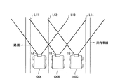
続いてステップS23において、撮像部13が得た撮像画像から白線部分(車線区分線部分)を抽出する。ここで、図4に示すように自車両が片側3車線の道路を走行している場合を例に挙げて説明する。この図4に示すように、道路は、左側から第1乃至第4白線LI1,LI2,LI3,LI4により区分されることで、片側3車線の道路として構成されている。このような道路を自車両が走行する場合、車線毎で得られる撮像画像は異なる。さらにその画像中から白線を抽出して構成される画像も、走行車線に応じて異なるものになる。
First, in step S21, the currently traveling road type (general road or highway) is acquired from the road information from the
Subsequently, in step S23, a white line portion (lane marking line portion) is extracted from the captured image obtained by the
すなわち、走行方向に向かって左側車線を自車両100Aが走行している場合、当該自車両100Aの撮像部13が得る撮像画像Pは、図5中(A)に示すように、主に第1、第2及び第3白線LI1,LI2,LI3により構成される特有の画像になる。また、中央車線を自車両100Bが走行している場合、当該自車両100Bの撮像部13が得る撮像画像Pは、図5中(B)に示すように、主に第1、第2、第3及び第4白線LI1,LI2,LI3,LI4により構成される特有の画像になる。また、走行方向に向かって右側車線を自車両100Cが走行している場合、当該自車両100Cの撮像部13が得る撮像画像Pは、図5中(C)に示すように、主に第2、第3及び第4白線LI2,LI3,LI4により構成される特有の画像になる。このように、走行車線に応じて画像中の白線の構成が異なる。
That is, when the
続いてステップS24において、自車両走行車線(自車両走行レーン)を判定する。具体的には、前記ステップS22及びステップS23で得た情報に基づいて自車両走行車線を判定する。すなわち、自車両が現在走行している道路の車線数と撮像部13により得た撮像画像(白線を抽出した画像)とに基づいて自車両走行車線を判定する。例えば、車線数及び走行車線に応じて得られる画像を予め画像データとしてもっていて、その予め用意している画像データと自車両が現在走行している道路の車線数及び撮像部13で得た現在の撮像画像(白線を抽出した画像)とを比較して自車両走行車線を判定する。
Subsequently, in step S24, the host vehicle travel lane (host vehicle travel lane) is determined. Specifically, the host vehicle travel lane is determined based on the information obtained in steps S22 and S23. In other words, the host vehicle travel lane is determined based on the number of lanes of the road on which the host vehicle is currently traveling and the captured image (image obtained by extracting the white line) obtained by the
続いてステップS25において、自車両が走行している車線からみた左右方向の安全度を判定する。具体的には、自車両が逸脱した場合に安全度が低い方向を情報として保持している。これにより、自車両が走行している車線からみて左方向が安全度が低い場合には、その方向を安全度が低い方向(以下、第1障害物等存在方向という。)Soutとして保持し(Sout=left)、自車両が走行している車線からみて右方向が安全度が低い場合には、その方向を第1障害物等存在方向Soutとして保持する(Sout=right)。例えば次のように判定する。 Subsequently, in step S25, the degree of safety in the left-right direction viewed from the lane in which the host vehicle is traveling is determined. Specifically, the direction in which the degree of safety is low when the host vehicle deviates is held as information. Thus, when the safety level is low in the left direction when viewed from the lane in which the host vehicle is traveling, the direction is held as a low safety level direction (hereinafter referred to as a first obstacle existence direction) Sout ( Sout = left) When the safety level is low in the right direction when viewed from the lane in which the host vehicle is traveling, the direction is held as the first obstacle existence direction Sout (Sout = right). For example, the determination is made as follows.
例えば前記図4において、左側車線を自車両100Aが走行している場合、当該左側車線の右方向に逸脱するときよりも、左側車線の左方向に逸脱したときの方が安全度は低い。これは、左側車線の左方向は路肩があり、その路肩には、壁、ガードレール、障害物或いは崖等がある可能性が高い。よって、左車線を自車両100Aが走行している場合、第1障害物等存在方向Soutが左方向であると判定する(Sout=left)。
For example, in FIG. 4, when the
また、中央車線を自車両100Bが走行している場合、どの方向に逸脱したとしても当該自車両100Bが未だ路内にあるので、現在の走行車線に対して左右どちらの方向でも安全度は同じになる。
また、右側車線を自車両100Cが走行している場合、左方向、すなわち隣車線に逸脱するときよりも、右方向、すなわち対向車線に逸脱したときの方が安全度が低くなる。よって、この場合、右側車線を自車両100Aが走行している場合、第1障害物等存在方向Soutが右方向であると判定する(Sout=right)。
In addition, when the
Further, when the
また、一般道路と高速道路とで比較した場合、一般道路では、路肩の幅が高速道路より狭く、また路肩に障害物が多く、また歩行者もいる。このため、一般道路において路肩側に逸脱することは、高速道路において路肩側に逸脱する場合よりも安全度が低くなる。
また、車線数で比較した場合、左方向が路肩になり、右方向が対向車線になる片側1車線のときがより安全度が低くなる。この場合には、左右両方向が第1障害物等存在方向Soutであると判定する(Sout=both)。
Moreover, when compared with ordinary roads and expressways, the width of shoulders on ordinary roads is narrower than that of expressways, there are many obstacles on the shoulders, and there are also pedestrians. For this reason, deviating to the shoulder side on a general road is less safe than deviating to the shoulder side on an expressway.
Further, when compared by the number of lanes, the safety degree is lower when the left side is the road shoulder and the right direction is one lane on the opposite lane. In this case, it is determined that the left and right directions are the first obstacle existence direction Sout (Sout = both).
なお、例えば片側1車線道路は中央分離帯やガードレール等がないことがほとんどであるので、当該片側1車線道路を走行している場合の撮像画像は、図5中(A)に示すようになる。すなわち、片側1車線道路を走行している場合の撮像画像は3車線道路の左側車線を走行して車両100Aの撮像部13が得る撮像画像と同じになる。よって、一般道路と高速道路とを走行することを前提としている場合、撮像画像だけでは前記第1障害物等存在方向を判定することはできない。このようなことから、ナビゲーション装置15から自車両が現在走行している道路の車線数を得て、現在走行している道路が片側1車線道路であるか片側3車線道路であるかを判別することで、片側1車線道路を走行している場合には、右方向についても安全度が低いことも判定できる。
Note that, for example, since one-sided one-lane roads generally do not have a median strip or guardrail, a captured image when traveling on the one-sided one-lane road is as shown in FIG. . That is, the captured image when traveling on a one-lane road is the same as the captured image obtained by the
以上の図3に示す処理手順により、図2に示すステップS3の走行環境の判定を行う。
続いてステップS4において、車線逸脱傾向の判定を行う。この判定の処理の処理手順は具体的には図6に示すようになる。
先ずステップS31において、逸脱予測時間Toutを算出する。具体的には、dxを前記横変位Xの変化量(単位時間当たりの変化量)とし、Lを車線幅とし、横変位Xを用いて、下記(2)式により逸脱予測時間Toutを算出する(X,dx,Lの値については図7を参照)。
The travel environment is determined in step S3 shown in FIG. 2 according to the processing procedure shown in FIG.
Subsequently, in step S4, a lane departure tendency is determined. Specifically, the processing procedure of this determination processing is as shown in FIG.
First, in step S31, a predicted departure time Tout is calculated. Specifically, the deviation predicted time Tout is calculated by the following equation (2) using dx as the change amount of the lateral displacement X (change amount per unit time), L as the lane width, and the lateral displacement X. (See FIG. 7 for values of X, dx, and L).
Tout=(L/2−X)/dx ・・・(2)
この(2)式によれば、車線中央(X=0)からXだけ横変位している車両100が、その位置から距離L/2だけ離れた外側位置領域(例えば路肩)に至るまでの逸脱予測時間Toutを求めることができる。
なお、車線幅Lについては、撮像部13が撮像画像を処理することで得ている。また、ナビゲーション装置15から車両の位置を得たり、ナビゲーション装置15の地図データから車線幅Lを得てもよい。
Tout = (L / 2−X) / dx (2)
According to the equation (2), the
Note that the lane width L is obtained by the
続いてステップS32において、逸脱判断フラグを設定する。具体的には、前記逸脱予測時間Toutと所定の第1逸脱判断しきい値Tsとを比較する。ここで、逸脱予測時間Toutが第1逸脱判断しきい値Ts未満の場合(Tout<Ts)、逸脱する(逸脱傾向あり)と判定するとともに、逸脱判断フラグFoutをONにする(Fout=ON)。また、逸脱予測時間Toutが第1逸脱判断しきい値Ts以上の場合(Tout≧Ts)、逸脱しない(逸脱傾向なし)と判定するとともに、逸脱判断フラグFoutをOFFにする(Fout=OFF)。 Subsequently, in step S32, a departure determination flag is set. Specifically, the predicted departure time Tout is compared with a predetermined first departure determination threshold value Ts. Here, if the predicted departure time Tout is less than the first departure determination threshold value Ts (Tout <Ts), it is determined that the departure (there is a departure tendency) and the departure determination flag Fout is turned on (Fout = ON). . If the predicted departure time Tout is equal to or greater than the first departure determination threshold value Ts (Tout ≧ Ts), it is determined that there is no departure (no departure tendency) and the departure determination flag Fout is turned off (Fout = OFF).
このステップS32の処理により、例えば自車両が車線中央から離れていき、逸脱予測時間Toutが第1逸脱判断しきい値Ts未満になったとき(Tout<Ts)、逸脱判断フラグFoutがONになる(Fout=ON)。また、自車両(Fout=ONの状態の自車両)が車線中央側に復帰していき、逸脱予測時間Toutが第1逸脱判断しきい値Ts以上になったとき(Tout≧Ts)、逸脱判断フラグFoutがOFFになる(Fout=OFF)。例えば、逸脱傾向がある場合に、後述する逸脱回避のための制動制御が実施されたり、或いは運転者自身が回避操作をすれば、逸脱判断フラグFoutがONからOFFになる。 By the process of step S32, for example, when the host vehicle moves away from the center of the lane and the predicted departure time Tout becomes less than the first departure determination threshold value Ts (Tout <Ts), the departure determination flag Fout is turned on. (Fout = ON). Further, when the own vehicle (the own vehicle in the state where Fout = ON) returns to the lane center side and the estimated departure time Tout becomes equal to or longer than the first departure determination threshold value Ts (Tout ≧ Ts), the departure determination. The flag Fout is turned off (Fout = OFF). For example, when there is a tendency to deviate, if the braking control for avoiding deviation described later is performed, or if the driver himself performs an avoidance operation, the deviation determination flag Fout is changed from ON to OFF.
なお、第1逸脱判断しきい値Tsは変更可能である。すなわち例えば、前記ステップS3で得た安全度に基づいて第1逸脱判断しきい値Tsを設定することもできる。
続いてステップS33において、横変位Xに基づいて逸脱方向Doutを判定する。具体的には、車線中央から左方向に横変位している場合、その方向を逸脱方向Doutにし(Dout=left)、車線中央から右方向に横変位している場合、その方向を逸脱方向Doutにする(Dout=right)。
The first departure determination threshold value Ts can be changed. That is, for example, the first departure determination threshold value Ts can be set based on the safety degree obtained in step S3.
Subsequently, in step S33, the departure direction Dout is determined based on the lateral displacement X. Specifically, when the vehicle is laterally displaced from the center of the lane to the left, the direction is set as the departure direction Dout (Dout = left), and when the vehicle is laterally displaced from the center of the lane to the right, the direction is changed to the departure direction Dout. (Dout = right).
以上のようにステップS4において車線逸脱傾向を判定する。
続いてステップS5において、運転者の車線変更の意図を判定する。具体的には、前記ステップS1で得た方向スイッチ信号及び操舵角δに基づいて、次のように運転者の車線変更の意図を判定する。
方向スイッチ信号が示す方向(ウインカ点灯側)と、前記ステップS4で得た逸脱方向Doutが示す方向とが同じである場合、運転者が意識的に車線変更していると判定し、逸脱判断フラグFoutをOFFに変更する(Fout=OFF)。すなわち、逸脱しないとの判定結果に変更する。
As described above, the lane departure tendency is determined in step S4.
Subsequently, in step S5, the driver's intention to change lanes is determined. Specifically, based on the direction switch signal and the steering angle δ obtained in step S1, the driver's intention to change lanes is determined as follows.
If the direction indicated by the direction switch signal (the blinker lighting side) is the same as the direction indicated by the departure direction Dout obtained in step S4, it is determined that the driver has intentionally changed the lane, and the departure determination flag Fout is changed to OFF (Fout = OFF). That is, it is changed to a determination result that there is no deviation.
また、方向スイッチ信号が示す方向(ウインカ点灯側)と、前記ステップS4で得た逸脱方向Doutが示す方向とが異なる場合、逸脱判断フラグFoutを維持し、逸脱判断フラグFoutをONのままにする(Fout=ON)。すなわち、逸脱するとの判定結果を維持する。
また、方向指示スイッチ20が操作されていない場合には、操舵角δに基づいて運転者の車線変更の意図を判定する。すなわち、運転者が逸脱方向に操舵している場合において、その操舵角δ及びその操舵角の変化量(単位時間当たりの変化量)Δδが設定値以上のときには、運転者が意識的に車線変更していると判定し、逸脱判断フラグFoutをOFFに変更する(Fout=OFF)。
When the direction indicated by the direction switch signal (the blinker lighting side) is different from the direction indicated by the departure direction Dout obtained in step S4, the departure determination flag Fout is maintained and the departure determination flag Fout is kept ON. (Fout = ON). That is, the determination result that deviates is maintained.
When the
続いてステップS6において、逸脱回避のための制御方法を決定する。具体的には、逸脱の警報や逸脱回避の制動制御を行うか否か、さらには逸脱回避の制動制御を行う場合にその制動制御方法を決定する。
例えば、前記ステップS5で得た逸脱判断フラグFoutのON及びOFFの状態に応じて逸脱の警報を作動させる。例えば、逸脱判断フラグFoutがON(Tout<Ts)になっているが、運転者による操舵操作等により車線逸脱しないと判断できるときには、逸脱の警報を実施する。例えば、音や表示等により警報を行う。
Subsequently, in step S6, a control method for avoiding deviation is determined. Specifically, whether or not to perform a departure warning or braking control for avoiding departure, and further, when performing braking control for avoiding departure, the braking control method is determined.
For example, a departure warning is activated according to the ON / OFF state of the departure determination flag Fout obtained in step S5. For example, when the departure determination flag Fout is ON (Tout <Ts), but it can be determined that the lane does not deviate due to a steering operation by the driver, a departure warning is performed. For example, an alarm is given by sound or display.
ここで、逸脱判断フラグFoutがON(Tout<Ts)になっているが、運転者による操舵操作等により車線逸脱しないと判断できる場合とは、例えば、運転者自身が自車両の逸脱傾向に気づいて回避操作をしているが、未だ逸脱判断フラグFout自体がON(Tout<Ts)になっているような場合である。
また、逸脱判断フラグFoutがONの場合(Tout<Ts)において、前記ステップS3で得た第1障害物等存在方向Sout及びステップS4で得た逸脱方向Doutに基づいて逸脱回避の制動制御方法も決定する。これについては、後で詳述する。
Here, the departure determination flag Fout is ON (Tout <Ts), but the case where it can be determined that the lane does not deviate due to the steering operation by the driver, for example, the driver himself notices the departure tendency of the own vehicle. In this case, the departure determination flag Fout itself is still ON (Tout <Ts).
Further, when the departure determination flag Fout is ON (Tout <Ts), a braking control method for avoiding departure based on the first obstacle existence direction Sout obtained in step S3 and the departure direction Dout obtained in step S4 is also provided. decide. This will be described in detail later.
続いてステップS7において、自車両に発生させる目標ヨーモーメントを算出する。この目標ヨーモーメントは、逸脱回避のために自車両に付与するヨーモーメントである。
具体的には、前記ステップS1で得た横変位Xと前記変化量dxとに基づいて、下記(3)式により目標ヨーモーメントMsを算出する。
Ms=K1・X+K2・dx ・・・(3)
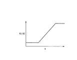
ここで、K1,K2は車速Vに応じて変動するゲインである。例えば、図8はその例を示す。この図8に示すように、例えばゲインK1,K2は、低速域で小さい値になり、車速Vがある値になると、車速Vの増加に対応して大きくなり、その後ある車速Vに達すると一定値になる。
Subsequently, in step S7, a target yaw moment to be generated in the host vehicle is calculated. This target yaw moment is a yaw moment to be given to the host vehicle in order to avoid departure.
Specifically, the target yaw moment Ms is calculated by the following equation (3) based on the lateral displacement X and the change dx obtained in step S1.
Ms = K1 · X + K2 · dx (3)
Here, K1 and K2 are gains that vary according to the vehicle speed V. For example, FIG. 8 shows an example. As shown in FIG. 8, for example, the gains K1 and K2 are small values in the low speed range. When the vehicle speed V reaches a certain value, the gains K1 and K2 increase in response to the increase in the vehicle speed V, and then constant when the vehicle speed V reaches a certain value. Value.
続いてステップS8において、逸脱回避用の減速度を算出する。すなわち、自車両を減速させる目的として左右両輪に与える制動力を算出する。ここでは、そのような制動力を左右両輪に与える目標制動液圧Pgf,Pgrとして算出する。前輪用の目標制動液圧Pgfについては下記(4)式により算出する。
Pgf=Kgv・V+Kgx・dx ・・・(4)
ここで、Kgv,Kgxはそれぞれ、車速V及び横変化量dxに基づいて設定する、制動力を制動液圧に換算するための換算係数である。例えば、図9はその例を示す。この図9に示すように、例えば換算係数Kgv,Kgxは、低速域で大きい値になり、車速Vがある値になると、車速Vの増加に対応して小さくなり、その後ある車速Vに達すると一定値になる。
Subsequently, in step S8, a deceleration for avoiding deviation is calculated. That is, the braking force applied to the left and right wheels for the purpose of decelerating the host vehicle is calculated. Here, the target braking fluid pressures Pgf and Pgr that give such braking force to both the left and right wheels are calculated. The target braking hydraulic pressure Pgf for the front wheels is calculated by the following equation (4).
Pgf = Kgv · V + Kgx · dx (4)
Here, Kgv and Kgx are conversion coefficients that are set based on the vehicle speed V and the lateral change amount dx, respectively, for converting the braking force into the braking hydraulic pressure. For example, FIG. 9 shows an example. As shown in FIG. 9, for example, the conversion coefficients Kgv and Kgx have large values in the low speed range, and when the vehicle speed V reaches a certain value, the conversion coefficients Kgv and Kgx decrease with the increase in the vehicle speed V and then reach a certain vehicle speed V. It becomes a constant value.
そして、前輪用の目標制動液圧Pgfに基づいて、前後配分を考慮した後輪用の目標制動液圧Pgrを算出する。
このようにステップS8において、逸脱回避用の減速度(具体的には目標制動液圧Pgf,Pgr)を得る。
続いてステップS9において、逸脱判断フラグFoutがONか否かを判定する。ここで、逸脱判断フラグFoutがONの場合、ステップS10に進み、逸脱判断フラグFoutがOFFの場合、ステップS12に進む。
Then, based on the target braking hydraulic pressure Pgf for the front wheels, the target braking hydraulic pressure Pgr for the rear wheels considering the front-rear distribution is calculated.
Thus, in step S8, deceleration for avoiding deviation (specifically, target braking hydraulic pressures Pgf, Pgr) is obtained.
Subsequently, in step S9, it is determined whether or not the departure determination flag Fout is ON. If the departure determination flag Fout is ON, the process proceeds to step S10. If the departure determination flag Fout is OFF, the process proceeds to step S12.
ステップS10では、舵角方向を判定する。具体的には、舵角方向と逸脱回避方向とが一致しているか否かを判定する。ここで、逸脱回避方向とは、前記ステップS4で得た逸脱方向への逸脱を回避するための方向であり、すなわち反逸脱方向である。また、舵角方向は、前記ステップS1で得た操舵角δに基づいて得る。
ここで、舵角方向と逸脱回避方向とが一致している場合、前記ステップS12に進み、舵角方向と逸脱回避方向とが一致していない場合、ステップS11に進む。
In step S10, the steering angle direction is determined. Specifically, it is determined whether or not the rudder angle direction and the departure avoidance direction match. Here, the departure avoidance direction is a direction for avoiding the departure in the departure direction obtained in step S4, that is, the counter departure direction. The steering angle direction is obtained based on the steering angle δ obtained in step S1.
If the rudder angle direction and the departure avoidance direction match, the process proceeds to step S12. If the rudder angle direction and the departure avoidance direction do not coincide, the process proceeds to step S11.
ステップS11及びステップS12では、各車輪の目標制動液圧を算出する。
先ずステップS12では、逸脱判断フラグFoutがOFFの場合(Fout=OFF)、すなわち逸脱しないとの判定結果を得た場合として、次のように目標制動液圧を算出する。
下記(5)式及び(6)式に示すように、各車輪の目標制動液圧Psi(i=fl,fr,rl,rr)をマスタシリンダ液圧Pmf,Pmrにする。
Psfl=Psfr=Pmf ・・・(5)
Psrl=Psrr=Pmr ・・・(6)
ここで、Pmfは前輪用のマスタシリンダ液圧である。また、Pmrは後輪用のマスタシリンダ液圧であり、前後配分を考慮して前輪用のマスタシリンダ液圧Pmfに基づいて算出した値になる。
In step S11 and step S12, the target brake hydraulic pressure of each wheel is calculated.
First, in step S12, the target brake hydraulic pressure is calculated as follows when the departure determination flag Fout is OFF (Fout = OFF), that is, when the determination result that there is no departure is obtained.
As shown in the following equations (5) and (6), the target brake hydraulic pressure Psi (i = fl, fr, rl, rr) of each wheel is set to the master cylinder hydraulic pressures Pmf, Pmr.
Psfl = Psfr = Pmf (5)
Psrl = Psrr = Pmr (6)
Here, Pmf is the master cylinder hydraulic pressure for the front wheels. Pmr is a master cylinder hydraulic pressure for the rear wheels, and is a value calculated based on the master cylinder hydraulic pressure Pmf for the front wheels in consideration of the front-rear distribution.
一方、ステップS11では、逸脱判断フラグFoutがONの場合(Fout=ON)、すなわち逸脱するとの判定結果を得た場合として、次のように目標制動液圧を算出する。
先ず前記目標ヨーモーメントMsに基づいて、前輪目標制動液圧差ΔPsf及び後輪目標制動液圧差ΔPsrを算出する。具体的には、下記(7)式〜(10)式により目標制動液圧差ΔPsf,ΔPsrを算出する。
Ms<Ms1の場合
ΔPsf=0 ・・・(7)
ΔPsr=2・Kbr・Ms/T ・・・(8)
Ms≧Ms1の場合
ΔPsf=2・Kbf・(Ms−Ms1)/T ・・・(9)
ΔPsr=2・Kbr・Ms1/T ・・・(10)
ここで、Ms1は設定用しきい値を示す。また、Tはトレッドを示す。なお、このトレッドTは、簡単のため前後で同じ値にする。また、Kbf,Kbrは、制動力を制動液圧に換算する場合の前輪及び後輪についての換算係数であり、ブレーキ諸元により定まる。
On the other hand, in step S11, when the departure determination flag Fout is ON (Fout = ON), that is, when a determination result indicating departure is obtained, the target braking hydraulic pressure is calculated as follows.
First, based on the target yaw moment Ms, a front wheel target braking hydraulic pressure difference ΔPsf and a rear wheel target braking hydraulic pressure difference ΔPsr are calculated. Specifically, the target braking hydraulic pressure differences ΔPsf and ΔPsr are calculated by the following equations (7) to (10).
In the case of Ms <Ms1, ΔPsf = 0 (7)
ΔPsr = 2 · Kbr · Ms / T (8)
When Ms ≧ Ms1 ΔPsf = 2 · Kbf · (Ms−Ms1) / T (9)
ΔPsr = 2 · Kbr · Ms1 / T (10)
Here, Ms1 represents a setting threshold value. T represents a tread. This tread T is set to the same value before and after for simplicity. Kbf and Kbr are conversion coefficients for the front wheels and the rear wheels when the braking force is converted into the braking hydraulic pressure, and are determined by the brake specifications.
このように、目標ヨーモーメントMsの大きさに応じて車輪に与える制動力を配分している。すなわち、目標ヨーモーメントMsが設定用しきい値Ms1未満のときには、前輪目標制動液圧差ΔPsfを0として、後輪目標制動液圧差ΔPsrに所定値を与えて、左右後輪で制動力差を発生させ、また、目標ヨーモーメントMsが設定用しきい値Ms1以上のときには、各目標制動液圧差ΔPsr,ΔPsrに所定値を与え、前後左右輪で制動力差を発生させる。 Thus, the braking force applied to the wheels is distributed according to the magnitude of the target yaw moment Ms. That is, when the target yaw moment Ms is less than the setting threshold value Ms1, the front wheel target braking hydraulic pressure difference ΔPsf is set to 0, a predetermined value is given to the rear wheel target braking hydraulic pressure difference ΔPsr, and a braking force difference is generated between the left and right rear wheels. Further, when the target yaw moment Ms is equal to or larger than the setting threshold value Ms1, a predetermined value is given to each target braking hydraulic pressure difference ΔPsr, ΔPsr, and a braking force difference is generated between the front, rear, left and right wheels.
そして、逸脱判断フラグFoutがONの場合(Fout=ON)には、以上のように算出した目標制動液圧差ΔPsf,ΔPsr及び減速用の目標制動液圧Pgf,Pgrを用いて最終的な各車輪の目標制動液圧Psi(i=fl,fr,rl,rr)を算出する。具体的には、前記ステップS6で決定した制動制御方法に基づいて最終的な各車輪の目標制動液圧Psi(i=fl,fr,rl,rr)を算出する。 When the departure determination flag Fout is ON (Fout = ON), the final wheels are calculated using the target braking fluid pressure differences ΔPsf and ΔPsr and the deceleration target braking fluid pressures Pgf and Pgr calculated as described above. Target brake hydraulic pressure Psi (i = fl, fr, rl, rr) is calculated. Specifically, the final target brake hydraulic pressure Psi (i = fl, fr, rl, rr) of each wheel is calculated based on the braking control method determined in step S6.
ここで、前記ステップS6で決定する制動制御方法を説明する。
前記ステップS6では、逸脱判断フラグFoutがONの場合に作動させる制動制御を前記第1障害物等存在方向Soutと前記逸脱方向Doutに基づいて決定しており、ここでは第1障害物等存在方向Soutと逸脱方向Doutとの状態で場合分け(第1のケース〜第3のケース)してその制動制御方法を説明する。
Here, the braking control method determined in step S6 will be described.
In step S6, the braking control to be activated when the departure determination flag Fout is ON is determined based on the first obstacle existence direction Sout and the departure direction Dout. Here, the first obstacle existence direction is determined. The braking control method will be described for each of the cases of Sout and departure direction Dout (first case to third case).
(第1のケース) 第1障害物等存在方向Soutと逸脱方向Doutとが一致していない場合、逸脱判断フラグFoutがOFFになるまで、逸脱を回避するためのヨーモーメントが車両に付与されるように制動制御(以下、逸脱回避用ヨー制御という。)をする。
ここで、逸脱を回避するために車両に付与するヨーモーメントの大きさが前記目標ヨーモーメントMsになる。そして、車両へのヨーモーメントの付与は、左右の車輪に与える制動力に差をつけることで行う。具体的には、前述したように、目標ヨーモーメントMsが設定用しきい値Ms1未満のときには、左右後輪で制動力差を発生させて、車両に当該目標ヨーモーメントMsを付与し、また、目標ヨーモーメントMsが設定用しきい値Ms1以上のときには、前後左右輪で制動力差を発生させて、車両に当該目標ヨーモーメントMsを付与する。
また、逸脱判断フラグFoutがONからOFFになる場合とは、逸脱傾向がある場合に、逸脱回避のための制動制御が実施されたり、或いは運転者自身が回避操作をしたようなときである。
(First Case) When the first obstacle existence direction Sout and the departure direction Dout do not coincide with each other, a yaw moment for avoiding departure is applied to the vehicle until the departure determination flag Fout is turned off. Thus, braking control (hereinafter referred to as deviation avoidance yaw control) is performed.
Here, the magnitude of the yaw moment applied to the vehicle in order to avoid the departure is the target yaw moment Ms. The yaw moment is applied to the vehicle by making a difference in the braking force applied to the left and right wheels. Specifically, as described above, when the target yaw moment Ms is less than the setting threshold value Ms1, a braking force difference is generated between the left and right rear wheels to apply the target yaw moment Ms to the vehicle. When the target yaw moment Ms is equal to or greater than the setting threshold value Ms1, a braking force difference is generated between the front, rear, left and right wheels, and the target yaw moment Ms is applied to the vehicle.
Further, the case where the departure determination flag Fout is changed from ON to OFF is when braking control for avoiding departure is performed or the driver himself performs an avoidance operation when there is a departure tendency.
(第2のケース) 第1障害物等存在方向Soutと逸脱方向Doutとが一致し、かつ前記ステップS3で得た道路種別Rが一般道路の場合、逸脱判断フラグFoutがOFFになるまで、逸脱回避用ヨー制御を行う。
さらに、前記第1逸脱判断しきい値Ts未満の第2逸脱判断しきい値Tr(Ts>Tr>0)を定義して、この第2逸脱判断しきい値Trよりも逸脱予測時間Toutが小さくなったときに、逸脱回避用ヨー制御に加えて、車両を減速させるための制動制御(以下、逸脱回避用減速制御という。)を行う。この逸脱回避用減速制御は、左右両車輪に同程度の制動力を与えて行う。
(Second Case) When the first obstacle existence direction Sout matches the departure direction Dout and the road type R obtained in Step S3 is a general road, the departure is continued until the departure determination flag Fout is turned OFF. Perform avoidance yaw control.
Further, a second departure judgment threshold value Tr (Ts>Tr> 0) less than the first departure judgment threshold value Ts is defined, and the predicted departure time Tout is smaller than the second departure judgment threshold value Tr. When this happens, in addition to the departure avoidance yaw control, braking control for decelerating the vehicle (hereinafter referred to as departure avoidance deceleration control) is performed. This departure avoidance deceleration control is performed by applying the same level of braking force to the left and right wheels.
(第3のケース) 第1障害物等存在方向Soutと逸脱方向Doutとが一致し、かつ前記ステップS3で得た道路種別Rが高速道路の場合、逸脱判断フラグFoutがOFFになるまで、逸脱回避用ヨー制御を行う。
さらに、この場合、逸脱予測時間Toutが0になったときに、逸脱回避用ヨー制御に加えて、逸脱回避用減速制御を行う。
なお、この第3のケースの場合において、前記第2のケースと同様に、第2逸脱判断しきい値Trよりも逸脱予測時間Toutが小さくなったときにも、車両を減速させるための制動制御(逸脱回避用減速制御)を行ってもよい。この場合、例えば、逸脱予測時間Toutが0になったときに、逸脱回避用減速制御による自車両の減速度をさらに大きくする。これにより、第2逸脱判断しきい値Trよりも逸脱予測時間Toutが小さくなったとき、さらには逸脱予測時間Toutが0になったときに、逸脱回避用減速制御が作動するようになる。そして、この場合、逸脱予測時間Toutが0になったときに、より自車両の減速度が大きくなる。
(Third Case) When the first obstacle existence direction Sout and the departure direction Dout coincide with each other and the road type R obtained in step S3 is a highway, the departure is continued until the departure determination flag Fout is turned off. Perform avoidance yaw control.
Further, in this case, when the predicted departure time Tout becomes 0, the departure avoidance deceleration control is performed in addition to the departure avoidance yaw control.
In the case of the third case, as in the case of the second case, the braking control for decelerating the vehicle also when the predicted departure time Tout becomes smaller than the second departure determination threshold value Tr. (Deceleration avoidance deceleration control) may be performed. In this case, for example, when the estimated departure time Tout becomes 0, the deceleration of the host vehicle by the departure avoidance deceleration control is further increased. Thereby, when the predicted departure time Tout becomes smaller than the second departure determination threshold value Tr, and further when the predicted departure time Tout becomes 0, the departure avoidance deceleration control is activated. In this case, when the estimated departure time Tout becomes 0, the deceleration of the host vehicle becomes larger.
前記ステップS6では、このように第1障害物等存在方向Soutと逸脱方向Doutとの状態に応じて種々の制動制御方法を決定している。すなわち、第1障害物等存在方向Soutと逸脱方向Doutとの状態に応じて、逸脱回避用ヨー制御のみ、或いは逸脱回避用ヨー制御と逸脱回避用減速制御との組み合わせとして、逸脱回避のための制動制御方法を決定している。 In step S6, various braking control methods are determined according to the state of the first obstacle etc. existence direction Sout and the departure direction Dout. In other words, depending on the state of the first obstacle etc. existence direction Sout and the departure direction Dout, only the departure avoidance yaw control, or the combination of the departure avoidance yaw control and the departure avoidance deceleration control, The braking control method is determined.
そして、ステップS11では、各車輪の目標制動液圧Psi(i=fl,fr,rl,rr)をこのような各種制動制御方法に対応して算出する。
例えば、前記第1のケース〜第3のケースの場合における逸脱回避用ヨー制御では、下記(11)式により各車輪の目標制動液圧Psi(i=fl,fr,rl,rr)を算出する。
Psfl=Pmf
Psfr=Pmf+ΔPsf
Psrl=Pmr
Psrr=Pmr+ΔPsr
・・・(11)
In step S11, the target braking fluid pressure Psi (i = fl, fr, rl, rr) of each wheel is calculated corresponding to such various braking control methods.
For example, in the deviation avoidance yaw control in the first to third cases, the target braking hydraulic pressure Psi (i = fl, fr, rl, rr) of each wheel is calculated by the following equation (11). .
Psfl = Pmf
Psfr = Pmf + ΔPsf
Psrl = Pmr
Psrr = Pmr + ΔPsr
(11)
また、前記第2及び第3のケースの場合では、逸脱回避用ヨー制御と逸脱回避用減速制御とを行うことになるが、この場合、下記(12)式により各車輪の目標制動液圧Psi(i=fl,fr,rl,rr)を算出する。
Psfl=Pmf+Pgf/2
Psfr=Pmf+ΔPsf+Pgf/2
Psrl=Pmr+Pgr/2
Psrr=Pmr+ΔPsr+Pgr/2
・・・(12)
また、この(11)式及び(12)式が示すように、運転者による減速操作、すなわちマスタシリンダ液圧Pmf,Pmrを考慮して各車輪の目標制動液圧Psi(i=fl,fr,rl,rr)を算出している。
In the case of the second and third cases, deviation avoidance yaw control and departure avoidance deceleration control are performed. In this case, the target braking hydraulic pressure Psi of each wheel is expressed by the following equation (12). (I = fl, fr, rl, rr) is calculated.
Psfl = Pmf + Pgf / 2
Psfr = Pmf + ΔPsf + Pgf / 2
Psrl = Pmr + Pgr / 2
Psrr = Pmr + ΔPsr + Pgr / 2
(12)
Further, as shown by the equations (11) and (12), the deceleration operation by the driver, that is, the target brake fluid pressure Psi (i = fl, fr, rl, rr) is calculated.
以上がステップS11の処理になる。このステップS11又は前記ステップS12により、逸脱判断フラグFoutの状態に基づいて各車輪の目標制動液圧Psi(i=fl,fr,rl,rr)を算出している。そして、逸脱判断フラグFoutがONの場合(ステップS12)には、前記ステップS6で第1障害物等存在方向Soutと逸脱方向Doutとの状態に応じて決定した種々の制動制御方法に対応して各車輪の目標制動液圧Psi(i=fl,fr,rl,rr)を算出している。 The above is the process of step S11. In step S11 or step S12, the target brake hydraulic pressure Psi (i = fl, fr, rl, rr) of each wheel is calculated based on the state of the departure determination flag Fout. When the departure determination flag Fout is ON (step S12), it corresponds to various braking control methods determined in accordance with the state of the first obstacle etc. existence direction Sout and the departure direction Dout in step S6. The target braking fluid pressure Psi (i = fl, fr, rl, rr) of each wheel is calculated.
以上が、制駆動力コントロールユニット8による演算処理である。そして、制駆動力コントロールユニット8は、前記ステップS11又はステップS12で算出した各車輪の目標制動液圧Psi(i=fl,fr,rl,rr)を制動流体圧指令値として、制動流体圧制御部7に出力する。
以上のような車線逸脱防止装置は概略として次のように動作する。
先ず、各センサやコントローラ、コントロールユニットから各種データを読み込む(前記ステップS1)。続いて車速Vを算出する(前記ステップS2)。
続いて、走行環境を判定して、安全度が低い方向(第1障害物等存在方向Sout)を決定する(前記ステップS3、図3)。例えば、前記図4において左側車線を自車両100Aが走行している場合、第1障害物等存在方向Soutを左方向にする、といったようにである。
The above is the calculation processing by the braking / driving force control unit 8. Then, the braking / driving force control unit 8 uses the target braking fluid pressure Psi (i = fl, fr, rl, rr) calculated in step S11 or step S12 as a braking fluid pressure command value to control the braking fluid pressure. Output to unit 7.
The lane departure prevention apparatus as described above generally operates as follows.
First, various data are read from each sensor, controller, and control unit (step S1). Subsequently, the vehicle speed V is calculated (step S2).
Subsequently, the traveling environment is determined, and the direction in which the degree of safety is low (the first obstacle etc. existence direction Sout) is determined (step S3, FIG. 3). For example, when the
また、逸脱予測時間Toutに基づいて逸脱判断フラグFoutを設定するとともに、横変位Xに基づいて逸脱方向Doutを判定する(前記ステップS4、図7)。
さらに、そのようにして得た逸脱方向Doutと方向スイッチ信号が示す方向(ウインカ点灯側)とに基づいて運転者の車線変更の意図を判定する(前記ステップS5)。
例えば、方向スイッチ信号が示す方向(ウインカ点灯側)と逸脱方向Doutが示す方向とが同じである場合、運転者が意識的に車線変更していると判定する。この場合、逸脱判断フラグFoutをOFFに変更する。
Further, the departure determination flag Fout is set based on the estimated departure time Tout, and the departure direction Dout is determined based on the lateral displacement X (step S4, FIG. 7).
Further, the driver's intention to change the lane is determined based on the departure direction Dout thus obtained and the direction indicated by the direction switch signal (the blinker lighting side) (step S5).
For example, when the direction indicated by the direction switch signal (the blinker lighting side) and the direction indicated by the departure direction Dout are the same, it is determined that the driver has intentionally changed the lane. In this case, the departure determination flag Fout is changed to OFF.
また、方向スイッチ信号が示す方向(ウインカ点灯側)と逸脱方向Doutが示す方向とが異なる場合に、逸脱判断フラグFoutがONにされている場合には、それを維持する。これは例えば、方向スイッチ信号が示す方向(ウインカ点灯側)と逸脱方向Doutが示す方向とが異なる場合には、車両の逸脱挙動が運転者による車線変更等の運転者の意思による車両挙動でないと考えることができるので、逸脱判断フラグFoutがONにされている場合には、それを維持する。 In addition, when the direction indicated by the direction switch signal (the blinker lighting side) is different from the direction indicated by the departure direction Dout, the departure determination flag Fout is maintained when it is ON. For example, if the direction indicated by the direction switch signal (the blinker lighting side) is different from the direction indicated by the departure direction Dout, the departure behavior of the vehicle is not the vehicle behavior due to the driver's intention such as a lane change by the driver. Since it can be considered, if the departure determination flag Fout is ON, it is maintained.
そして、前記逸脱判断フラグFout、第1障害物等存在方向Sout及び逸脱方向Doutに基づいて逸脱回避のための警報開始の有無、逸脱回避のための制動制御の有無、逸脱回避のための制動制御を実施する場合のその方法を決定する(前記ステップS6)。
さらに、横変位Xと前記変化量dxとに基づいて目標ヨーモーメントMsを算出し(前記ステップS7)、また、逸脱回避用の減速度を算出する(前記ステップS8)。
そして、前記逸脱判断フラグFout、舵角方向及び逸脱回避方向に基づいて各車輪の目標制動液圧Psi(i=fl,fr,rl,rr)を算出している(ステップS9〜ステップS12)。
Based on the departure determination flag Fout, the first obstacle existence direction Sout, and the departure direction Dout, the presence or absence of an alarm for avoiding departure, the presence or absence of braking control for avoiding departure, and the braking control for avoiding departure Is determined (step S6).
Further, the target yaw moment Ms is calculated based on the lateral displacement X and the change amount dx (step S7), and the deceleration for avoiding deviation is calculated (step S8).
Based on the departure determination flag Fout, the steering angle direction, and the departure avoidance direction, the target braking fluid pressure Psi (i = fl, fr, rl, rr) of each wheel is calculated (steps S9 to S12).
具体的には、逸脱判断フラグFoutがOFFの場合、または逸脱判断フラグFoutがONでも舵角方向と逸脱回避方向とが一致している場合、各車輪の目標制動液圧Psi(i=fl,fr,rl,rr)をマスタシリンダ液圧Pmf,Pmrにしている(前記ステップS9、ステップS10、ステップS12)。また、逸脱判断フラグFoutがONで、かつ舵角方向と逸脱回避方向とが不一致の場合、前記ステップS6で第1障害物等存在方向Sout及び逸脱方向Doutに基づいて決定した制動制御方法を実現するための各車輪の目標制動液圧Psi(i=fl,fr,rl,rr)を算出している(前記ステップS9〜ステップS11)。 Specifically, when the departure determination flag Fout is OFF, or when the departure determination flag Fout is ON, the steering angle direction and the departure avoidance direction coincide with each other, the target brake hydraulic pressure Psi (i = fl, fr, rl, rr) are set to the master cylinder hydraulic pressures Pmf, Pmr (steps S9, S10, S12). Further, when the departure determination flag Fout is ON and the steering angle direction and the departure avoidance direction do not coincide with each other, the braking control method determined based on the first obstacle existence direction Sout and the departure direction Dout in step S6 is realized. The target braking fluid pressure Psi (i = fl, fr, rl, rr) for each wheel is calculated (steps S9 to S11).
そして、このように各条件に応じて算出した目標制動液圧Psi(i=fl,fr,rl,rr)を制動流体圧指令値として制動流体圧制御部7に出力している。制動流体圧制御部7では、制動流体圧指令値に基づいて、各ホイールシリンダ6FL〜6RRの制動流体圧を個別に制御する。これにより、逸脱傾向にある場合には、その走行環境に応じて所定の車両挙動を示すようになる。
ここで、前記第1のケース〜第3ケースの場合において、制動制御を行った場合の車両挙動を図10及び図11を用いて説明する。
The target brake fluid pressure Psi (i = fl, fr, rl, rr) calculated according to each condition is output to the brake fluid pressure controller 7 as a brake fluid pressure command value. The braking fluid pressure control unit 7 individually controls the braking fluid pressures of the wheel cylinders 6FL to 6RR based on the braking fluid pressure command value. As a result, when the vehicle tends to deviate, a predetermined vehicle behavior is exhibited according to the traveling environment.
Here, in the case of the first case to the third case, the vehicle behavior when the braking control is performed will be described with reference to FIGS. 10 and 11.
第2のケースとは、前述したように、第1障害物等存在方向Soutと逸脱方向Doutとが一致し、かつ道路種別Rが一般道路の場合である。すなわち、図10に示すように、左側が路肩Aになり、右側が対向車線(中央車線LI5側)になるような片側1車線を自車両100が走行している場合において、当該自車両100(図10中最上位置の自車両100)が左方向或いは当該自車両(図10中中間位置の自車両100)が右方向に逸脱する傾向にある場合である。
As described above, the second case is a case where the first obstacle existence direction Sout matches the departure direction Dout and the road type R is a general road. That is, as shown in FIG. 10, when the
この場合には逸脱回避用ヨー制御を行う。さらに、第2逸脱判断しきい値Trよりも逸脱予測時間Toutが小さくなったとき、逸脱回避用ヨー制御に加えて、逸脱回避用減速制御を行う。これにより、自車両は逸脱を回避する。一方、運転者は、この車両の逸脱回避動作を横方向の加速度或いは走行方向の減速度として感じ、自車両が逸脱傾向にあることを知ることができる。 In this case, deviation avoidance yaw control is performed. Further, when the predicted departure time Tout becomes shorter than the second departure determination threshold Tr, departure avoidance deceleration control is performed in addition to departure avoidance yaw control. Thereby, the own vehicle avoids deviation. On the other hand, the driver can feel the departure avoidance operation of the vehicle as the acceleration in the lateral direction or the deceleration in the traveling direction, and can know that the own vehicle tends to depart.
また、第3のケースとは、前述したように、第1障害物等存在方向Soutと逸脱方向Doutとが一致し、かつ道路種別Rが高速道路の場合である。すなわち、図11に示すように、3車線道路において、左側車線を走行している自車両100A(図11中最上位置の自車両100A)が左方向に逸脱する傾向がある場合である。或いは、図11に示すように、3車線道路において、右側車線を走行している自車両100C(図11中中間位置の自車両100C)が右方向に逸脱する傾向がある場合である。
Further, as described above, the third case is a case where the first obstacle existence direction Sout matches the departure direction Dout and the road type R is a highway. That is, as shown in FIG. 11, in the three-lane road, the
この場合には逸脱回避用ヨー制御を行う。これにより自車両は逸脱を回避できる。さらに、逸脱予測時間Toutが0になったとき、すなわち自車両が走行車線を逸脱したと判断したときには、逸脱回避用ヨー制御に加えて、逸脱回避用減速制御を行う。
なお、図10及び図11中、黒塗りしている車輪は、液圧を発生させて制動力が与えられている車輪を示す。すなわち、左右車輪のうちのいずれか一方が黒塗りの車輪の場合、左右車輪で液圧或いは制動力に差がある。この場合、車両にヨーモーメントが付与されることを示す。また、左右車輪が黒塗りの車輪の場合でも、その液圧値に差があるときもあり、この場合には、車両にヨーモーメントが付与されつつ、同時に当該車両が減速制御されていることを示す。このような関係は以降の図面でも同様である。
In this case, deviation avoidance yaw control is performed. Thereby, the own vehicle can avoid deviation. Further, when the predicted departure time Tout becomes 0, that is, when it is determined that the host vehicle has deviated from the traveling lane, the departure avoidance deceleration control is performed in addition to the departure avoidance yaw control.
In FIG. 10 and FIG. 11, the black wheels indicate wheels that generate hydraulic pressure and are given braking force. That is, when either one of the left and right wheels is a black wheel, there is a difference in hydraulic pressure or braking force between the left and right wheels. In this case, a yaw moment is given to the vehicle. Even if the left and right wheels are black wheels, there may be a difference in the hydraulic pressure values. In this case, it is confirmed that the vehicle is being subjected to deceleration control while a yaw moment is applied to the vehicle. Show. This relationship is the same in subsequent drawings.
また、第1のケースとは、前述したように、第1障害物等存在方向Soutと逸脱方向Doutとが一致していない場合である。すなわち、図11に示すように、3車線道路において、左側車線を走行している自車両100A(図11中中間位置の自車両100A)が右方向に逸脱する傾向がある場合である。或いは、図11に示すように、3車線道路において、右側車線を走行している自車両100C(図11中最上位置の自車両100C)が左方向に逸脱する傾向がある場合である。或いは、中央車線を走行している自車両Bが左方向或いは右方向に逸脱する傾向がある場合である。この場合には逸脱回避用ヨー制御を行う。これにより自車両は逸脱を回避できる。
Further, as described above, the first case is a case where the first obstacle existence direction Sout and the departure direction Dout do not match. That is, as shown in FIG. 11, in a three-lane road, the
また、このような逸脱回避のための制動制御とともに、音や表示による警報を行う。例えば、制動制御の開始と同時、或いは制動制御に先立って所定のタイミングで警報を開始する。
ここで、以上の第1〜第3のケースで行う逸脱回避のための制御は、逸脱判断フラグFoutがONで、かつ舵角方向と逸脱回避方向とが不一致であることが条件になる。一方、逸脱判断フラグFoutがOFFの場合には、または逸脱判断フラグFoutがONでも舵角方向と逸脱回避方向とが一致している場合には、そのような逸脱回避のための制御は行われない。
In addition to such braking control for avoiding deviation, a warning is given by sound and display. For example, the alarm is started at a predetermined timing simultaneously with the start of the brake control or prior to the brake control.
Here, the control for departure avoidance performed in the above first to third cases is based on the condition that the departure determination flag Fout is ON and the steering angle direction and the departure avoidance direction do not match. On the other hand, when the departure determination flag Fout is OFF, or when the departure determination flag Fout is ON, the steering angle direction and the departure avoidance direction coincide with each other. Absent.
次に効果を説明する。
前述したように、運転者の操舵操作による舵角方向と逸脱回避方向(逸脱方向Doutの逆方向)とが一致している場合、逸脱回避のための制御を抑制、具体的には実施しないようにしている。そして、この場合、その運転者の操舵操作による舵角方向となるように、車両にヨーモーメントが付与される。これにより、運転者の操舵操作による車両へのヨーモーメントに、逸脱回避のためのヨーモーメントが加わってしまい、必要以上に車両にヨーモーメントが作用してしまうことを防止できる。これにより、逸脱回避のための制御が運転者に違和感を与えてしまうことを防止できる。
Next, the effect will be described.
As described above, when the steering angle direction by the driver's steering operation and the departure avoidance direction (the reverse direction of the departure direction Dout) coincide with each other, the control for avoiding departure is suppressed, and not specifically performed. I have to. In this case, a yaw moment is applied to the vehicle so that the steering angle direction is determined by the driver's steering operation. Accordingly, it is possible to prevent the yaw moment for avoiding the deviation from being added to the yaw moment to the vehicle by the steering operation of the driver, and the yaw moment from acting on the vehicle more than necessary. As a result, it is possible to prevent the control for avoiding the departure from giving the driver an uncomfortable feeling.
次に第2の実施の形態を説明する。この第2の実施の形態も、車両逸脱防止装置を備えた車両である。この第2の実施の形態の車両の構成は、前記第1の実施の形態の車両の構成(図1参照)と同じである。
前記第1の実施の形態では、舵角方向と逸脱回避方向とが一致している場合、逸脱回避のための制御を介入させないようにしている。これに対して、第2の実施の形態では、舵角方向と逸脱回避方向とが一致している場合でも、逸脱回避のための制御を介入させるようにしている。具体的には、操舵により発生するヨーモーメントの大きさを考慮して、逸脱回避のための制御を介入させている。これを実現すべく、第2の実施の形態では、前記第1の実施の形態と、制駆動力コントロールユニット8の処理内容を異ならせている。
Next, a second embodiment will be described. This second embodiment is also a vehicle provided with a vehicle departure prevention device. The configuration of the vehicle according to the second embodiment is the same as the configuration of the vehicle according to the first embodiment (see FIG. 1).
In the first embodiment, when the rudder angle direction and the departure avoidance direction coincide with each other, control for departure avoidance is not performed. On the other hand, in the second embodiment, even when the steering angle direction and the departure avoidance direction coincide with each other, control for departure avoidance is made to intervene. Specifically, control for avoiding deviation is made to intervene in consideration of the magnitude of the yaw moment generated by steering. In order to realize this, in the second embodiment, the processing contents of the braking / driving force control unit 8 are different from those in the first embodiment.
なお、第2の実施の形態の車両の他の構成については、特に言及しない限りは、前記第1の実施の形態の構成と同じである。
制駆動力コントロールユニット8で行う演算処理手順は図12に示すようになる。演算処理手順は、前記第1の実施の形態の演算処理手順とほぼ同じであり、特に異なる部分について説明する。
すなわち、ステップS1〜ステップS9において、前記第1の実施の形態と同様に、各種データの読み込み、車速の算出、走行環境の判定、車線逸脱傾向の判定、運転者の意図の判定、制御方法の決定、目標ヨーモーメントの算出及び逸脱回避用の減速度の算出を行う。そして、ステップS9において逸脱判断フラグFoutがONか否かを判定し、逸脱判断フラグFoutがONの場合、ステップS41に進み、逸脱判断フラグFoutがOFFの場合、前記ステップS12に進む。
Note that other configurations of the vehicle of the second embodiment are the same as those of the first embodiment unless otherwise specified.
The calculation processing procedure performed by the braking / driving force control unit 8 is as shown in FIG. The calculation processing procedure is almost the same as the calculation processing procedure of the first embodiment, and particularly different parts will be described.
That is, in step S1 to step S9, similar to the first embodiment, various data are read, vehicle speed is calculated, driving environment is determined, lane departure tendency is determined, driver's intention is determined, and control method is determined. Determination, calculation of target yaw moment, and calculation of deceleration for avoiding deviation. In step S9, it is determined whether the departure determination flag Fout is ON. If the departure determination flag Fout is ON, the process proceeds to step S41. If the departure determination flag Fout is OFF, the process proceeds to step S12.
ステップS41では、前記ステップS10と同様、舵角方向を判定する。すなわち、舵角方向と逸脱回避方向とが一致しているか否かを判定し、舵角方向と逸脱回避方向とが一致していない場合、ステップS11に進み、舵角方向と逸脱回避方向とが一致している場合、ステップS42に進む。ここで第2の実施の形態では、ステップS41で舵角方向と逸脱回避方向とが一致している場合、前記ステップS12に進むのではなく、ステップS42に進むようになっている。 In step S41, the steering angle direction is determined as in step S10. That is, it is determined whether or not the rudder angle direction and the departure avoidance direction coincide with each other. If the rudder angle direction and the departure avoidance direction do not coincide with each other, the process proceeds to step S11, and the rudder angle direction and the departure avoidance direction are determined. If they match, the process proceeds to step S42. Here, in the second embodiment, when the rudder angle direction and the departure avoidance direction match in step S41, the process proceeds to step S42 instead of proceeding to step S12.
ステップS42では、操舵角δに応じて車両に発生するヨーモーメント(以下、操舵ヨーモーメントという。)Mhを推定値として算出する。
続いてステップS43において、前記ステップS42で算出した操舵ヨーモーメントMhと前記ステップS7で算出した目標ヨーモーメントMsとを比較する。ここで、操舵ヨーモーメントMhが目標ヨーモーメントMs以上の場合、前記ステップS12に進み、操舵ヨーモーメントMhが目標ヨーモーメントMs未満の場合、ステップS44に進む。
In step S42, a yaw moment (hereinafter referred to as a steering yaw moment) Mh generated in the vehicle according to the steering angle δ is calculated as an estimated value.
In step S43, the steering yaw moment Mh calculated in step S42 is compared with the target yaw moment Ms calculated in step S7. If the steering yaw moment Mh is greater than or equal to the target yaw moment Ms, the process proceeds to step S12. If the steering yaw moment Mh is less than the target yaw moment Ms, the process proceeds to step S44.
ステップS44では、最終目標ヨーモーメントMs´を算出する。具体的には、前記目標ヨーモーメントMsと操舵ヨーモーメントMhとの差分(Ms−Mh)を最終目標ヨーモーメントMs´として算出する。
続いてステップS11において、逸脱回避用ヨー制御により車両に付与するヨーモーメントが前記最終目標ヨーモーメントMs´になるように、各輪の目標制動液圧Psi(i=fl,fr,rl,rr)を算出する(前記(11)式及び(12)式参照)。
In step S44, a final target yaw moment Ms ′ is calculated. Specifically, the difference (Ms−Mh) between the target yaw moment Ms and the steering yaw moment Mh is calculated as the final target yaw moment Ms ′.
Subsequently, in step S11, the target brake hydraulic pressure Psi (i = fl, fr, rl, rr) of each wheel is set so that the yaw moment applied to the vehicle by the deviation avoidance yaw control becomes the final target yaw moment Ms ′. Is calculated (see the equations (11) and (12)).
また、前記ステップS41にて舵角方向と逸脱回避方向とが一致していない場合には、ステップS11では、逸脱回避用ヨー制御により車両に付与するヨーモーメントが前記目標ヨーモーメントMsになるように、各輪の目標制動液圧Psi(i=fl,fr,rl,rr)を算出する(前記(11)式及び(12)式参照)。
なお、前記ステップS12では、各車輪の目標制動液圧Psi(i=fl,fr,rl,rr)をマスタシリンダ液圧Pmf,Pmrにする(前記(5)式及び(6)式参照)。
If the rudder angle direction does not coincide with the departure avoidance direction in step S41, the yaw moment applied to the vehicle by the departure avoidance yaw control is set to the target yaw moment Ms in step S11. Then, the target braking fluid pressure Psi (i = fl, fr, rl, rr) of each wheel is calculated (see the above formulas (11) and (12)).
In step S12, the target brake hydraulic pressure Psi (i = fl, fr, rl, rr) of each wheel is set to the master cylinder hydraulic pressure Pmf, Pmr (see the formulas (5) and (6)).
このように各条件に応じて目標制動液圧Psi(i=fl,fr,rl,rr)を算出し、この算出した目標制動液圧Psi(i=fl,fr,rl,rr)を制動流体圧指令値として制動流体圧制御部7に出力している。制動流体圧制御部7では、制動流体圧指令値に基づいて、各ホイールシリンダ6FL〜6RRの制動流体圧を個別に制御する。これにより、逸脱傾向にある場合には、その走行環境に応じて所定の車両挙動を示すようになる。 Thus, the target braking fluid pressure Psi (i = fl, fr, rl, rr) is calculated according to each condition, and the calculated target braking fluid pressure Psi (i = fl, fr, rl, rr) is used as the braking fluid. The pressure command value is output to the brake fluid pressure control unit 7. The braking fluid pressure control unit 7 individually controls the braking fluid pressures of the wheel cylinders 6FL to 6RR based on the braking fluid pressure command value. As a result, when the vehicle tends to deviate, a predetermined vehicle behavior is exhibited according to the traveling environment.
以上のような処理により、逸脱判断フラグFoutがONの場合において、舵角方向と逸脱回避方向(逸脱方向Doutの逆方向)とが一致し、かつ操舵ヨーモーメントMhが目標ヨーモーメントMs未満のときには、前記目標ヨーモーメントMsと操舵ヨーモーメントMhとの差分(Ms−Mh)により最終目標ヨーモーメントMs´を算出して(前記ステップS41〜ステップS44)、この最終目標ヨーモーメントMs´になるように逸脱回避用ヨー制御を行う(前記ステップS11)。これにより、運転者の操舵操作に基づくヨーモーメントと、逸脱回避のための最終目標ヨーモーメントMs´とが同時に車両に付与されるようになる。 With the above processing, when the departure determination flag Fout is ON, the steering angle direction matches the departure avoidance direction (the reverse direction of the departure direction Dout) and the steering yaw moment Mh is less than the target yaw moment Ms. The final target yaw moment Ms ′ is calculated from the difference (Ms−Mh) between the target yaw moment Ms and the steering yaw moment Mh (steps S41 to S44), so that the final target yaw moment Ms ′ is obtained. Deviation avoidance yaw control is performed (step S11). As a result, the yaw moment based on the driver's steering operation and the final target yaw moment Ms ′ for avoiding departure are simultaneously applied to the vehicle.
また、逸脱判断フラグFoutがONの場合において、舵角方向と逸脱回避方向とが一致しないときには、前記第1の実施の形態と同様に、目標ヨーモーメントMsになるように逸脱回避用ヨー制御を行う(前記ステップS41、ステップS11)。
また、逸脱判断フラグFoutがONの場合でも、操舵ヨーモーメントMhが目標ヨーモーメントMs以上のときには、逸脱回避用ヨー制御を行わないようにしている。この場合、運転者の操舵操作に基づくヨーモーメントのみが車両に付与される(前記ステップS43、ステップS12)。
Further, when the departure determination flag Fout is ON, when the steering angle direction does not coincide with the departure avoidance direction, the departure avoidance yaw control is performed so that the target yaw moment Ms is obtained, as in the first embodiment. Perform (step S41, step S11).
Even when the departure determination flag Fout is ON, the departure avoidance yaw control is not performed when the steering yaw moment Mh is equal to or greater than the target yaw moment Ms. In this case, only the yaw moment based on the driver's steering operation is applied to the vehicle (steps S43 and S12).
次に第2の実施の形態の効果を説明する。
前述したように、逸脱判断フラグFoutがONの場合において、舵角方向と逸脱回避方向(逸脱方向Doutの逆方向)とが一致し、かつ操舵ヨーモーメントMhが目標ヨーモーメントMs未満のときには、前記目標ヨーモーメントMsと操舵ヨーモーメントMhとの差分(Ms−Mh)により最終目標ヨーモーメントMs´を算出して(前記ステップS41〜ステップS44)、この最終目標ヨーモーメントMs´になるように逸脱回避用ヨー制御を行っている(前記ステップS11)。これにより、運転者の操舵操作に基づくヨーモーメントと、逸脱回避のための最終目標ヨーモーメントMs´とを同時に車両に付与している。
Next, the effect of the second embodiment will be described.
As described above, when the departure determination flag Fout is ON, the steering angle direction and the departure avoidance direction (the reverse direction of the departure direction Dout) match and the steering yaw moment Mh is less than the target yaw moment Ms. The final target yaw moment Ms ′ is calculated from the difference (Ms−Mh) between the target yaw moment Ms and the steering yaw moment Mh (steps S41 to S44), and departure is avoided so as to be the final target yaw moment Ms ′. Yaw control is performed (step S11). Thus, the yaw moment based on the driver's steering operation and the final target yaw moment Ms ′ for avoiding the departure are simultaneously applied to the vehicle.
このようにすることで、前記第1の実施の形態と同様に、運転者が操舵操作している場合には、必要以上に自車両にヨーモーメントが作用してしまうことを防止できる。
また、運転者の操舵操作に基づくヨーモーメントと、逸脱回避のための最終目標ヨーモーメントMs´との和は目標ヨーモーメントMsになる。すなわち、最適条件で逸脱を回避できるヨーモーメントになる。これにより、車両が最適に動作して、逸脱を回避できるようになる。言い換えれば、運転者の操舵操作を補うように逸脱回避用ヨー制御を介入させて、最適に動作させて逸脱を回避させることができる。またこの結果、逸脱回避用ヨー制御が介入するが、その介入が運転者に違和感を与えることもない。
By doing so, it is possible to prevent the yaw moment from acting on the host vehicle more than necessary when the driver is steering, as in the first embodiment.
Further, the sum of the yaw moment based on the steering operation of the driver and the final target yaw moment Ms ′ for avoiding the departure becomes the target yaw moment Ms. That is, the yaw moment that can avoid the deviation under the optimum conditions is obtained. This allows the vehicle to operate optimally and avoid deviations. In other words, the deviation avoidance yaw control is intervened so as to supplement the driver's steering operation, and the optimum operation can be performed to avoid the deviation. As a result, the deviation avoidance yaw control intervenes, but the intervention does not give the driver an uncomfortable feeling.
ここで、図13を用いてその効果を説明する。ここで、図13中(A)〜(C)において、左側の図は、自車両100の走行状態を示し、右側の図は、その自車両100の運転者によるステアリングホイール21の操舵状態を示す。
図10や図11を用いて説明もしたが、図13中(A)に示すように、原則として、逸脱傾向がある場合には、その逸脱を回避するように逸脱回避用ヨー制御が作動する。
Here, the effect will be described with reference to FIG. Here, in FIGS. 13A to 13C, the left diagram shows the traveling state of the
Although described with reference to FIGS. 10 and 11, as shown in FIG. 13A, in principle, when there is a tendency to deviate, the deviation avoidance yaw control operates to avoid the deviation. .
その一方で、逸脱傾向にある場合に、運転者がステアリングホイールを操作して逸脱回避の行動をとることは一般的なことである。よって、逸脱傾向がある場合に逸脱回避用ヨー制御を何ら制限なく行うとすれば、図13中(B)に示すように、その逸脱回避制御によるヨーモーメントMsと運転者によるステアリングホイール21の操作によるヨーモーメントMhとが車両100に作用することになる。これでは、逸脱回避に十分なヨーモーメントよりも、過大なヨーモーメントが車両100に付与されてしまうことになる。
On the other hand, when there is a tendency to deviate, it is common for the driver to operate the steering wheel to take an action of avoiding deviation. Therefore, if the deviation avoidance yaw control is performed without any limitation when there is a tendency to deviate, the yaw moment Ms by the deviation avoidance control and the operation of the
そこで、本発明では、舵角方向と逸脱回避方向とが一致し、かつその操舵操作によるヨーモーメントMhが目標ヨーモーメントMsに満たない場合に、目標ヨーモーメントMsを減じた最終目標ヨーモーメントMs´を目標値とし、その目標値になるように逸脱回避用ヨー制御を実施している(図13中(C)参照)。これにより、車両が最適に動作して、逸脱を回避できるようになる。 Therefore, in the present invention, when the rudder angle direction coincides with the departure avoidance direction and the yaw moment Mh by the steering operation is less than the target yaw moment Ms, the final target yaw moment Ms ′ obtained by subtracting the target yaw moment Ms. Is set as a target value, and deviation avoidance yaw control is performed so as to be the target value (see (C) in FIG. 13). This allows the vehicle to operate optimally and avoid deviations.
次に第3の実施の形態を説明する。この第3の実施の形態も、車両逸脱防止装置を備えた車両である。この第3の実施の形態の車両の構成は、前記第1の実施の形態の車両の構成(図1参照)と同じである。
この第3の実施の形態では、ステアリングホイールによる操舵操作があった場合のその舵角速度に基づいて逸脱回避のための制御を介入させるか否かを決定している。これを実現すべく、第3の実施の形態では、前記第1や第2の実施の形態と、制駆動力コントロールユニット8の処理内容を異ならせている。
Next, a third embodiment will be described. This third embodiment is also a vehicle including a vehicle departure prevention device. The configuration of the vehicle according to the third embodiment is the same as the configuration of the vehicle according to the first embodiment (see FIG. 1).
In the third embodiment, it is determined whether or not to intervene control for deviation avoidance based on the steering angular speed when the steering operation is performed by the steering wheel. In order to realize this, in the third embodiment, the processing contents of the braking / driving force control unit 8 are different from those in the first and second embodiments.
なお、第3の実施の形態の車両の他の構成については、特に言及しない限りは、前記第1の実施の形態の構成と同じである。
制駆動力コントロールユニット8で行う演算処理手順は図14に示すようになる。演算処理手順は、前記第1の実施の形態の演算処理手順とほぼ同じであり、特に異なる部分について説明する。
Note that the other configurations of the vehicle of the third embodiment are the same as the configurations of the first embodiment unless otherwise specified.
The calculation processing procedure performed by the braking / driving force control unit 8 is as shown in FIG. The calculation processing procedure is almost the same as the calculation processing procedure of the first embodiment, and particularly different parts will be described.
すなわち、ステップS1〜ステップS9において、前記第1の実施の形態と同様に、各種データの読み込み、車速の算出、走行環境の判定、車線逸脱傾向の判定、運転者の意図の判定、制御方法の決定、目標ヨーモーメントの算出及び逸脱回避用の減速度の算出を行う。そして、ステップS9において逸脱判断フラグFoutがONか否かを判定し、逸脱判断フラグFoutがONの場合、ステップS51に進み、逸脱判断フラグFoutがOFFの場合、前記ステップS12に進む。 That is, in step S1 to step S9, similar to the first embodiment, various data are read, vehicle speed is calculated, driving environment is determined, lane departure tendency is determined, driver's intention is determined, and control method is determined. Determination, calculation of target yaw moment, and calculation of deceleration for avoiding deviation. In step S9, it is determined whether the departure determination flag Fout is ON. If the departure determination flag Fout is ON, the process proceeds to step S51. If the departure determination flag Fout is OFF, the process proceeds to step S12.
ステップS51では、舵角速度δ´と所定のしきい値δc´とを比較する。ここで舵角速度δ´は、操舵角δの時間微分値として得る。この舵角速度δ´が所定のしきい値δc´より大きい場合、前記ステップS12に進み、舵角速度δ´が所定のしきい値δc´以下の場合、ステップS11に進む。
ステップS11では、前記ステップS6で第1障害物等存在方向Sout及び逸脱方向Doutに基づいて決定した制動制御方法を実現するための各車輪の目標制動液圧Psi(i=fl,fr,rl,rr)を算出する。一方、ステップS12では、各車輪の目標制動液圧Psi(i=fl,fr,rl,rr)をマスタシリンダ液圧Pmf,Pmrする。そして、このように各条件に応じて算出した目標制動液圧Psi(i=fl,fr,rl,rr)を制動流体圧指令値として制動流体圧制御部7に出力している。制動流体圧制御部7では、制動流体圧指令値に基づいて、各ホイールシリンダ6FL〜6RRの制動流体圧を個別に制御する。
In step S51, the steering angular velocity δ ′ is compared with a predetermined threshold value δc ′. Here, the steering angular velocity δ ′ is obtained as a time differential value of the steering angle δ. When the steering angular velocity δ ′ is greater than the predetermined threshold value δc ′, the process proceeds to step S12. When the steering angular speed δ ′ is equal to or less than the predetermined threshold value δc ′, the process proceeds to step S11.
In step S11, the target braking hydraulic pressure Psi (i = fl, fr, rl, i) of each wheel for realizing the braking control method determined based on the first obstacle existence direction Sout and the departure direction Dout in step S6. rr) is calculated. On the other hand, in step S12, the target brake hydraulic pressure Psi (i = fl, fr, rl, rr) of each wheel is set to the master cylinder hydraulic pressures Pmf, Pmr. The target brake fluid pressure Psi (i = fl, fr, rl, rr) calculated according to each condition is output to the brake fluid pressure controller 7 as a brake fluid pressure command value. The braking fluid pressure control unit 7 individually controls the braking fluid pressures of the wheel cylinders 6FL to 6RR based on the braking fluid pressure command value.
以上のような処理により、逸脱判断フラグFoutがONの場合において、舵角速度δ´が所定のしきい値δc´より大きいとき、逸脱回避のための制御を介入しないようになる(前記ステップS51、ステップS12)。一方、逸脱判断フラグFoutがONの場合において、舵角速度δ´が所定のしきい値δc´以下のとき、逸脱回避のための制御は作動する(前記ステップS51、ステップS11)。 By the above processing, when the deviation determination flag Fout is ON, when the steering angular speed δ ′ is larger than the predetermined threshold value δc ′, the control for avoiding the deviation is not performed (Step S51, Step S12). On the other hand, when the deviation determination flag Fout is ON, when the steering angular velocity δ ′ is equal to or less than the predetermined threshold value δc ′, the control for avoiding the deviation is activated (steps S51 and S11).
次に第3の実施の形態の効果を説明する。
前述したように、舵角速度δ´が所定のしきい値δc´より大きい場合、逸脱回避のための制御を介入させないようにしている(前記ステップS51、ステップS12)。ここで逸脱回避のための制御は、逸脱回避用ヨー制御や逸脱回避用減速制御である。
このようにすることで、前記第1の実施の形態と同様に、運転者が所定の操舵操作をしている場合には、必要以上に逸脱回避用ヨー制御や逸脱回避用減速制御を作動させないようにしている。これにより、逸脱回避のための制御が運転者に違和感を与えてしまうことを防止できる。
Next, the effect of the third embodiment will be described.
As described above, when the rudder angular velocity δ ′ is larger than the predetermined threshold value δc ′, control for avoiding deviation is not performed (steps S51 and S12). Here, the control for departure avoidance is the yaw control for departure avoidance and the deceleration control for departure avoidance.
Thus, as in the first embodiment, when the driver is performing a predetermined steering operation, the departure avoidance yaw control and departure avoidance deceleration control are not activated more than necessary. I am doing so. As a result, it is possible to prevent the control for avoiding the departure from giving the driver an uncomfortable feeling.
例えば、路上に障害物がある場合には、運転者はすばやくハンドルを切ることで、車両が障害物に接触してしまうことを回避する。このような場面では、操作速度δ´が大きくなる。一方、このような場面では、通常、車両逸脱防止装置が逸脱傾向があると検出してしまうことがある。そして、このとき、逸脱回避用ヨー制御や逸脱回避用減速制御といった逸脱回避のための制御が作動してしまう。 For example, when there is an obstacle on the road, the driver quickly turns the steering wheel to prevent the vehicle from coming into contact with the obstacle. In such a scene, the operation speed δ ′ increases. On the other hand, in such a situation, the vehicle departure prevention device usually detects that there is a tendency to deviate. At this time, control for departure avoidance such as yaw control for departure avoidance and deceleration control for departure avoidance is activated.
このようなことから、舵角速度δ´が所定のしきい値δc´以上の場合にはそのような逸脱回避のための制御を介入させないようにすることで、路上に障害物を避けようとする運転者による車両操作を円滑に完了させることができる。この場合、特に逸脱回避用減速制御を介入させないことで、運転者による車両操作が円滑に行われることになる。言い換えれば、運転者による車両挙動と制御による車両挙動とが干渉しないので、運転者は通常の感覚で、車両を操作することができるようになる。また、逸脱回避用ヨー制御を介入させないことでも同様な効果を得ることができる。 For this reason, when the rudder angular velocity δ ′ is equal to or higher than a predetermined threshold value δc ′, an attempt is made to avoid an obstacle on the road by preventing intervention of such deviation avoidance control. The vehicle operation by the driver can be completed smoothly. In this case, the vehicle operation by the driver can be performed smoothly by not intervening the deceleration control for avoiding deviation. In other words, since the vehicle behavior by the driver and the vehicle behavior by the control do not interfere with each other, the driver can operate the vehicle with a normal feeling. Further, the same effect can be obtained by not interposing the deviation avoidance yaw control.
以上、本発明の実施の形態について説明した。しかし、本発明は、前述の実施の形態として実現されることに限定されるものではない。
すなわち、前述の実施の形態では、逸脱を回避するためのヨーモーメントが車両に付与されるように制動制御(逸脱回避用ヨー制御)、逸脱を回避するために減速させるための制動制御(逸脱回避用減速制御)との組み合わせ方法、その作動順序、その制御量(ヨーモーメントの大きさ、減速度の大きさ)を具体的に説明した。しかし、これに限定されないことはいうまでもない。
The embodiment of the present invention has been described above. However, the present invention is not limited to being realized as the above-described embodiment.
That is, in the above-described embodiment, the braking control (deviation avoidance yaw control) is performed so that the yaw moment for avoiding the departure is applied to the vehicle, and the braking control (departure avoidance) for decelerating to avoid the departure. The method of combination with the speed reduction control), the operation sequence thereof, and the control amount (the magnitude of the yaw moment and the magnitude of the deceleration) have been specifically described. However, it goes without saying that the present invention is not limited to this.
例えば、前述の実施の形態では、操舵状態に基づいて行うヨーモーメントを小さい値にすることや減速度の度合いを小さい値にすることの具体例として、逸脱回避用ヨー制御や逸脱回避用減速制御を作動させないこととしている。しかし、これに限定されるものではない。すなわち例えば、操舵状態に基づいて、逸脱回避用ヨー制御や逸脱回避用減速制御の制御量(ヨーモーメントの大きさ、減速度の大きさ)を小さい値に変更してもよい。このようにすることで、逸脱回避用ヨー制御や逸脱回避用減速制御を抑制することができる。 For example, in the above-described embodiment, as a specific example of setting the yaw moment to be performed based on the steering state to a small value and the degree of deceleration to a small value, departure avoidance yaw control or departure avoidance deceleration control Is supposed not to operate. However, it is not limited to this. That is, for example, the control amounts (the magnitude of the yaw moment and the magnitude of the deceleration) of the departure avoidance yaw control and the departure avoidance deceleration control may be changed to small values based on the steering state. By doing so, departure avoidance yaw control and departure avoidance deceleration control can be suppressed.
また、前述の実施の形態では、横変位X及びその変化量dxに基づいて逸脱予測時間Toutを算出している(前記(2)式参照)。しかし、逸脱予測時間Toutを他の手法により得るようにしてもよい。例えば、ヨー角φ、走行車線曲率β、ヨーレートφ´或いは操舵角δに基づいて逸脱予測時間Toutを得てもよい。
また、前述の実施の形態では、運転者の車線変更の意図を操舵角δやその操舵角の変化量Δδに基づいて得ている(前記ステップS5参照)。しかし、運転者の車線変更の意図を他の手法により得るようにしてもよい。例えば、操舵トルクに基づいて運転者の車線変更の意図を得てもよい。
Further, in the above-described embodiment, the estimated departure time Tout is calculated based on the lateral displacement X and the amount of change dx (see equation (2) above). However, the deviation prediction time Tout may be obtained by other methods. For example, the predicted departure time Tout may be obtained based on the yaw angle φ, the travel lane curvature β, the yaw rate φ ′, or the steering angle δ.
In the above-described embodiment, the driver's intention to change the lane is obtained based on the steering angle δ and the change amount Δδ of the steering angle (see step S5). However, the driver's intention to change lanes may be obtained by other methods. For example, the driver's intention to change the lane may be obtained based on the steering torque.
また、前述の実施の形態では、横変位X及び変化量dxに基づいて目標ヨーモーメントMsを算出している(前記(3)式参照)。しかし、目標ヨーモーメントMsを他の手法により得るようにしてもよい。例えば、下記(13)式に示すように、ヨー角φ、横変位X及び走行車線曲率βに基づいて目標ヨーモーメントMsを算出してもよい。
Ms=K3・φ+K4・X+K5・β ・・・(13)
ここで、K3,K4,K5は車速Vに応じて変動するゲインである。
In the above-described embodiment, the target yaw moment Ms is calculated based on the lateral displacement X and the change amount dx (see the above formula (3)). However, the target yaw moment Ms may be obtained by other methods. For example, as shown in the following equation (13), the target yaw moment Ms may be calculated based on the yaw angle φ, the lateral displacement X, and the travel lane curvature β.
Ms = K3 · φ + K4 · X + K5 · β (13)
Here, K3, K4, and K5 are gains that vary according to the vehicle speed V.
また、前述の実施の形態では、前輪用の目標制動液圧Pgfを具体的な式を用いて説明している(前記(4)式参照)。しかし、これに限定されるものではない。例えば、下記(14)式により前輪用の目標制動液圧Pgfを算出してもよい。
Pgf=Kgv・V+Kgφ・φ+Kgβ・β ・・・(14)
ここで、Kgφ,Kgβはそれぞれ、ヨー角φ及び走行車線曲率βに基づいて設定する、制動力を制動液圧に換算するための換算係数である。
In the above-described embodiment, the target braking hydraulic pressure Pgf for the front wheels is described using a specific equation (see the equation (4)). However, it is not limited to this. For example, the target braking hydraulic pressure Pgf for the front wheels may be calculated by the following equation (14).
Pgf = Kgv · V + Kgφ · φ + Kgβ · β (14)
Here, Kgφ and Kgβ are conversion coefficients for converting braking force into braking hydraulic pressure, which are set based on the yaw angle φ and the travel lane curvature β, respectively.
また、前述の実施の形態では、逸脱回避用ヨー制御を実現するために、前輪及び後輪の目標制動液圧差ΔPsf,ΔPsrを算出している(前記(7)式及び(8)式参照)。しかし、これに限定されるものではない。例えば、前輪の目標制動液圧差ΔPsfだけで逸脱回避用ヨー制御を実現してもよい。この場合、下記(15)式により前輪の目標制動液圧差ΔPsfを算出する。
△Psf=2・Kbf・Ms/T ・・・(15)
Further, in the above-described embodiment, the target braking hydraulic pressure differences ΔPsf and ΔPsr between the front wheels and the rear wheels are calculated in order to realize the deviation avoidance yaw control (see the equations (7) and (8)). . However, it is not limited to this. For example, the deviation avoidance yaw control may be realized only by the target brake hydraulic pressure difference ΔPsf of the front wheels. In this case, the target braking hydraulic pressure difference ΔPsf of the front wheels is calculated by the following equation (15).
ΔPsf = 2 · Kbf · Ms / T (15)
なお、前述の実施の形態の説明において、操舵角センサ19及び制動力コントロールユニット8における処理(前記ステップS1)は、前記操舵状態を検出する操舵状態検出手段を実現しており、制動力コントロールユニット8の前記ステップS4の処理は、走行車線からの自車両の逸脱傾向を検出する逸脱傾向検出手段を実現しており、制動力コントロールユニット8の前記ステップS6の処理は、前記逸脱傾向検出手段が検出した前記逸脱傾向に基づいて、ヨーモーメント分担量及び減速分担量を設定する設定手段を実現しており、制動力コントロールユニット8の前記ステップS7の処理は、前記設定手段が設定した前記ヨーモーメント分担量に基づいて、自車両の走行車線からの逸脱を回避するための目標ヨーモーメントを算出する目標ヨーモーメント算出手段を実現しており、制動力コントロールユニット8の前記ステップS8の処理は、前記設定手段が設定した前記減速分担量に基づいて減速制御量を算出する減速制御量算出手段を実現しており、制動力コントロールユニット8の前記ステップS11の処理は、前記逸脱傾向検出手段が前記逸脱傾向を検出したときに、前記目標ヨーモーメント算出手段が算出した前記目標ヨーモーメントと前記減速制御量算出手段が算出した前記減速制御量とに基づいて各車輪の制動力を制御する制動力制御手段を実現している。
In the above description of the embodiment, the processing in the
また、制動力コントロールユニット8による前記図2に示すステップS10、前記図12に示すステップS41〜ステップS44の処理、前記14に示すステップS51の処理は、前記操舵状態検出手段が検出した操舵状態に基づいて、前記制動力制御手段の制御内容を変更する変更手段を実現している。
また、制動力コントロールユニット8による前記図12に示すステップS42は、前記操舵により自車両に発生するヨーモーメントを算出する操舵ヨーモーメント算出手段を実現している。
The steps S10 shown in FIG. 2, the steps S41 to S44 shown in FIG. 12, and the step S51 shown in FIG. 14 are performed by the braking force control unit 8 in the steering state detected by the steering state detecting means. Based on this, the changing means for changing the control content of the braking force control means is realized.
Further, step S42 shown in FIG. 12 by the braking force control unit 8 realizes a steering yaw moment calculating means for calculating the yaw moment generated in the host vehicle by the steering.
6FL〜6RR ホイールシリンダ
7 制動流体圧制御部
8 制駆動力コントロールユニット
9 エンジン
12 駆動トルクコントロールユニット
13 撮像部
15 ナビゲーション装置
17 マスタシリンダ圧センサ
18 アクセル開度センサ
19 操舵角センサ
22FL〜22RR 車輪速度センサ
6FL to 6RR Wheel cylinder 7 Braking fluid pressure control unit 8 Braking / driving
Claims (4)
走行車線からの自車両の逸脱傾向を検出する逸脱傾向検出手段と、
前記逸脱傾向検出手段が検出した前記逸脱傾向に基づいて、ヨーモーメント分担量及び減速分担量を設定する設定手段と、
前記設定手段が設定した前記ヨーモーメント分担量に基づいて、自車両の走行車線からの逸脱を回避するための目標ヨーモーメントを算出する目標ヨーモーメント算出手段と、
前記設定手段が設定した前記減速分担量に基づいて減速制御量を算出する減速制御量算出手段と、
前記逸脱傾向検出手段が前記逸脱傾向を検出したときに、前記目標ヨーモーメント算出手段が算出した前記目標ヨーモーメントと前記減速制御量算出手段が算出した前記減速制御量とに基づいて各車輪の制動力を制御する制動力制御手段と、
前記操舵状態検出手段が検出した操舵状態に基づいて、前記制動力制御手段の制御内容を変更する変更手段と、を備え、
前記制動力制御手段は、前記目標ヨーモーメントに基づいて、自車両に車線逸脱を回避する方向のヨーモーメントが付与されるように左右輪の制動力を調整して左右輪に制動力差を発生させるとともに、前記減速制御量に基づいて、自車両が減速するように左右輪の制動力を調整して左右輪に等分の制動力を発生させるように前記各車輪の制動力を制御し、
前記変更手段は、前記操舵状態としての操舵速度が所定のしきい値より大きい場合、前記制動力制御手段の制御内容を変更することとして、前記減速制御量算出手段によって算出された前記減速制御量を減少させることを特徴とする車線逸脱防止装置。 A steering state detecting means for detecting a steering rudder status,
A departure tendency detecting means for detecting a departure tendency of the host vehicle from the traveling lane;
Setting means for setting a yaw moment share amount and a deceleration share amount based on the departure tendency detected by the departure tendency detection means;
Target yaw moment calculating means for calculating a target yaw moment for avoiding deviation from the traveling lane of the host vehicle based on the yaw moment sharing amount set by the setting means;
A deceleration control amount calculating means for calculating a deceleration control amount based on the deceleration sharing amount set by the setting means;
When the departure tendency detection means detects the departure tendency, the control of each wheel is controlled based on the target yaw moment calculated by the target yaw moment calculation means and the deceleration control amount calculated by the deceleration control amount calculation means. Braking force control means for controlling power;
Changing means for changing the control content of the braking force control means based on the steering state detected by the steering state detection means ,
Based on the target yaw moment, the braking force control means adjusts the braking force of the left and right wheels so that a yaw moment in a direction that avoids lane departure is applied to the host vehicle to generate a braking force difference between the left and right wheels. And, based on the deceleration control amount, adjust the braking force of the left and right wheels so that the host vehicle decelerates, and control the braking force of each wheel to generate equal braking force on the left and right wheels,
When the steering speed as the steering state is greater than a predetermined threshold, the changing means changes the control content of the braking force control means, and the deceleration control amount calculated by the deceleration control amount calculating means car beam deviation preventing system you and decreases the.
前記変更手段は、前記操舵状態としての操舵方向が、走行車線からの自車両の逸脱を回避する方向の場合、前記制動力制御手段の制御内容を変更することとして、前記左右輪の制動力を調整して自車両に付与するヨーモーメントを変更して、前記操舵ヨーモーメント算出手段が算出したヨーモーメントと前記左右輪の制動力を調整して自車両に付与するヨーモーメントとの加算値を所定値にすること特徴とする請求項1又は2に記載の車線逸脱防止装置。 A steering yaw moment calculating means for calculating a yaw moment generated in the host vehicle by the steering;
The changing means, Misao steering direction as the steering state, if the direction of avoiding departure of the host vehicle from the driving lane, as altering the control content of the braking force control unit, the braking force of the left and right wheels The yaw moment to be applied to the host vehicle is changed to adjust the yaw moment calculated by the steering yaw moment calculating means and the yaw moment to be applied to the host vehicle by adjusting the braking force of the left and right wheels. lane departure prevention apparatus according to claim 1 or 2, characterized by a predetermined value.
Priority Applications (6)
| Application Number | Priority Date | Filing Date | Title |
|---|---|---|---|
| JP2003369447A JP4496758B2 (en) | 2003-10-29 | 2003-10-29 | Lane departure prevention device |
| US10/960,706 US7212901B2 (en) | 2003-10-29 | 2004-10-08 | Lane departure prevention apparatus |
| DE602004006577T DE602004006577T2 (en) | 2003-10-29 | 2004-10-20 | System for tracking a motor vehicle |
| EP04256471A EP1527972B1 (en) | 2003-10-29 | 2004-10-20 | Lane departure prevention apparatus |
| KR1020040086408A KR100596607B1 (en) | 2003-10-29 | 2004-10-28 | Lane departure prevention apparatus |
| CNB2004100896896A CN100540371C (en) | 2003-10-29 | 2004-10-29 | Lane departure prevention apparatus |
Applications Claiming Priority (1)
| Application Number | Priority Date | Filing Date | Title |
|---|---|---|---|
| JP2003369447A JP4496758B2 (en) | 2003-10-29 | 2003-10-29 | Lane departure prevention device |
Publications (2)
| Publication Number | Publication Date |
|---|---|
| JP2005132182A JP2005132182A (en) | 2005-05-26 |
| JP4496758B2 true JP4496758B2 (en) | 2010-07-07 |
Family
ID=34646801
Family Applications (1)
| Application Number | Title | Priority Date | Filing Date |
|---|---|---|---|
| JP2003369447A Expired - Lifetime JP4496758B2 (en) | 2003-10-29 | 2003-10-29 | Lane departure prevention device |
Country Status (1)
| Country | Link |
|---|---|
| JP (1) | JP4496758B2 (en) |
Families Citing this family (3)
| Publication number | Priority date | Publication date | Assignee | Title |
|---|---|---|---|---|
| JP4899680B2 (en) * | 2006-07-18 | 2012-03-21 | 日産自動車株式会社 | Lane departure prevention device |
| JP5355209B2 (en) * | 2009-05-01 | 2013-11-27 | アルパイン株式会社 | Navigation device, determination method and determination program for traveling lane of own vehicle |
| JP2016192166A (en) * | 2015-03-31 | 2016-11-10 | 株式会社デンソー | Vehicle control device and vehicle control method |
Citations (5)
| Publication number | Priority date | Publication date | Assignee | Title |
|---|---|---|---|---|
| JP2000033860A (en) * | 1998-07-16 | 2000-02-02 | Mitsubishi Motors Corp | Lane deviation prevention device |
| JP2000142281A (en) * | 1998-11-04 | 2000-05-23 | Honda Motor Co Ltd | Travel safety device for vehicle |
| JP2000272490A (en) * | 1999-03-19 | 2000-10-03 | Toyota Motor Corp | Automatic control system for reducing lane deviation amount by side slip |
| JP2001310719A (en) * | 2000-04-27 | 2001-11-06 | Nissan Motor Co Ltd | Lane deviation preventing device |
| JP2003104091A (en) * | 2001-09-28 | 2003-04-09 | Nissan Motor Co Ltd | Lane deviation preventing device |
Family Cites Families (1)
| Publication number | Priority date | Publication date | Assignee | Title |
|---|---|---|---|---|
| JPH1129016A (en) * | 1997-07-10 | 1999-02-02 | Aisin Seiki Co Ltd | Travel direction compensator |
-
2003
- 2003-10-29 JP JP2003369447A patent/JP4496758B2/en not_active Expired - Lifetime
Patent Citations (5)
| Publication number | Priority date | Publication date | Assignee | Title |
|---|---|---|---|---|
| JP2000033860A (en) * | 1998-07-16 | 2000-02-02 | Mitsubishi Motors Corp | Lane deviation prevention device |
| JP2000142281A (en) * | 1998-11-04 | 2000-05-23 | Honda Motor Co Ltd | Travel safety device for vehicle |
| JP2000272490A (en) * | 1999-03-19 | 2000-10-03 | Toyota Motor Corp | Automatic control system for reducing lane deviation amount by side slip |
| JP2001310719A (en) * | 2000-04-27 | 2001-11-06 | Nissan Motor Co Ltd | Lane deviation preventing device |
| JP2003104091A (en) * | 2001-09-28 | 2003-04-09 | Nissan Motor Co Ltd | Lane deviation preventing device |
Also Published As
| Publication number | Publication date |
|---|---|
| JP2005132182A (en) | 2005-05-26 |
Similar Documents
| Publication | Publication Date | Title |
|---|---|---|
| JP4496759B2 (en) | Lane departure prevention device | |
| JP4496760B2 (en) | Lane departure prevention device | |
| JP4867313B2 (en) | Lane departure prevention device | |
| JP4650362B2 (en) | Lane departure prevention device | |
| US20050107939A1 (en) | Lane departure prevention apparatus | |
| JP2004322787A (en) | Lane departure prevention device | |
| JP2005162044A (en) | Lane departure preventing device | |
| JP4692609B2 (en) | Lane departure prevention device | |
| JP4380301B2 (en) | Lane departure prevention device | |
| JP4259290B2 (en) | Lane departure prevention device | |
| JP4678121B2 (en) | Lane departure prevention device | |
| JP2007030696A (en) | Method for determining intention of driver to change lane and lane deviation prevention device | |
| JP4461780B2 (en) | Lane departure prevention device | |
| JP2006182129A (en) | Preventing device of deviation from lane | |
| JP4475180B2 (en) | Vehicle travel control device | |
| JP4496758B2 (en) | Lane departure prevention device | |
| JP4765435B2 (en) | Vehicle travel control device | |
| JP4396236B2 (en) | Lane departure prevention device | |
| JP4367101B2 (en) | Lane departure prevention device | |
| JP4581680B2 (en) | Lane departure prevention device | |
| JP4396223B2 (en) | Lane departure prevention device | |
| JP2006306204A (en) | Lane deviation preventing device | |
| JP4600038B2 (en) | Lane departure prevention method and apparatus | |
| JP4380302B2 (en) | Lane departure prevention device | |
| JP4894436B2 (en) | Lane departure prevention device |
Legal Events
| Date | Code | Title | Description |
|---|---|---|---|
| A621 | Written request for application examination |
Free format text: JAPANESE INTERMEDIATE CODE: A621 Effective date: 20061023 |
|
| A977 | Report on retrieval |
Free format text: JAPANESE INTERMEDIATE CODE: A971007 Effective date: 20081112 |
|
| A131 | Notification of reasons for refusal |
Free format text: JAPANESE INTERMEDIATE CODE: A131 Effective date: 20081202 |
|
| A521 | Request for written amendment filed |
Free format text: JAPANESE INTERMEDIATE CODE: A523 Effective date: 20090113 |
|
| A131 | Notification of reasons for refusal |
Free format text: JAPANESE INTERMEDIATE CODE: A131 Effective date: 20090929 |
|
| A521 | Request for written amendment filed |
Free format text: JAPANESE INTERMEDIATE CODE: A523 Effective date: 20091127 |
|
| TRDD | Decision of grant or rejection written | ||
| A01 | Written decision to grant a patent or to grant a registration (utility model) |
Free format text: JAPANESE INTERMEDIATE CODE: A01 Effective date: 20100323 |
|
| A01 | Written decision to grant a patent or to grant a registration (utility model) |
Free format text: JAPANESE INTERMEDIATE CODE: A01 |
|
| A61 | First payment of annual fees (during grant procedure) |
Free format text: JAPANESE INTERMEDIATE CODE: A61 Effective date: 20100405 |
|
| FPAY | Renewal fee payment (event date is renewal date of database) |
Free format text: PAYMENT UNTIL: 20130423 Year of fee payment: 3 |
|
| R150 | Certificate of patent or registration of utility model |
Ref document number: 4496758 Country of ref document: JP Free format text: JAPANESE INTERMEDIATE CODE: R150 Free format text: JAPANESE INTERMEDIATE CODE: R150 |
|
| FPAY | Renewal fee payment (event date is renewal date of database) |
Free format text: PAYMENT UNTIL: 20130423 Year of fee payment: 3 |
|
| FPAY | Renewal fee payment (event date is renewal date of database) |
Free format text: PAYMENT UNTIL: 20140423 Year of fee payment: 4 |
|
| EXPY | Cancellation because of completion of term |