JP4496093B2 - Remote enterprise management of high availability systems - Google Patents
Remote enterprise management of high availability systems Download PDFInfo
- Publication number
- JP4496093B2 JP4496093B2 JP2005006858A JP2005006858A JP4496093B2 JP 4496093 B2 JP4496093 B2 JP 4496093B2 JP 2005006858 A JP2005006858 A JP 2005006858A JP 2005006858 A JP2005006858 A JP 2005006858A JP 4496093 B2 JP4496093 B2 JP 4496093B2
- Authority
- JP
- Japan
- Prior art keywords
- high availability
- node
- primary node
- address
- remote enterprise
- Prior art date
- Legal status (The legal status is an assumption and is not a legal conclusion. Google has not performed a legal analysis and makes no representation as to the accuracy of the status listed.)
- Expired - Fee Related
Links
Images


Classifications
-
- G—PHYSICS
- G06—COMPUTING; CALCULATING OR COUNTING
- G06F—ELECTRIC DIGITAL DATA PROCESSING
- G06F11/00—Error detection; Error correction; Monitoring
- G06F11/07—Responding to the occurrence of a fault, e.g. fault tolerance
- G06F11/16—Error detection or correction of the data by redundancy in hardware
- G06F11/20—Error detection or correction of the data by redundancy in hardware using active fault-masking, e.g. by switching out faulty elements or by switching in spare elements
- G06F11/202—Error detection or correction of the data by redundancy in hardware using active fault-masking, e.g. by switching out faulty elements or by switching in spare elements where processing functionality is redundant
- G06F11/2023—Failover techniques
-
- G—PHYSICS
- G06—COMPUTING; CALCULATING OR COUNTING
- G06F—ELECTRIC DIGITAL DATA PROCESSING
- G06F11/00—Error detection; Error correction; Monitoring
- G06F11/07—Responding to the occurrence of a fault, e.g. fault tolerance
- G06F11/0703—Error or fault processing not based on redundancy, i.e. by taking additional measures to deal with the error or fault not making use of redundancy in operation, in hardware, or in data representation
- G06F11/0706—Error or fault processing not based on redundancy, i.e. by taking additional measures to deal with the error or fault not making use of redundancy in operation, in hardware, or in data representation the processing taking place on a specific hardware platform or in a specific software environment
- G06F11/0748—Error or fault processing not based on redundancy, i.e. by taking additional measures to deal with the error or fault not making use of redundancy in operation, in hardware, or in data representation the processing taking place on a specific hardware platform or in a specific software environment in a remote unit communicating with a single-box computer node experiencing an error/fault
-
- G—PHYSICS
- G06—COMPUTING; CALCULATING OR COUNTING
- G06F—ELECTRIC DIGITAL DATA PROCESSING
- G06F9/00—Arrangements for program control, e.g. control units
- G06F9/06—Arrangements for program control, e.g. control units using stored programs, i.e. using an internal store of processing equipment to receive or retain programs
- G06F9/46—Multiprogramming arrangements
- G06F9/465—Distributed object oriented systems
-
- G—PHYSICS
- G06—COMPUTING; CALCULATING OR COUNTING
- G06F—ELECTRIC DIGITAL DATA PROCESSING
- G06F11/00—Error detection; Error correction; Monitoring
- G06F11/07—Responding to the occurrence of a fault, e.g. fault tolerance
- G06F11/0703—Error or fault processing not based on redundancy, i.e. by taking additional measures to deal with the error or fault not making use of redundancy in operation, in hardware, or in data representation
- G06F11/0751—Error or fault detection not based on redundancy
- G06F11/0754—Error or fault detection not based on redundancy by exceeding limits
- G06F11/0757—Error or fault detection not based on redundancy by exceeding limits by exceeding a time limit, i.e. time-out, e.g. watchdogs
-
- G—PHYSICS
- G06—COMPUTING; CALCULATING OR COUNTING
- G06F—ELECTRIC DIGITAL DATA PROCESSING
- G06F11/00—Error detection; Error correction; Monitoring
- G06F11/07—Responding to the occurrence of a fault, e.g. fault tolerance
- G06F11/16—Error detection or correction of the data by redundancy in hardware
- G06F11/20—Error detection or correction of the data by redundancy in hardware using active fault-masking, e.g. by switching out faulty elements or by switching in spare elements
- G06F11/202—Error detection or correction of the data by redundancy in hardware using active fault-masking, e.g. by switching out faulty elements or by switching in spare elements where processing functionality is redundant
- G06F11/2035—Error detection or correction of the data by redundancy in hardware using active fault-masking, e.g. by switching out faulty elements or by switching in spare elements where processing functionality is redundant without idle spare hardware
-
- G—PHYSICS
- G06—COMPUTING; CALCULATING OR COUNTING
- G06F—ELECTRIC DIGITAL DATA PROCESSING
- G06F11/00—Error detection; Error correction; Monitoring
- G06F11/07—Responding to the occurrence of a fault, e.g. fault tolerance
- G06F11/16—Error detection or correction of the data by redundancy in hardware
- G06F11/20—Error detection or correction of the data by redundancy in hardware using active fault-masking, e.g. by switching out faulty elements or by switching in spare elements
- G06F11/202—Error detection or correction of the data by redundancy in hardware using active fault-masking, e.g. by switching out faulty elements or by switching in spare elements where processing functionality is redundant
- G06F11/2038—Error detection or correction of the data by redundancy in hardware using active fault-masking, e.g. by switching out faulty elements or by switching in spare elements where processing functionality is redundant with a single idle spare processing component
-
- G—PHYSICS
- G06—COMPUTING; CALCULATING OR COUNTING
- G06F—ELECTRIC DIGITAL DATA PROCESSING
- G06F11/00—Error detection; Error correction; Monitoring
- G06F11/30—Monitoring
- G06F11/34—Recording or statistical evaluation of computer activity, e.g. of down time, of input/output operation ; Recording or statistical evaluation of user activity, e.g. usability assessment
- G06F11/3466—Performance evaluation by tracing or monitoring
- G06F11/3495—Performance evaluation by tracing or monitoring for systems
Abstract
Description
本発明は、一般に、改善された高可用性(high availability)クラスタ管理に関し、特に、高可用性システムの遠隔クラスタ管理に関する。より具体的には、本発明は、エンタープライズ・ネットワークにおける多数の高可用性システムの改善された遠隔監視及び管理に関する。 The present invention relates generally to improved high availability cluster management, and more particularly to remote cluster management of high availability systems. More specifically, the present invention relates to improved remote monitoring and management of multiple high availability systems in an enterprise network.
本発明は、以下の同時継続出願に関連する。
(1)2004年1月20日出願の米国特許出願第10/761163号
負荷及び需要が常に変動し、各々の顧客の要求を処理することが最重要事項である小売業、銀行、及び他のオンライン・サービスのために、ミッションクリティカルな作動を取扱う高可用性(HA)システムが開発されてきた。一般に、HAシステムは、ネットワーク・システムのコンポーネントの計画停止又は計画外停止のいずれかを原因とするサービスの損失をなくすか又は最小限にするように設計されたシステムである。HAシステムを提供する主要な方法は、サーバのクラスタにグループ化された冗長化ハードウェア及びソフトウェア・コンポーネントによるものである。
The present invention relates to the following co-pending applications:
(1) US patent application Ser. No. 10 / 76,163 filed Jan. 20, 2004. Retail, banking, and other areas where load and demand are constantly changing, and handling each customer's request is paramount High availability (HA) systems have been developed that handle mission critical operations for online services. In general, HA systems are systems designed to eliminate or minimize loss of service due to either planned or unplanned outages of network system components. The primary method of providing an HA system is by redundant hardware and software components grouped into a cluster of servers.
HAシステムにおいては、クラスタの1つのノードに故障が発生したとき、システムが1つのノードによって行われる処理を別のノードに移すようになっているため、冗長性が重要である。例えば、2ノードのHAクラスタにおいては、一方のノードは、典型的には1次ノードとして指定され、他方のノードは、典型的にはバックアップ・ノードとして指定される。一般に、1次ノードは、クラスタが起動されたときに最初にアプリケーションを稼動させる。さらに、一般に、バックアップ・ノードが指定され、1次ノードが故障した場合にそのアプリケーションを稼動させる。HAクラスタ・システムは、典型的には、1次ノードのポーリング(すなわち、ハートビートの検査)を定期的に行って該ノードが引き続きアクティブ状態にあるかどうかを判断するクラスタ管理処理を実施するものである。「ハートビート」が検出されない場合には、クラスタ・マネージャが、ソフトウェア処理をクラスタ内の別のサーバに移動させる。 In an HA system, when a failure occurs in one node of a cluster, redundancy is important because the system moves processing performed by one node to another node. For example, in a two-node HA cluster, one node is typically designated as the primary node and the other node is typically designated as the backup node. Generally, the primary node runs an application first when the cluster is activated. Further, generally, when a backup node is designated and the primary node fails, the application is run. The HA cluster system typically performs cluster management processing that periodically polls the primary node (ie, checks for heartbeats) to determine whether the node is still active. It is. If a “heartbeat” is not detected, the cluster manager moves the software process to another server in the cluster.
HAシステムの重要な特徴は、回復時間にある。一般に、HAシステムの回復時間は、バックアップ・ノードが故障した1次ノードからアプリケーションを引き継ぐのにかかる時間である。顧客が迅速に取引を完了できない場合には、小売業者は重要なビジネスを失うことがあるため、回復時間は、HAシステムを基盤とする販売では特に重要である。回復時間の30秒の遅れでさえ、小売業者の商取引を減少させるものとなる。 An important feature of the HA system is the recovery time. In general, the HA system recovery time is the time it takes for the backup node to take over the application from the failed primary node. Recovery time is particularly important for sales based on HA systems, as retailers may lose important business if customers are unable to complete transactions quickly. Even a 30 second delay in recovery time will reduce retailer commerce.
HAシステムの別の重要な特徴は、フェイルオーバーの際にデータをほとんど又はまったく喪失しないことにある。特に、受託データをほとんど又はまったく喪失しないことが重要である。例えば、フェイルオーバーの際に、顧客の注文又は顧客の情報に関する貴重な情報を喪失することは不都合なことである。 Another important feature of the HA system is that little or no data is lost during a failover. In particular, it is important that little or no contract data is lost. For example, it is inconvenient to lose valuable information about customer orders or customer information during a failover.
回復時間を短くし、フェイルオーバーの際にデータをほとんど又はまったく喪失しないようにするためには、まず、HAシステムの構築といった方法でハードウェア及びソフトウェアを組み合わせることが重要である。しかしながら、HAシステムを起動した後は、該HAシステムの構成を監視して調整し、フェイルオーバー効率及び他のエラーの修正効率の改善を試みることが重要である。 To reduce recovery time and ensure that little or no data is lost during a failover, it is important to first combine hardware and software in a manner such as building an HA system. However, after starting the HA system, it is important to monitor and adjust the configuration of the HA system to try to improve failover efficiency and other error correction efficiency.
ハードウェア及びソフトウェアをHAシステムとして構成するときは、多くの開発者は、新たなハードウェアを必要とすることが多い顧客環境でアプリケーションを制御するために、カスタマイズされたHAソフトウェア・サービスを開発してきた。これらの解決策は、高価なものとなることが多く、多数のプラットフォーム間でのアプリケーションの移植を可能にするオープン・ソース技術の利点を生かすものではない。さらに、サーバ・システムで利用可能な能力がフェイルオーバー効率を自動的に向上させることを期待して、多くの場合、高価なサーバ・システムが選択される。 When configuring hardware and software as an HA system, many developers have developed customized HA software services to control applications in customer environments that often require new hardware. It was. These solutions are often expensive and do not take advantage of open source technologies that allow application portability across multiple platforms. In addition, expensive server systems are often selected in the hope that the capacity available in the server system will automatically improve failover efficiency.
別の方法として、オープン・ソース開発者は、HAシステムを実装する際に構成できる機能を用いて、オープン・ソース技術を拡張し続ける。例えば、Linuxは、プラットフォームに依存しない安価なオペレーティング・システムを提供する。Linuxの開発者は、他の開発者がオープン・ソース方式で実装することができるオペレーティング・システムに、機能を追加し続ける。「ハートビート」及びディストリビューテッド・リプリケイテッド・ブロック・デバイス(drbd)といったこれらの機能の幾つかは、Linuxオペレーティング・システムと共に実装されて、HAシステムの構成を支援する。 Alternatively, open source developers continue to extend open source technology with features that can be configured when implementing HA systems. For example, Linux provides an inexpensive operating system that is platform independent. Linux developers continue to add functionality to operating systems that other developers can implement in an open source fashion. Some of these functions, such as “heartbeat” and distributed replicated block device (drbd), are implemented with the Linux operating system to assist in the configuration of the HA system.
Linuxツールは、故障を監視し、HAシステムで用いられるハードウェアを構成するためのフレームワークを提供するが、付加的な監視及び構成機能についての必要性がある。具体的には、HAシステムのハードウェア及びソフトウェアの両方における故障、エラー、及び他の非理想的な状態を監視し、オープン・ソースのHAツールが故障及びエラーを検出したことを監視する方法についての必要性がある。さらに、監視されたシステム・ステータスを遠隔的に収集し、HAシステムの遠隔的な再構成を容易にする必要性がある。 The Linux tool provides a framework for monitoring faults and configuring the hardware used in the HA system, but there is a need for additional monitoring and configuration functions. Specifically, a method for monitoring faults, errors, and other non-ideal conditions in both the hardware and software of the HA system, and monitoring that open source HA tools have detected faults and errors. There is a need for. Furthermore, there is a need to remotely collect monitored system status to facilitate remote reconfiguration of the HA system.
さらに、典型的には、多数のHAシステムをネットワーク内で組み合わせて、エンタープライズ・システムを形成する。各々のHAシステムは、例えば、エンタープライズ・システム内部の異なる記憶装置についてのトランザクション要求を処理することができる。遠隔的に、エンタープライズ・システム内部の多数のHAシステムの監視されたシステム・ステータスを収集し、該システム・ステータスを性能要件と比較し、該エンタープライズ・システム内部の各HAシステムのハードウェア及びソフトウェアのニーズを突き止めるための方法、システム、及びプログラムについての必要性がある。 In addition, typically a number of HA systems are combined in a network to form an enterprise system. Each HA system can, for example, handle transaction requests for different storage devices within the enterprise system. Remotely collect the monitored system status of a number of HA systems within the enterprise system, compare the system status with performance requirements, and the hardware and software of each HA system within the enterprise system There is a need for methods, systems, and programs to identify needs.
さらに、オープン・ソースのオペレーティング・システム・フレームワークを用いてHAシステムを実装するときは、オープン・ソース対応のミドルウェア層を実装してトランザクション要求を処理することが有利になる。具体的には、(1)遠隔エンタープライズ・コンソールとインターフェース接続するオープン・ソースに基づくクラスタ管理によって制御され、(2)エンタープライズ・ネットワーク内の多数のHAシステムを監視し、構成することができる、Java(商標)2プラットフォーム、エンタープライズ・エディション(J2EE)準拠ミドルウェア・スタックを実装することが有利になる。 Furthermore, when implementing an HA system using an open source operating system framework, it is advantageous to implement an open source middleware layer to handle transaction requests. Specifically, Java is controlled by (1) open source based cluster management that interfaces with a remote enterprise console, and (2) can monitor and configure multiple HA systems in an enterprise network. It would be advantageous to implement a 2 platform, enterprise edition (J2EE) compliant middleware stack.
本発明は、改善された高可用性クラスタ管理を提供するものであり、具体的には、オープン・ソース・フレームワークに従って実装される高可用性システムの遠隔クラスタ管理を提供するものである。さらにより具体的には、本発明は、エンタープライズ・ネットワークにおける多数の高可用性システムの改善された遠隔監視及び管理に関するものである。 The present invention provides improved high availability cluster management, and specifically provides remote cluster management for high availability systems implemented in accordance with an open source framework. Even more specifically, the present invention relates to improved remote monitoring and management of multiple high availability systems in an enterprise network.
本発明の一態様によると、多数の高可用性システムがエンタープライズ内でネットワーク化され、遠隔エンタープライズ・サーバによって全体的に管理される。各々の高可用性システム内部では、クラスタ管理コントローラが、高可用性システムの特定のコンポーネントのステータスを監視し、そのステータスがエラーを示したときには該高可用性システムを調整するように対応する。さらに、各々の高可用性システムでは、監視コントローラが、クラスタ管理コントローラが特定のコンポーネントのステータスに対応した時を検出し、該高可用性システムの多数のコンポーネントの状態を検出する。次いで、監視コントローラは、エラー及びコンポーネントの状態を遠隔エンタープライズ・サーバに報告する。遠隔エンタープライズ・サーバは、その報告に基づいて、高可用性システムを管理することができる。 In accordance with one aspect of the present invention, a number of high availability systems are networked within an enterprise and managed entirely by a remote enterprise server. Within each high availability system, the cluster management controller monitors the status of specific components of the high availability system and responds to adjust the high availability system when the status indicates an error. Further, in each high availability system, the supervisory controller detects when the cluster management controller responds to the status of a particular component and detects the status of multiple components of the high availability system. The monitoring controller then reports the error and component status to the remote enterprise server. The remote enterprise server can manage the high availability system based on the reports.
具体的には、高可用性サーバは、ハートビート・モニタ及びサービス監視デーモンなどのオープン・ソース機能によって監視されるJ2EE準拠ミドルウェア・スタックを実装する。ハートビート・モニタは、具体的には、ミドルウェア・スタックが常駐する特定のサーバのステータスを検出する。サービス監視デーモンは、具体的には、ミドルウェア・スタックによって提供されるサービスの特定のインスタンスのステータスを検出する。 Specifically, the high availability server implements a J2EE compliant middleware stack that is monitored by open source functions such as a heartbeat monitor and a service monitoring daemon. Specifically, the heartbeat monitor detects the status of a particular server where the middleware stack resides. The service monitoring daemon specifically detects the status of a particular instance of a service provided by the middleware stack.
遠隔エンタープライズ・サーバは、構成変更が行われるべきであることを報告から判断し、構成要求を高可用性システムに送信する。次に、監視コントローラは、ハートビート・モニタ又はサービス監視デーモンがエラーを検出し、エラーに対して対応する方法を調整するために、高可用性システムの構成を調整する。さらに、高可用性システム内部の他のハードウェア及びソフトウェア・コンポーネントは、監視コントローラによって再構成することができる。 The remote enterprise server determines from the report that a configuration change is to be made and sends a configuration request to the high availability system. The monitoring controller then adjusts the configuration of the high availability system to adjust how the heartbeat monitor or service monitoring daemon detects the error and responds to the error. In addition, other hardware and software components within the high availability system can be reconfigured by the supervisory controller.
遠隔エンタープライズ・サーバは、各々の高可用性システムに関する監視情報をデータベースに格納することが好ましい。さらに、エンタープライズ・サーバは、監視情報を分析し、どの高可用性システムが性能要件を満足していないかを判断することが好ましい。エンタープライズ・サーバは、ハードウェア及びソフトウェアの変更並びに構成の変更を推奨することができる。さらに、エンタープライズ・サーバは、比較性能を表示し、高可用性システムの実時間表示と、エラーが各々のシステムで検出された時とを提供する。 The remote enterprise server preferably stores monitoring information about each high availability system in a database. In addition, the enterprise server preferably analyzes the monitoring information to determine which high availability system does not meet the performance requirements. The enterprise server can recommend hardware and software changes and configuration changes. In addition, the enterprise server displays comparative performance and provides a real-time display of high availability systems and when an error is detected on each system.
発明の特性と考えられる新規な特徴が、添付の特許請求の範囲に記載される。しかしながら、発明自体並びに好ましい使用モード、そのさらなる目的及び利点は、以下の例示的な実施形態の詳細な説明を添付の図面と併せて読んだときに、最もよく理解されることになるであろう。 The novel features believed characteristic of the invention are set forth in the appended claims. However, the invention itself and preferred modes of use, its further objects and advantages will be best understood when the following detailed description of the exemplary embodiments is read in conjunction with the accompanying drawings. .
ここで図面、具体的には図1を参照すると、本方法、システム、及びプログラムを実装することができるシステムの一実施形態が示されている。本発明は、各種のコンピュータ・システム、サーバ・システム、及びエンタープライズ・システムを含む様々なシステムで実施することができる。 Referring now to the drawings, and specifically to FIG. 1, one embodiment of a system capable of implementing the method, system, and program is shown. The present invention can be implemented in a variety of systems, including various computer systems, server systems, and enterprise systems.
コンピュータ・システム100は、該コンピュータ・システム100内部の情報を伝達するためのバス122又は他の通信装置と、情報を処理するために該バス122に結合された多数のプロセッサ112a〜112nを含む。バス122は、ブリッジ及びアダプタによって接続され、多数のバス・コントローラによってコンピュータ・システム100内部で制御される低待ち時間のパス及びより高待ち時間のパスを含むことが好ましい。
The
プロセッサ112a〜112nは、通常作動の際に、ランダム・アクセス・メモリ(RAM)114などの動的記憶装置、及びリード・オンリー・メモリ(ROM)116などの静的記憶装置からアクセス可能なオペレーティング・システム及びアプリケーション・ソフトウェアの制御下でデータを処理する、IBMのPowerPC(商標)プロセッサなどの汎用プロセッサとすることができる。好ましい実施形態においては、多数のソフトウェア層は、プロセッサ112a〜112nで実行されるときに、本明細書で説明される図7、図8、図9、図11、図12、図13などのフローチャートに示される動作を行う機械実行可能命令を含む。代替的には、本発明のステップは、該ステップを実施するための配線論理回路を含む特定のハードウェア・コンポーネントか、又は、プログラムされたコンピュータ・コンポーネントとカスタム・ハードウェア・コンポーネントとの任意の組み合わせによって実施することができる。
本発明は、本発明に係る処理を行うようにコンピュータ・システム100をプログラミングするのに用いられる機械実行可能命令を格納した機械読み取り可能媒体に含ませて、コンピュータ・プログラムとして提供することができる。ここで用いられる「機械読み取り可能媒体」という用語は、実行命令をプロセッサ112a〜112n又はコンピュータ・システム100の他のコンポーネントに与えることに関係する何らかの媒体を含む。こうした媒体は、不揮発性媒体、揮発性媒体、及び伝送媒体を含む多くの形態をとることができるが、これらに限定されるものではない。不揮発性媒体の一般的な形態として、例えば、フロッピー(登録商標)・ディスク、フレキシブル・ディスク、ハード・ディスク、磁気テープ又は他の何らかの磁気媒体、コンパクト・ディスクROM(CD−ROM)又は他の何らかの光媒体、パンチ・カード又は孔のパターンを備えた他の何らかの物理媒体、プログラマブルROM(PROM)、消去可能PROM(EPROM)、電気的EPROM(EEPROM)、フラッシュメモリ、他の何らかのメモリ・チップ又はカートリッジ、又は、コンピュータ・システム100が読み取り可能で、命令を格納するのに適した他の何らかの媒体が挙げられる。本発明の実施形態においては、不揮発性媒体の例は、図示されるようなコンピュータ・システム100の内部コンポーネントである大容量記憶装置118であるが、外部装置として構成できることも理解されるであろう。揮発性媒体として、RAM114などの動的メモリが挙げられる。伝送媒体として、バス122を構成するワイヤを含む、同軸ケーブル、銅線、又は光ファイバが挙げられる。伝送媒体は、無線データ通信又は赤外線データ通信の際に生成される波などの音波又は光波の形態をとることもできる。
The present invention can be provided as a computer program by being included in a machine readable medium having stored machine executable instructions used to program the
さらに、本発明は、コンピュータ・プログラムとしてダウンロードすることも可能であり、この場合、プログラム命令は、搬送波又は他の伝搬媒体に統合されたデータ信号として、サーバ140などの遠隔コンピュータから、バス122に結合された通信インターフェース132へのネットワーク・リンク134a〜134nの1つを経由して、必要なコンピュータ・システム100に転送することができる。通信インターフェース132は、例えばローカル・エリア・ネットワーク(LAN)、広域ネットワーク(WAN)に接続することができる多数のネットワーク・リンク134a〜134nにつながる双方向データ通信を提供する。サーバ・システムとして実装されるときは、コンピュータ・システム100は、通常、入力/出力コントローラに接続された多数のペリフェラル・コンポーネント・インターコネクト(PCI)バス・ブリッジを経由してアクセス可能な多数の通信インターフェースを含む。このようにして、コンピュータ・システム100は、多数のネットワーク・コンピュータへの接続が可能になる。
Furthermore, the present invention can also be downloaded as a computer program, in which case program instructions are transmitted from a remote computer such as
ネットワーク環境においては、コンピュータ・システム100は、ネットワーク102を通して他のシステムと通信する。ネットワーク102は、伝送制御プロトコル(TCP)及びインターネット・プロトコル(IT)などの特定のプロトコルを用いて相互に通信する世界中のネットワーク及びゲートウェイの集まりを参照することができる。ネットワーク102は、デジタル・データ・ストリームを搬送する電気信号、電磁信号、又は光信号を用いる。様々なネットワークを通り、ネットワーク・リンク134a〜134nと通信インターフェース132とを通って、デジタル・データをコンピュータ・システム100に又はそこから搬送する信号は、情報を運ぶ搬送波の例示的な形態である。図示されてはいないが、コンピュータ・システム100には、通信を容易にする多数の周辺コンポーネントを含むこともできる。
In a network environment,
コンピュータ・システム100がサーバ・システムとしてHAクラスタに実装されるときは、他のサーバ・システムとの局所的な接続を支援するために、付加的なネットワーク・アダプタを含むことができる。さらに、サーバ・システムとしてHAクラスタに実装されるときは、コンピュータ・システム100は、IBM社のxSeries(商標)サーバなどの商用ハードウェア・サーバとして設計することができる。
When
当業者であれば、図1に示されるハードウェアは変更可能であることを認識するであろう。さらに、当業者であれば、図示された例は、本発明に関してアーキテクチャの限定を意味することを意図するものではないことを認識するであろう。 Those skilled in the art will recognize that the hardware shown in FIG. 1 can be modified. Further, those skilled in the art will recognize that the illustrated example is not intended to imply architectural limitations with respect to the present invention.
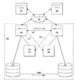
ここで図2を参照すると、フェイルオーバーの際にミドルウェアを効率的に移行させるための高可用性クラスタのハードウェア構成のブロック図が示されている。図示されるように、クライアント・システム202及び204が、サービス要求を転送するためにネットワークに接続される。この実施形態においては、クライアント・システム202及び204は、フェイルオーバーの際の回復時間を短くして受託データの損失を最小限にするように構成された高可用性(HA)システム208から、サービスを要求する。
Referring now to FIG. 2, a block diagram of a hardware configuration of a high availability cluster for efficiently migrating middleware during a failover is shown. As shown,
図示されるように、HAシステム208は、1次ノード210及び2次ノード220を含む。以下に説明するように、1次ノード210及び2次ノード220は、実行時には高可用性システムとなる冗長化ハードウェア及びソフトウェアを実装することが好ましい。具体的には、以下に説明するように、1次ノード210及び2次ノード220は、好ましい実施形態においてはJ2EEアプリケーションに対応する冗長化ミドルウェアを実装する。ミドルウェアとは、ウェブ・アプリケーション及びシステムを開発し、統合し、管理するソフトウェアである。以下に説明するように、ミドルウェアは、通信、処理、データの統合と、トランザクション能力管理及びシステム管理の自動化とを可能にする。
As shown, the
具体的には、Java(商標)2プラットフォーム、エンタープライズ・エディション(J2EE)は、ウェブ・アプリケーションの作成に用いるための再利用可能なコンポーネント・モデルを提供する。J2EEは、標準アプリケーション・モデルと、アプリケーションのホストとして動作するための標準プラットフォームと、互換性必要条件と、J2EEプラットフォームのオペレーション定義とを定める。このオープン・ソース・モデルの利点は、多数の開発者が付加的なコンポーネント及び構成と共にJ2EEモデルを実装することが可能で、さらに、すべてのJ2EEアプリケーションがJ2EEベースのシステム上で稼動することである。 Specifically, the Java ™ 2 platform, Enterprise Edition (J2EE) provides a reusable component model for use in creating web applications. J2EE defines a standard application model, a standard platform for operating as an application host, compatibility requirements, and operation definitions for the J2EE platform. The advantage of this open source model is that many developers can implement the J2EE model with additional components and configurations, and that all J2EE applications run on J2EE-based systems. .
インターナショナル・ビジネス・マシーンズ・コーポレーション(IBM(商標))の開発者は、J2EEモデルを実装するソフトウェアを開発した。このソフトウェアは、多くの場合、J2EEフレームワークでは規定されない隙間の部分を埋めるものである。例えば、具体的には、IBM(商標)は、サーバのクラスタに実装されるとJ2EEアプリケーションに対応するJ2EE準拠ソフトウェアであるミドルウェア・スタックを開発した。一般に、ミドルウェア・スタックとして、ウェブ・サーバ、データベース・サーバ、及びユニバーサル・インターネット・アプリケーション・サーバが挙げられる。具体的には、このスタックとして、IBM DB2(商標)UDB Enterprise Edition、IBM HTTP Server、及び、IBMWebSphere(商標)Application Serverなどの製品を挙げることができる。 Developers of International Business Machines Corporation (IBM ™) have developed software that implements the J2EE model. This software often fills gaps that are not defined by the J2EE framework. For example, specifically, IBM ™ has developed a middleware stack that is J2EE compliant software that, when implemented in a cluster of servers, supports J2EE applications. In general, middleware stacks include web servers, database servers, and universal internet application servers. Specifically, products such as IBM DB2 (trademark) UDB Enterprise Edition, IBM HTTP Server, and IBM WebSphere (trademark) Application Server can be cited as the stack.
さらに、1次ノード210及び2次ノード220は、HAクラスタのJ2EE準拠ミドルウェア・スタック及びハードウェアの故障及びエラーを監視する監視・構成コントローラを実装する。監視・構成コントローラの例として、J2EEフレームワークで稼動するソフトウェアを監視するための隙間の部分を埋め、J2EEフレームワークが稼動するシステムの構成を容易にする、Tivoli(商標)Monitoringコントローラを実装することができる。
Further, the
1次ノード210及び2次ノード220は、各々のノードが他のノードのハートビートを迅速に検査することを可能にする信頼性の高い簡単な方法で、接続される。実施形態においては、この接続は、各々のノードにおけるネットワーク・アダプタ間に接続されるクロスケーブル218によって可能になる。具体的には、クロスケーブル218は、ハートビート・データを転送するためのイーサネット(登録商標)接続を可能にすることが好ましい。代替的には、ハートビート・データは、クロスケーブル218が故障した場合に、ネットワーク102を経由して公衆IP接続間で転送することもできる。ハートビートの通信チャネルを1次ノード210と2次ノード220との間に提供するために他のハードウェアを実装しても良いこと、及び、ネットワークを基盤とする接続に加えてシリアル接続を実装しても良いことが理解されるであろう。
具体的には、ハートビート信号が1次ノード210と2次ノード220との間でクロスケーブル218を通して送られるとき、該ハートビートが機能しなくなった場合には、2次ノード220が、故障の前に1次ノード210によって提供されたサービスを引き継ぐことになる。しかしながら、以下に説明するように、本発明の利点によるとミドルウェア・コンポーネントは、ハートビート故障をさらに分析し、2次ノード220が1次ノード210によって提供されるサービスを引き継ぐ前に、該故障に関する付加的な情報を提供することができる。そのうえ、以下に説明するように、Linuxによるハートビート及びLinuxによらないハートビートは共に、クロスケーブル218を介して監視することができる。
Specifically, when a heartbeat signal is sent between the
1次ノード210及び2次ノード220は、データ記憶システム214及び224にアクセスする。有利なことに、ここではdrbdパーティション230として示されるデータ・リプリケータが、1次ノード210と2次ノード220との間で実際に物理的に共有される記憶装置を必要とせずに1次ノード及び2次ノードによってアクセス可能なデータを複製するために、データ記憶装置214及び224の各々のパーティションを含む。本発明の利点によると、drbdは、フェイルオーバーの際の1次ノード210から2次ノード220へのデータ転送を容易にするために、パーティション上で稼働するように構成される。本発明は、drbdスクリプトによって管理されるdrbdパーティションに関して説明されるが、他の分散型データ複製システムを実装しても良いことが理解されるであろう。
無停電電源装置(UPS)212及びUPS222の各々は、それぞれ1次ノード210及び2次ノード220に独立電源を供給する。好ましくは、UPS212と2次ノードとの間、及び、UPS222と1次ノード210との間にも、接続が確立される。一実施形態においては、シリアルケーブル216が1次ノード210とUPS222との間に設けられ、シリアルケーブル226が2次ノード220とUPS212との間に設けられる。しかしながら、他の形式の接続ハードウェアを実装しても良いことが理解されるであろう。
Each of the uninterruptible power supply (UPS) 212 and
本発明の利点によると、1次ノード210に故障が検出されたとき、2次ノード220は、事前に1次ノード210に向けられた要求をフェイルオーバー後に受信し始める。1次ノード210上で稼働しているハードウェア、ソフトウェア、又はネットワークの一部のみが故障することがあるため、該1次ノード210がフェイルオーバー後にデータを更新しないようにすることを保証する唯一の方法は、UPS212の電源を切ることである。有利なことに、以下に説明するように、待機ノード220へのフェイルオーバーが検出されたときは、電源を切る命令を該待機ノード220からUPS212に送るために、本明細書でさらに詳細に説明されるSTONITHがクラスタ・マネージャによって実行される。
According to the advantages of the present invention, when a failure is detected at the
ここで図3を参照すると、本発明の方法、システム、及びプログラムに係るクラスタ・マネージャのブロック図が示されている。図示されるように、クラスタ・マネージャ322には、効率的なフェイルオーバーを実行するのに利用される、ハートビート・ツール402と、drbdスクリプト404と、mon406と、STONITH機能408とを含む多数のコンポーネントが組み込まれる。クラスタの他の状況を管理するために、他のコンポーネントをクラスタ・マネージャに組み込んでも良いことが理解されるであろう。さらに、フェイルオーバーを管理するために、付加的なコンポーネントをクラスタ・マネージャ322に組み込んでも良いことが理解されるであろう。
Referring now to FIG. 3, a block diagram of a cluster manager according to the method, system, and program of the present invention is shown. As shown, the
ハートビート・ツール402は、J2EE準拠ハードウェア・スタックを用いるHAクラスタ内部のフェイルオーバーを管理するために構成される、Linux用のハートビート・パッケージを含むことが好ましい。具体的には、ハートビート・ツール402は、一般に、クラスタの2つのノード間で「ハートビート」要求を送信することによって作動する。図2で説明されたように、ハートビート要求は、各々のノードにおけるネットワーク・アダプタ間でクロスケーブルを通して送信することができる。サーバ・システムのクラスタ上で稼働するJ2EE準拠ミドルウェア・スタックに使用されるときは、ハートビート・ツール402によって送信されるハートビート要求は、スタックの異なる層全体に配信される。 The heartbeat tool 402 preferably includes a heartbeat package for Linux configured to manage failover within the HA cluster using a J2EE compliant hardware stack. Specifically, the heartbeat tool 402 generally operates by sending a “heartbeat” request between two nodes of the cluster. As described in FIG. 2, a heartbeat request can be sent over a cross cable between network adapters at each node. When used on a J2EE compliant middleware stack running on a cluster of server systems, heartbeat requests sent by the heartbeat tool 402 are distributed across different layers of the stack.
ハートビート要求が戻されない場合には、2次ノードは、1次ノードが故障したものと想定し、該1次ノード上で稼働していたIP、データ、及びサービスを引き継ぐことができる。2次ノードが、1次ノード上で稼働していたIP、データ、及びサービスを引き継ぐときは、ハートビート・ツール402は、待機モードで待機している該2次ノードのコンポーネントを起動し、IPアドレスを該2次ノードのコンポーネントに割り当て、他のフェイルオーバー・タスクを実行する。 If the heartbeat request is not returned, the secondary node assumes that the primary node has failed and can take over the IP, data, and services that were running on the primary node. When the secondary node takes over the IP, data, and services that were running on the primary node, the heartbeat tool 402 activates the secondary node component that is waiting in standby mode, Assign an address to the component of the secondary node to perform other failover tasks.
drbd404は、フェイルオーバーの際のデータ切り替えを改善するための、HAクラスタのデータを管理する関連スクリプトをもつカーネル・モジュールである。この切り替えは、drbd404によって管理されるブロック・デバイスをミラーリングすることにより行われる。drbdは、drbdモジュールを読み込み、HAクラスタの関連システム及び共有記憶装置のIPアドレスを用いて構成するスクリプトである。 The drbd 404 is a kernel module having a related script for managing data of the HA cluster for improving data switching at the time of failover. This switching is performed by mirroring the block device managed by drbd 404. drbd is a script that reads the drbd module and configures it using the IP addresses of the HA cluster related system and the shared storage device.
J2EE準拠ミドルウェア・スタックに使用されるときは、drbd管理ブロック・デバイスは、該ミドルウェア・スタックが稼働することができる記憶装置を提供する。当初は、1次ノードのみがdrbd管理ブロック・デバイスから読み込むか又は書き込むことができるように、クラスタが構成され、drbdパーティションがマウントされる。フェイルオーバーが発生したときは、2次ノードのみがdrbd管理ブロック・デバイスから読み込み/書き込みができるようにdrbdパーティションをマウントするために、drbd404のデータディスク・スクリプトがハートビート・ツール402によって実行される。 When used in a J2EE compliant middleware stack, the drbd management block device provides a storage device on which the middleware stack can run. Initially, the cluster is configured and the drbd partition is mounted so that only the primary node can read or write from the drbd management block device. When a failover occurs, the data disk script of drbd 404 is executed by the heartbeat tool 402 to mount the drbd partition so that only the secondary node can read / write from the drbd management block device .
mon406は、J2EE準拠ミドルウェア・スタック内部の重要なシステム・サービスを監視する監視スクリプトを定期的に実行するサービス監視デーモンである。サービスが機能しなくなったか又は異常終了したことが発見された場合には、mon406は、該サービスを再開させて、ミドルウェア・スタックのすべてのコンポーネントが1次サービスの範囲内で引き続き稼働し続けることを保証する。異常終了は、例えば、プログラミング・エラー、又は、RAMを原因とする一時的なクリティカル・リソース制約などの突発的なオペレーティング・システム事象によって発生することがある。具体的には、monがサービスを再開させるときは、該monは、休止サービスとはプロセス識別子(PID)は異なるが、同一の仮想IPアドレスをもつサービスの新たなインスタンスを再開させる。
The
STONITH408は、フェイルオーバーの際のデータ保全を保証するために、ハートビート・ツール402によって呼び出される機能である。具体的には、STONITH408は、図2に示されるように、UPS212及び222へのシリアルケーブル構成を含む。ハートビート・ツール402がSTONITH408を呼び出すとき、その呼び出しは、シャットダウンさせるノードを指定する。STONITHは、信号を送信して、要求されたUPSの電源を切る。
監視・構成コントローラ410は、HAクラスタ内部のハードウェア及びソフトウェアのステータスを監視するように指定された多数の監視コントローラを含む。本発明の利点によると、HAクラスタの多数のハードウェア及びソフトウェア・コンポーネントに関するステータス情報は、遠隔集中エンタープライズ・コンソールに送られる。好ましくは、監視・構成コントローラ410は、Java(商標)Management Extensions(JMX)を補完して、HAクラスタのハードウェア及びソフトウェア・コンポーネントを監視し、障害及び潜在的な問題を検出し、該クラスタを自動的に危機的な状態から回復させる。一実施形態においては、監視コントローラは、監視情報をTivoli(商標)Enterprise Console(TEC)に送るTivoli(商標)Monitoringによって使用可能にされる。
The monitoring and
具体的には、ハートビート・ツール402及びmon406が、ノード内部の特定のコンポーネント及びサービスの特定のインスタンスを監視する一方で、監視・構成コントローラ410は、これらのツールによって監視された状態を検出し、フェイルオーバーを開始するようにハートビート・ツール402が起動されるか又はサーバを再始動させるようにmon406が起動されるときには、システムの全ステータスを検出する。このように、監視・構成コントローラ410は、故障、エラー、及び非理想的な状態が発生したときに、ノードの多数のコンポーネントのステータスを収集することによって、オープン・ソース・ツールを補完するものである。
Specifically, heartbeat tools 402 and
本発明の1つの利点として、遠隔集中監視コンソールは、集められた情報を用いて構成変更を判断することができる。具体的には、本発明の利点によると、監視・構成コントローラ410の監視コントローラの各々は、HAクラスタの各々のハードウェア・コンポーネントと、J2EE準拠ミドルウェア・スタックの層の各々とを監視するように構成される。このように、コンソールは、ハードウェア及びミドルウェア層に関する監視情報に基づいて、どのミドルウェア層が、要求をキャッシュするためにより多くのメモリを必要とするか、要求を処理するためにより多くのスレッドを必要とするか、又は他の幾つかの方法で再構成されることを必要とするかを判断することができる。コンソールは、構成変更を監視・構成コントローラ410の構成コントローラに送信することができ、次いで、この構成コントローラは、HAクラスタの構成を調整する。一実施形態においては、構成コントローラは、HAクラスタの構成特性を管理するTivoli(商標)Configuration Managerである。
As one advantage of the present invention, the remote centralized monitoring console can use the collected information to determine configuration changes. Specifically, according to the advantages of the present invention, each of the monitoring controllers of the monitoring and
本発明の別の利点として、エンタープライズ・システムにおいては、コンソールは、集められた情報を用いて、どのHAクラスタがハードウェア及びソフトウェアの更新を必要とするかを判断する。例えば、監視情報について、コンソールは、どの記憶装置が故障している様子の交換が必要なハードウェアを有するか、どの記憶装置が最大容量に達して更新が必要なハードウェアを有するか、及び、どの記憶装置が機能していないか又は確実に稼働していないソフトウェアを有するかを判断することができる。 As another advantage of the present invention, in an enterprise system, the console uses the collected information to determine which HA cluster requires hardware and software updates. For example, for monitoring information, the console has which storage device has the hardware that needs to be replaced, which storage device has the maximum capacity and needs to be updated, and It can be determined which storage devices are not functioning or have software that is not running reliably.
本発明のさらに別の利点として、監視・構成コントローラ410は、クラスタ・マネージャ322内部の他の監視コンポーネントと情報交換を行って、コンソールに送られるステータス情報を収集する。例えば、mon406が、監視状態にあるサービスのいずれかの故障を検出したときは、監視・構成コントローラ410は、システムにおける故障の全体像を収集することができるように、通知を遠隔集中監視コンソールに送信する。さらに、ハートビート・ツール402がシステムの1つのノードから別のノードへのフェイルオーバーを開始したときは、監視・構成コントローラ410は、ノード故障の統計情報を収集することができるように、通知を遠隔集中監視コンソールに送信する。
As yet another advantage of the present invention, the monitoring and
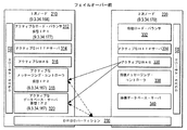
ここで図4を参照すると、本発明の方法、システム、及びプログラムに係る、フェイルオーバー前のHAクラスタにおけるソフトウェア構成の一実施形態のブロック図が示されている。図示されるように、1次ノード210及び2次ノード220はサーバ・システムのクラスタを表し、各々のクラスタはIPアドレスに割り当てられる。
Referring now to FIG. 4, a block diagram of one embodiment of a software configuration in an HA cluster before failover according to the method, system, and program of the present invention is shown. As shown,
本発明の利点として、クラスタ・マネージャ322は、1次ノード210及び2次ノード220上で稼働して、故障を監視し、サービスを再開し、故障が検出されたときにはフェイルオーバーを制御する。図示されるように、クラスタ・マネージャ322は、1次ノード210と2次ノード220との間で共有される記憶装置上に配置されるdrbdパーティション230を構成する。
As an advantage of the present invention, the
1次ノード210は、ミドルウェア・スタックのすべてのアクティブなコンポーネント、すなわち、ロード・バランサ312、HTTPサーバ314、ウェブ・アプリケーション・サーバ(WAS)316、メッセージング・コントローラ318、及びデータベース・サーバ320を含む。2次ノード220は、アクティブなHTTPサーバ334及びWAS336を含むが、ロード・バランサ332、メッセージング・コントローラ338、及びデータベース340は、待機モードである。
The
ロード・バランサ312及び332は、クラスタ化することもできるHTTPサーバとWASサーバとの間で要求の負荷を平準化することが好ましい。好ましくは、ロード・バランサ312及び332は、サーバの可用性、容量、作業負荷、及び他の基準を用いて、インテリジェント負荷平準化を行う。一実施形態によると、ロード・バランサ312及び332は、IBM WebSphere(商標)Edge Serverを介して実装することができる。
The load balancers 312 and 332 preferably balance the load of requests between HTTP servers and WAS servers that can also be clustered. Preferably,
図示されるように、ロード・バランサ312及び332は、Linuxベースのハートビートとは無関係のハートビートを実装することができる。代替的には、Linuxベースのハートビート・モニタ332及び342が、ロード・バランサ312及び332のステータスを監視するようにしてもよい。
As shown,
HTTPサーバ314及び334は、HTTP要求を受信し、HTTP要求をそれぞれWAS316及び336の間で分散させるように設計されたサーバのクラスタを含むことができる。さらに、HTTPサーバ314及び334は、サーブレット及びEJBについての要求などの他の要求を受信したときに、サーブレット・コンテナ及びEnterprise Java(商標)Bean(EJB)コンテナなどのイネーブラを呼び出すことができるようにされる。一実施形態においては、HTTPサーバ314及び334は、IBMのWebSphere(商標)、特にWebSphere(商標)v.5.0に組み込まれたHTTPサーバを介して実装することができる。WebSphere(商標)コンポーネントの多数の複製を1か所から制御することができるため、WebSphere(商標)v.5.0は有利である。このように、構成変更は、多数のサーバ・システムに配置されたソフトウェア・コンポーネントの多数のインスタンスを生じさせる1つの場所で行うことができる。 HTTP servers 314 and 334 may include a cluster of servers designed to receive HTTP requests and distribute HTTP requests among WAS 316 and 336, respectively. In addition, HTTP servers 314 and 334 can call enablers such as servlet containers and Enterprise Java (TM) Bean (EJB) containers when receiving other requests, such as requests for servlets and EJBs. Is done. In one embodiment, the HTTP servers 314 and 334 are IBM's WebSphere ™, in particular the WebSphere ™ v. It can be implemented via an HTTP server embedded in 5.0. Because multiple copies of WebSphere ™ components can be controlled from a single location, WebSphere ™ v. 5.0 is advantageous. In this way, configuration changes can be made at one location that results in multiple instances of software components located on multiple server systems.
本発明の利点として、HTTPサーバ314及び334は、1次ノードが稼働状態になった後にクラスタ・マネージャ322のハートビート・ツールがHTTPサーバをアクティブにする、アクティブ/アクティブ構成で稼働させられる。HTTPサーバ314及び334をアクティブ/アクティブ構成で稼働させることによって、要求負荷を2つの(又は、それ以上の)サーバにわたって分割して、クライアント要求を処理する速度を速めることができる。さらに、HTTPサーバ314及び334をアクティブ/アクティブ構成で稼働させることによって、フェイルオーバー時の起動時間が短くなる。
As an advantage of the present invention, the HTTP servers 314 and 334 are run in an active / active configuration where the heartbeat tool of the
WAS316及び336は、ミッションクリティカルなサービスを顧客に提供するウェブ・アプリケーションに対応可能なサーバのクラスタを含み、具体的には、これらのサーバは、J2EEアプリケーションに対応可能である。一実施形態によると、WAS316及び336は、J2EEアプリケーション及びサービスに対応するために必要なサーブレット、EJB、及び他のJ2EEコンポーネントのホストとなる、IBMのWebSphere(商標)5.0によってサポートされるWebSphere(商標)Application Serverである。 The WASs 316 and 336 include a cluster of servers capable of supporting web applications that provide mission-critical services to customers, and specifically, these servers can support J2EE applications. According to one embodiment, WASs 316 and 336 are supported by IBM's WebSphere ™ 5.0 that hosts the servlets, EJBs, and other J2EE components required to support J2EE applications and services. (Trademark) Application Server.
WAS316は、メッセージング・コントローラ318及びデータベース・サーバ320と情報交換を行って、メッセージング・コントローラ及びデータベースと一体化したアプリケーション・サーバ機能を提供する。本発明の利点として、WAS316及びWAS336は、アクティブ/アクティブ構成で稼働させられる。具体的には、システムを初期化するときは、メッセージング・コントローラ318及びデータベース・サーバ320が利用可能になると、クラスタ・マネージャ322のハートビート・ツールは、WAS336を立ち上げて、アクティブ/アクティブ構成を作り出す。アクティブ/アクティブ構成で稼働させることによって、要求負荷をシステムの多数のクラスタにわたって分割して、クライアント要求を処理する速度を速めることができる。さらに、アクティブ/アクティブ構成で稼働させることによって、フェイルオーバー時の起動時間が短くなる。
WAS 316 exchanges information with messaging controller 318 and database server 320 to provide application server functionality integrated with the messaging controller and database. As an advantage of the present invention, WAS 316 and WAS 336 are operated in an active / active configuration. Specifically, when the system is initialized, when the messaging controller 318 and the database server 320 become available, the heartbeat tool of the
メッセージング・コントローラ318及び338は、非同期要求を聴取し、これらの要求をローカル・キューに格納して、J2EEベースのシステムと通信するキューを提供するためのコントローラを含む。メッセージング・コントローラ318及び338は、IBM MQSeries(商標)、IBM WebSphere(商標)MQ、又はJava(商標)Messaging Service(JMS)を補完する他のメッセージ・コントローラを実装することができる。
本発明の利点として、メッセージング・コントローラ318及び338は、クラスタ・マネージャ322のdrbdが永続的リソースをdrbdパーティション230のメッセージング・キューで管理し、クラスタ・マネージャ322のハートビート・ツールがフェイルオーバー時にメッセージング・コントローラ338の起動を管理する、アクティブ/待機構成で稼働する。
As an advantage of the present invention, the
データベース・サーバ320及び340は、永続的記憶装置を制御する。データベース・サーバ320及び340は、IBM DB2 UDB Enterprise Edition又は他のリレーショナル・データベース管理システムなどのデータベース制御システムを介して実装することができる。
本発明の利点として、データベース・サーバ320及び340は、クラスタ・マネージャ322のdrbdが永続的リソースをdrbdパーティション230のデータベースで管理し、クラスタ・マネージャ322のハートビート・ツールがフェイルオーバー時にデータベース・サーバ340の起動を管理する、アクティブ/待機構成で稼働する。
As an advantage of the present invention, the
メッセージング・コントローラ318及び338並びにデータベース・サーバ320及び340が、アクティブ/待機構成で稼働し、最小限のデータ損失で迅速にフェイルオーバーを行うために、メッセージング・コントローラ318及びデータベース・サーバ320は、キュー及びデータベースを格納するためのルートとしてdrbdパーティション230がマウントされる位置を指定するように構成される。さらに、クラスタ・マネージャ322は、メッセージング・コントローラ318及びデータベース・サーバ320の仮想IPアドレスを用いて、drbd及びハートビート・ツールを構成する。
In order for
さらに、本発明の利点として、クラスタ・マネージャ322のmon機能は、メッセージング・コントローラ318及びデータベース・サーバ320によって提供されるサービスなどの重要なシステム・サービスを監視する監視スクリプトを定期的に実行する。サービスが機能しなくなったか又は異常終了したことが発見された場合には、monは、該サービスを再開させて、ミドルウェア・スタックのすべてのコンポーネントが1次サービスの範囲内で引き続き稼働し続けることを保証する。
Further, as an advantage of the present invention, the mon function of
効率的なフェイルオーバーを達成するようにミドルウェアの各々の階層を構成し、クラスタ・マネージャ322を通じてミドルウェアの各々の階層を制御する方法は、他のタイプのミドルウェアに応用できることに注目することが重要である。このように、J2EE互換ミドルウェア・ソフトウェア・スタックから利用可能な機能は拡張し続けるので、各々のミドルウェア・コンポーネントを、アクティブ/アクティブ構成又はアクティブ/待機構成のいずれかで構成し、クラスタ・マネージャ322によって監視し、フェイルオーバーの際に制御することができる。
It is important to note that the method of configuring each middleware tier to achieve efficient failover and controlling each middleware tier through the
ここで図5を参照すると、本発明の方法、システム、及びプログラムに係る、フェイルオーバー後のHAクラスタにおけるソフトウェア構成の一実施形態のブロック図が示されている。図示されるように、フェイルオーバー後は、1次ノード210は、故障ノードとして表示される。2次ノード220は、すべてをアクティブなノードとして引き継ぐことになる。
Referring now to FIG. 5, a block diagram of one embodiment of a software configuration in a HA cluster after failover according to the method, system, and program of the present invention is shown. As illustrated, after failover, the
故障が検出され、2次ノード220が1次ノード210を「休止」として指定するときには、ハードウェア及びソフトウェアの問題が存在する。具体的には、1次ノード210が、必要な時間内にハートビート要求に応答せず、その後間もなく作動可能になる場合がある。先に説明されたように、1次ノード210及び2次ノード220が共に作動可能になる状況を回避するために、クラスタ・マネージャ322のハートビート・ツールは、STONITHを呼び出して、1次ノード210へのUPS電源を切ることになる。STONITHによって制御できる安価なUPSを実装することにより、データ保全を達成することが可能であり、1次ノードが実際には休止していないときに生じる可能性のあるHAの「スプリット・ブレイン」問題が回避される。
When a failure is detected and the
次に、フェイルオーバーの際に、ロード・バランサのハートビートは、ロード・バランサ332の起動を管理する。起動されると、クラスタ・マネージャ322のハートビート・ツールは、1次ノード210の仮想IP1アドレスをロード・バランサ332に割り当てる。その結果、仮想IPアドレスに対する要求は、負荷平準化クラスタのIPアドレスの変更が生じないようにロード・バランサ332に転送される。
Next, during a failover, the load balancer heartbeat manages the activation of the
フェイルオーバーの際にはHTTPサーバ334及びWAS336はすでにアクティブなので、クラスタ・マネージャ322のハートビート・ツールは、これらのコンポーネントを起動させる必要はない。しかしながら、メッセージング・コントローラ338及びデータベース・サーバ340は待機状態にあるので、クラスタ・マネージャ322のハートビート・ツールは、これらの層のフェイルオーバーを管理する必要がある。まず、ハートビート・ツールは、仮想IP2アドレスを引き継ぐ。次に、ハートビート・ツールは、drbdのデータディスク・サービスを開始して、drbdミラー・パーティションを構成し、マウントする。最後に、ハートビート・ツールは、仮想IP2アドレスが設定され、ミラーdrbdパーティション230上で立ち上がるメッセージ・キュー及びデータベース・インスタンスをもつ、メッセージ・コントローラ338及びデータベース・サーバ340を起動することになる。代替的に、図示されてはいないが、仮想IP2アドレスは1度に1つのノードのみが利用可能であるため、データベース・サーバ340は、待機状態ではなく、アクティブ・モードにしておいてもよい。データベース・サーバ340は、フェイルオーバー時には、要求が着信するまでdrbdパーティション230上のデータにアクセスしようとしないので、データベース・サーバ340には仮想IP2アドレスが設定され、ミラーdrbdパーティション230は要求が着信する前にアクセス可能である。逆に、メッセージング・コントローラ338などの幾つかの層は、起動時に直接データを読み込むものであり、フェイルオーバー前には2次ノード220はdrbdパーティション230上のデータを利用できないため、フェイルオーバー前に2次ノード220上で起動された場合には破壊されることになる。
Since the HTTP server 334 and WAS 336 are already active during a failover, the
ここで図6を参照すると、HAシステムにおけるJ2EE準拠ミドルウェア内部の独立系ソフトウェア・ベンダー(ISV)アプリケーションの一実施例のブロック図が示されている。図示されるように、アクティブなWAS602と、アクティブなIBM MQSeries(商標)サーバ610と、アクティブなIBM DB2サーバ614とが、drbd630とインターフェース接続しているJ2EE準拠ミドルウェア・スタックの1次ノードの一部を表している。参照数字620で示されるように、明細登録又はトランザクション完了が、アクティブなWebSphere(商標)Application Server602で受信される。ISVは、特定のタイプの着信要求を処理するように、サーブレット又はEJBをプログラムすることができる。例えば、参照数字620で示されるように、ルックアップ・サーブレット604は、項目をキャッシュ・レジスタで走査するときに、その価格を調べる価格ルックアップ(PLU)を処理するISVウェブ・アプリケーションである。ルックアップ・サーブレット604は、次に、トランザクション・サーブレット608又は別のサーブレット若しくはEJBといった別のコンポーネントによって非同期的に完了させられる保持トランザクションについての要求を送信する。しかしながら、まず、参照数字622で示されるように、その情報をMQリスナ612に送り、MQキュー632上に置いて、次の着信要求を受信するようにルックアップ・サーブレット604を解放し、トランザクションがMQキュー632を介して順序良く厳密に1度だけ記録されることを保証する。次に、参照数字624で示されるように、MDB606を呼び出して、トランザクションをMQキュー632から取り出し、参照数字626で示されるように該トランザクションをトランザクション・サーブレット608に送信する。最終的に、トランザクション・サーブレット608は、PLUを処理し、参照数字628で示されるように、DB2 634に格納するために結果をIBM DB2コントローラ616に出力する。
Referring now to FIG. 6, a block diagram of one embodiment of an independent software vendor (ISV) application within J2EE compliant middleware in an HA system is shown. As shown, a portion of the primary node of the J2EE compliant middleware stack in which an active WAS 602, an active IBM
具体的には、要求がすでにスタックの層間で移行し始めた後でフェイルオーバーが生じたとしても、該スタックは各々のトランザクションが厳密に一度だけ記録されることを保証するため、図6は、フェイルオーバーの際のHAシステムにおけるJ2EE準拠ミドルウェア・スタックの利点を示す。さらに、アクティブ層のMQSeries(商標)サーバ610及びDB2サーバ614は、1次ノードのみがアクセス可能であるが、フェイルオーバーの際には2次ノードによるアクセスのために迅速に再マウントされるdrbdパーティション630とインターフェース接続するため、図6は、フェイルオーバーの際のHAシステムにおけるJ2EE準拠ミドルウェア・スタックの利点を示す。
Specifically, even if a failover occurs after a request has already begun to move between stack layers, the stack ensures that each transaction is recorded exactly once, so FIG. The advantages of a J2EE compliant middleware stack in an HA system during failover are shown. In addition, the active layer MQSeries (TM)
ここで図7を参照すると、HAクラスタのJ2EE準拠ミドルウェア・スタックにdrbdパーティションを構成するための処理及びプログラムの概略的な論理フローチャートが示されている。図示されるように、処理は、ブロック700で開始し、その後、ブロック702に進む。ブロック702は、drbdパーティションを構成し、マウントするステップを示す。次のブロック704は、drbdパーティション上のメッセージ・キュー及びデータベースをアクティブにするステップを示す。その後のブロック706は、フェイルオーバーの際にdrbdパーティションへのアクセスを効率的に移すために、drbdパーティションにアクセスするメッセージング・サーバ及びデータベース・サーバの仮想IPアドレスを記録するステップを示し、処理は終了する。
Referring now to FIG. 7, there is shown a schematic logic flow diagram of processing and programs for configuring a drbd partition in a HA cluster J2EE compliant middleware stack. As shown, processing begins at block 700 and then proceeds to block 702.
ここで図8を参照すると、HAクラスタのJ2EE準拠ミドルウェア・スタックの構成及びフェイルオーバーを、ハートビート・コントローラを通じて制御するための処理及びプログラムの概略的な論理フローチャートが示されている。示されるように、処理は、ブロック800で開始し、その後、ブロック802に進む。ブロック802は、1次ノードのミドルウェア層をアクティブにするステップを示す。その後のブロック804は、2次ノードのHTTPサーバ及びWASミドルウェア層をアクティブにするステップを示す。さらに、アクティブ/アクティブ構成で稼動するように指定される他のミドルウェア層がアクティブにされる。その後のブロック806は、2次ノードから1次ノードへのハートビート要求を定期的に起動するステップを示す。ブロック808は、ハートビートの戻りが2次ノードによって検出されたかどうかの判断を示す。ハートビートの戻りが検出された場合には、処理は806に戻る。ハートビートの戻りが検出されない場合には、処理はブロック810に移行する。
Referring now to FIG. 8, there is shown a schematic logic flow diagram of processes and programs for controlling the configuration and failover of a HA cluster J2EE compliant middleware stack through a heartbeat controller. As shown, processing begins at block 800 and then proceeds to block 802.
ブロック810は、STONITHを呼び出して、1次ノードの電源を切るステップを示す。次のブロック812は、仮想IPアドレスを1次ノードから引き継いで、2次ノードの冗長化コンポーネントに割り当てるステップを示す。その後のブロック814は、データディスク・スクリプトを呼び出して、2次ノードによるアクセスのためにdrbdパーティションを再マウントするステップを示す。次いで、ブロック816は、2次ノード上の待機ミドルウェア層と、drbdパーティション上の起動データとをアクティブにするステップを示す。フェイルオーバーの際に、ハートビート・ツール及び他のクラスタ管理サービスによって付加的なステップを実施しても良いことが理解されるであろう。
ここで図9を参照すると、J2EE準拠ミドルウェア・スタックによって提供されるサービスを監視するためにmon機能を制御する処理及びプログラムの概略的な論理フローチャートが示されている。図示されるように、処理は、ブロック900で開始し、その後、ブロック902に進む。ブロック902は、ミドルウェアによって提供されるサービスを監視するためのスケジュールを設定するステップを示す。次のブロック904は、予定された時間監視を起動させるかどうかの判断を示す。予定された時間監視が起動されない場合には、処理はブロック904で繰り返される。予定された時間監視が起動された場合には、処理はブロック906に移行する。ブロック906は、予定されたサービスのステータスを監視するステップを示す。その後のブロック908は、サービスが何らかの方法で休止又は故障として検出されたかどうかの判断を示す。サービスが休止として検出されない場合には、処理は終了する。サービスが休止として検出された場合には、処理はブロック910に移行する。ブロック910は、新たなPIDを用いて同一のサービスを再開するステップを示し、処理は終了する。
Referring now to FIG. 9, there is shown a schematic logic flow diagram of a process and program for controlling the mon function to monitor services provided by a J2EE compliant middleware stack. As shown, processing begins at block 900 and then proceeds to block 902.
ここで図10を参照すると、本発明の方法、システム、及びプログラムに従って、J2EEミドルウェア・スタックが稼動し、遠隔エンタープライズ・コンソールによって管理される多数のHAシステムを含むエンタープライズ・ネットワークのブロック図が示されている。図示されるように、HAシステム1202及びHAシステム1204が、ネットワーク102を介してHAシステム1202及び1204を監視し、遠隔的に制御する遠隔エンタープライズ・コンソール1210に通信接続される。多数のHAシステムを、単一又は多数の遠隔集中コンソールによって監視し、制御できることが理解されるであろう。
Referring now to FIG. 10, there is shown a block diagram of an enterprise network that includes multiple HA systems running a J2EE middleware stack and managed by a remote enterprise console in accordance with the method, system, and program of the present invention. ing. As shown,
本発明の利点として、HAシステム1202及び1204の各々は、小売トランザクション及び他のミッションクリティカルな作業を処理することができる。一実施形態によると、HAシステム1202及び1204の各々には、図4及び図5に示されたミドルウェア・スタックなどの、J2EEアプリケーションを使用可能にする冗長化J2EE準拠ミドルウェア・スタックによって、高可用性を与えることができる。具体的には、HAシステム1202及び1204の各々は、図3に示されるように、監視・構成コントローラ410を稼働させるクラスタ・マネージャを含む。
As an advantage of the present invention, each of
有利なことに、エラー、故障、又は非理想的な状態がHAシステム1202及び1204のいずれかで発生したときは、監視・構成コントローラ410は、そのエラー、故障、又は非理想的な状態の時点におけるシステムの状態を検出し、次に、情報を収集して、遠隔エンタープライズ・コンソール1210に対する報告を作成する。本発明の利点として、ハートビート・モニタ又はmon機能が故障又はエラーを検出した場合には、監視・構成コントローラ410が起動して、その故障又はエラーを検出し、故障又はエラーの時点のシステム状態を判断する。
Advantageously, when an error, failure, or non-ideal condition occurs in any of the
遠隔エンタープライズ・コンソール1210は、監視情報をデータベースに格納することが好ましい。次に、遠隔エンタープライズ・コンソール1210は、HAシステム1202及び1204から受信したエラー又は故障の情報を分析し、場合によっては構成変更をHAシステムに戻して、フェイルオーバーの回避、及びフェイルオーバー効率の改善を試みる第1のコントローラを含むことが好ましい。さらに、遠隔エンタープライズ・コンソール1210は、多数のHAシステムから受信した故障情報、エラー情報、又は他の情報を比較して、どのシステムが修復及び更新を必要とし、どのシステムが性能要件を満たしていないかを判断する第2のコントローラを含むことができる。遠隔エンタープライズ・コンソール1210は、HAシステム1202及び1204についての性能統計を収集して、その表示を制御することができる。
The remote enterprise console 1210 preferably stores the monitoring information in a database. The remote enterprise console 1210 then analyzes the error or failure information received from the
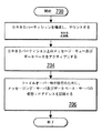
ここで図11を参照すると、本発明の方法、システム、及びプログラムに係るHAクラスタ・マネージャ内部の監視コントローラを制御するための処理及びプログラムの概略的な論理フローチャートが示されている。図示されるように、処理は、ブロック1000で開始し、その後、ブロック1002に進む。ブロック1002は、故障又はエラーが、HAシステムのミドルウェア・スタックを監視するハートビート・モニタ、mon、又は他の監視コントローラから検出されたかどうかの判断を示す。故障又はエラーが検出されない場合には、ブロック1002において処理が繰り返される。故障又はエラーが検出された場合には、処理は1004に移行する。ブロック1004は、故障又はエラーの時点で利用可能なシステム情報を収集し、分析するステップを示す。次のブロック1006は、故障又はエラーの情報、及び利用可能なシステム情報を、HAシステムを監視する遠隔集中コンソールに送信するステップを示し、処理は終了する。
Referring now to FIG. 11, there is shown a schematic logic flow diagram of a process and program for controlling a supervisory controller within the HA cluster manager according to the method, system and program of the present invention. As shown, processing begins at block 1000 and then proceeds to block 1002.
ここで図12を参照すると、HAシステムのクラスタ・マネージャを遠隔的に制御して該HAシステムを再構成するための処理及びプログラムの概略的な論理フローチャートが示されている。図示されるように、処理は、ブロック1100で開始し、その後、ブロック1102に進む。ブロック1102は、ミドルウェア・スタックが稼働しているHAシステムを再構成するための構成要求を、遠隔エンタープライズ・コンソールから受信したかどうかの判断を示す。要求を受信しない場合には、ブロック1102において処理が繰り返される。要求を受信した場合、処理はブロック1104に移行する。ブロック1104は、ハートビート・モニタを呼び出して、HAシステムのフェイルオーバー設定を再構成するステップを示し、処理は終了する。さらに、HAシステムのクラスタ・マネージャ内部の他のコントローラを呼び出して、HAシステムの他のソフトウェア及びハードウェア構成を調整することができる。
Referring now to FIG. 12, there is shown a schematic logic flow diagram of a process and program for remotely controlling the HA system cluster manager to reconfigure the HA system. As shown, processing begins at block 1100 and then proceeds to block 1102.
ここで図13を参照すると、クラスタにおける多数のHAシステムを管理するために遠隔エンタープライズ・コンソールを制御する処理及びプログラムの概略的な論理フローチャートが示されている。図示されるように、処理は、ブロック1300で開始し、その後、ブロック1302に進む。ブロック1302は、監視情報がHAシステムから受信されたかどうかの判断を示す。監視情報が受信されない場合には、ブロック1302において処理が繰り返される。監視情報が受信された場合には、処理はブロック1304に移行する。具体的には、遠隔エンタープライズ・コンソールは、監視情報についての要求をHAシステムの各々に定期的に送信することができ、各々のHAシステムもまた、監視情報を自動的に送信することができる。
Referring now to FIG. 13, there is shown a schematic logical flowchart of the process and program for controlling a remote enterprise console to manage multiple HA systems in a cluster. As shown, processing begins at block 1300 and then proceeds to block 1302.
ブロック1304は、多数のHAシステムからの監視情報を格納するエンタープライズ・データベースに監視情報を追加するステップを示す。次のブロック1306は、監視情報が再構成のきっかけとなる場合に、HAシステムの再構成を要求するステップを示す。具体的には、遠隔エンタープライズ・コンソールは、特定の形式のエラーが監視情報中に検出されたときに要求されることになる所定の構成を含むことができる。代替的には、システム管理者が、特定の形式のエラーに対する構成のタイプを推奨するようにしても良い。その後のブロック1308は、監視情報に基づいて、HAシステムについての性能統計を再計算するステップを示す。具体的には、性能統計の計算は、ある種の監視エラー又は変動についてのみ起動されることになる。次のブロック1312は、このHAシステムの性能を、エンタープライズ・ネットワークの他のHAシステムの性能、及び、該エンタープライズ・ネットワークについて設定された性能要件と比較するステップを示す。次いで、ブロック1314は、性能の比較結果をチャート及びグラフで表示するステップを示す。例えば、チャートは、HAシステムの位置の図形表現を描き、どのシステムが故障したかについての図形標識を提供し、他のHAシステムに対する各々のHAシステムの性能を示す図形標識を提供することができる。さらに、各々のシステムの実時間性能と、報告されたあらゆるエラーとを表示することができる。次のブロック1316は、HAシステムの脆弱性に対する修正措置を推奨するステップを示し、処理は終了する。例えば、この推奨は、どのHAシステムが交換を必要とするか、どのHAシステムが更新を必要とするか、及び、どのHAシステムがソフトウェア更新又は微調整を必要とするかを示すものとすることができる。図13に示される処理は、多数の高可用性サーバから受信される監視情報に関して実施することができる処理の形式の例であり、本発明の範囲から逸脱することなく、他の同様の分析又は出力を実施できることが理解されるであろう。
本発明は、好ましい実施形態に関して具体的に示され、説明されてきたが、当業者であれば、本発明の精神及び範囲から逸脱することなく、形態及び詳細の様々な変更を行うことができることを理解するであろう。 Although the invention has been particularly shown and described with reference to preferred embodiments, various changes in form and detail can be made by those skilled in the art without departing from the spirit and scope of the invention. Will understand.
102:ネットワーク
202、204:クライアント・システム
208:高可用性システム
212、222:UPS
214、224:データ記憶システム
216、226:シリアルケーブル
218:クロスケーブル
210:1次ノード
220:2次ノード
230:DRBDパーティション
102:
214, 224:
Claims (19)
ネットワークを介して遠隔エンタープライズ・サーバに通信接続された複数の高可用性システムのうちの特定の高可用性システムを有し、
前記特定の高可用性システムが、
ウェブ・アプリケーションをサポートするためのミドルウェア・スタックを走らせる一次ノードであって、第1のIPアドレスと、該第1のIPアドレスとは異なり、要求を向けるための仮想IPアドレスを割り当てられる前記1次ノードと、
前記1次ノードの前記ミドルウェア・スタックの複数の層をミラーリングするための冗長ミドルウェア・スタックを走らせる2次ノードであって、前記第1のIPアドレス及び前記仮想IPアドレスとは異なる第2のIPアドレスを割り当てられ、前記冗長ミドルウェア・スタックの前記複数の層のうちの第1の選択されたものがアクティブであって、前記冗長ミドルウェア・スタックの前記複数の層のうちの第2の選択されたものが待機状態である、前記2次ノードと、
前記アクティブなミドルウェア・スタック、すなわち前記複数の層の前記第1の選択されたものに対してアクセス可能なデータをもち、前記1次ノードと2次ノードの間で共有されるデータ複製区画と、
前記1次ノードのみが前記データ複製区画にアクセスできるように前記データ複製区画をマウントし、前記高可用性システムの前記1次ノードの状況を監視し、該状況がエラーを示すことに応答して、前記仮想IPアドレスを前記第1のノードから前記第2のノードに転送し、前記1次ノードに対して電源を切り、前記2次ノードのみがアクセスできるように前記データ複製区画を再マウントし、前記データ複製区画内の前記データに対するアクセスを要求する前記冗長ミドルウェア・スタックの前記複数の層のうちの第2の選択されたものを活動化させる、クラスタ管理コントローラと、
前記クラスタ管理コントローラが、前記1次ノードにおいて前記エラーに反応した時を検出し、前記エラーの時点で、前記高可用性システムの複数のコンポーネントの状態を検出するための監視コントローラであって、前記エラーと、前記複数のコンポーネントの状態を、前記複数の高可用性システムの各々から受け取った別のレポートに基づき前記複数の高可用性システムを管理するようにイネーブルされた前記遠隔エンタープライズ・サーバに報告する、前記監視コントローラとを有し、
前記仮想IPアドレスは、前記1次ノードと前記2次ノードのうち、一度に1つのノードのみが利用可能である、
システム。 A system for enabling remote enterprise management of high availability systems,
Having a particular high availability system of a plurality of high availability systems communicatively connected to a remote enterprise server via a network;
The specific high availability system is
A primary node running a middleware stack for supporting a web application , wherein the first IP address is different from the first IP address and is assigned a virtual IP address for directing a request. The next node,
A secondary node running a redundant middleware stack for mirroring a plurality of layers of the middleware stack of the primary node, wherein the second IP is different from the first IP address and the virtual IP address A first selected one of the plurality of layers of the redundant middleware stack that is assigned an address is active and a second selected of the plurality of layers of the redundant middleware stack The secondary node in which the object is in a standby state;
A data replication partition having data accessible to the active middleware stack, i.e., the first selected of the plurality of tiers, and shared between the primary and secondary nodes ;
Mounting the data replication partition so that only the primary node can access the data replication partition, monitoring the status of the primary node of the high availability system, and in response to the status indicating an error; Transfer the virtual IP address from the first node to the second node, power off the primary node, remount the data replication partition so that only the secondary node can access it, A cluster management controller for activating a second selected one of the plurality of layers of the redundant middleware stack requesting access to the data in the data replication partition;
Said cluster management controller detects when reacted before Symbol errors in the primary node, at the time of the error, a monitoring controller for detecting the state of a plurality of components of said high availability system, the Reporting errors and status of the plurality of components to the remote enterprise server enabled to manage the plurality of high availability systems based on another report received from each of the plurality of high availability systems; The monitoring controller,
The virtual IP address can be used by only one node at a time among the primary node and the secondary node.
system.
前記高可用性システムの前記1次ノードのミドルウェア層によって提供されるサービスのステータスを検出するためのサービス監視デーモンをさらに備えるシステム。 The system of claim 1 for enabling remote enterprise management of a high availability system, wherein the cluster management controller comprises:
The system further comprising a service monitoring daemon for detecting the status of services provided by the middleware layer of the primary node of the high availability system.
ネットワークを介して遠隔エンタープライズ・サーバに通信接続された、複数の高可用性システムうちの特定の高可用性システムの少なくとも1つのコンポーネントのステータスを監視する段階と、
前記特定の高可用性システム内の1次ノードで、ウェブ・アプリケーションをサポートするためのミドルウェア・スタックを走らせる段階であって、前記1次ノードが第1のIPアドレスを割り当てられ、前記1次ノードはさらに、該第1のIPアドレスとは異なり、要求を向けるための仮想IPアドレスを割り当てられる、段階と、
前記特定の高可用性システム内の2次ノードで、前記1次ノードの前記ミドルウェア・スタックの複数の層をミラーリングするための冗長ミドルウェア・スタックを走らせる段階であって、前記2次ノードが前記第1のIPアドレスとは異なる第1のIPアドレスを割り当てられ、前記冗長ミドルウェア・スタックの前記複数の層のうちの第1の選択されたものがアクティブであって、前記冗長ミドルウェア・スタックの前記複数の層のうちの第2の選択されたものが待機状態である、段階と、
前記1次ノードと2次ノードの間で、前記アクティブなミドルウェア・スタックである、前記複数の層の第1の選択されたものに対してアクセス可能なデータをもつデータ複製区画を共有する段階と、
前記1次ノードのみが前記データ複製区画にアクセスできるように前記データ複製区画をマウントし、エラーを示す状況に応答して、前記1次ノードから前記2次ノードに前記仮想IPアドレスを転送することによって前記特定の高可用性システムを調整するように対応し、前記1次ノードに対して電源を切り、前記2次ノードのみアクセスできるように前記データ複製区画を再マウントし、前記データ複製区画内のデータに対するアクセスを要求する前記冗長ミドルウェア・スタックの前記複数の層のうちの第2の選択されたものを活動化させる段階と、
、前記エラーと、前記複数のコンポーネントの状態を、前記複数の高可用性システムの各々から受け取った別のレポートに基づき前記複数の高可用性システムを管理するようにイネーブルされた前記遠隔エンタープライズ・サーバに報告する段階を有し、
前記仮想IPアドレスは、前記1次ノードと前記2次ノードのうち、一度に1つのノードのみが利用可能である、
方法。 A method for enabling remote enterprise management of a highly available system, comprising:
Monitoring the status of at least one component of a particular high availability system of a plurality of high availability systems communicatively connected to a remote enterprise server via a network;
Running a middleware stack to support web applications on a primary node in the particular high availability system, the primary node being assigned a first IP address, and the primary node Is further assigned, unlike the first IP address, a virtual IP address for directing the request;
Running a redundant middleware stack for mirroring a plurality of layers of the middleware stack of the primary node at a secondary node in the particular high availability system, wherein the secondary node is the first node A first IP address different from one IP address is assigned , a first selected one of the plurality of layers of the redundant middleware stack is active, and the plurality of redundant middleware stacks A second selected one of the layers is in a waiting state; and
Sharing a data replication partition between the primary node and the secondary node having data accessible to the first selected one of the plurality of layers, which is the active middleware stack; ,
Mount the data replication partition so that only the primary node can access the data replication partition, and transfer the virtual IP address from the primary node to the secondary node in response to a condition indicating an error. To tune the particular high availability system, turn off the primary node, remount the data replication partition so that only the secondary node is accessible, and within the data replication partition Activating a second selected one of the plurality of layers of the redundant middleware stack requesting access to data;
Reporting the error and the status of the plurality of components to the remote enterprise server enabled to manage the plurality of high availability systems based on another report received from each of the plurality of high availability systems. Having a stage to
The virtual IP address can be used by only one node at a time among the primary node and the secondary node.
Method.
将来のエラーに応答して前記高可用性システムを調整するために前記クラスタ管理コントローラが対応する手法の構成を調整する、ことをさらに含む方法。 The method of claim 7 for enabling remote enterprise management of a high availability system, receiving a configuration request from the remote enterprise server;
Adjusting the configuration of the approach to which the cluster management controller responds to adjust the high availability system in response to a future error.
構成要求を前記遠隔エンタープライズ・サーバから受信し、
前記要求に従って前記高可用性システムのハードウェア構成を調整する、
ことをさらに含む方法。 The method of claim 7 for enabling remote enterprise management of a high availability system comprising:
Receiving a configuration request from the remote enterprise server;
Adjusting the hardware configuration of the high availability system according to the request;
A method further comprising:
ネットワークを介して遠隔エンタープライズ・サーバに通信接続された、複数の高可用性システムうちの特定の高可用性システムの少なくとも1つのコンポーネントのステータスを監視する手段と、
前記特定の高可用性システム内の1次ノードで、ウェブ・アプリケーションをサポートするためのミドルウェア・スタックを走らせる手段であって、前記1次ノードが第1のIPアドレスを割り当てられ、前記1次ノードはさらに、該第1のIPアドレスとは異なり、要求を向けるための仮想IPアドレスを割り当てられる、手段と、
前記特定の高可用性システム内の2次ノードで、前記1次ノードの前記ミドルウェア・スタックの複数の層をミラーリングするための冗長ミドルウェア・スタックを走らせる手段であって、前記2次ノードが前記第1のIPアドレス及び前記仮想IPアドレスとは異なる第2のIPアドレスを割り当てられ、前記冗長ミドルウェア・スタックの前記複数の層のうちの第1の選択されたものがアクティブであって、前記冗長ミドルウェア・スタックの前記複数の層のうちの第2の選択されたものが待機状態である、手段と、
前記1次ノードと2次ノードの間で、前記アクティブなミドルウェア・スタックである、前記複数の層の第1の選択されたものに対してアクセス可能なデータをもつデータ複製区画を共有する手段と、
前記1次ノードのみが前記データ複製区画にアクセスできるように前記データ複製区画をマウントし、エラーを示す状況に応答して、前記1次ノードから前記2次ノードに前記仮想IPアドレスを転送することによって前記特定の高可用性システムを調整するように対応し、前記1次ノードに対して電源を切り、前記2次ノードによるアクセスのため前記データ複製区画を再マウントし、前記データ複製区画内のデータに対するアクセスを要求する前記冗長ミドルウェア・スタックの前記複数の層のうちの第2の選択されたものを活動化させる手段と、
前記エラーの時点で前記高可用性システムの複数のコンポーネントの状態を検出する手段と、
、前記エラーと、前記複数のコンポーネントの状態を、前記複数の高可用性システムの各々から受け取った別のレポートに基づき前記複数の高可用性システムを管理するようにイネーブルされた前記遠隔エンタープライズ・サーバに報告する手段を有し、
前記仮想IPアドレスは、前記1次ノードと前記2次ノードのうち、一度に1つのノードのみが利用可能である、
コンピュータ・プログラム。 A computer program resident on a computer readable medium for enabling remote enterprise management of a high availability system comprising:
Means for monitoring the status of at least one component of a particular high availability system of a plurality of high availability systems communicatively connected to a remote enterprise server via a network;
Means for running a middleware stack for supporting web applications at a primary node in said particular high availability system, said primary node being assigned a first IP address , said primary node Further means, unlike the first IP address, assigned a virtual IP address for directing the request;
Means for running a redundant middleware stack for mirroring a plurality of layers of the middleware stack of the primary node at a secondary node in the particular high availability system, wherein the secondary node is the first node A second IP address different from the virtual IP address and the first selected one of the plurality of layers of the redundant middleware stack is active, and the redundant middleware A means wherein a second selected one of the plurality of layers of the stack is in a waiting state;
Means for sharing a data replication partition with data accessible to the first selected one of the plurality of layers, the active middleware stack , between the primary node and the secondary node; ,
Mount the data replication partition so that only the primary node can access the data replication partition, and transfer the virtual IP address from the primary node to the secondary node in response to a condition indicating an error. To tune the particular high availability system by powering off the primary node, remounting the data replication partition for access by the secondary node, and data in the data replication partition Means for activating a second selected one of the plurality of layers of the redundant middleware stack requesting access to
Means for detecting a state of a plurality of components of the high availability system at the time of the error;
Reporting the error and the status of the plurality of components to the remote enterprise server enabled to manage the plurality of high availability systems based on another report received from each of the plurality of high availability systems. Means to
The virtual IP address can be used by only one node at a time among the primary node and the secondary node.
Computer program.
をさらに有するコンピュータ・プログラム。 14. A computer program according to claim 13 for enabling remote enterprise management of a high availability system, monitoring a primary node and a secondary node each having a plurality of servers implementing a J2EE compliant middleware stack. Means for monitoring the status of said component,
A computer program further comprising:
前記高可用性システムの1次ノードのステータスをハートビート・モニタによって監視するための手段、
をさらに有するコンピュータ・プログラム。 14. A computer program according to claim 13 for enabling remote enterprise management of a high availability system comprising:
Means for monitoring the status of the primary node of the high availability system by a heartbeat monitor;
A computer program further comprising:
前記特定の高可用性システムの前記1次ノードの前記ミドルウェア層によって提供されるサービスのステータスを、サービス監視デーモンによって検出するための手段、
をさらに有するコンピュータ・プログラム。 14. A computer program according to claim 13 for enabling remote enterprise management of a high availability system comprising:
Means for detecting by a service monitoring daemon the status of a service provided by the middleware layer of the primary node of the particular high availability system;
A computer program further comprising:
構成要求を前記遠隔エンタープライズ・サーバから受信するための手段と、
前記高可用性システムを調整するために前記クラスタ管理コントローラが対応する手法の構成を調整するための手段と、
をさらに有するコンピュータ・プログラム。 14. A computer program according to claim 13 for enabling remote enterprise management of a high availability system comprising:
Means for receiving a configuration request from the remote enterprise server;
Means for adjusting the configuration of the approach to which the cluster management controller corresponds to adjust the high availability system;
A computer program further comprising:
構成要求を前記遠隔エンタープライズ・サーバから受信するための手段と、
前記要求に従って前記特定の高可用性システムのハードウェア構成を調整するための手段と、
をさらに有するコンピュータ・プログラム。 14. A computer program according to claim 13 for enabling remote enterprise management of a high availability system comprising:
Means for receiving a configuration request from the remote enterprise server;
Means for adjusting the hardware configuration of the particular high availability system according to the request;
A computer program further comprising:
ネットワークを介して遠隔エンタープライズ・サーバに通信接続された複数の高可用性システムのうちの特定の高可用性システムを有し、
前記高可用性システムの各々が、更に、
ウェブ・アプリケーションをサポートするためのミドルウェア・スタックを走らせる1次ノードであって、該ミドルウェア・スタックの複数の層が活動的であり、前記1次ノードが第1のIPアドレスを割り当てられ、さらに、該第1のIPアドレスとは異なり、要求を向けるための仮想IPアドレスを割り当てられる前記1次ノードと、
前記1次ノードの前記ミドルウェア・スタックの複数の層をミラーリングするための冗長ミドルウェア・スタックを走らせる2次ノードであって、前記冗長ミドルウェア・スタックの前記複数の層のうちの第1の選択されたものがアクティブであって、前記第1のIPアドレス及び前記仮想IPアドレスとは異なる第2のIPアドレスを割り当てられ、前記冗長ミドルウェア・スタックの前記複数の層のうちの第2の選択されたものが待機状態である、前記2次ノードと、
前記1次ノードと、前記アクティブ・ミドルウェア・スタックである、前記複数の層の第1の選択されたものに対してアクセス可能なデータをもつ2次ノードの間で、共有されるデータ複製区画と、
前記1次ノードのみが前記データ複製区画にアクセスできるように前記データ複製区画をマウントし、前記高可用性システムの前記1次ノードの状況を監視し、該状況がエラーを示すことに応答して、前記仮想IPアドレスを前記第1のノードから前記第2のノードに転送し、前記1次ノードに対して電源を切り、前記2次ノードのみがアクセスできるように前記データ複製区画を再マウントし、前記データ複製区画内の前記データに対するアクセスを要求する前記冗長ミドルウェア・スタックの前記複数の層のうちの第2の選択されたものを活動化させる、クラスタ管理コントローラと、
前記ステータスがエラーを示すのと同時に、前記複数の高可用性システムの各々の個別のものの複数のコンポーネントについての監視された情報を検出するための監視コントローラと、
前記ネットワークに通信接続された、遠隔エンタープライズ・サーバであって、前記個別の監視コントローラから前記複数の高可用性システムの各々についての前記監視された情報を受け取り、前記監視された情報を解析し、再構成によって調整可能なエラーを示す監視された情報を提出する、前記高可用性システムの各々に対して再構成の要求を送る前記遠隔エンタープライズ・サーバとを有し、
前記仮想IPアドレスは、前記1次ノードと前記2次ノードのうち、一度に1つのノードのみが利用可能である、
システム。 A system for remotely configuring multiple high availability systems,
Having a particular high availability system of a plurality of high availability systems communicatively connected to a remote enterprise server via a network;
Each of the high availability systems further comprises:
A primary node running a middleware stack to support web applications, wherein multiple layers of the middleware stack are active, the primary node is assigned a first IP address, and Unlike the first IP address, the primary node assigned a virtual IP address for directing the request;
A secondary node running a redundant middleware stack for mirroring a plurality of layers of the middleware stack of the primary node, the first selected of the plurality of layers of the redundant middleware stack Is active, is assigned a second IP address different from the first IP address and the virtual IP address, and is second selected from the plurality of layers of the redundant middleware stack The secondary node in which the object is in a standby state;
Said primary node, wherein an active middleware stack, between the secondary node having a first selected data accessible against those which of said plurality of layers, and data replication partition shared ,
Mounting the data replication partition so that only the primary node can access the data replication partition, monitoring the status of the primary node of the high availability system, and in response to the status indicating an error; Transfer the virtual IP address from the first node to the second node, power off the primary node, remount the data replication partition so that only the secondary node can access it, A cluster management controller for activating a second selected one of the plurality of layers of the redundant middleware stack requesting access to the data in the data replication partition;
A monitoring controller for detecting monitored information about a plurality of components of each individual one of the plurality of high availability systems simultaneously with the status indicating an error;
A remote enterprise server communicatively connected to the network, receiving the monitored information about each of the plurality of high availability systems from the individual monitoring controllers, analyzing the monitored information, The remote enterprise server sending a request for reconfiguration to each of the high availability systems, submitting monitored information indicating errors adjustable by configuration;
The virtual IP address can be used by only one node at a time among the primary node and the secondary node.
system.
Applications Claiming Priority (1)
| Application Number | Priority Date | Filing Date | Title |
|---|---|---|---|
| US10/761,164 US6996502B2 (en) | 2004-01-20 | 2004-01-20 | Remote enterprise management of high availability systems |
Publications (3)
| Publication Number | Publication Date |
|---|---|
| JP2005209191A JP2005209191A (en) | 2005-08-04 |
| JP2005209191A5 JP2005209191A5 (en) | 2007-02-08 |
| JP4496093B2 true JP4496093B2 (en) | 2010-07-07 |
Family
ID=34750160
Family Applications (1)
| Application Number | Title | Priority Date | Filing Date |
|---|---|---|---|
| JP2005006858A Expired - Fee Related JP4496093B2 (en) | 2004-01-20 | 2005-01-13 | Remote enterprise management of high availability systems |
Country Status (6)
| Country | Link |
|---|---|
| US (1) | US6996502B2 (en) |
| EP (1) | EP1650653B1 (en) |
| JP (1) | JP4496093B2 (en) |
| CN (1) | CN1645389B (en) |
| AT (1) | ATE477538T1 (en) |
| DE (1) | DE602004028628D1 (en) |
Families Citing this family (109)
| Publication number | Priority date | Publication date | Assignee | Title |
|---|---|---|---|---|
| WO2002035393A1 (en) * | 2000-10-27 | 2002-05-02 | Manugistics, Inc. | System and methods for sharing and viewing supply chain information |
| TW541483B (en) * | 2000-10-27 | 2003-07-11 | Manugistics Inc | System and method for ensuring order fulfillment |
| AU2003291509A1 (en) * | 2002-11-08 | 2004-06-03 | Manugistics, Inc. | Design for highly-scalable, distributed replenishment planning algorithm |
| US7188273B2 (en) * | 2003-11-24 | 2007-03-06 | Tsx Inc. | System and method for failover |
| US7263629B2 (en) * | 2003-11-24 | 2007-08-28 | Network Appliance, Inc. | Uniform and symmetric double failure correcting technique for protecting against two disk failures in a disk array |
| US7246256B2 (en) * | 2004-01-20 | 2007-07-17 | International Business Machines Corporation | Managing failover of J2EE compliant middleware in a high availability system |
| GB0402572D0 (en) * | 2004-02-05 | 2004-03-10 | Nokia Corp | A method of organising servers |
| KR100622671B1 (en) * | 2004-12-21 | 2006-09-19 | 한국전자통신연구원 | Platform-independent remote control system of home devices and method thereof |
| US20060280207A1 (en) * | 2005-06-08 | 2006-12-14 | Stephen Guarini | Distributed network monitoring system |
| JP4337056B2 (en) * | 2005-09-12 | 2009-09-30 | ソニー株式会社 | COMMUNICATION DEVICE, COMMUNICATION STATUS DETECTION METHOD, AND COMMUNICATION STATUS DETECTION PROGRAM |
| US7587453B2 (en) * | 2006-01-05 | 2009-09-08 | International Business Machines Corporation | Method and system for determining application availability |
| JP4920391B2 (en) * | 2006-01-06 | 2012-04-18 | 株式会社日立製作所 | Computer system management method, management server, computer system and program |
| US20070226536A1 (en) * | 2006-02-06 | 2007-09-27 | Crawford Timothy J | Apparatus, system, and method for information validation in a heirarchical structure |
| US7461289B2 (en) * | 2006-03-16 | 2008-12-02 | Honeywell International Inc. | System and method for computer service security |
| JP2007304687A (en) * | 2006-05-09 | 2007-11-22 | Hitachi Ltd | Cluster constitution and its control means |
| US7765440B2 (en) * | 2006-06-29 | 2010-07-27 | Intel Corporation | Method and apparatus for OS independent platform recovery |
| US7853685B1 (en) * | 2006-07-10 | 2010-12-14 | Network General Technology | Identifying critical network and application entities |
| US20080016124A1 (en) * | 2006-07-12 | 2008-01-17 | International Business Machines Corporation | Enabling N-way Data Replication with a Two Way Data Replicator |
| US7725764B2 (en) * | 2006-08-04 | 2010-05-25 | Tsx Inc. | Failover system and method |
| ITTO20070387A1 (en) * | 2007-06-04 | 2008-12-05 | Reven Ge S R L | SYSTEM OF ELABORATORS INCLUDING AT LEAST TWO PROCESSORS AND ITS METHOD FOR THE CONTINUOUS OPERATION OF THAT SYSTEM |
| CN101079896B (en) * | 2007-06-22 | 2010-05-19 | 西安交通大学 | A method for constructing multi-availability mechanism coexistence framework of concurrent storage system |
| US8015432B1 (en) * | 2007-09-28 | 2011-09-06 | Symantec Corporation | Method and apparatus for providing computer failover to a virtualized environment |
| US7793140B2 (en) * | 2007-10-15 | 2010-09-07 | International Business Machines Corporation | Method and system for handling failover in a distributed environment that uses session affinity |
| US8533315B2 (en) * | 2007-10-25 | 2013-09-10 | Crane Merchandising Systems, Inc. | Systems and methods for monitoring performance of field assets |
| US7822841B2 (en) * | 2007-10-30 | 2010-10-26 | Modern Grids, Inc. | Method and system for hosting multiple, customized computing clusters |
| US8595369B2 (en) * | 2007-11-13 | 2013-11-26 | Vmware, Inc. | Method and system for correlating front-end and back-end transactions in a data center |
| US20090150459A1 (en) * | 2007-12-07 | 2009-06-11 | International Business Machines Corporation | Highly available multiple storage system consistency heartbeat function |
| CA2616229A1 (en) * | 2007-12-21 | 2009-06-21 | Ibm Canada Limited - Ibm Canada Limitee | Redundant systems management frameworks for network environments |
| US8626936B2 (en) * | 2008-01-23 | 2014-01-07 | International Business Machines Corporation | Protocol independent server replacement and replication in a storage area network |
| US8108514B2 (en) * | 2008-04-02 | 2012-01-31 | International Business Machines Corporation | High availability of internet protocol addresses within a cluster |
| JP4599435B2 (en) * | 2008-07-17 | 2010-12-15 | 株式会社東芝 | Computer and program constituting cluster system |
| US8510402B2 (en) * | 2008-08-20 | 2013-08-13 | Schneider Automation Inc. | Management of redundant addresses in standby systems |
| US8037341B2 (en) * | 2008-12-29 | 2011-10-11 | International Business Machines Corporation | Determining recovery time for interdependent resources in heterogeneous computing environment |
| US8316383B2 (en) * | 2008-12-29 | 2012-11-20 | International Business Machines Corporation | Determining availability parameters of resource in heterogeneous computing environment |
| US8200800B2 (en) | 2009-03-12 | 2012-06-12 | International Business Machines Corporation | Remotely administering a server |
| US8369968B2 (en) * | 2009-04-03 | 2013-02-05 | Dell Products, Lp | System and method for handling database failover |
| CN101640688B (en) * | 2009-08-20 | 2014-03-12 | 中兴通讯股份有限公司 | Content delivery network (CDN)-based switching method for main node controller and spare controller and CDN |
| US8566634B2 (en) * | 2009-12-18 | 2013-10-22 | Fujitsu Limited | Method and system for masking defects within a network |
| US8521869B2 (en) * | 2009-12-18 | 2013-08-27 | Fujitsu Limited | Method and system for reporting defects within a network |
| US8289842B2 (en) * | 2010-01-04 | 2012-10-16 | International Business Machines Corporation | Bridging infrastructure for message flows |
| JP5839774B2 (en) | 2010-01-06 | 2016-01-06 | 三菱重工業株式会社 | Computer, computer management method, and computer management program |
| US8234515B2 (en) * | 2010-04-01 | 2012-07-31 | Accenture Global Services Limited | Repurposable recovery environment |
| US8402106B2 (en) * | 2010-04-14 | 2013-03-19 | Red Hat, Inc. | Asynchronous future based API |
| EP2378455A3 (en) * | 2010-04-18 | 2016-05-04 | CA, Inc. | Protected application stack and method and system of utilizing |
| EP2572273A4 (en) * | 2010-05-21 | 2015-07-22 | Unisys Corp | Configuring the cluster |
| WO2012032572A1 (en) * | 2010-09-08 | 2012-03-15 | 株式会社日立製作所 | Computing device |
| US8707083B2 (en) * | 2010-12-03 | 2014-04-22 | Lsi Corporation | Virtualized cluster communication system |
| US8874888B1 (en) | 2011-01-13 | 2014-10-28 | Google Inc. | Managed boot in a cloud system |
| US9135037B1 (en) | 2011-01-13 | 2015-09-15 | Google Inc. | Virtual network protocol |
| US8812586B1 (en) * | 2011-02-15 | 2014-08-19 | Google Inc. | Correlating status information generated in a computer network |
| US8533796B1 (en) | 2011-03-16 | 2013-09-10 | Google Inc. | Providing application programs with access to secured resources |
| US9237087B1 (en) | 2011-03-16 | 2016-01-12 | Google Inc. | Virtual machine name resolution |
| US9063818B1 (en) | 2011-03-16 | 2015-06-23 | Google Inc. | Automated software updating based on prior activity |
| CN102742214A (en) * | 2011-07-13 | 2012-10-17 | 青岛海信传媒网络技术有限公司 | Method and apparatus for improving reliability of high availability system |
| WO2013016584A1 (en) * | 2011-07-26 | 2013-01-31 | Nebula, Inc. | Systems and methods for implementing cloud computing |
| US9075979B1 (en) | 2011-08-11 | 2015-07-07 | Google Inc. | Authentication based on proximity to mobile device |
| US8966198B1 (en) | 2011-09-01 | 2015-02-24 | Google Inc. | Providing snapshots of virtual storage devices |
| JP5687173B2 (en) * | 2011-11-15 | 2015-03-18 | 株式会社日立製作所 | Communication system and method, heartbeat proxy server |
| US9910893B2 (en) * | 2011-12-01 | 2018-03-06 | Oracle International Corporation | Failover and resume when using ordered sequences in a multi-instance database environment |
| US8958293B1 (en) | 2011-12-06 | 2015-02-17 | Google Inc. | Transparent load-balancing for cloud computing services |
| US9288177B2 (en) * | 2011-12-14 | 2016-03-15 | International Business Machines Corporation | Inventory updating of an internet protocol (IP) alias within a highly available computing cluster |
| US9154367B1 (en) * | 2011-12-27 | 2015-10-06 | Google Inc. | Load balancing and content preservation |
| US8800009B1 (en) | 2011-12-30 | 2014-08-05 | Google Inc. | Virtual machine service access |
| US8983860B1 (en) | 2012-01-30 | 2015-03-17 | Google Inc. | Advertising auction system |
| EP2819020A4 (en) * | 2012-02-20 | 2015-06-24 | Mitsubishi Electric Corp | Information system management device and information system management method and program |
| US8996887B2 (en) | 2012-02-24 | 2015-03-31 | Google Inc. | Log structured volume encryption for virtual machines |
| US8677449B1 (en) | 2012-03-19 | 2014-03-18 | Google Inc. | Exposing data to virtual machines |
| US9069806B2 (en) | 2012-03-27 | 2015-06-30 | Google Inc. | Virtual block devices |
| US8918448B2 (en) | 2012-05-11 | 2014-12-23 | International Business Machines Corporation | Application component decomposition and deployment |
| CN103475677B (en) * | 2012-06-07 | 2018-08-28 | 南京中兴软件有限责任公司 | The method, apparatus and system of dummy node are managed in a kind of PaaS cloud platforms |
| US9591080B2 (en) * | 2012-09-17 | 2017-03-07 | Tencent Technology (Shenzhen) Company Limited | Method of establishing a network socket with a data server |
| CN102968310A (en) * | 2012-12-05 | 2013-03-13 | 武汉烽火普天信息技术有限公司 | Integrated high-performance application software architecture and construction method thereof |
| US9430255B1 (en) | 2013-03-15 | 2016-08-30 | Google Inc. | Updating virtual machine generated metadata to a distribution service for sharing and backup |
| JP6121616B2 (en) * | 2013-04-03 | 2017-04-26 | ヒューレット パッカード エンタープライズ デベロップメント エル ピーHewlett Packard Enterprise Development LP | Microcontroller in chassis cartridge |
| US9740363B2 (en) * | 2013-10-02 | 2017-08-22 | Velocity Technology Solutions, Inc. | Methods and systems for managing community information |
| EP2927819B1 (en) * | 2014-04-04 | 2019-12-11 | Siemens Aktiengesellschaft | Method for automatically processing a number of protocol files of an automation system |
| CN104052806A (en) * | 2014-06-13 | 2014-09-17 | 浪潮集团有限公司 | Method for achieving data synchronization on POWERPC framework cloud storage platform by adopting DRBD and RAPIDIO |
| US10977276B2 (en) * | 2015-07-31 | 2021-04-13 | International Business Machines Corporation | Balanced partition placement in distributed databases |
| EP3271820B1 (en) * | 2015-09-24 | 2020-06-24 | Hewlett-Packard Enterprise Development LP | Failure indication in shared memory |
| US10885461B2 (en) | 2016-02-29 | 2021-01-05 | Oracle International Corporation | Unsupervised method for classifying seasonal patterns |
| US11113852B2 (en) | 2016-02-29 | 2021-09-07 | Oracle International Corporation | Systems and methods for trending patterns within time-series data |
| US10331802B2 (en) | 2016-02-29 | 2019-06-25 | Oracle International Corporation | System for detecting and characterizing seasons |
| US10699211B2 (en) | 2016-02-29 | 2020-06-30 | Oracle International Corporation | Supervised method for classifying seasonal patterns |
| US10198339B2 (en) | 2016-05-16 | 2019-02-05 | Oracle International Corporation | Correlation-based analytic for time-series data |
| US11082439B2 (en) | 2016-08-04 | 2021-08-03 | Oracle International Corporation | Unsupervised method for baselining and anomaly detection in time-series data for enterprise systems |
| US10635563B2 (en) | 2016-08-04 | 2020-04-28 | Oracle International Corporation | Unsupervised method for baselining and anomaly detection in time-series data for enterprise systems |
| US10402227B1 (en) * | 2016-08-31 | 2019-09-03 | Amazon Technologies, Inc. | Task-level optimization with compute environments |
| US20180123924A1 (en) * | 2016-10-31 | 2018-05-03 | Hongfujin Precision Electronics (Tianjin) Co.,Ltd. | Cluster server monitoring system and method |
| JP2018116477A (en) * | 2017-01-18 | 2018-07-26 | 富士通株式会社 | Information processing apparatus and information processing system |
| US10915830B2 (en) | 2017-02-24 | 2021-02-09 | Oracle International Corporation | Multiscale method for predictive alerting |
| US10949436B2 (en) | 2017-02-24 | 2021-03-16 | Oracle International Corporation | Optimization for scalable analytics using time series models |
| JP6484826B2 (en) * | 2017-05-30 | 2019-03-20 | パナソニックIpマネジメント株式会社 | Manufacturing device monitoring system and manufacturing device |
| US10817803B2 (en) | 2017-06-02 | 2020-10-27 | Oracle International Corporation | Data driven methods and systems for what if analysis |
| CN107968721B (en) * | 2017-11-02 | 2020-09-11 | 江苏神州信源系统工程有限公司 | Method for actively releasing server, network management and control system and managed and controlled terminal |
| WO2019171704A1 (en) * | 2018-03-06 | 2019-09-12 | 日本電気株式会社 | Management server, cluster system, cluster system control method, and non-transitory computer-readable medium for storing program |
| CN108710673B (en) * | 2018-05-17 | 2021-07-09 | 招银云创信息技术有限公司 | Method, system, computer device and storage medium for realizing high availability of database |
| US10997517B2 (en) | 2018-06-05 | 2021-05-04 | Oracle International Corporation | Methods and systems for aggregating distribution approximations |
| US10963346B2 (en) | 2018-06-05 | 2021-03-30 | Oracle International Corporation | Scalable methods and systems for approximating statistical distributions |
| US11138090B2 (en) | 2018-10-23 | 2021-10-05 | Oracle International Corporation | Systems and methods for forecasting time series with variable seasonality |
| JP7316779B2 (en) * | 2018-12-05 | 2023-07-28 | アズビル株式会社 | FACILITY MONITORING SYSTEM AND COMMUNICATION METHOD IN FACILITY MONITORING SYSTEM |
| US11138077B2 (en) * | 2019-01-24 | 2021-10-05 | Walmart Apollo, Llc | System and method for bootstrapping replicas from active partitions |
| US10855548B2 (en) | 2019-02-15 | 2020-12-01 | Oracle International Corporation | Systems and methods for automatically detecting, summarizing, and responding to anomalies |
| US11341017B1 (en) * | 2019-04-24 | 2022-05-24 | Snap Inc. | Staged release of updates with anomaly monitoring |
| US11533326B2 (en) | 2019-05-01 | 2022-12-20 | Oracle International Corporation | Systems and methods for multivariate anomaly detection in software monitoring |
| US11537940B2 (en) | 2019-05-13 | 2022-12-27 | Oracle International Corporation | Systems and methods for unsupervised anomaly detection using non-parametric tolerance intervals over a sliding window of t-digests |
| JP6773345B1 (en) * | 2019-05-29 | 2020-10-21 | Necプラットフォームズ株式会社 | Fault-tolerant systems, servers, and how they operate |
| JP6954693B2 (en) * | 2019-05-29 | 2021-10-27 | Necプラットフォームズ株式会社 | Fault-tolerant systems, servers, how they operate, and programs |
| US11887015B2 (en) | 2019-09-13 | 2024-01-30 | Oracle International Corporation | Automatically-generated labels for time series data and numerical lists to use in analytic and machine learning systems |
| US11245752B2 (en) * | 2020-04-30 | 2022-02-08 | Juniper Networks, Inc. | Load balancing in a high-availability cluster |
Family Cites Families (7)
| Publication number | Priority date | Publication date | Assignee | Title |
|---|---|---|---|---|
| US5664106A (en) * | 1993-06-04 | 1997-09-02 | Digital Equipment Corporation | Phase-space surface representation of server computer performance in a computer network |
| WO2001082080A2 (en) * | 2000-04-20 | 2001-11-01 | Ciprico, Inc. | Network appliance |
| US20020169738A1 (en) * | 2001-05-10 | 2002-11-14 | Giel Peter Van | Method and system for auditing an enterprise configuration |
| KR100420266B1 (en) * | 2001-10-23 | 2004-03-02 | 한국전자통신연구원 | Apparatus and method for improving the availability of cluster computer systems |
| DE60106467T2 (en) | 2001-12-14 | 2006-02-23 | Hewlett-Packard Development Co., L.P., Houston | Procedure for installing monitoring agent, system and computer program of objects in an IT network monitoring |
| US7403996B2 (en) * | 2002-02-21 | 2008-07-22 | Bea Systems, Inc. | Systems and methods for migratable services |
| WO2004081762A2 (en) * | 2003-03-12 | 2004-09-23 | Lammina Systems Corporation | Method and apparatus for executing applications on a distributed computer system |
-
2004
- 2004-01-20 US US10/761,164 patent/US6996502B2/en not_active Expired - Fee Related
- 2004-11-15 AT AT04105762T patent/ATE477538T1/en not_active IP Right Cessation
- 2004-11-15 EP EP04105762A patent/EP1650653B1/en not_active Not-in-force
- 2004-11-15 DE DE602004028628T patent/DE602004028628D1/en active Active
-
2005
- 2005-01-13 JP JP2005006858A patent/JP4496093B2/en not_active Expired - Fee Related
- 2005-01-19 CN CN200510005571.5A patent/CN1645389B/en not_active Expired - Fee Related
Also Published As
| Publication number | Publication date |
|---|---|
| JP2005209191A (en) | 2005-08-04 |
| ATE477538T1 (en) | 2010-08-15 |
| US20050159927A1 (en) | 2005-07-21 |
| EP1650653B1 (en) | 2010-08-11 |
| CN1645389B (en) | 2010-07-21 |
| CN1645389A (en) | 2005-07-27 |
| EP1650653A3 (en) | 2009-10-28 |
| EP1650653A2 (en) | 2006-04-26 |
| US6996502B2 (en) | 2006-02-07 |
| DE602004028628D1 (en) | 2010-09-23 |
Similar Documents
| Publication | Publication Date | Title |
|---|---|---|
| JP4496093B2 (en) | Remote enterprise management of high availability systems | |
| US7634683B2 (en) | Managing failover of J2EE compliant middleware in a high availability system | |
| US7130897B2 (en) | Dynamic cluster versioning for a group | |
| US8661286B2 (en) | QProcessor architecture in a cluster configuration | |
| JP4420275B2 (en) | Failover cluster system and program installation method using failover cluster system | |
| EP1099164B1 (en) | Method and program for processing administrative requests of a distributed network application executing in a clustered computing environment | |
| US7234075B2 (en) | Distributed failover aware storage area network backup of application data in an active-N high availability cluster | |
| US8375363B2 (en) | Mechanism to change firmware in a high availability single processor system | |
| US7788524B2 (en) | Fault-tolerant networks | |
| US7188237B2 (en) | Reboot manager usable to change firmware in a high availability single processor system | |
| US9448615B2 (en) | Managing power savings in a high availability system at a redundant component level of granularity | |
| US7937481B1 (en) | System and methods for enterprise path management | |
| JP2008123412A (en) | Computer system, system software upgrade method, and first server device | |
| CN113765697B (en) | Method and system for managing logs of a data processing system and computer readable medium | |
| US20060095903A1 (en) | Upgrading a software component | |
| US7437445B1 (en) | System and methods for host naming in a managed information environment | |
| US11799714B2 (en) | Device management using baseboard management controllers and management processors | |
| AU2011255219A1 (en) | Configuring the cluster |
Legal Events
| Date | Code | Title | Description |
|---|---|---|---|
| A521 | Request for written amendment filed |
Free format text: JAPANESE INTERMEDIATE CODE: A523 Effective date: 20061218 |
|
| A621 | Written request for application examination |
Free format text: JAPANESE INTERMEDIATE CODE: A621 Effective date: 20061218 |
|
| A871 | Explanation of circumstances concerning accelerated examination |
Free format text: JAPANESE INTERMEDIATE CODE: A871 Effective date: 20061218 |
|
| A975 | Report on accelerated examination |
Free format text: JAPANESE INTERMEDIATE CODE: A971005 Effective date: 20070109 |
|
| A131 | Notification of reasons for refusal |
Free format text: JAPANESE INTERMEDIATE CODE: A131 Effective date: 20070410 |
|
| A02 | Decision of refusal |
Free format text: JAPANESE INTERMEDIATE CODE: A02 Effective date: 20080108 |
|
| A521 | Request for written amendment filed |
Free format text: JAPANESE INTERMEDIATE CODE: A523 Effective date: 20100309 |
|
| A01 | Written decision to grant a patent or to grant a registration (utility model) |
Free format text: JAPANESE INTERMEDIATE CODE: A01 |
|
| A61 | First payment of annual fees (during grant procedure) |
Free format text: JAPANESE INTERMEDIATE CODE: A61 Effective date: 20100412 |
|
| R150 | Certificate of patent or registration of utility model |
Free format text: JAPANESE INTERMEDIATE CODE: R150 |
|
| FPAY | Renewal fee payment (event date is renewal date of database) |
Free format text: PAYMENT UNTIL: 20130416 Year of fee payment: 3 |
|
| FPAY | Renewal fee payment (event date is renewal date of database) |
Free format text: PAYMENT UNTIL: 20130416 Year of fee payment: 3 |
|
| FPAY | Renewal fee payment (event date is renewal date of database) |
Free format text: PAYMENT UNTIL: 20140416 Year of fee payment: 4 |
|
| LAPS | Cancellation because of no payment of annual fees |